LinearDrive 100/A and 100/M english - LED Linear
LinearDrive 100/A and 100/M english - LED Linear
LinearDrive 100/A and 100/M english - LED Linear

You also want an ePaper? Increase the reach of your titles
YUMPU automatically turns print PDFs into web optimized ePapers that Google loves.
VarioControl LINEARdrive <strong>100</strong>/A, <strong>100</strong>/M – 12/09/2012<br />
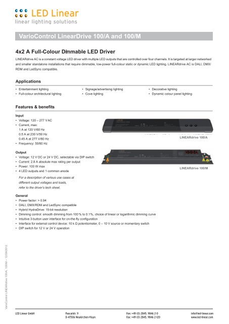
VarioControl <strong><strong>Linear</strong>Drive</strong> <strong>100</strong>/A <strong>and</strong> <strong>100</strong>/M<br />
4x2 A Full-Colour Dimmable <strong>LED</strong> Driver<br />
LINEARdrive AC is a constant voltage <strong>LED</strong> driver with multiple <strong>LED</strong> outputs that are controlled over four channels. It is targeted at larger networked<br />
<strong>and</strong> smaller st<strong>and</strong>alone installations that require dimmable, low-power full-colour static or dynamic <strong>LED</strong> lighting. LINEARdrive AC is DALI, DMX/<br />
RDM <strong>and</strong> LedSync compatible.<br />
Applications<br />
• Entertainment lighting<br />
• Full-colour architectural lighting<br />
Features & benefits<br />
Input<br />
• Voltage: 120 – 277 V AC<br />
• Current, max:<br />
1 A at 120 V/60 Hz<br />
0.5 A at 230 V/50 Hz<br />
0.45 A at 277 V/60 Hz<br />
• Frequency: 50/60 Hz<br />
• Signage/advertising lighting<br />
• Cove lighting<br />
Output<br />
• Voltage: 12 V DC or 24 V DC, selectable via DIP switch<br />
• Current: 2.8 A absolute max rating per output<br />
• Power: <strong>100</strong> W max<br />
• 4 <strong>LED</strong> outputs <strong>and</strong> 1 common anode<br />
For a description of various use cases at<br />
different output voltages <strong>and</strong> loads,<br />
refer to the driver’s tech sheet.<br />
General<br />
• Power factor: > 0.94<br />
• DALI, DMX/RDM <strong>and</strong> LedSync compatible<br />
• Hybrid HydraDrive: 15-bit resolution<br />
• Dimming control: smooth dimming from <strong>100</strong> % to 0.1%, choice of linear or logarithmic dimming curve<br />
• Intuitive 3-button user interface for on-the-fly configuration<br />
• Interface for external control device: 10 k Ω potentiometer, 0 – 10 V source or momentary switch<br />
• DIP switch for 12 V or 24 V operation<br />
• Decorative lighting<br />
• Dynamic colour panel lighting<br />
LINEARdrive <strong>100</strong>/A<br />
LINEARdrive <strong>100</strong>/M
VarioControl LINEARdrive <strong>100</strong>/A, <strong>100</strong>/M – 12/09/2012<br />
VarioControl <strong><strong>Linear</strong>Drive</strong> <strong>100</strong>/A <strong>and</strong> <strong>100</strong>/M<br />
Dimensions, weight, packaging<br />
LINEARdrive <strong>100</strong>/A<br />
• Weight: 705 g, 26 oz<br />
LINEARdrive <strong>100</strong>/M<br />
• Weight: 880 g, 31 oz<br />
Connections<br />
Connectors<br />
• Power: Line, Neutral <strong>and</strong> Ground<br />
• DALI: + <strong>and</strong> - (x2)<br />
• DMX in: +, - <strong>and</strong> shield<br />
• LedSync out: +, - <strong>and</strong> shield<br />
• Ext in: + <strong>and</strong> -<br />
Other information<br />
Certifications<br />
ø 5.0 mm/0.2”<br />
ø 5.0 mm/0.2”<br />
• IEC 61347-1, IEC 61347-2-13, IEC 62384 + A1, EN 55015 + A1,<br />
EN 55022 + A1, IEC 6<strong>100</strong>0-3-2, IEC 61547 + A1, IEC 62386-207<br />
• CE<br />
• ENEC by VDE<br />
• UL: Recognized Component for US <strong>and</strong> Canada (file no. E333135),<br />
according to UL1310 <strong>and</strong> UL8750. Class 2 output for US <strong>and</strong><br />
Canada.<br />
<strong>LED</strong> <strong>Linear</strong> GmbH<br />
<strong>LED</strong> <strong>Linear</strong> GmbH<br />
354 mm/13.94”<br />
388 mm/15.27”<br />
361 mm/14.21”<br />
370 mm/14.57”<br />
Connectors (cont’d)<br />
• <strong>LED</strong> outputs: 4 outputs with common +<br />
• <strong>LED</strong>code/NTC: + <strong>and</strong> -<br />
Wiring<br />
• Cross section: 0.5 – 1.5 mm 2 , AWG 20 – 16<br />
• Strip length: 9 mm/0.35 in.<br />
Environmental ratings<br />
• Ta range: -40°C...50°C/-40°F...122°F<br />
M<br />
• Tc max: 90°C/194°F (<strong>100</strong>/A) <strong>and</strong> 85°C/185°F (<strong>100</strong>/M)<br />
• For use in damp <strong>and</strong> dry locations<br />
Control compatibility<br />
• DALI control gear<br />
M<br />
42 mm<br />
1.65”<br />
41 mm<br />
1.61”<br />
30 mm/1.18”<br />
30 mm/1.18”<br />
• DMX512A <strong>and</strong> RDM explore & address (ANSI E1.20) control gear<br />
• St<strong>and</strong>ard passive 0 – 10 V switch controls
VarioControl LINEARdrive <strong>100</strong>/A, <strong>100</strong>/M – 12/09/2012<br />
VarioControl <strong><strong>Linear</strong>Drive</strong> <strong>100</strong>/A <strong>and</strong> <strong>100</strong>/M – Wiring diagram<br />
N<br />
120 – 277{ VAC<br />
L<br />
DALI{<br />
Pay attention when connecting the <strong>LED</strong> groups:<br />
polarity reversal results in no light output <strong>and</strong><br />
often damages the <strong>LED</strong>s<br />
WARNING: Risk of electrical shock. May result in serious injury or death. Disconnect power before servicing or installing.<br />
CAUTION: The device may only be connected <strong>and</strong> installed by a qualified electrician. All applicable regulations, legislation <strong>and</strong> building<br />
codes must be observed. Incorrect installation of the device can cause irreparable damage to the device <strong>and</strong> the connected <strong>LED</strong>s.<br />
120 – 277 V AC<br />
The driver accepts a universal mains voltage input of 120 – 277 V AC,<br />
50/60 Hz.<br />
DALI<br />
Use these connectors to connect the driver to a DALI network. Always<br />
combine a DA+ <strong>and</strong> DA- connector for either data input or data output.<br />
DMX in/LedSync out<br />
Use these connectors when the driver is used in a DMX network. For<br />
DMX in, connect the network cable’s DMX+, DMX- <strong>and</strong> DMX shielding<br />
wire (the orange/white, orange <strong>and</strong> brown wire in a CAT5 cable) to the<br />
DMX in+, DMX in- <strong>and</strong> DMX in shield connector respectively. For<br />
LedSync out, connect the network cable’s DMX+, DMX- <strong>and</strong> DMX<br />
shielding wire to the LedSync out+, LedSync out- <strong>and</strong> LedSync out<br />
shield connector respectively.<br />
<strong>LED</strong> groups<br />
Indicates the location of the connectors for your <strong>LED</strong> groups. R(ed)<br />
represents channel 1, G(reen) represents channel 2, B(lue) repre-<br />
sents channel 3 <strong>and</strong> W(hite) represents channel 4. One common an-<br />
ode provides the positive supply voltage for all four <strong>LED</strong> groups. The<br />
default group color allocation can be changed over the 3-button user<br />
interface.<br />
+<br />
-<br />
+<br />
-<br />
1<br />
2<br />
0.5 – 1.5 mm 2<br />
AWG 20 – 16<br />
LedSync out +<br />
LedSync out -<br />
LedSync out shield<br />
9 mm<br />
0.35 inch<br />
1<br />
2<br />
0.2 – 1.5 mm 2<br />
AWG 24 – 16<br />
9 mm<br />
0.35 inch<br />
Ext in -<br />
Ext in +<br />
<strong>LED</strong> wiring distance<br />
Maximum wiring distance at full load:<br />
AWG value 24 22 21 20 19 18 17 16<br />
Distance (m) 2 3 4 5 6 8 10 13<br />
Distance (ft) 6.6 9.8 13.1 16.4 19.7 26.2 32.8 42.7<br />
Ext in<br />
You have the possibility to connect an external control device (0 – 10 V<br />
control device, 10 k Ω potentiometer or show selection switch) to the<br />
driver’s Ext in+ <strong>and</strong> Ext in- connectors. Configure the driver for use<br />
with an external control device over the 3-button user interface.<br />
12 – 24 V DIP switch<br />
Set DIP switch 1 to ON when you’re connecting a 24 V <strong>LED</strong> strip; set<br />
DIP switch 1 to OFF when you’re connecting a 12 V <strong>LED</strong> strip. (DIP<br />
switch 2 is not used.)<br />
DMX in shield<br />
DMX in -<br />
DMX in +<br />
Common anode<br />
4 <strong>LED</strong> groups, 4 control channels<br />
R G B<br />
12 V/24 V DIP switch<br />
24 V 12 V<br />
Non functional<br />
Warning: setting DIP switch 1 to ON for use with 24 V <strong>LED</strong>s <strong>and</strong> sub-<br />
sequently connecting 12 V <strong>LED</strong>s can damage the <strong>LED</strong>s!<br />
R<br />
W<br />
R R R
VarioControl LINEARdrive <strong>100</strong>/A, <strong>100</strong>/M – 12/09/2012<br />
VarioControl <strong><strong>Linear</strong>Drive</strong> <strong>100</strong>/A <strong>and</strong> <strong>100</strong>/M – Wiring diagram<br />
Connecting an RGB <strong>LED</strong> strip<br />
Maximum current per output at 12 V: 2.77 A<br />
Maximum current per output at 24 V: 1.33 A<br />
Configuration of the <strong>LED</strong> groups:<br />
Press M <strong>and</strong> + simultaneously, in<br />
save by pressing M.<br />
Connecting an RGB strip <strong>and</strong> a white <strong>LED</strong> strip<br />
Maximum current per output at 12 V: 2 A<br />
Maximum current per output at 24 V: 1 A<br />
Configuration of the <strong>LED</strong> groups:<br />
Press M <strong>and</strong> + simultaneously, in the <strong>LED</strong> menu<br />
choose RGBW <strong>and</strong> save by pressing M.<br />
Connecting warm white <strong>and</strong> cool white <strong>LED</strong> strips<br />
Maximum current per output at 12 V: 2 A<br />
Maximum current per output at 24 V: 1 A<br />
Configuration of the <strong>LED</strong> groups:<br />
Press M <strong>and</strong> + simultaneously, in the <strong>LED</strong> menu<br />
choose 4 – 4 L <strong>and</strong> save by pressing M.<br />
Connecting four white or self-colored <strong>LED</strong> strips<br />
Maximum current per output at 12 V: 2 A<br />
Maximum current per output at 24 V: 1 A<br />
Configuration of the <strong>LED</strong> groups:<br />
Press M <strong>and</strong> + simultaneously, in the <strong>LED</strong> menu<br />
choose 1 – 4 L <strong>and</strong> save by pressing M.<br />
Compact<br />
connector<br />
e.g. Wago 222<br />
Compact<br />
connector<br />
e.g. Wago 222<br />
Compact<br />
connector<br />
e.g. Wago 222<br />
+<br />
R<br />
G<br />
B<br />
+<br />
R<br />
G<br />
B<br />
+<br />
-<br />
RGB <strong>LED</strong> strip<br />
RGB <strong>LED</strong> strip<br />
White <strong>LED</strong> strip<br />
Warm white <strong>LED</strong> strip<br />
+<br />
-<br />
Cool white <strong>LED</strong> strip<br />
+<br />
-<br />
Warm white <strong>LED</strong> strip<br />
+<br />
-<br />
Cool white <strong>LED</strong> strip<br />
+<br />
-<br />
+<br />
-<br />
+<br />
-<br />
+<br />
-<br />
+<br />
-<br />
White <strong>LED</strong> strip<br />
White <strong>LED</strong> strip<br />
White <strong>LED</strong> strip<br />
White <strong>LED</strong> strip
VarioControl LINEARdrive <strong>100</strong>/A, <strong>100</strong>/M – 12/09/2012<br />
VarioControl <strong><strong>Linear</strong>Drive</strong> <strong>100</strong>/A <strong>and</strong> <strong>100</strong>/M – Quick Start Guide<br />
Manual configuration<br />
1. Select mode of operation<br />
M<br />
display off<br />
2. Set <strong>LED</strong> groups<br />
(5 sec)<br />
Set mode<br />
MODE<br />
SET<br />
M<br />
COLR<br />
SHOW<br />
DMX<br />
DALI<br />
3. St<strong>and</strong>alone St<strong>and</strong>alone Networked<br />
operation or operation or operation<br />
- Colour*- - Show - - DMX or DALI -<br />
M<br />
Hue<br />
HUE<br />
M<br />
White<br />
WHIT<br />
M<br />
Intensity<br />
INT<br />
M<br />
display off<br />
M<br />
+<br />
<strong>LED</strong> groups<br />
<strong>LED</strong><br />
M<br />
External input<br />
EXT INP<br />
M<br />
Dimming curve<br />
DIM CURV<br />
M<br />
display off<br />
* The colour menu depends on the <strong>LED</strong><br />
group settings you have selected in step 2.<br />
/<br />
1-1L RGB<br />
2-2L RGBW<br />
3-3L RGBA<br />
4-4L RRGB<br />
2-4L RGGB<br />
1-4L CCWW<br />
CWWW<br />
+ -<br />
+<br />
OFF<br />
POTM<br />
10V<br />
SWIT<br />
LOG<br />
LIN<br />
/<br />
+ -<br />
/<br />
+ -<br />
/<br />
+ -<br />
M<br />
SHOW<br />
M<br />
M<br />
M<br />
display off<br />
00...20<br />
-99...99<br />
0...255<br />
/<br />
M<br />
DMX address<br />
DMX<br />
M<br />
Network resolution<br />
NETW<br />
M<br />
M<br />
ADDR<br />
RES<br />
DMX termination<br />
TERM<br />
M<br />
Network setup<br />
NETW SET<br />
Interpolation<br />
INTERPOL<br />
M<br />
display off<br />
1...512<br />
8 BT<br />
16 BT<br />
YES<br />
NO<br />
AUTO<br />
MANU<br />
OFF<br />
VID<br />
COLR<br />
WHIT<br />
GLOW<br />
/<br />
/<br />
0...1535<br />
Show<br />
Speed<br />
SPD<br />
Intensity<br />
INT<br />
+ -<br />
+ -<br />
/<br />
/<br />
+ -<br />
+ -<br />
/<br />
/<br />
0...255<br />
+ -<br />
/<br />
0...510<br />
+ -<br />
+ -<br />
/<br />
+ -<br />
+ -<br />
/<br />
+ -<br />
/<br />
+ -<br />
NO<br />
ADDR<br />
M<br />
No address Address set<br />
ADDR<br />
SET<br />
M M<br />
Nr. of ballasts<br />
X BAL<br />
M<br />
display off<br />
Other features<br />
Locking the configuration<br />
Visual test run<br />
M<br />
M<br />
+<br />
Lock driver<br />
LOCK<br />
M<br />
display off<br />
Reset to factory defaults<br />
M<br />
+ +<br />
Test<br />
TEST<br />
R 1 sec<br />
G 1 sec<br />
B 1 sec<br />
W 1 sec<br />
RGBW 1 sec<br />
R 1 sec<br />
G 1 sec<br />
B 1 sec<br />
W 1 sec<br />
RGBW 1 sec<br />
display off<br />
+ +<br />
Reset<br />
RE - SET<br />
PRES MENU<br />
Press menu<br />
M<br />
display off<br />
+<br />
(5 sec)<br />
NO<br />
SOFT<br />
HARD<br />
/<br />
+ -<br />
-<br />
+<br />
-<br />
+<br />
(5 sec)