www.futurepipe.com/usa
www.futurepipe.com/usa
www.futurepipe.com/usa

Create successful ePaper yourself
Turn your PDF publications into a flip-book with our unique Google optimized e-Paper software.
Page 26 of 51<br />
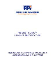
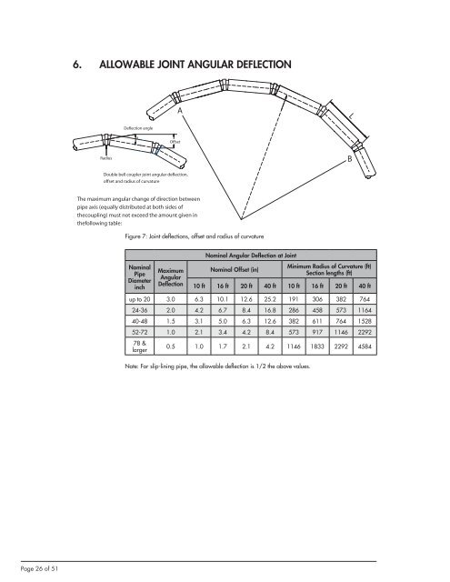
6. ALLOWABLE JOINT ANGULAR DEFLECTION<br />
Radius<br />
Deflection angle<br />
a<br />
Figure 7: Joint deflections, offset and radius of curvature<br />
Figure 7: Joint deflections, offset and radius of curvature<br />
Nominal<br />
Pipe<br />
Diameter<br />
inch<br />
Offset<br />
Double bell coupler joint angular deflection,<br />
offset and radius of curvature<br />
The maximum angular change of direction between<br />
The maximum angular change of direction between<br />
pipe axis (equally distributed at both sides of the<br />
pipe axis (equally distributed at both sides of<br />
coupling) must not exceed exeed the amount given in the<br />
thecoupling) must not exceed the amount given in<br />
following table:<br />
thefollowing table:<br />
A<br />
Maximum<br />
Angular<br />
Deflection<br />
Nominal Angular Deflection at Joint<br />
Nominal Offset (in)<br />
Minimum Radius of Curvature (ft)<br />
Section lengths (ft)<br />
10 ft 16 ft 20 ft 40 ft 10 ft 16 ft 20 ft 40 ft<br />
up to 20 3.0 6.3 10.1 12.6 25.2 191 306 382 764<br />
24-36 2.0 4.2 6.7 8.4 16.8 286 458 573 1164<br />
40-48 1.5 3.1 5.0 6.3 12.6 382 611 764 1528<br />
52-72 1.0 2.1 3.4 4.2 8.4 573 917 1146 2292<br />
78 &<br />
larger<br />
0.5 1.0 1.7 2.1 4.2 1146 1833 2292 4584<br />
Note: For slip-lining pipe, the allowable deflection is 1/2 the above values.<br />
L<br />
B