Installation Manual - Future Pipe Industries
Installation Manual - Future Pipe Industries
Installation Manual - Future Pipe Industries

Create successful ePaper yourself
Turn your PDF publications into a flip-book with our unique Google optimized e-Paper software.
Wavistrong ®<br />
<strong>Installation</strong> <strong>Manual</strong><br />
REP 320/REV 02/0401<br />
Date of issue:<br />
01-04-2001<br />
Replaces issue:<br />
01-04-1998<br />
Wavistrong <strong>Installation</strong> <strong>Manual</strong><br />
1
All information was correct at the time of going to press. However, we reserve the right to alter, amend and update<br />
any products, systems and services described in this brochure. We accept no responsibility for the interpretations of<br />
statements made.<br />
© Copyright by <strong>Future</strong> <strong>Pipe</strong> <strong>Industries</strong> B.V.<br />
No part of this work may be reproduced in any form, by print, photo print, microfilm or any other means without<br />
written permission from the publisher.<br />
Wavistrong <strong>Installation</strong> <strong>Manual</strong><br />
2
Table of Contents<br />
1. Introduction 5<br />
1.2. Systems 5<br />
1.3. Series identification 5<br />
2. Handling of R.T.R.P. material: Transport and storage 6<br />
2.1. Loading 6<br />
2.2. Unloading 7<br />
2.3. Storage of material 8<br />
3. Jointing and preparation methods of Wavistrong 10<br />
3.1. Cutting 10<br />
4. Adhesive bonded joints 11<br />
4.1. Tools for adhesive bonded joints 12<br />
4.2. Machining 12<br />
4.3. Bonding of the joint 12<br />
4.4. <strong>Installation</strong> time for adhesive bonded joints 14<br />
4.5. Allowable bending radius 14<br />
5. Integral Rubber seal joint (RSJ) and Rubber Seal Lock Joint (RSLJ) 15<br />
5.1. Tools for rubber seal joints 15<br />
5.2. Rubber Seal Joint 15<br />
5.2.1. Rubber Seal Joint (RSJ) with pipe stop 15<br />
5.2.2. Rubber Seal Joint (RSJ) without pipe stop 16<br />
5.2.3. Rubber Seal Lock Joint (RSL J) with pipe stop 17<br />
5.2.4. Rubber Seal Lock Joint (RSL J) without pipe stop 18<br />
5.3. Dimensions of rubber ring and locking strip 19<br />
5.4. <strong>Installation</strong> time for rubber seal joints 21<br />
5.5. Disassembly of rubber seal joints 23<br />
6. Flanged joints 25<br />
6.1. Tools for flanged joints 25<br />
6.2. Flanged joints 25<br />
6.3. Gaskets and maximum torques 27<br />
6.3.1. Torques for assembly of rubber gaskets with steel insert 27<br />
6.3.2. Torques for assembly of rubber gaskets with supporting ring 28<br />
6.4. Assembly and disassembly of flanged equipment 28<br />
6.5. Determination of the bolt lengths 29<br />
7. Butt and wrap joints 30<br />
7.1. Tools for butt and wrap joints 30<br />
7.2. Cutting and shaving 30<br />
7.3. Mixing 30<br />
7.4. Fit layer 30<br />
7.5. Laminating 30<br />
7.6. Curing 31<br />
8. Mechanical couplers 32<br />
8.1. Tools for mechanical couplers 32<br />
8.2. Mechanical couplers 32<br />
Wavistrong <strong>Installation</strong> <strong>Manual</strong><br />
3
9. <strong>Installation</strong> of underground systems 33<br />
9.1. The trench construction 34<br />
9.2. <strong>Pipe</strong> assembly 36<br />
9.3. Backfilling 38<br />
9.3.1. Other methods of backfilling 39<br />
9.3.2. <strong>Pipe</strong> systems to be cast in concrete 39<br />
9.4. Subsidence 40<br />
9.5. Relief plates 41<br />
9.6. <strong>Installation</strong> of underwater mains 42<br />
9.7. Hydrant connections 44<br />
10. <strong>Installation</strong> of above ground pipe systems 45<br />
10.1. Supports 45<br />
10.1.1. Protection of the pipe 45<br />
10.1.2. Extra supports 45<br />
10.2. Fixed supports 44<br />
10.3. <strong>Pipe</strong> clips 46<br />
10.4. Valves 48<br />
10.5. Bellows 50<br />
10.6. Connection to other materials 52<br />
10.7. Algae growth 53<br />
10.8. U.V. resistance 54<br />
10.9. Electrically conductive pipe 55<br />
10.10. Wall penetration and connection to or through walls 56<br />
11. Field test procedure 59<br />
11.1. Filling, saturation and testing 59<br />
11.2. Causes of pressure drop 60<br />
12. Safety precautions 60<br />
Wavistrong <strong>Installation</strong> <strong>Manual</strong><br />
4
1. Introduction<br />
This manual is written as a guide for supervisors and field engineers and explains the possibilities of Wavistrong<br />
systems. In addition this manual provides guidance on how to avoid and solve problems during installation.<br />
Reinforced thermosetting resin pipe (R.T.R.P.) systems offer, by their specific nature, many applications and<br />
advantages compared with other materials. In order to utilize all these properties it is essential, for those<br />
who use Wavistrong material, carefully to observe these guidelines.Please note that these instructions are for<br />
guidance only. Specifications written for a particular project will have priority.<br />
Although the procedures written in this manual are as complete as possible, it is not possible to describe all the<br />
different circumstances you may meet. For this reason our experienced supervisors may vary the described procedures<br />
in order to achieve an optimum solution, using the latest installation techniques and processing methods.<br />
1.2. Systems<br />
Wavistrong pipeline systems are produced from glass fibres, impregnated with an aromatic or cyclo-aliphatic amine<br />
hardened epoxy resin.<br />
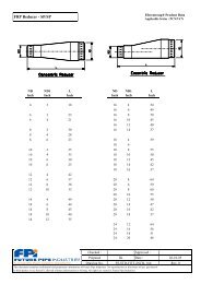
This thermo hardened resin system offers superior<br />
Top layer<br />
corrosion resistance together with excellent mechanical,<br />
Reinforced wall<br />
physical and thermal properties.<br />
Resin liner<br />
The glass fibre reinforced epoxy pipeline is resistant to<br />
the corrosive effect of mixtures with a low concentration<br />
of acids, neutral or nearly neutral salts, solvents and<br />
caustic substances, under both internal and external<br />
W<br />
pressure.<br />
The cross wound continuous glass fibres of the reinforced<br />
(structural) wall of the pipes and the supports are protected<br />
on the inside by the resin reinforced liner and on the outside<br />
by the resin top coat.<br />
Fig. 1.2.a.<br />
1.3. Series identification<br />
The series identification comprises two parts, namely:<br />
Type identification<br />
The type of product is identified by three alphabetic letters<br />
1. Type matrix E stands for epoxy resin,<br />
C stands for electrically conducting epoxy resin<br />
2. Type of application: S stands for standard,<br />
W for drinking water<br />
3. Type of joint: T stands for tensile,<br />
N for non-tensile<br />
Pressure class<br />
This number gives the maximum permissible internal pressure (bar) which the product can withstand during a working<br />
life of 50 years, with a service (design) factor (Sf) of 0.5, which means a safety factor of 2.<br />
For example: Series EST 20 means: Epoxy resin<br />
Standard application:<br />
Tensile resistant joints<br />
Nominal pressure 20 bar.<br />
Wavistrong <strong>Installation</strong> <strong>Manual</strong><br />
5
2. Handling of R.T.R.P. material: Transport and storage<br />
2.1. Loading<br />
<strong>Pipe</strong>s, fittings and prefabricated parts (spools) have to be transported by suitable trucks. These trucks must have flat<br />
floors. Check for and remove any projections or nails etc. before each load. Materials must be secured for example<br />
by using wedges and wooden supports. These supports must have a minimum width of 10 cm, avoiding sharp edges.<br />
Usually the materials are tied in place, using pliable nylon or canvas slings. Chains or steel cables may not be used<br />
under any circumstances.<br />
Fig. 2.1.a.<br />
The support distances must not exceed 2.5 m. The width of the supports must be a minimum of 10 cm. When pipes<br />
are inserted (one inside the other), the support distance shall not exceed 2 m. Flanges must be secured against sliding.<br />
Flanges may only be loaded on their sealing face if they are sufficiently protected against damage.<br />
Fig. 2.1.b.<br />
The best way for fittings to be transported is in crates or onto pallets. Direct contact between products during transport<br />
must be avoided.<br />
<strong>Pipe</strong> ends and machined parts must be protected, for example, by means of straw mats covered by polyethylene sheet<br />
or polyethylene netting. <strong>Pipe</strong>s and spools should be lifted by using nylon or canvas hoisting belts with a minimum<br />
width of 10 cm and must be lifted at two points, using the largest diameter of the prefabricated part (spool), in such<br />
a way that the weight is well-balanced.<br />
Any part of the truck has to be protected by wood or rubber wherever in contact with the products. We recommend<br />
the use of trucks which can be loaded from the sides. If pipes are handled by a forklift truck, the forks must be covered<br />
with rubber or plastic.<br />
Wavistrong <strong>Installation</strong> <strong>Manual</strong><br />
6
2.2. Unloading<br />
The unloading of material is the responsibility of the client, unless agreed otherwise.<br />
Because of the relative lightness of glassfibre reinforced plastics (approximately a quarter compared to steel) handlers<br />
may be tempted to handle it roughly, or unload it by letting it drop of its own accord. This may cause serious damage<br />
to the material and therefore Wavistrong material should be handled with care.<br />
Fig. 2.2.a.<br />
Do not use chains, steel cables or clamps during lifting. Nylon or canvas hoisting belts with a minimum width of 10 cm<br />
must be used. Standard pipe lengths must be picked up at two supporting points. Ensure that hoisting belts are always<br />
put round the widest part. We strongly recommend that the pipes are unloaded one at a time when hoisting belts<br />
are used. Each consignment is carefully loaded and must be inspected on site in order to ensure that no damage has<br />
occurred during transportation. This will avoid disputes with regards to responsibilities.<br />
Wavistrong <strong>Installation</strong> <strong>Manual</strong><br />
7
2.3. Storage of material<br />
In order to avoid damage to the stacked pipes, the following rules are important:<br />
A Do not lay the pipes directly on the ground, onto rails or concrete floors. Provide a flat surface.<br />
Fig. 2.3.a.<br />
B Ensure suitable supports are used for example wooden beams, measuring 10 x 5 cm. To avoid damage to<br />
machined pipe ends, stacking should be undertaken with care. The machined ends must be protected for example<br />
by polyethylene covered straw mats or polyethylene netting. The socket and spigot ends must not touch each other.<br />
C The pipes can be stacked economically by alternating the spigot and the socket, as illustrated below. In order to<br />
avoid bending of the pipes, the beams should be laid directly above each other in a vertical line. Supports should<br />
be spaced at a max. of 3 metre intervals and about 1 metre from each end. The width of the supports should be<br />
at least 10 cm. The maximum allowable stack height is 1.5 metres. However, for diameters of 800 mm and above,<br />
a maximum of 2 pipes may be stacked one on top of the other.<br />
Fig. 2.3.b.<br />
~1m.<br />
max. 3m.<br />
D If the product is stacked too high for long storage periods (6-12 months) and subjected to high temperatures,<br />
the supports may cause flattening. It is recommended that the product ( in particular machined parts) is stored<br />
under tarpaulins or (white) polyethylene sheeting.<br />
E <strong>Pipe</strong> stacks should have side supports or blocks to prevent rolling or slipping of the stack during stormy weather.<br />
F Store rubber o-rings, gaskets, plastic locking strips, adhesive kits, resins, hardeners, woven roving and lubricants<br />
in its original pack, below 35(C. Keep dry, away from frost, direct sunlight and ozone.<br />
Observe the shelf life of the adhesives and resins. It is preferable to order these as required.<br />
Wavistrong <strong>Installation</strong> <strong>Manual</strong><br />
8<br />
max. 3m. ~1m.
G Unprotected flange-faces should never be placed directly on the ground or on concrete floors.<br />
H If any damage during transportation or installation is noticed such as scratches, cracks or pits,<br />
<strong>Future</strong> <strong>Pipe</strong> <strong>Industries</strong> should be contacted for any repair or replacement. Never use any damaged material!<br />
I Crystallisation can take place at temperatures lower then 20°C The resin is then milky in appearance and<br />
is congealed. The resin can be made liquid again by re-heating it. A temperature of between 40°-50°C<br />
is required for this purpose. Before mixing the resin and hardener for use, the resin must be stirred thoroughly.<br />
Wavistrong <strong>Installation</strong> <strong>Manual</strong><br />
9
3. Jointing and preparation methods of Wavistrong<br />
There are several methods available for the installation and adjusting of pipe systems in the field. The following jointing<br />
methods are described in chapters 4 to 8.<br />
A Adhesive bonded joint<br />
B Rubber seal joint<br />
C Flanged joint<br />
D Lamination joint<br />
E Mechanical coupler<br />
In case it is necessary to shorten the pipe length at a certain point in the line, re-jointing can be performed by adhesive<br />
bonding or by laminating. The adhesive bonded joint is available up to and including a diameter of 400 mm.<br />
Mechanical couplers such as Straub, Viking Johnson, Taylor Kerr and Dresser can be used. However, these mechanical<br />
couplers are non-restrained and cannot resist any axial loadings. Additional restraint will be required.<br />
3.1 Cutting<br />
The pipe section to be cut should be marked using a marker pen and a pipe fitter's wrap-a-round guide.<br />
Ensure that the cut end is completely square as the reliability of the joint depends on it. The cutting of glassfibre<br />
reinforced epoxy pipes can be done by means of a hacksaw for diameters up to 100 mm. For diameters above<br />
100 mm an (abrasive) cutting disc (diagrit or carborundum) can be used.<br />
Do not cut close to the socket end of a rubber seal joint and/or adhesive bonded joint. The cutting distance away from<br />
the conical part of the bell end must be equal to, or longer than the length Lv for laminated joints (see Wavistrong<br />
Field Laminate Instructions) and SA + 50 mm for adhesive bonded joints (see Wavistrong Adhesive Instructions).<br />
Fig. 3.1.a.<br />
Fig. 3.1.b.<br />
LV<br />
pipe with<br />
integral socket<br />
pipe with<br />
integral socket<br />
SA+50<br />
adhesive finishing<br />
layer<br />
Wavistrong <strong>Installation</strong> <strong>Manual</strong><br />
10<br />
rubber ring<br />
securing strip<br />
stop<br />
insert hole for securing strip<br />
pipe with spigot<br />
end rubber ring<br />
pipe with<br />
spigot end
4. Adhesive bonded joints<br />
Before adhesive bonding, all safety precautions will need to be checked. Ensure that all necessary tools and materials<br />
are available (see chapter 12. and 4.1.).<br />
Adhesive bonded joints can only be made by fully trained and certified personnel.<br />
4.1 Tools for adhesive bonded joints<br />
For assembly of adhesive bonded joints the following is needed:<br />
A measuring tape + marker pen + pipe fitter's wrap-a-round + measuring gauge<br />
B pipe clamp + bench + rubber strip (for use underneath the chain clamp)<br />
C angle grinder with diagrit or carborundum cutting disc (grain 24) flapper sander and a sanding bobbin,<br />
a handsaw with a 24 teeth/inch blade, jig saw with a 14 teeth/inch blade<br />
D shaver<br />
E cleaning rag<br />
F adhesive, spatula (=rubber scraper plate), emery cloth<br />
G heating blanket, hot air gun (paint stripper gun), digital temperature gauge, variable energy control (rheostat),<br />
insulation blanket<br />
H generator<br />
I cleaning fluid/gloves/dust mask/safety glasses.<br />
J shelter (depending on the weather conditions)<br />
For adhesive bonding: see instructions included with the cement kit.<br />
For machining: see shaver instructions supplied with the shaver.<br />
Note: <strong>Future</strong> <strong>Pipe</strong> <strong>Industries</strong> supplies two types of adhesive:<br />
- Easyfit Adhesive is suitable for standard EST and for EWT drinking water systems,<br />
both suitable for a medium temperature up to 110°C.<br />
- Easyfit Conductive Adhesive is suitable for systems with electrically conducting properties (CST)<br />
for medium temperatures up to 110ºC.<br />
4.2 Machining<br />
After the pipe has been cut to the exact length, the end will have be machined to the right diameter to ensure a proper<br />
joint. The surface has to be cleaned with a clean cloth.<br />
If the surface has been in contact with oil or grease, it should be cleaned with a clean cloth soaked in pure acetone,<br />
M.E.K. (methyl ethyl ketone) or M.I.B.K. (methyl isobutyl keton) (free of water). Do not use paint thinners, petrol or<br />
alcohol for cleaning. After drying, machining can start. There are 3 shavers available: one for diameters up to 50 mm,<br />
one for diameters from 80 mm to 250 mm and one for diameters from 200 mm to 400 mm.<br />
Fig. 4.1.a.<br />
Wavistrong <strong>Installation</strong> <strong>Manual</strong><br />
11
Instructions for the shaver adjustment and machining are provided with the tools.<br />
If a factory made spigot end is not available for adjusting the tool, then the tool can be adjusted so that the machined<br />
spigot end jams about 10 mm away from the stop collar in the prepared socket end. This ensures a tight fit. After<br />
the adhesive is applied a good bond is guaranteed. Any irregularity in thickness can be determined by measuring<br />
the spigot end in several places. On the machined spigot end the max. wall thickness difference allowed is 0.2% of<br />
the diameter of the pipe, with a minimum value of 0.3 mm. The spigot dimensions have to be in accordance with<br />
the values shown in the bonding instructions packed with the adhesive. Jointing by means of bonding with other RTRP<br />
systems from different manufacturers, where the outside diameter is larger than the Wavistrong system, is not allowed.<br />
In such cases the joint must be made by laminating.<br />
4.3. Bonding of the joint<br />
Fig. 4.3.a.<br />
temperature<br />
time<br />
heating<br />
The bonding instructions are packed with every adhesive kit.<br />
hardening cooling<br />
- The approximate number of joints which can be made with a standard package is as follows:<br />
Table 4.a. Number of joints using standard packagings<br />
PN Internal Diameter (mm)<br />
(bar) 25 40 50 80 100 150 200 250 300 350 400<br />
8-16 2 2 1.5 0.75 0.33 0.25<br />
20-32 20 15 10 6 4 2 1.5 1 0.75 0.33 0.25<br />
Wastage of adhesive can be reduced by good planning and the best use of the adhesive kits. Too much adhesive<br />
applied to the socket will reduce the diameter and result in restricted flow. Remove excess adhesive with the aid<br />
of the spatula and finish the seam properly and smoothly. This can also be done inside the pipe, for example,<br />
by pulling a plug through the pipe. This will prevents problems using foam pigs later.<br />
Wavistrong <strong>Installation</strong> <strong>Manual</strong><br />
12
The temperature of the heating blanket should be at least 90°C for applications of medium below 65°C and<br />
125°C for medium temperatures between 65°C and 90°C for the Easy fit adhesive.<br />
For detailed instructions we refer to the Wavistrong Easy fit Adhesive Instructions, enclosed in the Wavistrong<br />
Adhesive set.<br />
Curing time for Easy fit adhesive is one hour (see fig. 4.3.a. page 12) and one hour warming up time.<br />
Curing time starts after the surface of the pipe has reached the required temperature underneath the heating blanket.<br />
During curing the joint should be insulated for example by using an insulation blanket and seal off the pipe ends to<br />
prevent draughts through the pipe.<br />
Because of their configuration, flanged joints and laterals are difficult to cure from the outside by using a heating<br />
blanket. They can be cured with the following alternative procedure:<br />
A Roll up the heating blanket and place it on the inside of the pipe at the machined end. Fill the space inside<br />
the blanket with heat resistant material to ensure that the blanket is pressed against the pipe wall.<br />
The electrical cables must not be inside.<br />
B Heat the joint on the inside with a hot air gun / paint stripper or infra red device. Control the temperature with<br />
a digital temperature gauge. For laterals, the branch and the nearest joint must be cured first. The remaining parts<br />
can be cured with a heating blanket.<br />
Do not move the joint during setting of the adhesive! This can result in failure of the joint.<br />
After the cured joint has cooled down it may be loaded.<br />
Note In many cases the number of site joints can be reduced by prefabrication (spoolbuilding) in the factory.<br />
Wavistrong <strong>Installation</strong> <strong>Manual</strong><br />
13
4.4. <strong>Installation</strong> times of adhesive bonded joints<br />
Approximate times needed to make an adhesive bonded joint are shown in table 4.b. These estimated times are<br />
based on uninterrupted work, enough space and an open trench for underground applications the availability of<br />
all necessary materials, etc by a two persons installation team.<br />
Table 4.b. <strong>Installation</strong> times<br />
ID Time for Time for<br />
(mm) pre-processing (min) adhesion (min)<br />
25 10 10<br />
40 10 10<br />
50 10 15<br />
80 12 20<br />
100 12 25<br />
150 15 30<br />
200 15 35<br />
250 16 40<br />
300 18 45<br />
350 20 50<br />
400 25 60<br />
4.5. Allowable bending radius<br />
When installing the fully cured adhesive bonded joint system, it is possible to utilize the pipe's flexibility.<br />
The permitted bending radii are shown in the Wavistrong Engineering Guide. Bending of the adhesive bonded<br />
joint itself must be kept to a mimimum.<br />
Adhesive bonded joints must also be laminated when used in expansion loops, unless bending remains within<br />
certain limits. If in doubt <strong>Future</strong> <strong>Pipe</strong> <strong>Industries</strong> should be contacted.<br />
Wavistrong <strong>Installation</strong> <strong>Manual</strong><br />
14
5. Integral Rubber seal joint (RSJ) and Rubber Seal Lock Joint (RSLJ)<br />
Before assembling the Rubber Seal Joints, all safety precautions will need to be checked. Ensure that all necessary<br />
tools and materials are available. See chapter 12 and 5.1.<br />
5.1. Tools for rubber seal joints.<br />
Rubber Seal Joints<br />
For assembly of rubber seal joints the following is needed:<br />
A lubricant for O-ring and locking strip<br />
B a rod or stick<br />
C 2 pipe clamps<br />
D chain tackles (2): up to ID 500 mm pulling force 750 kg.<br />
ID > 500 mm pulling force 1500 kg.<br />
E plastic or wooden mallet to drive the locking strip into the rubber seal lock joint<br />
F non fluffy cleaning-rags<br />
5.2. Rubber Seal Joint<br />
The following actions must be taken in order to install the rubber seal joint.<br />
Fig. 5.2.a.<br />
pipe with<br />
integral socket end<br />
C<br />
free play<br />
5.2.1. Rubber Seal Joint (RSJ) with pipe stop<br />
- Clean the spigot and socket end thoroughly with a clean cloth before jointing.<br />
Do not use material like dusters in order to avoid fibres from sticking to the surface of the seal.<br />
- Check both pipe ends for damage.<br />
- Mark the depth of entry on the spigot end.<br />
- The measurement of the mark on the spigot end is as follows:<br />
depth of the socket end (dimension A) minus end play (dimension C) (see fig.5.2.a. and table 5.c., page 20).<br />
- Position the rubber ring into the groove of the spigot end.<br />
- Use a round tool like a screwdriver underneath the rubber ring and work it around<br />
a few times in order to distribute the tension (see fig. 5.2.d., page 17).<br />
A<br />
rubber ring<br />
Wavistrong <strong>Installation</strong> <strong>Manual</strong><br />
15<br />
pipe with spigot end<br />
mark
5.2.2 Rubber Seal Joint (RSJ) without pipe stop<br />
To assemble a rubber ring joint use this manual. For marking the depth of entry on the spigot end use the instruction<br />
below. Mark the depth of entry on the spigot end. The measurement of the mark on the spigot end is in table 5.a.<br />
Fig. 5.2.b.<br />
Table 5.a.<br />
L 2<br />
L mark<br />
pipe with<br />
integral socket end<br />
mark<br />
free play<br />
rubber ring<br />
Fig. 5.2.c.<br />
pipe with spigot end<br />
PN Angular<br />
ID ≤16 bar 20 bar ≥ 25 bar deflection<br />
(mm) Lmark L2 Lmark L2 Lmark L2 RSJ<br />
(mm) (mm) (mm) (mm) (mm) (mm)<br />
80 93 62 3°<br />
100 93 62 3°<br />
150 119 78 3°<br />
200 126 86 157 109 3°<br />
250 176 118 220 154 3°<br />
300 181 123 235 164 3°<br />
350 184 127 229 160 229 160 3°<br />
400 197 132 255 178 255 178 3°<br />
450 204 137 266 186 266 186 3°<br />
500 255 164 348 241 348 241 3°<br />
600 268 174 370 256 370 256 2°<br />
700 375 252 2°<br />
750 385 260 2°<br />
800 393 265 2°<br />
900 379 255 2°<br />
1000 394 265 2°<br />
1200 418 281 1°<br />
1400 418 278 1°<br />
Wavistrong <strong>Installation</strong> <strong>Manual</strong><br />
16<br />
mark
Fig. 5.2.d.<br />
- Apply <strong>Future</strong> <strong>Pipe</strong> <strong>Industries</strong> lubricant to the rubber ring and the entire inner surface of the socket end.<br />
- Avoid any lubricant under the rubber ring in order to prevent it from slipping out of the groove.<br />
Do not try to assembly the joint without the use of any lubricant. The standard lubricant can cause filters<br />
to block. <strong>Future</strong> <strong>Pipe</strong> <strong>Industries</strong> can supply lubricants which are soluble in water. Soft soap can be used<br />
as an alternative for the lubricant.<br />
- Fit the rubber lined clamps on both sides of the joint (fig. 5.2.e.).<br />
Fig. 5.2.e.<br />
- Ensure that the spigot end is positioned right in front of the socket end and that both sections are fully aligned.<br />
- Attach the chain tackles to the clamps on both sides of the parts to be connected and ease the spigot slowly<br />
and gradually into the socket until the mark is in line with the front of the socket end.<br />
- If in doubt, check with a thin feeler gauge around the circumference, to confirm that the rubber ring is in the<br />
right position in the groove.<br />
Wavistrong <strong>Installation</strong> <strong>Manual</strong><br />
17
Fig. 5.2.f.<br />
Note: The above mentioned clamps are available from <strong>Future</strong> <strong>Pipe</strong> <strong>Industries</strong>, but can also be made by the client<br />
according to <strong>Future</strong> <strong>Pipe</strong> <strong>Industries</strong>' drawings.<br />
Diameters up to 300 mm can be installed without the use of tackles. The force necessary to make the joint can<br />
be done by using a wooden beam as a lever at the end of the pipe.<br />
Do not try to join two pipes at an angle, since it is probable that the rubber ring may slip out of the groove.<br />
However, if necessary, only after assembly of the joint a permitted angle may be used (see table 5.c., page 20).<br />
Do not use the maximum permitted angle where you anticipate soil settlement.<br />
5.2.3. Rubber Seal Lock Joint (RSLJ) with pipe stop<br />
- Position the hole so the locking strip can be inserted easily.<br />
- Follow the assembly instructions for the rubber seal joints (RSJ).<br />
- Attach the chain tackles to the clamps on both sides of the pipe and ease the spigot end slowly and<br />
gradually into the socket end until the rear stop of the spigot end is past the hole of the locking strip.<br />
- Apply some lubricant on the first section of the locking strip.<br />
- Insert the locking strip in such a way that the bevelled end rests against the inside of the socket.<br />
Fig. 5.2.g.<br />
pipe with<br />
integral socket end<br />
c end play<br />
stop collar<br />
Wavistrong <strong>Installation</strong> <strong>Manual</strong><br />
18<br />
rubber ring<br />
locking strip<br />
insert hole for locking strip<br />
pipe with spigot end
5.2.4. Rubber Seal Lock Joint (RSLJ) without pipe stop<br />
To assemble a rubber ring joint use this manual. For marking the depth<br />
of entry on the spigot end use the instruction below.<br />
Fig. 5.2.h.<br />
pipe with<br />
integral socket end<br />
rubber ring<br />
locking strip<br />
Mark the depth of entry on the spigot end. The measurement of the mark on the spigot end is in table 5.b.<br />
Table 5.b.<br />
L 2<br />
L mark<br />
mark<br />
stop<br />
collar<br />
Wavistrong <strong>Installation</strong> <strong>Manual</strong><br />
19<br />
insert hole<br />
for locking strip<br />
Fig. 5.2.i.<br />
pipe with spigot end<br />
PN Angular<br />
ID ≤16 bar 20 bar ≥ 25 bar deflection<br />
(mm) Lmark L2 Lmark L2 Lmark L2<br />
RSLJ<br />
(mm) (mm) (mm) (mm) (mm) (mm)<br />
80 96 65 1°30<br />
100 96 65 1°30<br />
150 125 84 125 84 1°30<br />
200 134 94 134 94 165 117 1°30<br />
250 185 127 185 127 229 163 1°30<br />
300 191 133 191 133 245 174 1°30<br />
350 195 138 240 171 240 171 1°30<br />
400 210 145 268 191 268 191 1°30<br />
450 218 151 280 200 280 200 1°30<br />
500 271 180 364 257 364 257 1°30<br />
600 287 193 389 275 389 275 1°30<br />
700 391 268 1°<br />
750 402 277 1°<br />
800 411 283 1°<br />
900 400 276 1°<br />
1000 417 288 1°<br />
1200 445 308 1°<br />
1400 450 310 1°<br />
mark
Fig. 5.2.j.<br />
locking strip<br />
insert hole for locking<br />
spigot end<br />
socket end<br />
Tabel 5.c. Admissible angular deflection<br />
- Using a plastic hammer or a piece of wood, tap the<br />
locking strip home until it rests against the first part<br />
of the strip.<br />
- The end of the locking strip sticks out by approx.<br />
100 mm. This allows disassembly of the newly<br />
assembled joint.<br />
- Ensure that the stop of both the socket end and the<br />
spigot end are in contact with the locking strip and<br />
that the fully extended system is kept in this position.<br />
Note: At low temperatures a plastic locking strip may<br />
become less flexible. In that case it is advisable to warm<br />
the locking strip up to about 20(C.<br />
ID Play C Angular deflection<br />
(mm) (mm) RSLJ RSJ<br />
80 2.5 1˚30 3˚<br />
100 3.0 1˚30 3˚<br />
150 6.0 1˚30 3˚<br />
200 8.0 1˚30 3˚<br />
250 9.0 1˚30 3˚<br />
300 10.0 1˚30 3˚<br />
350 11.0 1˚30 3˚<br />
400 13.0 1˚30 3˚<br />
450 14.0 1˚30 3˚<br />
500 16.0 1˚30 3˚<br />
600 19.0 1˚30 2˚<br />
700 16.0 1˚ 2˚<br />
750 17.0 1˚ 2˚<br />
800 19.0 1˚ 2˚<br />
900 21.0 1˚ 2˚<br />
1000 23.0 1˚ 2˚<br />
1200 27.0 1˚ 1˚<br />
For RSJ systems an additional 'end play' of 30 mm is allowed for diameters up to 300 mm and 50 mm for diameters<br />
350 mm up to 1200 mm. This 'end play' allows for contraction as a result of pressure, temperature changes and soil<br />
settlements and therefore should not be used in the installation.<br />
Wavistrong <strong>Installation</strong> <strong>Manual</strong><br />
20
5.3. Dimensions of the rubber ring and the locking strip<br />
The commonly used rubber ring is made of NBR (Nitril Butadiene Rubber). Other types of rubber can be supplied<br />
depending on the medium and/or the temperature.<br />
The different types of rubber can be recognized by the following codes:<br />
S - styrene butadiene rubber SBR colour code red spot<br />
N - nitrile butadiene rubber NBR colour code yellow spot<br />
E - ethene propene terpolymer EPDM colour code blue spot<br />
F - fluor elastomer FKM<br />
H - hydrogenated nitrile butadiene rubber H-NBR<br />
Fig. 5.3.a.<br />
The dimensions d and D are shown on the O-ring as well as the year and month of production<br />
Table 5.d. O-rings dimensions<br />
d<br />
ID (mm) d (mm) D (mm)<br />
80 7 80<br />
100 7 109<br />
150 10 156<br />
200 10 207<br />
250 14 260<br />
300 14 311<br />
350 14 360<br />
400 17 409<br />
450 17 460<br />
500 22 508<br />
600 22 610<br />
700 26 690<br />
750 26 740<br />
800 26 790<br />
900 26 880<br />
1000 26 980<br />
1200 30 1120<br />
Wavistrong <strong>Installation</strong> <strong>Manual</strong><br />
21<br />
D
Fig. 5.3.b.<br />
B<br />
H<br />
Tabel 5.e. Locking strip dimensions<br />
PN (bar)<br />
ID (mm) min. max. H (mm) B (mm) length (mm) Pieces<br />
80 32 32 8 12 400 1<br />
100 25 32 8 12 400 1<br />
150 20 32 10 14 750 1<br />
200 16 20 10 14 750 1<br />
200 25 32 10 18 800 1<br />
250 12,5 20 16 20 1260 1<br />
250 25 32 16 30 1350 1<br />
300 12,5 20 16 20 1260 1<br />
300 25 32 16 30 1350 1<br />
350 8 16 16 20 1260 1<br />
350 20 25 16 30 1350 1<br />
400 8 16 16 20 1600 1<br />
400 20 25 16 30 1700 1<br />
450 8 16 16 20 1600 1<br />
450 20 25 16 30 1700 1<br />
500 8 16 20 24 2150 1<br />
500 20 25 23 40 2250 1<br />
600 8 16 20 24 2150 1<br />
600 20 25 23 40 2250 1<br />
700 8 16 23 40 2885 1<br />
750 8 16 23 40 2885 1<br />
800 8 16 23 40 2885 1<br />
900 8 12.5 23 40 1765 2<br />
1000 8 12.5 23 40 1765 2<br />
1200 8 34 38 2150 2<br />
Wavistrong <strong>Installation</strong> <strong>Manual</strong><br />
22
5.4. <strong>Installation</strong> time for the rubber ring joints<br />
Estimated installation times for the rubber ring joints on site are shown in table 5.f. and 5.g.<br />
These estimated times are based on<br />
- uninterrupted work<br />
- enough space and an open trench for underground applications, etc.<br />
- an installation crew of 3 persons (two in the trench, one outside)<br />
- excluding the handling of the pipe<br />
Table 5.f. <strong>Installation</strong> time<br />
ID (mm) Time (min.)<br />
80 5<br />
100 5<br />
150 5<br />
200 10<br />
250 15<br />
For diam. > 250 mm it has been taken into account that the pipe will be moved using the excavator.<br />
Table 5.g. <strong>Installation</strong> time<br />
Time for clamping<br />
ID (mm) and assembly of<br />
the joint (min.)<br />
300 15<br />
350 15<br />
400 15<br />
450 20<br />
500 20<br />
600 20<br />
700 20<br />
750 25<br />
800 25<br />
900 25<br />
1000 30<br />
1200 30<br />
Wavistrong <strong>Installation</strong> <strong>Manual</strong><br />
23
5.5. Disassembly of rubber seal joints<br />
In principal it is possible to take rubber seal joints apart within a short period after installation. In practice the joint<br />
will be cut out due to the lack of space to pull the spigot out of the socket, unless it is the last installed joint.<br />
The dismantling procedure for a rubber seal lock joint is as follows:<br />
- Push the pipe back into position to free up the locking strip if possible.<br />
- Grip the locking strip with a pair of pliers or a plate clamp.<br />
- Tap the pliers or use a crane to pull the plate clamp to remove the locking strip. (If the locking strip jams,<br />
turn the pipe a little while pulling the strip).<br />
- Pull the spigot end out of the socket until the rubber ring is positioned at the insertion hole of the locking strip.<br />
- Pull the rubber ring through this hole, cut the rubber ring and remove the ring completely through the hole.<br />
- Now the joint can be released completely.<br />
Fig. 5.5.a.<br />
Wavistrong <strong>Installation</strong> <strong>Manual</strong><br />
24
6. Flanged joints<br />
Before assembling the Flanged Joints, all safety precautions will need to be checked. Ensure that all necessary tools<br />
and materials are available. See chapter X. and 6.1.<br />
6.1. Tools for flanged joints<br />
Tools necessary for assembly of flanges:<br />
A Ring spanner with required bolt head size.<br />
B Torque wrench with required socket size.<br />
6.2. Flanged joints<br />
Fig. 6.2.a.<br />
R.T.R.P. flanges are flat faced. These flanges must always be accurately aligned and not subject to any stress.<br />
On the R.T.R.P. side of the flanged joint the bolts and nuts must have washers to avoid exceeding the permitted<br />
surface pressure. As an alternative, a steel backing ring can be installed.<br />
<strong>Pipe</strong>s must not be pulled together by tightening the bolts. If an R.T.R.P. pipeline is connected to a metal pipe,<br />
this metal pipe must be anchored to prevent any movement or loads being transmitted to the R.T.R.P. line.<br />
Fig. 6.2.b.<br />
When assembling a wafer-type butterfly valve, the bolts should be tightened first by hand. If leakage occurs during<br />
pressure tests, the bolts can be tightened up to the max. values according table 6.a. page 27.<br />
Wavistrong <strong>Installation</strong> <strong>Manual</strong><br />
25
Fig. 6.2.c.<br />
To prevent damage of the flanges when tightening, spacers may be placed between the R.T.R.P. flanges.<br />
Fig. 6.2.d.<br />
3<br />
3<br />
2<br />
9<br />
5<br />
8 4<br />
12<br />
2<br />
1<br />
butterfly valve spacer<br />
underlay ring underlay ring<br />
6<br />
1<br />
4<br />
11<br />
10<br />
7<br />
GRP<br />
Tightening of the bolts of a flange connections must be done diagonally according to the sequence as shown<br />
in figure 6.2.d. Bolts in flanges must be placed on either side of the centre line unless otherwise specified.<br />
Wavistrong <strong>Installation</strong> <strong>Manual</strong><br />
26<br />
GRP<br />
3<br />
10<br />
3<br />
5<br />
8 4<br />
14<br />
6<br />
7<br />
16<br />
2<br />
11 1<br />
2<br />
12<br />
1<br />
6<br />
15<br />
8<br />
5<br />
13<br />
7<br />
9<br />
4
Fig. 6.2.e.<br />
The flange must be connected perpendicular to the axis of the pipe. In practice minor deviations might occur.<br />
If this happens, a gasket with an O-ring seal or a profiled gasket with vulcanized steel ring (Kroll & Ziller)<br />
should be used. The flange must be installed free of tension.<br />
6.3. Gaskets and torques<br />
For R.T.R.P. flanges several gaskets may be used, depending on the diameter, system pressure or specific requirements<br />
of the client. To prevent excessive bending on R.T.R.P. flanges the max. bolt torques are specified. In order to determine<br />
the right torque value, it is necessary to lubricate the bolt with, for example, molykote.<br />
When assembling Wavistrong flanges, the bolt should be tightened by hand up to 30% of the max. torque value.<br />
If leakages occur, increase the torque value up to 60% of the maximum value according to the sequence as showed<br />
in fig. 6.2.d. Mentioned torque amounts are maximum values and only valid for ASA and DIN standards as listed<br />
in the Wavistrong Product List.<br />
6.3.1. Torques for assembly of rubber gaskets with steel insert<br />
This gasket fits inside the circle of bolts.<br />
Rubber profile gasket with steel inlay<br />
Specification : Depending on medium and temperature.<br />
Model : Raised face, gasket thickness p=4-10 mm.<br />
Manufacturer : Kroll & Ziller, Hilden (Germany),<br />
Type : type G-St-P/S or type G-St-P/K.<br />
Application : All diameters and pressure classes.<br />
Fig. 6.3.1.a Kroll & Ziller type G- St - P/S Fig. 6.3.1.b Kroll & Ziller type G- St - P/K<br />
Table 6.a. Flanges<br />
Torque (Nm)<br />
ID (mm) Max. 16 bar Max. 32 bar<br />
25 up to 300 50 50<br />
350 up to 600 100 200<br />
700 up to 800 300<br />
900 up to 1200 400<br />
Note: Above mentioned values are also valid for butterfly valves located inside the bolts circle<br />
Wavistrong <strong>Installation</strong> <strong>Manual</strong><br />
27<br />
Table 6.b. Push-on flanges<br />
Torque (Nm)<br />
ID (mm) Max. 16 bar Max. 32 bar<br />
25 up to 150 50 50<br />
200 up to 300 50 100<br />
350 up to 400 100 200
6.3.2. Torques for assembly of rubber profile gaskets with supporting ring.<br />
Rubber profile gasket with supporting ring<br />
Specification : Depending on medium and temperature.<br />
Model : Raised face, gasket thickness p=4,5-6 mm.<br />
Manufacturer: Kroll & Ziller, Hilden (Germany)<br />
Type : type G-St-P/KN.<br />
Manufacturer: Kempchen, Oberhausen (BRD),<br />
Type : type WL.<br />
Application : All diameters and pressure classes.<br />
Fig. 6.3.2.a Kempchen type WL<br />
Table 6.c. Flanges<br />
Torque (Nm)<br />
ID (mm) Max. 16 bar Max. 32 bar<br />
25 up to 300 50 50<br />
350 up to 600 100 200<br />
700 up to 800 300<br />
900 up to 1200 400<br />
6.4. Assembly and disassembly of flanged equipment<br />
Ensure that the joint is fully extended and the stop of both, the socket and the spigot end are in contact with the locking<br />
strip. Assembling flanged parts (equipment, valves, adjusting pieces, orifice flanges etc.) one must bear in mind that<br />
these parts could also be dismantled. To provide space for disassembly in any installation there must be a rubber seal<br />
joint at one side. This allows some displacement in the axial direction using the clearance in the socket.<br />
Fig. 6.4.a.<br />
Wavistrong <strong>Installation</strong> <strong>Manual</strong><br />
28<br />
Table 6.d. Push-on flanges<br />
Torque (Nm)<br />
ID (mm) Max. 16 bar Max. 32 bar<br />
25 up to 150 50 50<br />
200 up to 300 50 100<br />
350 up to 400 100 200
6.5. Determination of the bolt lengths<br />
Fig. 6.5.a.<br />
Type of (flange) connections<br />
There are four different types:<br />
1 R.T.R.P. to steel connected with bolt and nut<br />
2 R.T.R.P. to R.T.R.P. connected with bolt and nut<br />
3 R.T.R.P. to steel connected with stud bolt and two nuts<br />
4 R.T.R.P. to R.T.R.P. connected with stud bolt and two nuts<br />
The lengths can be calculated with the following formula:<br />
1 L = T + t + p + r + m + 5 (case 1)<br />
2 L = 2T + p + 2r + m + 5 (case 2)<br />
3 L = T + t + p + 2r + 2m + 5 (case 3)<br />
4 L = 2T + p + 2r + 2m + 5 (case 4)<br />
t p TF<br />
Wavistrong <strong>Installation</strong> <strong>Manual</strong><br />
29<br />
L<br />
r<br />
m<br />
Explanation of symbols:<br />
T = thickness of R.T.R.P. flange,<br />
for various pressure ratings<br />
t = thickness of the steel flange<br />
p = thickness of the gasket<br />
r = thickness of the washer<br />
m = height of the nut<br />
5 = allowance in addition to the<br />
tolerance of the flange thickness<br />
(diam. 25 to 300: 0, + 3 mm)<br />
(diam. 350 to 1200: 0, + 5 mm)
7. Butt and wrap joints<br />
Before starting a butt and wrap (lamination) joint, all safety precautions will need to be checked.<br />
Ensure that all necessary tools and materials are available. See chapter 12 and 7.1.). A reliable laminated joint can<br />
only be made by personnel authorised and trained to do so. For more information, contact <strong>Future</strong> <strong>Pipe</strong> <strong>Industries</strong>.<br />
7.1. Tools butt and wrap joints<br />
Lamination joint<br />
For butt and wrap joints the following is needed:<br />
A Measuring tape + pipe fitter's wrap-a-round + marker pen<br />
B Cleaning-rags<br />
C Angle grinder with diagrit or carborundum cutting disc (grain 24), a handsaw 24 teeth/inch,<br />
jig saw with a 14 teeth/inch blade<br />
D Angle grinder + sanding disc + flexible support disc<br />
E Resin, hardener and glass reinforcement + a pair of scissors<br />
F Gloves, brushes, rollers, dust masks in quantities as mentioned in the fit and laminating sets, a pair of safety glasses<br />
G Shelter (depending on the weather circumstances)<br />
H Insulation blanket<br />
I Hot air gun (paint stripper gun), digital temperature gauge, gas burner, field oven,<br />
heating blanket, variable energy control (rheostat)<br />
J <strong>Pipe</strong> clamp, bench and rubber strips (under chain clamp)<br />
K Generator<br />
For the butt and wrap joint procedures see instructions enclosed with the lamination sets.<br />
These instructions include; cutting and sanding, mixing, the fit procedure, lamination and curing.<br />
7.2. Cutting and sanding<br />
Mark off the pipes to be joined using a pipe fitter’s sleeve and felt tipped pen. Saw the pipe (sections) to the right<br />
length, with a straight cut perpendicular to the pipe axis. The pipe can be shortened using a diagrit, carborundum<br />
slitting disc or with a diamond edged disc. Use a sander (Angle grinder) to remove the top coat of the pipes when cut<br />
to the right length, in order to give a clean and rough surface for adhesion. Clean the sanded part with a clean, non<br />
fluffy cloth or brush. The pipe sections must now be clean and free of dust (see Wavistrong field laminating instructions).<br />
7.3. Mixing<br />
The full contents of the hardener must be added to the container with the resin and carefully mixed.<br />
The resin and hardener contain the right mixing ratio.<br />
7.4. Fit layer<br />
The functions of the fit layer are, firstly, to ensure proper positioning and, secondly, to create a seal (see fig. 7.4.a.).<br />
The fit layer, with its lower viscosity, will not drain from the V-shaped seam.<br />
TW<br />
Fig. 7.4.a.<br />
laminate<br />
Wavistrong <strong>Installation</strong> <strong>Manual</strong><br />
30<br />
top layer<br />
fitting layer
7.5. Laminating<br />
Grind the surface (ensure the top coating is removed) and remove the dust using a clean dry cloth or brush to ensure<br />
a good adhesion between fit layer and laminate. The work must continue within the hour, otherwise the grinding and<br />
cleaning operation will have to be repeated. Ensure that tolerances are not exceeded!<br />
The laminate should be built up following the procedure already mentioned. The woven rovings, the application<br />
of resin/hardener mix and the correct sequence of building up the woven rovings must be done according to the<br />
instructions on the lamination kit. Remove excess resin using a rubber spatula.<br />
7.6. Curing<br />
The lamination will harden at ambient temperatures. This can be speeded up by applying heat using for example,<br />
an infra red device or hot air gun. The hardening process needs to be done gradually (see fig. 7.6.a.).<br />
After the lamination is no longer sticky, curing can be continued with the aid of heating blankets, hot air guns or<br />
ovens. Heating up to the curing temperature should also be performed gradually. The curing time only starts when<br />
the laminate has reached the correct curing temperature.<br />
The joint is ready and can be tested when the laminate is fully cured and has cooled down.<br />
Fig. 7.6.a.<br />
temperature o<br />
C<br />
heating<br />
time<br />
50 o<br />
gelling<br />
heating hardening cooling<br />
Wavistrong <strong>Installation</strong> <strong>Manual</strong><br />
31
8. Mechanical couplers<br />
Before starting the assembly of a mechanical coupler check if all safety precautions have been taken and all necessary<br />
tools and materials are available. See chapter 12 and 8.1.<br />
8.1. Tools for mechanical couplers<br />
For Straub and Taylor Kerr: - Allen key and torque wrench.<br />
For Dresser, Viking Johnson and Inland couplers: - ring spanner.<br />
Wavistrong pipes have lower torques than steel pipes, depending on the wall thickness.<br />
Contact FPI for more information.<br />
8.2. Mechanical couplers<br />
Mechanical couplers, normally used for steel pipes, can also be used: e.g. Straub, Viking Johnson, Dresser,<br />
Taylor Kerr. However, restraining couplers should not be used as these may damage the Wavistrong pipes.<br />
Fig. 8.2.a.<br />
With these couplers connections between R.T.R.P. and other materials can be made. Reducing couplers are available<br />
for pipes with different outside diameters. When using these type of couplers, the cut R.T.R.P. pipe ends must be sealed<br />
with a resin coating. See lamination instructions. These couplers may also be used for quick repairs of underground<br />
pressure systems.<br />
As these couplers do no provide axial restraint, they must not be used within a specific distance of a change of<br />
direction as this can cause separation of the joint. One of the factors determining this length is the friction value<br />
of the surrounding soil. Adequate fixing of above ground pipe systems is required.<br />
The torques given on the joints do not apply to Wavistrong. For the correct torques, contact <strong>Future</strong> <strong>Pipe</strong> <strong>Industries</strong>.<br />
After installation of Dresser couplers the stopper bolt must be removed and replaced by a plug in order to prevent<br />
damage of the pipe wall.<br />
Wavistrong <strong>Installation</strong> <strong>Manual</strong><br />
32
9. <strong>Installation</strong> of underground pipe systems<br />
Wavistrong pipes are flexible in most soils. Special attention needs to be given to the bidding, sidefilling and backfilling<br />
ot the trench. This provides the necessary support of the pipe. It also prevents distortion and possible damage by the soil<br />
and/or traffic. resistance to horizontal movement of the pipe depends on the soiltype, its density and moisture content.<br />
The greater the soil reistance, the less the pipe will deform or move.<br />
Fig. 9.a.<br />
Wavistrong <strong>Installation</strong> <strong>Manual</strong><br />
33
9.1. The trench construction<br />
The construction of the trench depends on the soil conditions.Generally soil can be classified as stable or unstable.<br />
Each type of soil requires a different method of construction.<br />
Fig. 9.1.a.<br />
In stable soil (cohesion > 0,2 kg/cm2) the walls of the trench can be made as shown in fig. 9.1.a. Such soils, when<br />
undisturbed, also provide sufficient support for the backfilling.With unstable soils (cohesion < 0,2 kg/cm2) do not dig<br />
too long a trench to prevent penetration by ground water or collapse of the trench walls. Generally speaking, two or<br />
three pipe lengths will be sufficient depending on the excavator’s capacity. The trench must be kept dry during installation<br />
e.g. by well drainage or a pumped system. The shape of the trench is shown below.<br />
Fig. 9.1.b.<br />
back filling material<br />
backfilling material<br />
W<br />
W<br />
Wavistrong <strong>Installation</strong> <strong>Manual</strong><br />
34<br />
~30 cm<br />
0,3 x ID<br />
first<br />
back filling zone<br />
~15 cm<br />
~15 cm<br />
0,3 x ID<br />
~15 cm<br />
~15 cm<br />
compacting<br />
in layers<br />
of 15 cm<br />
bedding<br />
foundation<br />
excavated soil<br />
compacting in layers<br />
of 30 cm<br />
second back filling zone<br />
compacting in<br />
layers of 15 cm<br />
bedding<br />
foundation<br />
excavated soil<br />
compacting in layers<br />
of 30 cm<br />
backfilling material
If the trench wall is of a soil type which gives insufficient support, the trench can be widened and backfilled with<br />
a high degree of compaction (min. 90% Proctor and 70% relative density). Alternatively, support sheeting may be<br />
left in place. The trench floor must be stabilised if it is very soft or uneven is expected.<br />
Fig. 9.1.c.<br />
supporting partition<br />
backfilling material<br />
All sharp particles must be removed from the trench floor before pipe installation. A hard uneven trench floor should<br />
be loosened to prevent point loading. Alternatively the trench floor can be deepened by about 15 cm below the<br />
recommended installation level and this area can be filled with sand or gravel (max. particle size 20 mm) after which<br />
it must be compacted to a degree of compaction at least equal to the backfill material.In order to achieve sufficient<br />
compaction of the sidefill and to have pressures in the sidefill material well distributed and transmitted to the trench<br />
walls, the width of the trench at the crown level of the pipe should be at least:<br />
for pipes ≤ 250 mm : W= Diameter of pipe + 30 cm<br />
for pipes > 250 mm : W= Diameter of pipe + 50 cm<br />
W<br />
From approximately 30 cm above the crown of the pipe the trench may have any width. Additionally this sub-ditch will<br />
lower the load on the pipe. The minimum depth is at least 0.5 m but this depends on pipe class, service conditions,<br />
soil conditions and wheelload. The crown of the pipe must be installed below frost level.<br />
Wavistrong <strong>Installation</strong> <strong>Manual</strong><br />
35<br />
20 cm<br />
0,3 x ID<br />
first<br />
back filling zone<br />
~15 cm<br />
~15 cm<br />
excavated soil<br />
compacting in layers<br />
layers of 15 cm<br />
second back filling zone<br />
compacting in<br />
lagen van 15 cm<br />
bedding<br />
foundation
9.2. <strong>Pipe</strong> assembly<br />
All pipes should be carefully inspected against damage before installation.<strong>Pipe</strong>s with adhesive bonded joints can<br />
be assembled beside the trench and, after curing and cooling of the joint, lowered into the trench. This must be done<br />
with reasonable care in order to prevent overstressing of the pipe.Do not move the joint during curing only backfill<br />
after the completion of the curing procedure.<br />
<strong>Pipe</strong>s of standard length may be doubled in a spoolshop in order to reduce the installation time. Caution should be<br />
taken, because length of 20 metres are difficult to handle and this may result in joint failure.<br />
Provide space underneath the joints. <strong>Pipe</strong>s with rubber ring joint should be assembled in the trench. There must be<br />
enough space at the joints in order to enable proper alignment of the pipe. The pipes must be laid in the middle of<br />
the trench at the required level. After the joint has been made the space below the joint must be carefully backfilled<br />
and tamped in order to provide full support of the pipe.<br />
At installation in a trench the allowable angular deflection of the rubber ring joint (see table 5.c., page 20) and the<br />
bending radius (see chapter 4.5.) of the adhesive bonded joint may be used to follow the trench.Non restrained joints<br />
in pressure systems must not be used within a certain distance (see note) of change of directions like elbows and tees.<br />
Use tensile resistant (rubber seal lock or adhesive bonded) joints to prevent seperating. Here no angular deflection is<br />
permitted when rubber seal lock joints are used. The bending on the adhesive bonded joint must be kept to a minimum.<br />
The minimum distance can be careful calculated and depends on the pressure, soil conditions and compaction.<br />
Should the direction of the pipe required be larger than the permitted angle of deflection a standard or special elbow<br />
must be used. When using rubber ring joints in pressure systems, the pipeline must be anchored at the changes of<br />
direction. When assembling the Wavistrong rubber seal lock joint be sure that these joints are fully extended.<br />
By ensuring this it will prevent any movement in the line and overloading of any elbows and tees when the pipe<br />
is pressurized. Any expansion which occurs as a result of the system operating at high temperatures can be<br />
accommedated by using this method.Stretching can be done by pressurizing the main (0.8 x working pressure),<br />
but it is better to do this mechanically. Check the contact of the locking strip against socket and spigot end by<br />
looking through the insert hole of the locking strip. Only after the line is fully extended may branches be installed.<br />
Wavistrong <strong>Installation</strong> <strong>Manual</strong><br />
36
If Wavistrong pipes are installed in a casing the Wavistrong pipe must be provided with spacers to prevent<br />
damage during installation. On both sides of the casing rubber ring joints have to be installed to accomodate<br />
any futher settlement (see chapter 9.4.).<br />
Fig.9.2.a.<br />
Fig.9.2.b.<br />
shrinking sleeve<br />
casing must<br />
protrude - 60 cm<br />
beyond the<br />
compacted zone<br />
wheel pressure road surface<br />
spacers<br />
Wavistrong <strong>Installation</strong> <strong>Manual</strong><br />
37<br />
- 3 m.<br />
casing<br />
link-seal
9.3. Backfilling<br />
Before backfilling all temporary levelling pegs must be removed. Remove any support sheeting over at least one pipe<br />
length. The selected backfill material must be compacted in layers of 15 cm taking into account that the pipe must not<br />
be displaced. This compaction can be done manually as well as mechanically. Avoid any contact between tools and<br />
pipe.When the compacted area has reached a level of 30% of the diameter below the crown of the pipe, one can<br />
fill and compact the remaining backfill up to the crown of the pipe in layers of 30 cm.After compacting these layers,<br />
the procedure can be continued by putting a minimum layer of 30 cm over the pipe. This layer may only be tamped<br />
on both sides of the pipe and never across the pipe. This can be done e.g. by using a Wacker 100 vibrating plate<br />
with an impact force of 3000 N.<br />
Fig. 9.3.a.<br />
The trench can now be completely backfilled with excavated original soil in layers of 30 cm. Each layer must<br />
be carefully compacted to a minimum of 85% (standard) Proctor density. Do not use heavy pneumatic hammers<br />
or vibrating equipment until a level of about 50 cm over the crown of the pipe is reached.<br />
After this a vibrating drum with an impact force of 20 kN may be used. If the excavated material can be easily<br />
compacted, this may be used as backfill material. Cohesive material like clay may not be used as sidefill material.<br />
In such cases special material must be used.<br />
Be sure that any sidefill material that will soften or break when saturated with water is not used. If gravel is used<br />
for backfilling the maximum particle size must be 20 mm.<br />
Specification backfill material<br />
For classification of the different soils and for values of modulus of soil reaction (E’) see ANSI / AWWA C950-88<br />
or ASTM D 3839 (Standard Practice for <strong>Installation</strong> of “Fiberglass” <strong>Pipe</strong>).<br />
Wavistrong <strong>Installation</strong> <strong>Manual</strong><br />
38
9.3.1. Other methods of back filling<br />
Use of the saturation method does not give any better results than the method already described. If the saturation<br />
method is used the compaction may be disturbed. Ensure the pipe does not float and the sides are not eroded during<br />
water injection. Do not backfill if the ground is already saturated. This method may only be used for free draining soils<br />
or when the drainage pumps are kept running and the pipe system is completely filled with water.<br />
9.3.2. <strong>Pipe</strong> systems to be cast in concrete<br />
Do not pour concrete directly onto the pipe. Compacting in the surronding area of Wavistrong pipes is not allowed.<br />
The vibrating needle must be kept at least 30 cm from the pipe.Prior to casting, the pipe system must be pressure<br />
tested (see chapter 11). In order to prevent the pipe from floating concrete cradles provided with steel clamps and rubber<br />
lining can be used (see fig. 9.3.b.). Support distance has to be calculated. Consult <strong>Future</strong> <strong>Pipe</strong> <strong>Industries</strong>. Buckling of<br />
the pipe during casting can be prevented by pressurizing the system. This also reduces the bending caused by the boyancy<br />
of the pipe. Please note that as the concrete sets there will be shrinkage and this will increase the pressure in the<br />
system. Ensure the permitted pressure is not exceeded by the use of pressure relief valves.<br />
Fig. 9.3.b.<br />
Wavistrong <strong>Installation</strong> <strong>Manual</strong><br />
39
9.4. Subsidence<br />
In order to allow for subsidence flexible rubber seal joints can be used (RSJ, RSLJ). There would be no sense in using<br />
one joint in a pipe section (e.g. between two manholes), as these joints only allow angular deflection and no lateral<br />
displacement.So they always have to be installed in pairs to create a rocker pipe. In this a way that one will be<br />
placed at the beginning and the other at the end of the area where settlement will occur. The rocker pipe will then act<br />
as a hinge.<br />
Fig. 9.4.a.<br />
The longer the rocker pipe, the bigger the difference in subsidence that can be accommodated. However, this will also<br />
increase the loads on the joints. This can be avoided by using more rocker pipes.<br />
Fig. 9.4.b.<br />
intermediate part original position<br />
flexible joint location of pipe after subsidence<br />
intermediate part original position<br />
flexible joint<br />
location of pipe<br />
after subsidence<br />
Depending on the soil condition and foundation of the buildings, pumping stations, under piled manholes, etc.<br />
to which the pipes are connected a minimum of 4 flexible couplers (RSJ) should be used between 2 manholes.<br />
This accommodates possible settlement of the manholes. The branch connection of the manhole (provided with socket<br />
or spigot end) should also be of a limited length to avoid excessive bending. Otherwise this may result in a break in<br />
the pipe or the branch connection. The length of these connections is 1 x ID with a minimum length of 0.5 m.<br />
Wavistrong <strong>Installation</strong> <strong>Manual</strong><br />
40<br />
settled profile after subsidence<br />
settled profile<br />
after subsidence<br />
sag<br />
sag
9.5. Relief plates<br />
Where pipes are installed close to the surface or where weight of the soil exceeds the permitted wall stress level relief<br />
plates can be used. The relief plates may only be used if:<br />
A The ground consists of sand to a considerable depth.<br />
B The trench is to be filled with sand and very well compacted.<br />
These plates should have a rebate equal to the diameter of the pipe 5-10 cm deep. This rebate must be kept free from<br />
soil during installation for example by means of synthetic foam. The dimensions of the relief plate must be chosen so<br />
that the load-bearing capacity of the foundation is not exceeded. Select the correct size of the relief plate so that the<br />
load bearing capacity of the foundation is not exceeded. The distance between the relief plate and crown of the pipe<br />
may be maximum 0.5 x ID.<br />
Fig. 9.5.a.<br />
The plate must not be installed too high because the spread of the load will cause increased pressure on the pipe as in<br />
fig.9.5.b. Positioning the relief plate within the recommended distance, i.e. ≤ 0.5 x ID, provides better side support.<br />
Fig. 9.5.b.<br />
0,5 D<br />
45°<br />
top load<br />
free space<br />
D<br />
top load<br />
free space<br />
Wavistrong <strong>Installation</strong> <strong>Manual</strong><br />
41<br />
polystyrene foam<br />
relief plate<br />
relief plate<br />
spread<br />
relieving
9.6. <strong>Installation</strong> of underwater mains<br />
<strong>Installation</strong> of underwater mains can be carried out in several ways. The common method is to assemble the pipe<br />
on the bank of the canel or river. The ends are sealed and the system is pulled into the water. It will stay a float.<br />
The pipe is then carefully filled and sunk into its final position.<br />
Fig. 9.6.a.<br />
The pipe can also be lowered using a floating gantry crane or other lifting equipment; care should be taken to provide<br />
sufficient support as mentioned in the Wavistrong Engineering Guide.<br />
Fig. 9.6.b.<br />
Wavistrong <strong>Installation</strong> <strong>Manual</strong><br />
42
Using this method of installation rubber seal lock joints can only be used if they are injected with resin.<br />
Fig. 9.6.c.<br />
For installation of underwater pipes using a cofferdam, flexible joints can of course be used because this is similar<br />
to land installation. The underwater pipe must be covered to prevent damage for example by a ship’s anchors.<br />
Fig. 9.6.d.<br />
45°<br />
standard elbow<br />
injection opening<br />
river or canal bed<br />
For diameters up to 400 mm standard radius elbows can be used. For non standard elbows and larger diameters,<br />
mitred elbows of any required angle can be supplied.<br />
Wavistrong <strong>Installation</strong> <strong>Manual</strong><br />
43<br />
injection<br />
material<br />
locking strip<br />
water level<br />
rubber ring<br />
30°<br />
segmented elbow
9.7. Hydrant connections<br />
<strong>Future</strong> pipe industries has developed an RTRP elbow support for hydrants. Fig. 9.7.a. below shows the preferred layout<br />
to allow maximum system flexibility.<br />
Fig. 9.7.a.<br />
The following design restricts flexibility.<br />
Fig. 9.7.b.<br />
If there is insufficient space in the trench the hydrant must be installed on top of the pipeline. It can be done<br />
as follows.<br />
Fig. 9.7.c.<br />
rubber seal lock joint<br />
reducer<br />
Forces on the hydrant can cause branch connections to break. The hydrant must be supported for example<br />
by a concrete block. It is important that in freezing conditions the hydrant connection must remain flexible.<br />
Therefore the preferred layout should be as in fig 9.7.a. to 9.7.c.<br />
Wavistrong <strong>Installation</strong> <strong>Manual</strong><br />
44<br />
rubber seal<br />
lock joint
10. <strong>Installation</strong> of above ground pipe systems<br />
Above ground pipe systems can roughly be divided into two categories:<br />
a. lines which are laid directly on the ground.<br />
b. lines which are installed on pipe bridges.<br />
In either case the required precautionary measures must be taken to insure the optimum performance of the pipe system.<br />
For support distances see the Wavistrong Engineering Guide.<br />
10.1. Supports<br />
10.1.1. Protection of the pipe<br />
In order to avoid pipe damage by stones and other sharp objects it is advisable to support the pipe, for example<br />
by means of wooden or concrete sleepers. Using these kinds of support, it is necessary to bond a 180° saddle to<br />
the bottom of the pipe at the support locations, in order to protect the pipe against damage caused by possible pipe<br />
movements. The length of this saddle with respect to the width of the support must be 50 mm longer than the calculated<br />
displacement of the pipe. The support width itself must be at least 100 mm. The jointing systems are the same as<br />
those used in underground installations. To avoid sideways displacements a metal clamp is sufficient. The construction<br />
of fixed points is described in chapter 10.2.<br />
Fig. 10.1.a.<br />
10.1.2. Extra supports<br />
To avoid overloading caused by heavy valves, these must be supported separately. When connecting to tanks and<br />
pumps, additional forces and movements caused by pumps and tanks fluctuations must be eliminated. It could be<br />
necessary to include an expansion loop to absorb these movements. If adhesive bonded joints have been used in<br />
expansion loops these joints must be laminated. Overhead installation on pipe bridges requires compliance with the<br />
rules which are also applicable in the previous case of installation on wooden or concrete sleepers. The construction<br />
of fixed points is described in chapter 10.2.<br />
Wavistrong <strong>Installation</strong> <strong>Manual</strong><br />
45
10.2. Fixed support points<br />
Fixed points in R.T.R.P. systems may never be constructed by clamping with pipe clips. This could result in deformations<br />
and excessive wall stresses. The pipe must be allowed to expand within its clip. The pipes at fixed points must have<br />
additional laminates or bonded collars on both sides of the clip (see fig. 10.2.a.).<br />
Fig. 10.2.a.<br />
Choose fixed points so that the loads are balanced. For vertical pipe sections the socket configuration of adhesive<br />
bonded joints can be used as the fixed point. As a result of pumps and tanks fluctuation, branch connections may<br />
need rubber seal joints so that these can follow the movements of the main line.<br />
Vertical pipe sections with rubber seal joints, in areas where the temperature can drop below zero degrees centigrade,<br />
should be positioned so that no water will remain in between the socket and spigot parts. For instance by assembling the<br />
socket ends downwards. Otherwise the remaining water could cause frost damage.<br />
When using rubber seal lock joints, at least one support per pipe is required. In general the maximum distance L<br />
of the support to the joint for diameter up to 200 mm is 1.2 m and for diameter 250 mm through 1200 mm is 2 m.<br />
In case there are more supports on a standard length required, one pipe clip should be fixed, the others sliding<br />
in order to allow for movement.One of the advantages of a rubber seal system is that the free play in the joints allow<br />
for movements caused by temperature fluctuations.<br />
Wavistrong <strong>Installation</strong> <strong>Manual</strong><br />
46
Fig. 10.2.b.<br />
Support distance<br />
When using non locked rubber seal joints or mechanical couplers, pipelines must be anchored at each<br />
change in pipe direction, to prevent the pipes coming apart.Sideways movement is prevented by clamping.<br />
Where mechanical couplers are fitted, sideways movement can be avoided by scuring the coupler itself.<br />
Fig. 10.2.c. Fig. 10.2.d.<br />
LO<br />
Please note that rubber seal lock joints must be fully extended. This means that the locking strip is pinched<br />
between the stop in the socket and the stop in the spigot end. This prevents movement of pipe sections and overloading<br />
at bends and tees. Mechanical stretching is preferable; the results can be seen by inspection of the position of the<br />
locking strip through the insert hole. Extending can also be done by pressurizing the main line (0.8 x working pressure).<br />
Take care that the pipe sections are not pushed off their supports. In order to prevent this the lower part of the clip<br />
should be tightened temporarily and the upper part of the clip should be loosened. Relocate any moved pipe clips<br />
in their original position.After fully extending, the branch pipe sections can be installed.<br />
Wavistrong <strong>Installation</strong> <strong>Manual</strong><br />
47<br />
Max. 0,2 LO
10.3. <strong>Pipe</strong> clips<br />
To support Wavistrong pipes several types of pipe clips may be used. As point loads on Wavistrong pipes are<br />
to be avoided, flat clips instead of u-bolts (see fig. 10.3.a. up to 10.3.e.) must be used.<br />
The inside should be covered with a rubber or cork-rubber layer in order to minimize abrasion, caused by<br />
pipe vibrations or movements.<br />
rubber lining<br />
Fig. 10.3.a.<br />
Clips which allow axial movement of pipes must be provided with a PTFE, PE or PA sliding layer.This sliding layer can<br />
be placed inside the clip or between the clip and the supporting beam.When the clip has to accommodate movement<br />
in more than one direction (expansion loop), a slide plate under the clip is needed to create a floating support.<br />
rubber lining<br />
Fig. 10.3.c.<br />
HDPE sliding<br />
Wavistrong <strong>Installation</strong> <strong>Manual</strong><br />
48<br />
rubber lining<br />
Fig. 10.3.b.<br />
Fig. 10.3.d.<br />
rubber lining<br />
HDPE sliding layer
The choice of a certain clip design depends on:<br />
the lay-out fo the system, the width of the bearing<br />
surface, the expected amount of movement as a<br />
result of change of temperature and inside pressure.<br />
For the different dimensions of pipe clips see table 10.a.<br />
Table 10.a. Dimensions of brackets<br />
ID D1 D2 d A L E steel rubber bolt(s) number<br />
bracket inlay HEX holes<br />
nut(s) per<br />
WxS WxT rings bracket<br />
25 33 39 12 40 110 7 30 x 5 30 x 3 M10 x 35 2<br />
40 48 54 12 47 124 7 30 x 5 30 x 3 M10 x 35 2<br />
50 58 66 14 57 150 9 40 x 6 40 x 4 M12 x 40 2<br />
80 89 97 14 72 180 9 40 x 6 40 x 4 M12 x 40 2<br />
100 109 119 18 92 232 11 50 x 8 50 x 5 M16 x 50 2<br />
150 160 170 18 117 282 11 50 x 8 50 x 5 M16 x 50 2<br />
200 212 222 18 148 344 11 50 x 8 50 x 5 M16 x 50 2<br />
250 265 277 23 171 390 14 60 x 8 60 x 6 M20 x 55 2<br />
300 317 329 23 203 466 14 60 x 8 60 x 6 M20 x 55 2<br />
350 369 381 23 229 518 14 60 x 8 60 x 6 M20 x 55 2<br />
400 421 433 27 263 598 18 70 x 10 70 x 6 M24 x 70 2<br />
450 473 485 27 289 650 18 70 x 10 70 x 6 M24 x 70 2<br />
500 525 537 27 315 702 18 70 x 10 70 x 6 M24 x 70 2<br />
600 629 641 33 381 852 25 90 x 15 90 x 6 M30 x 90 2<br />
700 723 735 33 428 946 25 90 x 15 90 x 6 M30 x 90 2<br />
750 775 787 33 454 998 25 90 x 15 90 x 6 M30 x 90 2<br />
800 826 838 33 479 1048 25 90 x 15 90 x 6 M30 x 90 2<br />
900 924 936 33 533 1156 25 150 x 20 140 x 6 M30 x 100 4<br />
1000 1026 1038 33 584 1258 25 150 x 20 140 x 6 M30 x 100 4<br />
1200 1225 1237 33 684 1458 25 150 x 20 140 x 6 M30 x 100 4<br />
Wavistrong <strong>Installation</strong> <strong>Manual</strong><br />
49<br />
Fig. 10.3.e.<br />
L<br />
ø D2<br />
ø D1<br />
S rubber: T<br />
E<br />
E<br />
ød<br />
W<br />
P
10.4. Valves<br />
To avoid Wavistrong pipes being overstressed by bending, valves, butterfly valves or other heavy accessories must<br />
be supported separately. This can be done by direct support of the valve or indirectly by means of the flange bolts.<br />
Fig. 10.4.a.<br />
If a Wavistrong flange is connected to a steel flange, the support should preferably be situated at the side of the steel<br />
flange. This is also aplicable for underground applications. <strong>Pipe</strong> sections should not become overloaded by the weight<br />
of the accessories, for example by soil settlement. One suggestion would be concrete supports provided with steel<br />
connections, able to carry the full load of the valve. Also bending and torque forces caused by opening and closing<br />
of valves should be absorbed.Hand operated butterfly valves can be supported or mounted in a manhole as follows:<br />
Fig. 10.4.b.<br />
butterfly valve<br />
concrete wall<br />
butterfly valve<br />
support<br />
Wavistrong <strong>Installation</strong> <strong>Manual</strong><br />
50<br />
steel<br />
support<br />
concrete<br />
foundation<br />
water baffle
Fig. 10.4.c.<br />
Fig. 10.4.d.<br />
concrete wall<br />
butterfly valve<br />
support<br />
butterfly valve<br />
concrete support<br />
Wavistrong <strong>Installation</strong> <strong>Manual</strong><br />
51<br />
link-seal<br />
rubber inlay
10.5. Bellows<br />
Low amplitude vibrations will have little effect on Wavistrong pipes, because these will be absorbed due to the low<br />
E-modulus material. To eliminate high amplitude vibrations caused by e.g. pumps and to eliminate soil settlements<br />
or expansion of tanks to which Wavistrong pipes are connected, bellows can be employed.Where relatively stiff<br />
adhesive bonded joints are employed, again bellows can absorb the pipe movements due to alternating pressures<br />
and temperatures. In many cases it will be possible to connect a bellow directly to the vibrating item by means of<br />
flanged joints. Immediately next to this bellow the pipe section must be supported separately to absorb the pipe loads.<br />
Fig. 10.5.a.<br />
Bellows can also be employed to facilitate removal of pipe sections, valves, orifice flanges or gaskets for repair<br />
purposes. The flexibility of the bellow allows a play of some 10 to 20 mm so that it is possible to disconnect and<br />
connect flanged parts easily.<br />
Often a rubber seal (lock) joint can be installed instead of the bellow.<br />
Wavistrong <strong>Installation</strong> <strong>Manual</strong><br />
52<br />
compensator GRP pipe<br />
8
10.6. Connection to other materials<br />
The most appropriate way to connect objects of different materials is the flanged joint, with the mechanical coupler as<br />
an alternative. For installation reference is made to chapter 8, mechanical couplers.<br />
Fig. 10.6.a.<br />
Flange drillings are available according to almost every existing standard. These flanged connections can be made<br />
using our standard program. Also non standard items can be manufactured on request for example saddles for main<br />
lines > 300 mm. The only restriction is that the branch has a diameter within our standard range.<br />
When a flanged R.T.R.P. pipe section is connected to a metal pipe section, this metal part must be anchored so that<br />
no contraction or expansion forces will be transmitted to the R.T.R.P. pipe section.<br />
Fig. 10.6.b.<br />
nipple<br />
tee<br />
Wavistrong <strong>Installation</strong> <strong>Manual</strong><br />
53
Threaded nipple connections are standard available up to 1”, the type of thread is to be selected.This nipple<br />
connection may be manufactured in 3 different ways for example by a saddle provided with thread bonded to the<br />
pipe, or by assembling a nipple into a laminate layer applied to the pipe or by assembling a nipple into a tee.<br />
The last two mentioned methods are preferred.Saddles with branches of diameter 80 mm and above must be<br />
laminated after the adhesive bonding has been cured.<br />
Fig. 10.6.c.<br />
saddle<br />
nipple<br />
When assembling saddles with flanges or nipples, the following rules have to be observed:<br />
A Remove the topcoat of the pipe with a sanding disk, over an area equal to that of the saddle or laminate.<br />
B Locate the saddle and mark the hole to be drilled.<br />
C Remove the saddle and drill the hole with a hollow diamond drill or a hollow saw.<br />
D Be sure that the surface is free of grease and dirt. Abrade both the inner surface of the saddle as well as the<br />
outer surface of the pipe, with the abrasive paper packed with the adhesive kit. After sanding make sure that<br />
saddle and pipe still fit accurately.<br />
E Mix resin and hardener according to the instructions (packed with the adhesive) and apply the mixture to the<br />
sanded surfaces. Make sure that saddle as well as pipe are pre-heated (30° à 35°C.). Make sure adhesive is<br />
applied also on the edge of the drilled hole.<br />
F Relocate the saddle and fix it with clamps or clamping strips, taking into account that the pipe will not be<br />
deformed.<br />
G Cure the adhesive according to instructions with the aid of a heating blanket at which the joint should be insulated.<br />
In order to avoid leakage, take care when mounting measuring or regulating equipment, that the nipple is by no<br />
means rotated in relation to the saddle, support or laminate layer.<br />
10.7. Algae growth<br />
To prevent growth of algae caused by the translucency of Wavistrong, the following solutions are advised:<br />
A <strong>Pipe</strong>s supplied with a black liner on the inside.<br />
B <strong>Pipe</strong> supplied standard with a dark undercoating with a black polyurethane coating on top.<br />
- The best adhesion for the coating is achieved if the top coat of the pipe is roughened by blasting.<br />
If this is not possible for whatever reason, the pipe can be cleaned using thinner.<br />
- Now coat with an epoxy (dark) base coat.<br />
- Now apply 2 layers of polyurethane top coat (black).Check chapter 10.8 for painting instructions.<br />
C Injection with chlorine gas (C12) concentration < 20 p.p.m.<br />
Wavistrong <strong>Installation</strong> <strong>Manual</strong><br />
54<br />
saddle<br />
nipple
10.8. UV resistance<br />
The topcoat of Wavistrong pipes and fittings consists of a resin rich layer with a thickness of 0.3 mm. This layer offers<br />
sufficient protection against U.V. radiation. It is known that epoxy resin will be attacked in the long run due to weather<br />
exposure, which results in chalking of the topcoat. This chalky layer forms a protection against further attack of the topcoat.<br />
Should excessive chalking occur after several years of operation, a protective polyurethane paint coating can<br />
easily be applied.<br />
The painting procedure is as follows:<br />
- Clean the surface using thinner (e.g. Redox 0256)<br />
Apply one coat of epoxy undercoat (e.g. Redox EP 3200, rust brown or beige colour).<br />
The following layer can be applied after 8 hours’ drying time at 20°C or 4 hours at 40°C.<br />
Theoretic cover 5.5 m 2 /l at a thickness of 100 µm (micron).<br />
- Apply a top coat (e.g. Redox PUR 3355 polyurethane HB, white or other RAL colour).<br />
The following layer can be applied after 8 hours’ drying time at 20°C or 3 hours at 40°C.<br />
Theoretic cover 4.8 m 2 /l at a thickness of 100 µm (micron).<br />
If painting of a recently installed pipe is required, the surface of the pipe should be roughened in order to get<br />
a proper adhesion.<br />
10.9. Electrically conductive pipe<br />
When using electrically conductive R.T.R.P. pipe (series CS) the supports of the pipe fulfil two functions namely<br />
supporting and earthing of the pipe system. Static electricity originates e.g. by friction of transported media<br />
against the pipe wall. This is conducted away be anti-static (conductive) pipes. If the specially conductive adhesive<br />
Easy fit conductive is used, no interruption in conducting properties will occur. In the case of rubber seal joints or<br />
mechanical couplers, special measures have to be taken to ensure continuity of conductivity.<br />
Fig. 10.9.a.<br />
Saddles in which cables are inserted will be applied onto the pipe wall some 0.5 meter from the pipe spigot and<br />
bell ends. By these cables conduction of electricity over the joint will be ensured. Where the pipe is to be earthened<br />
by the pipe supports these have to be provided with a layer of electrically conductive rubber.In case of using a<br />
non-conductive mechanical coupler this coupler must be earthened.<br />
The conductivity is measured using a Megger with a reach of 0-2000 M Ohm, maximum 30 mA and a measuring<br />
accuracy of ± 10%.<br />
This method applies a potential difference of maximum 1500 Volt to the product to be tested and the subsequent<br />
resistance is measured. This test can also be used after the product has been exposed to a variety of chemical<br />
environments, in order to determine the possible effect on the electrical properties of the product.<br />
The resin outer layer may be removed to gain good contact with the conducting element.<br />
A conducting medium (salt water on the contacts, for example) is also allowed.<br />
The resistance measured must be at least 10 M Ohm. For more information, contact <strong>Future</strong> <strong>Pipe</strong> <strong>Industries</strong>.<br />
Wavistrong <strong>Installation</strong> <strong>Manual</strong><br />
55
10.10. <strong>Pipe</strong> connections through (concrete) walls.<br />
Several alternatives are available for R.T.R.P. pipe connections through (concrete) walls.<br />
A A RTRP pipe piece provided with a puddle flange (10.10.1)<br />
B A Link-Seal (10.10.2)<br />
C Casting and sandcoated RTRP pipe into the concrete wall (10.10.3)<br />
D A rolling ring (10.10.4)<br />
E A special shaped sealing (10.10.5)<br />
F No connection of the pipe to the (concrete) wall. (10.10.6)<br />
10.10.1.<br />
Fig. 10.10.1.a.<br />
10.10.2.<br />
The puddle flange which is already in the factory connected to the pipe body, consists of a ring with<br />
a thickness of approximately 30 mm and a diameter of 80 mm greater than the diameter of the pipe to<br />
be installed.This puddle flange is connected to the pipe part by means of a lamination and placed<br />
into a recess in the wall, after which it is fixed with concrete or mortar.<br />
Fig. 10.10.2.a.<br />
Link-Seals consist of several linked rubber parts shaped to fit the circular space between the R.T.R.P. pipe and<br />
the inside of an insert in the wall. The rubber parts are interconnected by steel bolts, to form a rubber chain.<br />
Under each bolthead and nut, pressure rings are placed.<br />
Wavistrong <strong>Installation</strong> <strong>Manual</strong><br />
56
10.10.3.<br />
After assembly of the R.T.R.P. pipe with the rubber “chain” into the circular wall insert, the rubber is<br />
compressed by tightening of the bolts, thus ensuring a complete watertight construction.<br />
Link-Seals are available in various materials. The rubber elements are made of EPDM, silicone or nitrile<br />
rubber.Bolts are of stainless steel 18-8, or zinc or cadmium plated or phosphorated steel. The pressure<br />
rings are made of acetal polymer. As an additional advantage constructions with Link-Seals allow the<br />
R.T.R.P. pipe a certain angular deflection and movement in an eccentric direction.A sufficiently smooth<br />
surface of the hole inside the concrete wall can be obtained in various ways:<br />
- By fixing a steel pipe piece with waterseal before pouring mortar.<br />
- By drilling a hole in the wall with a crown drill with diamond inlays.<br />
By fixing a removable plastic casing pipe piece before pouring mortar.<br />
After removal of the casing pipe piece, the quality of the whole surface has to be checked.<br />
Fig. 10.10.3.a.<br />
10.10.4.<br />
Sandcoating of R.T.R.P. pipe must be carried out as follows:Sand the pipe at the spot where it fits in the wall,<br />
over a length at least equal to the wall thickness. Apply a mixture of resin and hardener equal to that used<br />
for bonding or laminating Wavistrong pipes with the aid of a brush, a roller or a spatula to the sanded surface.<br />
Pour sharp sand over the prepared surface and allow the resin mixture to cure. Through this sandcoating an<br />
excellent adherence between concrete and R.T.R.P. is obtained.<br />
Fig. 10.10.4.a.<br />
Wavistrong <strong>Installation</strong> <strong>Manual</strong><br />
57
10.10.5.<br />
10.10.6.<br />
Using the rolling ring construction pipes going onto the wall should be provided with a guide-way in order to<br />
allow the ring to roll between pipe and wallcasting. The diameter of the guide-way should be a minimum of:<br />
the outer diameter of the pipe + 2x diameter of the O-ring.<br />
Fig. 10.10.5.a.<br />
The wall penetration consists of a steel pipe provided with flanges. One of these flanges is profiled to fit<br />
the shape of the sealing element. By tightening the nuts the seal will be pressed in the wedge-shaped space<br />
between flange and pipe, thus creating an excellent seal.<br />
Fig. 10.10.6.a.<br />
min. 100 mm. min. 100 mm.<br />
When a pipe has to pass through a wall, the outside of the pipe must be protected by a flexible material<br />
(a rubber layer, with a minimum thickness of 5 mm) protruding some 100 mm outside the wall at each side.<br />
In order to allow for setting of the adjoining pipe sections, flexible couplings must be installed on both sides<br />
of the wall. Joints must not be located at a distance of more than 1 x ID outside the wall, with a maximum<br />
of 0.5 m.<br />
Wavistrong <strong>Installation</strong> <strong>Manual</strong><br />
58<br />
concrete pit wall<br />
rubber
11. Field test procedure<br />
Before the installed pipe system can be used, the system needs to be tested to ensure that all the joints function<br />
correctly. The test equipment must be suited to the diameter and pressure, and be able to reach the required test<br />
pressure. If the pipe system ends with a flange, a steel blind flange, which has connections for filling and air release,<br />
can easily be connected. The pressure gauge must be connected between the valve and the system in order to indicate<br />
the pressure after the valve is closed. Due to the head of water, the pressure gauge should be located at the lowest<br />
point. The pressure gauge should have a full scale reading of about twice the test pressure.<br />
If the system has not been designed to withstand any negative pressures and this occurs during testing, the system<br />
needs to be protected by an air release valve. Trapped air can be released using a vent at the highest point in<br />
the system.<br />
11.1. Filling, stabilizing and testing<br />
Fill with water at the lowest point in the line using a small diameter branch connection and vent the trapped<br />
air at the highest point(s). Long straight sections may be vented using an inflatable ball or foam pig to expel any<br />
air and impurities.<br />
Fig. 11.1.a.<br />
After filling, the line must be pressurized gradually at 0.8 times working pressure dependent on the system and must<br />
be maintained for 24 hours allowing the pipe system to set. After the system is stabilized, the pressure must be raised<br />
gradually to 1.5 times working pressure and maintained for 4 hours.<br />
After 4 hours the pressure may have dropped by 0.5 bar for diam. ( 500 mm and 0.3 bar for diam. ( 450 mm per<br />
1000 metre length. The test pressure and its tolerance should be determined in advance.<br />
It is preferable to test the line in sections, for example the length of one day installation, which will be shut off by<br />
a temporary flanged joint and a ball. The blind flange should be provided with an air release valve. After testing<br />
the section, the ball needs to be pushed back about 2 metres using air via the air release valve. The excess water<br />
needs to be released by opening the valve at the start of the line. After the ball has been secured by inflating it,<br />
the temporary flange connection can be removed and assembly can continue.<br />
The advantage of this method is that the line does not need to be re-filled every time.<br />
During the test of underground systems, the trench must be partially backfilled and compacted, but the joints should<br />
be left exposed. Temporary anchors at directional changes should be applied.<br />
Any leak which occurs caused by wrong assembly of the joints can be easily detected. Extreme movements can<br />
be prevented by partly filling and compacting the trench.<br />
Wavistrong <strong>Installation</strong> <strong>Manual</strong><br />
59
Depressurization of the system must be done carefully to avoid negative pressures. Bear in mind that temperature<br />
changes during day and night will affect the pressure in a closed system. A drop in pressure during the night does<br />
not indicate a leak. When testing a system the ambient temperature should be measured.<br />
The low weight, the flexibility and elasticity of R.T.R.P. create different conditions compared with steel. If during testing<br />
a joint should fail, the system will whip, due to the sudden release of pressure and stored energy. There is also a risk<br />
of injury to personnel.<br />
Testing with air or gas is extremely dangerous and should be avoided. Systems must never be tested with flammable<br />
fluids or gases!<br />
<strong>Future</strong> <strong>Pipe</strong> <strong>Industries</strong> does not take any responsibility for any damage resulting from the use of these methods.<br />
For safety precautions see chapter 12.<br />
11.2. Causes of pressure drop<br />
The following causes may affect pressure and can be used as a check list.<br />
A Temperature change, by day as well as by night<br />
B Leakage of valves, fittings, hydrants, etc.<br />
C Leakage of gaskets<br />
D Dirt at sealing ring<br />
E Wrong installation of O-ring (slip ring)<br />
F <strong>Pipe</strong>s or fittings insufficiently blocked in the trench resulting in displacement<br />
G Air lock<br />
H Leaking test equipment<br />
I Stabilizing time too short (24 h)<br />
J Leaking joint (adhesive bonded, rubber seal or laminated joint)<br />
K Leakage in fittings<br />
L Leakage of the pipe as result of damage (cracks)<br />
M Settlement of the pipe system<br />
Wavistrong <strong>Installation</strong> <strong>Manual</strong><br />
60
12. Safety precautions<br />
The following safety precautions should be observed when using RTRP products.<br />
When cutting or grinding RTRP materials the following personal protection is<br />
necessary to prevent dust irritating the skin:<br />
A A dust mask covering nose and mouth<br />
B A pair of safety glasses<br />
C Gloves and overalls.<br />
Using resin and hardener of adhesives or lamination sets, the following R and S code number are applicable:<br />
Easy Fit Hardener R 34, 43, 50/53 S 26, 36/37/39, 45, 60, 61<br />
Easy Fit Resin R 36/38, 43, 51/53 S 24, 26, 28, 37/39, 61<br />
Easy Fit conductive Hardener R 34, 43, 50/53 S 26, 36/37/39, 45, 60, 61<br />
Easy Fit conductive Resin R 36/38, 43, 51/53 S 24, 26, 28, 37/39, 61<br />
Wavistrong laminating sets:<br />
Euredur 278 Hardener R 36/38, 43 S 24, 37/39<br />
Euredur 43 Hardener R 20/21, 43 S 26, 36/37/39, 45<br />
Epikote 828 Resin R 36/38, 43, 51/53 S 24, 26, 28, 37/39, 61<br />
Nature of the special risks attaching the dangerous substances (R-numbers):<br />
R 20 Harmful upon inhalation.<br />
R 21 Harmful in contact with skin.<br />
R 22 Harmful if swallowed.<br />
R 36/38 Irritating to eyes and skin.<br />
R 37 Irritating to respiratory system.<br />
R 40 Permanent damage cannot be precluded.<br />
R 43 Can cause over-sensitivity upon skin contact.<br />
R 45 Can cause cancer.<br />
R 50/53 Very toxic to aqautic organismes, may cause long-term adverse effects in the aquatic environment.<br />
R 51/53 Poisonous for organisms in water, can have long-term damaging effect on the aquatic environment.<br />
Safety advice concerning dangerous substances (S-numbers):<br />
S 23 Do not inhale the vapour.<br />
S 24 Avoid skin contact.<br />
S 25 Avoid contact with eyes.<br />
S 26 In case of contact with eyes, rinse immediately with plenty of water and seek medical advice.<br />
S 28 Upon contact with skin, wash immediately with plenty of water and soap.<br />
S 36 Wear suitable protective clothing.<br />
S 36/37/39 Wear suitable protective clothing, gloves and eye/face protection.<br />
S 37/39 Wear suitable gloves and eye/face protection.<br />
S 45 In the case of an accident or feeling unwell, seek medical advice immediately (show this label if possible).<br />
S 60 This material and its container must be disposed of as hazardous waste.<br />
S 61 Avoid dumping in the environment. Ask for the special instructions/safety chart.<br />
In case of irritation of the respiratory system care should be taken that satisfactory ventilation is provided.<br />
If a system is pressure tested, adequate safety precautions will have to be taken as a "safe test pressure"<br />
does not exist. Any pressure in itself is dangerous.<br />
The test equipment must be operated by experienced personnel. Personnel not involved in the test or inspection,<br />
should not be allowed in the immediate area. Only one person should be in charge, and everyone else must follow<br />
his/her instructions. Do not change anything to the pipe system when it is under pressure. Leaking joints may only<br />
be repaired after the pressure has been fully released.<br />
The test equipment must be installed at a sufficient distance (several metres) from the connection to the pipe system.<br />
If welding needs to take place, the R.T.R.P. material must be protected from welding sparks.<br />
Wavistrong <strong>Installation</strong> <strong>Manual</strong><br />
61