packaging - School of Electrical Engineering
packaging - School of Electrical Engineering
packaging - School of Electrical Engineering

Create successful ePaper yourself
Turn your PDF publications into a flip-book with our unique Google optimized e-Paper software.
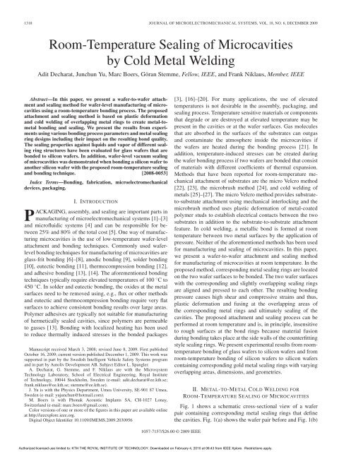
1318 JOURNAL OF MICROELECTROMECHANICAL SYSTEMS, VOL. 18, NO. 6, DECEMBER 2009<br />
Room-Temperature Sealing <strong>of</strong> Microcavities<br />
by Cold Metal Welding<br />
Adit Decharat, Junchun Yu, Marc Boers, Göran Stemme, Fellow, IEEE, and Frank Niklaus, Member, IEEE<br />
Abstract—In this paper, we present a wafer-to-wafer attachment<br />
and sealing method for wafer-level manufacturing <strong>of</strong> microcavities<br />
using a room-temperature bonding process. The proposed<br />
attachment and sealing method is based on plastic deformation<br />
and cold welding <strong>of</strong> overlapping metal rings to create metal-tometal<br />
bonding and sealing. We present the results from experiments<br />
using various bonding process parameters and metal sealing<br />
ring designs including their impact on the resulting bond quality.<br />
The sealing properties against liquids and vapor <strong>of</strong> different sealing<br />
ring structures have been evaluated for glass wafers that are<br />
bonded to silicon wafers. In addition, wafer-level vacuum sealing<br />
<strong>of</strong> microcavities was demonstrated when bonding a silicon wafer to<br />
another silicon wafer with the proposed room-temperature sealing<br />
and bonding technique. [2008-0053]<br />
Index Terms—Bonding, fabrication, microelectromechanical<br />
devices, <strong>packaging</strong>.<br />
I. INTRODUCTION<br />
PACKAGING, assembly, and sealing are important parts in<br />
manufacturing <strong>of</strong> microelectromechanical systems [1]–[3]<br />
and micr<strong>of</strong>luidic systems [4] and can be responsible for between<br />
25% and 80% <strong>of</strong> the total cost [5]. One way <strong>of</strong> manufacturing<br />
microcavities is the use <strong>of</strong> low-temperature wafer-level<br />
attachment and bonding techniques. Commonly used waferlevel<br />
bonding techniques for manufacturing <strong>of</strong> microcavities are<br />
glass-frit bonding [6]–[8], anodic bonding [9], solder bonding<br />
[10], eutectic bonding [11], thermocompression bonding [12],<br />
and adhesive bonding [13], [14]. The aforementioned bonding<br />
techniques typically require elevated temperatures <strong>of</strong> 100 ◦Cto 450 ◦C. In solder and eutectic bonding, the oxides at the metal<br />
surfaces need to be removed using, e.g., flux or other methods<br />
and eutectic and thermocompression bonding require very flat<br />
surfaces to achieve consistent bonding results over large areas.<br />
Polymer adhesives are typically not suitable for manufacturing<br />
<strong>of</strong> hermetically sealed cavities, since polymers are permeable<br />
to gasses [13]. Bonding with localized heating has been used<br />
to reduce thermally induced stresses in the bonded packages<br />
Manuscript received March 3, 2008; revised June 8, 2009. First published<br />
October 16, 2009; current version published December 1, 2009. This work was<br />
supported in part by the Swedish Intelligent Vehicle Safety Systems program<br />
and in part by Autoliv Development AB. Subject Editor L. Spangler.<br />
A. Decharat, G. Stemme, and F. Niklaus are with the Microsystem<br />
Technology Laboratory, <strong>School</strong> <strong>of</strong> <strong>Electrical</strong> <strong>Engineering</strong>, Royal Institute<br />
<strong>of</strong> Technology, 10044 Stockholm, Sweden (e-mail: adit.decharat@ee.kth.se;<br />
frank.niklaus@ee.kth.se; stemme@ee.kth.se).<br />
J. Yu is with the Physics Department, Umea University, SE-901 87 Umea,<br />
Sweden (e-mail: yujunchun@hotmail.com).<br />
M. Boers is with Phonak Acoustic Implants SA, CH-1027 Lonay,<br />
Switzerland (e-mail: marc.boers@gmail.com).<br />
Color versions <strong>of</strong> one or more <strong>of</strong> the figures in this paper are available online<br />
at http://ieeexplore.ieee.org.<br />
Digital Object Identifier 10.1109/JMEMS.2009.2030956<br />
1057-7157/$26.00 © 2009 IEEE<br />
[3], [16]–[20]. For many applications, the use <strong>of</strong> elevated<br />
temperatures is not desirable in the assembly, <strong>packaging</strong>, and<br />
sealing process. Temperature sensitive materials or components<br />
that degrade or are destroyed at elevated temperature may be<br />
present in the cavities or at the wafer surfaces. Gas molecules<br />
that are absorbed in the surfaces <strong>of</strong> the substrates can outgas<br />
and contaminate the atmosphere inside the microcavities if<br />
the wafers are heated during the bonding process [21]. In<br />
addition, temperature-induced stresses can be created during<br />
the wafer bonding process if two wafers are bonded that consist<br />
<strong>of</strong> materials with different coefficients <strong>of</strong> thermal expansion.<br />
Methods that have been reported for room-temperature mechanical<br />
attachment <strong>of</strong> substrates are the micro Velcro method<br />
[22], [23], the microbrush method [24], and cold welding <strong>of</strong><br />
metals [25]–[27]. The micro Velcro method provides substrateto-substrate<br />
attachment using mechanical interlocking and the<br />
microbrush method uses plastic deformation <strong>of</strong> metal-coated<br />
polymer studs to establish electrical contacts between the two<br />
substrates in addition to the substrate-to-substrate attachment<br />
feature. In cold welding, a metallic bond is formed at room<br />
temperature between two metal surfaces by the application <strong>of</strong><br />
pressure. Neither <strong>of</strong> the aforementioned methods has been used<br />
for manufacturing and sealing <strong>of</strong> microcavities. In this paper,<br />
we present a wafer-to-wafer attachment and sealing method<br />
for manufacturing <strong>of</strong> microcavities at room temperature. In the<br />
proposed method, corresponding metal sealing rings are located<br />
on the two wafer surfaces to be bonded. The two wafer surfaces<br />
with the corresponding and slightly overlapping sealing rings<br />
are aligned and pressed to each other. The resulting bonding<br />
pressure causes high shear and compressive strains and thus,<br />
plastic deformation and fusing at the overlapping areas <strong>of</strong><br />
the corresponding metal rings and ultimately sealing <strong>of</strong> the<br />
cavities. The proposed attachment and sealing process can be<br />
performed at room temperature and is, in principle, insensitive<br />
to rough surfaces at the bond rings because material fusion<br />
during bonding takes place at the side walls <strong>of</strong> the counterfitting<br />
style sealing rings. We present experimental results from roomtemperature<br />
bonding <strong>of</strong> glass wafers to silicon wafers and from<br />
room-temperature bonding <strong>of</strong> silicon wafers to silicon wafers<br />
containing corresponding gold metal sealing rings with varying<br />
overlapping areas, dimensions, and geometries.<br />
II. METAL-TO-METAL COLD WELDING FOR<br />
ROOM-TEMPERATURE SEALING OF MICROCAVITIES<br />
Fig. 1 shows a schematic cross-sectional view <strong>of</strong> a wafer<br />
pair containing corresponding metal sealing rings that define<br />
the cavities. Fig. 1(a) shows the wafer pair before and Fig. 1(b)<br />
Authorized licensed use limited to: KTH THE ROYAL INSTITUTE OF TECHNOLOGY. Downloaded on February 4, 2010 at 08:43 from IEEE Xplore. Restrictions apply.
DECHARAT et al.: ROOM-TEMPERATURE SEALING OF MICROCAVITIES BY COLD METAL WELDING 1319<br />
Fig. 1. Schematic cross-sectional view <strong>of</strong> the wafers with corresponding metal sealing rings (a) before and (b) after bonding.<br />
Fig. 2. (a) Top view <strong>of</strong> three types <strong>of</strong> microcavities with metal sealing rings on wafer 1 and corresponding metal sealing rings on the wafer 2. (b) Threedimensional<br />
view <strong>of</strong> the overlaying sealing rings <strong>of</strong> an aligned and bonded wafer pair.<br />
after the wafer pair is aligned and brought into contact. Fig. 2(a)<br />
shows a schematic top view <strong>of</strong> a first wafer with three different<br />
cavity structures containing 2, 3, and 5 metal sealing rings<br />
per cavity and the corresponding rings on the second wafer<br />
with 1, 2, and 4 metal sealing rings. When the wafers are<br />
properly aligned to each other, the corresponding metal sealing<br />
rings have small overlapping areas. The wafer pair is pressed<br />
together by applying a uniform force. As a result, the corresponding<br />
metal sealing rings wedge into each other, as shown<br />
in Figs. 1(b) and 2(b). This is due to the creation <strong>of</strong> large local<br />
shear and compressive strains at the overlapping edges <strong>of</strong> the<br />
metal sealing rings, resulting in localized plastic deformation<br />
and cold welding.<br />
The resulting bonded area that seals the cavities and holds<br />
the wafers together consists <strong>of</strong> the wedged overlapping areas <strong>of</strong><br />
the corresponding metal sealing rings. This area is very small<br />
in relation to the total wafer area and the forces to which the<br />
bond can be exposed by, e.g., wafer handling and dicing. To<br />
Fig. 3. Introduction <strong>of</strong> an underfill material in the gap in between the bonded<br />
wafer pair to reinforce the bond strength <strong>of</strong> the sealed bonds.<br />
reinforce the wafer bond, an underfill material (e.g., an underfill<br />
epoxy) can be introduced in the gap between the bonded wafer<br />
pair after the wafers are joined and the cavities are sealed, as<br />
shown in Fig. 3. The underfill material fills the gap between the<br />
wafers by capillary forces. Depending on the selected material,<br />
the hardening <strong>of</strong> the underfill material can be achieved at room<br />
temperature or at an increased curing temperature. The final<br />
Authorized licensed use limited to: KTH THE ROYAL INSTITUTE OF TECHNOLOGY. Downloaded on February 4, 2010 at 08:43 from IEEE Xplore. Restrictions apply.
1320 JOURNAL OF MICROELECTROMECHANICAL SYSTEMS, VOL. 18, NO. 6, DECEMBER 2009<br />
Fig. 4. (a) Cross-sectional pr<strong>of</strong>ile <strong>of</strong> the electroplated gold sealing rings with nominal dimensions (not to scale). (b) Cross-sectional SEM image <strong>of</strong> an<br />
electroplated gold sealing ring.<br />
bond strength is predominantly determined by the used underfill<br />
material.<br />
III. EXPERIMENTS<br />
A. Manufacturing <strong>of</strong> Sealing Rings<br />
In the experiments, electroplated gold was selected as metal<br />
for the sealing rings that define the microcavities because gold<br />
is a relative s<strong>of</strong>t and deformable material. The metal sealing<br />
rings are manufactured by sputtering a thin gold seed layer on<br />
the wafers. Next, a thick photoresist layer (> 30 μm) is coated<br />
and patterned, and thereby defines the areas for the sealing<br />
rings. Gold is electroplated at the areas where the photoresist is<br />
patterned (removed), and thus, the photoresist is functioning as<br />
a mold for the electroplated gold. Subsequently, the photoresist<br />
mold and the gold seed layer are removed with wet-etching<br />
processes, and the wafers are rinsed with deionized water and<br />
dried. Gold sealing rings with a height <strong>of</strong> 30 μm and a width<br />
<strong>of</strong> 50 μm have been used to define the microcavities. Fig. 4(a)<br />
shows a schematic cross section <strong>of</strong> an electroplated gold sealing<br />
ring pr<strong>of</strong>ile including the nominal dimensions, and Fig. 4(b)<br />
shows a scanning electron microscope (SEM) image <strong>of</strong> the<br />
cross section <strong>of</strong> an electroplated gold sealing ring. The convex<br />
side walls <strong>of</strong> the gold sealing ring origins from the patterning<br />
process <strong>of</strong> the positive photoresist mold. In principle, sealing<br />
rings with 90◦ angles or with concave side walls may also be<br />
suitable. The sealing rings for the microcavities are manufactured<br />
on 100-mm-diameter silicon and glass wafers. Each wafer<br />
pair contains 54 microcavities with different cavity shapes<br />
(rounded corners and squared corners), different cavity sizes<br />
(1000 μm × 3500 μm, 3500 μm × 3500 μm, and 8000 μm ×<br />
8000 μm), different numbers <strong>of</strong> sealing rings (2, 3, and 5 with<br />
matching 1, 2, and 4 sealing rings), and different overlapping<br />
lengths <strong>of</strong> the sealing rings (2, 3, 4, and 6 μm). The different<br />
cavity shapes and sizes are shown in Fig. 5. The overlapping<br />
lengths <strong>of</strong> the sealing rings, as shown in Fig. 1(b), are defined<br />
as the overlap (e.g., 2, 3, 4, or 6 μm) on each side <strong>of</strong> the upper<br />
outline <strong>of</strong> the sealing ring on one wafer with the upper outline<br />
<strong>of</strong> the corresponding sealing rings on the second wafer. The<br />
smallest overlapping length <strong>of</strong> 2 μm represents the best possible<br />
wafer-to-wafer alignment accuracy <strong>of</strong> the available alignment<br />
equipment. The total overlapping area <strong>of</strong> the gold sealing ring<br />
design used in the experiments are 12.78 · 10−6 m2 per wafer.<br />
Fig. 5. Evaluated cavity shapes and sizes with denotations. Measures are<br />
given in micrometers.<br />
The yield strength <strong>of</strong> gold has been reported to be on the order<br />
<strong>of</strong> 200 MPa [28]. The total required wafer bonding force to get<br />
plastic deformation in the overlapping gold sealing ring areas<br />
can be roughly estimated with F = σ · A, where σ is the stress<br />
and A is the total overlapping area <strong>of</strong> the corresponding sealing<br />
rings <strong>of</strong> the wafer pair.<br />
B. Wafer-Level Sealing <strong>of</strong> Cavities When Bonding Silicon<br />
Wafers to Glass Wafers<br />
A total <strong>of</strong> six silicon-glass wafer pairs have been bonded<br />
with the proposed room-temperature sealing and attachment<br />
method. The glass wafers are used in the experiments to be<br />
able to inspect and evaluate the sealing rings and the cavities<br />
after the wafer pairs are bonded. In four <strong>of</strong> the experiments, a<br />
500-μm-thick glass wafer was bonded to a 300-μm-thick<br />
double-sided polished silicon wafer. In two <strong>of</strong> the experiments,<br />
a 500-μm-thick glass wafer was bonded to a 500-μm-thick<br />
Authorized licensed use limited to: KTH THE ROYAL INSTITUTE OF TECHNOLOGY. Downloaded on February 4, 2010 at 08:43 from IEEE Xplore. Restrictions apply.
DECHARAT et al.: ROOM-TEMPERATURE SEALING OF MICROCAVITIES BY COLD METAL WELDING 1321<br />
Fig. 6. View through the top glass wafer at the bond interface <strong>of</strong> a cavity.<br />
Three sealing rings with rounded corners on the silicon wafer and the corresponding<br />
two sealing rings on the glass wafer are shown. The inside <strong>of</strong> the<br />
cavity contains color traces from IPA vapor that has penetrated the cavity during<br />
a gross-leak test.<br />
double-sided polished silicon wafer. The room-temperature<br />
wafer-to-wafer attachment (bonding) and cavity sealing is done<br />
in a standard commercial wafer bonder. Two wafers with corresponding<br />
sealing rings are aligned using commercial wafer-towafer<br />
alignment equipment. The alignment keys on the wafers<br />
can be observed through the transparent glass wafer. After<br />
alignment, the wafer pair is fixed on a standard bond fixture <strong>of</strong><br />
the wafer bonder with the spacers <strong>of</strong> the bond fixture separating<br />
the two wafers. The aligned wafers on the bond fixture are<br />
transferred to the bond chamber and the chamber is evacuated<br />
to a pressure <strong>of</strong> 10 −4 mbar. The wafers remain in the vacuum<br />
atmosphere for 1 h to remove excess moisture and gasses<br />
from the wafer surfaces before the wafers are joined inside the<br />
vacuum atmosphere by removing the spacers in between them.<br />
Next, a bond force <strong>of</strong> 2.5 kN is applied for 10 min to the wafer<br />
stack with the bond tool. Thereafter, the bond force is removed,<br />
the bond chamber is vented, and the bonded wafer pair is taken<br />
out <strong>of</strong> the bond chamber. All bonding steps are performed at<br />
room temperature.<br />
After the wafer-to-wafer attachment process, the sealing<br />
rings are inspected with an optical microscope through the glass<br />
wafers. For all bonded wafer pairs and cavity types, the integrity<br />
<strong>of</strong> the gold sealing rings remained intact. Even if the wafers<br />
were slightly misaligned (on the order <strong>of</strong> 2 to 3 μm) prior to<br />
the wafer-to-wafer attachment, the gold sealing rings wedge<br />
into each other. Fig. 6 shows an image, taken through the top<br />
glass wafer <strong>of</strong> a bonded wafer pair, on which two gold sealing<br />
rings that are wedged into three corresponding sealing rings can<br />
be seen. Fig. 7 shows an image, taken through the top glass<br />
wafer <strong>of</strong> a bonded wafer pair, in which gold sealing rings that<br />
have squared corners can be seen. At the squared corners <strong>of</strong> the<br />
cavities, small fractures are visible in the surface <strong>of</strong> the glass<br />
wafer underneath the gold sealing rings.<br />
Fig. 8 shows a cross-sectional SEM image <strong>of</strong> a diced sample<br />
<strong>of</strong> a bonded wafer pair. The image depicts the end <strong>of</strong> sealing<br />
ring evaluation structures consisting <strong>of</strong> three gold sealing rings<br />
on the lower silicon wafer (wafer 2) and two gold sealing rings<br />
on the upper glass wafer (wafer 1). The sealing ring structures<br />
consist <strong>of</strong> straight lines and do not form an enclosed cavity. The<br />
cut for the cross section is done a few micrometers apart from<br />
the end <strong>of</strong> the sealing ring structures in order not to affect or<br />
damage the structures during dicing. As expected, the sealing<br />
ring structures are plastically deformed and wedged into each<br />
other.<br />
Fig. 7. View through the top glass wafer at the bond interface <strong>of</strong> a cavity. Two<br />
sealing rings with squared corners on the silicon wafer and the corresponding<br />
two sealing rings on the glass wafer are shown. Fractures in the glass wafer<br />
surface at the cavity corner are indicated.<br />
All microcavities <strong>of</strong> two <strong>of</strong> the bonded silicon-glass wafer<br />
pairs were evaluated with a gross-leak test to investigate the<br />
cavity sealing. In the gross leak tests, isopropanol alcohol<br />
(IPA) is injected in the 30- to 40-μm-wide gap that exists<br />
between the bonded wafers. The gap fills with the liquid IPA by<br />
capillary forces. Liquid and vapor IPA can enter the cavities that<br />
contain gross leaks. Liquid and vapor leakage into the cavities<br />
is visually detected through the glass wafer. When performing<br />
the gross leak tests, a number <strong>of</strong> cavities were immediately<br />
filled with liquid IPA, indicating gross leaks in these cavities.<br />
Most cavities on the silicon-glass wafer pairs were penetrated<br />
by IPA vapor, which then condenses inside the cavities, as<br />
shown in Fig. 6. For a total <strong>of</strong> six <strong>of</strong> the cavities, no penetration<br />
with IPA vapor was observed, indicating good sealing <strong>of</strong> these<br />
cavities. Table I shows the cavity designs that have been sealed<br />
without detectable gross leaks. Of the sealed cavities, one is<br />
8000 μm × 8000 μm (type A), four are 3500 μm × 3500 μm<br />
(type B, E, and F), and one is 1000 μm × 3500 μm (type D),<br />
and all cavities have rounded corners. As can be seen in Table I,<br />
five <strong>of</strong> the sealed cavities have three sealing rings on one wafer<br />
and two corresponding sealing rings on the second wafer, and<br />
one <strong>of</strong> the sealed cavities has five sealing rings on one wafer and<br />
four corresponding sealing rings on the second wafer. Four <strong>of</strong><br />
the sealed cavities have sealing rings with overlapping lengths<br />
<strong>of</strong> 2 μm and two with overlapping lengths <strong>of</strong> 4 μm.<br />
In addition to the aforementioned described experiments, one<br />
bonded wafer pair was separated using force. The force needed<br />
to separate the wafers is comparably small. This is because<br />
the regions that hold the bonded wafers together are limited to<br />
the comparably small sealing ring areas. When inspecting the<br />
fractured bond interface at the sealing rings, it was observed<br />
that on most parts <strong>of</strong> the wafer, the gold sealing rings are broken<br />
away from the glass wafer and still remain bonded to the gold<br />
rings on the silicon wafer. Fig. 9 shows a top view <strong>of</strong> a bonded<br />
gold ring after the top glass wafer has been removed by force.<br />
A piece <strong>of</strong> glass that was broken out <strong>of</strong> the glass wafer remains<br />
bonded to the gold sealing ring that was originally positioned<br />
on the glass wafer. This indicates very good bonding and cold<br />
welding <strong>of</strong> the corresponding overlapping gold sealing rings<br />
due to plastic deformation <strong>of</strong> these areas.<br />
C. Wafer-Level Sealing <strong>of</strong> Cavities When Bonding Silicon<br />
Wafers to SOI Wafers<br />
A total <strong>of</strong> two silicon-SOI wafer pairs have been bonded<br />
with the proposed room-temperature sealing and attachment<br />
Authorized licensed use limited to: KTH THE ROYAL INSTITUTE OF TECHNOLOGY. Downloaded on February 4, 2010 at 08:43 from IEEE Xplore. Restrictions apply.
1322 JOURNAL OF MICROELECTROMECHANICAL SYSTEMS, VOL. 18, NO. 6, DECEMBER 2009<br />
Fig. 8. Cross-sectional SEM images with (a) counterfitting sealing ring structures that are wedged into each other and (b) close-up view <strong>of</strong> the interface <strong>of</strong> two<br />
counterfitting sealing ring structures.<br />
TABLE I<br />
SEALING RESULTS FROM THE GROSS LEAK EXPERIMENTS FOR CAVITIES WITH DIFFERENT SHAPES,<br />
SIZES, OVERLAP LENGTHS OF SEALING RINGS, AND NUMBER OF SEALING RINGS<br />
method. In both experiments, a 525-μm-thick SOI wafers was<br />
bonded to a 500-μm-thick double-sided polished silicon wafer.<br />
The silicon device layer <strong>of</strong> the SOI wafers is 20 μm thick,<br />
and the SiO2 layer is 1 μm thick. To be able to align the<br />
corresponding gold sealing rings on the nontransparent silicon<br />
and SOI wafers, a standard wafer-to-wafer alignment procedure<br />
is used that features wafer backside alignment keys together<br />
with digitized images. This is done using commercial waferto-wafer<br />
alignment equipment. After the wafer alignment, the<br />
wafer pair is fixed on the bond fixture <strong>of</strong> the wafer alignment<br />
equipment with the spacers from the bond fixture separating<br />
the two wafers. The aligned wafer pair on the bond fixture<br />
is transferred from the aligner to the bond chamber, and the<br />
chamber is evacuated to a pressure <strong>of</strong> 10 −4 mbar. The wafers<br />
remain in the vacuum atmosphere for 3 h to remove excess<br />
moisture and gasses from the wafer surfaces before the wafers<br />
are joined inside the vacuum atmosphere by removing the<br />
spacers. Next, the wafer stack is pressed together with the bond<br />
tool. Thereafter, the bond force is removed, the bond chamber is<br />
vented, and the bonded wafer pair is carefully taken out <strong>of</strong> the<br />
bond chamber. One wafer pair was pressed with a bond force<br />
<strong>of</strong> 2.5 kN for 10 min, and the second wafer pair was pressed<br />
with a bond force <strong>of</strong> 2.8 kN for 10 min. For both bonded wafer<br />
pairs, a low-viscosity two-component epoxy is introduced in<br />
between the gap <strong>of</strong> the wafers, as shown in Fig. 3. The twocomponent<br />
underfill epoxy cures at room temperature and reinforces<br />
the bond between the wafers at the corresponding sealing<br />
rings.<br />
Authorized licensed use limited to: KTH THE ROYAL INSTITUTE OF TECHNOLOGY. Downloaded on February 4, 2010 at 08:43 from IEEE Xplore. Restrictions apply.
DECHARAT et al.: ROOM-TEMPERATURE SEALING OF MICROCAVITIES BY COLD METAL WELDING 1323<br />
Fig. 9. Top view <strong>of</strong> a sealing ring section on the silicon wafer after bonding<br />
and subsequent forceful separation <strong>of</strong> the wafer pair. The gold ring from the<br />
glass wafer is remaining in between the gold rings on the silicon wafer. A glass<br />
piece that has been broken out <strong>of</strong> the glass wafer remains on the gold sealing<br />
ring from the glass wafer.<br />
Fig. 10. (a) Bulk silicon <strong>of</strong> the SOI wafer is thinned down with DRIE.<br />
(b) Differential pressures between the inside and the outside atmospheres <strong>of</strong><br />
the microcavity cause the thin silicon lid membranes to deflect.<br />
To estimate the pressure level <strong>of</strong> the encapsulated atmosphere<br />
inside the microcavities and to detect possible gross leaks, the<br />
bulk silicon <strong>of</strong> the SOI wafer is removed by deep reactive ion<br />
etching (DRIE) and using the SiO2 layers <strong>of</strong> the SOI wafers<br />
as the etch stop, as shown in Fig. 10(a) and (b). Thus, only<br />
the 20-μm-thick silicon device layer together with the 1-μmthick<br />
SiO2 layer remains as lid on the sealed cavities. If a<br />
pressure difference exists between the atmospheres inside and<br />
outside a cavity, the thin silicon membrane deflects, as shown<br />
in Fig. 10(b).<br />
After thinning the bulk silicon <strong>of</strong> the SOI wafer with DRIE<br />
from the wafer pair that was bonded with a bond force <strong>of</strong><br />
2.5 kN, about 50% <strong>of</strong> the membranes <strong>of</strong> the microcavities<br />
deflect strongly to the inside <strong>of</strong> the cavities. This indicates a<br />
significantly lower pressure inside these cavities as compared<br />
to the outside pressure. For all other cavities on this wafer, the<br />
20-μm-thin lid membranes were approximately leveled with a<br />
slight predeflection on the order <strong>of</strong> a few micrometers, most<br />
likely a result from the strain in the remaining SiO2 layer.<br />
Fig. 11 shows images <strong>of</strong> microcavities <strong>of</strong> types A, D, and E for<br />
which the membranes deflected to the inside <strong>of</strong> the cavities. It is<br />
shown in Fig. 11(a) that for the largest microcavity with a size<br />
<strong>of</strong> 8000 μm × 8000 μm (type A), the silicon membrane is deflected<br />
to an extent that it touches the bottom <strong>of</strong> the cavity. The<br />
Fig. 11. Images <strong>of</strong> sealed microcavities at atmospheric pressure with the lid<br />
membranes bending to the inside <strong>of</strong> the cavities. All successfully sealed cavities<br />
have rounded corners. The cavities are (a) type A (8000 μm × 8000 μm),<br />
(b) type D (1000 μm × 3500 μm), and (c) type E (3500 μm × 3500 μm).<br />
effective cavity height <strong>of</strong> this cavity has been measured with a<br />
pr<strong>of</strong>ilometer to be about 53 μm. This suggests that the wedging<br />
depth <strong>of</strong> the corresponding gold sealing rings for this cavity is<br />
on the order <strong>of</strong> 7 μm. None <strong>of</strong> the microcavity lid membranes <strong>of</strong><br />
the wafer pair bonded with a bond force <strong>of</strong> 2.8 kN are deflected<br />
after the bulk silicon <strong>of</strong> the SOI wafer was removed with DRIE.<br />
This indicates that none <strong>of</strong> the microcavities <strong>of</strong> this wafer are<br />
sealed.<br />
For an indicative estimate <strong>of</strong> the gas pressure inside the<br />
sealed cavities, they are placed in a vacuum chamber with a<br />
glass window. When decreasing the gas pressure in the vacuum<br />
chamber, the deflection <strong>of</strong> the cavity membranes decreases until<br />
the membranes level and then protrude to the outside <strong>of</strong> the<br />
cavities. Leveling <strong>of</strong> a cavity membrane happens when the<br />
pressure inside the cavity is on the same order as the pressure<br />
in the vacuum chamber. Leveling <strong>of</strong> the cavity membranes is<br />
detected by visual observation through the glass window <strong>of</strong><br />
the vacuum chamber. When lowering the gas pressure in the<br />
vacuum chamber, leveling <strong>of</strong> the cavity membranes happened<br />
for most sealed cavities at pressure levels on the order <strong>of</strong> 5 to<br />
10 mbar. For the microcavities with the lowest estimated gas<br />
pressures (type A), the membranes level at gas pressures below<br />
5 mbar. The pressure measurements have been repeated one<br />
month, three months, and six months after the sealing <strong>of</strong> the<br />
cavities. No detectable change in the vacuum pressures at which<br />
the cavity membranes level have been observed. However, it<br />
must be pointed out that the effective pressure differences<br />
between the inside and the outside <strong>of</strong> the microcavities are very<br />
small at the leveling point <strong>of</strong> the membranes. Thus, the visual<br />
detection <strong>of</strong> the cavity membrane deflection is not sufficiently<br />
accurate for reliable comparative measurements and provides<br />
only indicative estimates for the levels <strong>of</strong> the gas pressure<br />
inside the microcavities. A basic model for the deflection <strong>of</strong><br />
the cavity membrane has been used to verify the estimated<br />
pressure range inside the cavities. Cavity membranes are deflected<br />
by the difference in pressure ΔP between the outside<br />
<strong>of</strong> the cavities (atmospheric pressure Patm) and the inside <strong>of</strong><br />
the cavities (cavity pressure Pvac). Thus, the cavity pressure<br />
Authorized licensed use limited to: KTH THE ROYAL INSTITUTE OF TECHNOLOGY. Downloaded on February 4, 2010 at 08:43 from IEEE Xplore. Restrictions apply.
1324 JOURNAL OF MICROELECTROMECHANICAL SYSTEMS, VOL. 18, NO. 6, DECEMBER 2009<br />
relative to ambient atmospheric pressure can be estimated from<br />
Pvac = Patm − ΔP , where Patm = 1013 mbar. To estimate<br />
large load deflections <strong>of</strong> flat circular diaphragms (y0 < h/2),<br />
the analytical expression<br />
ΔPa4 =<br />
Eh4 16<br />
3(1 − μ2 yo 7 − μ<br />
+<br />
) h 3(1 − μ)<br />
can be used [29], where h is the membrane thickness, E is the<br />
Young’s modulus, μ is the Poisson’s ratio, a is the diaphragm<br />
radius, and y0 is the center deflection <strong>of</strong> the diaphragm. The<br />
resulting center deflection <strong>of</strong> the membranes from the circular<br />
cavities (type B, 3500-μm diameter) was measured with a<br />
pr<strong>of</strong>ilometer to be about 40 μm, excluding <strong>of</strong>fset deflection<br />
from the SiO2 strain. With a silicon membrane thickness <strong>of</strong><br />
20 μm (excluding the 1-μm-thick SiO2 layer), a Young’s<br />
modulus <strong>of</strong> 162 GPa, and a Poisson’s ratio <strong>of</strong> 0.22 [30], the<br />
estimated pressure difference ΔP can be calculated to be on<br />
the order <strong>of</strong> 970 mbar. Thus, the estimated gas pressure inside<br />
the cavity would be on the order <strong>of</strong> 40 mbar, which is in line<br />
with the estimates from the cavity membrane deflection inside<br />
a vacuum chamber.<br />
IV. DISCUSSION<br />
In the experiments, it was shown that the proposed roomtemperature<br />
wafer-to-wafer attachment and cavity sealing<br />
method works in principle. However, it was observed that<br />
localized fractures in glass wafers underneath the gold sealing<br />
rings can occur when bonding silicon wafers to glass wafers.<br />
Localized fractures underneath the gold sealing rings in the<br />
silicon wafers were not observed. It is believed that the large<br />
local stresses from the cold welding process near the overlapping<br />
areas <strong>of</strong> the gold sealing rings cause stress peaks in the<br />
glass that exceed its yield strength and, thus, cause the localized<br />
fractures <strong>of</strong> the glass. This is specifically the case for cavities<br />
with squared corners where the strain during bonding can<br />
aggregate at the squared corners, as shown in Fig. 6. The results<br />
from the experiments and the gross leak tests indicate that<br />
the main failure mechanism that causes the gross leaks in the<br />
experiments described in Table I are localized fractures <strong>of</strong> the<br />
glass wafers underneath the gold sealing rings due to excessive<br />
shear or compressive stresses. In the two bonding experiments<br />
in which silicon wafers were bonded to SOI wafers, the wafer<br />
pair that was bonded with the lower bonding force (lower strain<br />
in the sealing rings) achieved good sealing results (no gross<br />
leaks), while the wafer pair that was bonded with the higher<br />
bonding force did not achieve sealing <strong>of</strong> any <strong>of</strong> the cavities<br />
(contain gross leaks). The exact reason for this effect is not<br />
known. Possible explanations may be that the wafer pair was<br />
not sufficiently aligned before the wafer bonding step or the<br />
bonding force was too large and thus, causing local breakage<br />
<strong>of</strong> the silicon substrate material or delamination <strong>of</strong> the gold<br />
sealing rings from the silicon substrate surface due to excessive<br />
localized strain. It is interesting to point out that for the sealed<br />
microcavities, the wedging gold sealing rings penetrated each<br />
other only about 7 μm deep, which was sufficient to provide<br />
successful sealing without detectable gross leaks.<br />
y 3 o<br />
h 3<br />
(1)<br />
V. C ONCLUSION<br />
A room-temperature wafer attachment and sealing concept<br />
has been introduced and experimentally evaluated. Microcavities<br />
manufactured with this technique have been successfully<br />
sealed without detectable gross leaks. The shape <strong>of</strong> the cavities,<br />
the overlapping area <strong>of</strong> the sealing rings, and the wafer materials<br />
were found to influence the bonding and sealing results.<br />
REFERENCES<br />
[1] M. A. Schmidt, “Wafer-to-wafer bonding for microstructure formation,”<br />
Proc. IEEE, vol. 86, no. 8, pp. 1575–1585, Aug. 1998.<br />
[2] M. Esashi, “Wafer level <strong>packaging</strong> <strong>of</strong> MEMS,” J. Micromech. Microeng.,<br />
vol. 18, no. 7, pp. 1–13, Jul. 2008.<br />
[3] J. Mitchell and K. Najafi, “Localized back-side heating for lowtemperature<br />
wafer-level bonding,” in Proc. IEEE MEMS, Kobe,Japan,<br />
2007, pp. 377–380.<br />
[4] B. Ziaie, A. Baldi, M. Lei, Y. Gu, and R. A. Siegel, “Hard and s<strong>of</strong>t<br />
micromachining for BioMEMS: Review <strong>of</strong> techniques and examples <strong>of</strong><br />
applications in micr<strong>of</strong>luidics and drug delivery,” Adv. Drug Deliv. Rev.,<br />
vol. 56, no. 2, pp. 145–172, Feb. 2004.<br />
[5] L. Spangler, “Factors influencing the design <strong>of</strong> microsystems,” in Proc.<br />
IEEE Custom Integr. Circuits Conf., Orlando, FL, 2004, pp. 687–691.<br />
[6] J. E. Gragg, W. E. McCulley, W. B. Newton, and C. E. Derrington, “Compensation<br />
and calibration <strong>of</strong> a monolithic four terminal silicon pressure<br />
transducer,” in Proc. IEEE Solid-State Sens. Workshop, Hilton Head, SC,<br />
1984, pp. 21–27.<br />
[7] W. H. Ko, J. T. Suminto, and G. J. Yeh, “Bonding techniques for microsensors,”<br />
in Micromachining and Micro<strong>packaging</strong> <strong>of</strong> Transducers,<br />
C. D. Fung, P. W. Cheung, W. H. Ko, and D. G. Fleming, Eds.<br />
Amsterdam, The Netherlands: Elsevier, 1985, p. 41.<br />
[8] M. W. Judy, “Evolution <strong>of</strong> integrated inertial MEMS technology,” in Proc.<br />
Solid-State Sens., Actuators Microsyst. Workshop, Hilton Head, SC, 2004,<br />
pp. 27–32.<br />
[9] B. Lee, S. Seok, and K. Chun, “A study on wafer level vacuum <strong>packaging</strong><br />
for MEMS devices,” J. Micromech. Microeng., vol. 13, no. 5, pp. 663–<br />
669, Sep. 2003.<br />
[10] D. Sparks, G. Queen, R. Weston, G. Woodward, M. Putty, L. Jordan,<br />
S. Zarabadi, and K. Jayakar, “Wafer-to-wafer bonding <strong>of</strong> nonplanarized<br />
MEMS surfaces using solder,” J. Micromech. Microeng., vol. 11, no. 6,<br />
pp. 630–634, Nov. 2001.<br />
[11] R. F. Wolffenbuttel, “Low-temperature inter-mediate Au–Si wafer bonding;<br />
eutectic or silicide bond,” Sens. Actuators A, Phys., vol. 62, no. 1–3,<br />
pp. 680–686, Jul. 1997.<br />
[12] G.-S. Park, Y.-K. Kim, K.-K. Paek, J.-S. Kim, J.-H. Lee, and B.-K. Ju,<br />
“Low-temperature silicon wafer-scale thermocompression bonding using<br />
electroplated gold layers in hermetic <strong>packaging</strong>,” Electrochem. Solid-<br />
State Lett., vol. 8, no. 12, pp. G330–G332, 2005.<br />
[13] F. Niklaus, G. Stemme, J.-Q. Lu, and R. J. Gutmann, “Adhesive wafer<br />
bonding,” J. Appl. Phys., vol. 99, no. 3, pp. 031 101.1–031 101.28,<br />
Feb. 2006.<br />
[14] H. Kim and K. Najafi, “Characterization <strong>of</strong> low-temperature wafer bonding<br />
using thin-film parylene,” J. Microelectromech. Syst., vol. 14, no. 6,<br />
pp. 1347–1355, Dec. 2005.<br />
[15] R. K. Traeger, “Hermeticity <strong>of</strong> polymeric lid sealant,” in Proc. Electron.<br />
Compon. Conf., San Francisco, CA, 1976, pp. 361–367.<br />
[16] L. Lin, “MEMS post-<strong>packaging</strong> by localized heating and bonding,” IEEE<br />
Trans. Adv. Packag., vol. 23, no. 4, pp. 608–616, Nov. 2000.<br />
[17] Y. T. Cheng, L. Lin, and K. Najafi, “Localized silicon fusion and eutectic<br />
bonding for MEMS fabrication and <strong>packaging</strong>,” J. Microelectromech.<br />
Syst., vol. 9, no. 1, pp. 3–8, Mar. 2000.<br />
[18] Y.-T. Cheng, L. Lin, and K. Najafi, “A hermetic glass-silicon package<br />
formed using localized aluminum/silicon-glass bonding,” J. Microelectromech.<br />
Syst., vol. 10, no. 3, pp. 392–399, Sep. 2001.<br />
[19] Y.-T. Cheng, W.-T. Hsu, K. Najafi, C. T.-C. Nguyen, and L. Lin, “Vacuum<br />
<strong>packaging</strong> technology using localized aluminum/silicon-to-glass bonding,”<br />
J. Microelectromech. Syst., vol. 11, no. 5, pp. 556–565, Oct. 2002.<br />
[20] H. A. Yang, M. Wu, and W. Fang, “Localized induction heating solder<br />
bonding for wafer level MEMS <strong>packaging</strong>,” J. Micromech. Microeng.,<br />
vol. 15, no. 2, pp. 394–399, Feb. 2005.<br />
[21] R. C. Kullberg, “Processes and materials for creating and maintaining<br />
reliable vacuum and other controlled atmospheres in hermetically sealed<br />
MEMS packages,” in Proc. SPIE, Santa Clara, CA, 1999, vol. 3880,<br />
pp. 75–82.<br />
Authorized licensed use limited to: KTH THE ROYAL INSTITUTE OF TECHNOLOGY. Downloaded on February 4, 2010 at 08:43 from IEEE Xplore. Restrictions apply.
DECHARAT et al.: ROOM-TEMPERATURE SEALING OF MICROCAVITIES BY COLD METAL WELDING 1325<br />
[22] H. Han, L. E. Weiss, and M. L. Reed, “Mating and piercing mechanical<br />
structures for surface bonding applications,” in Proc. IEEE MEMS, Nara,<br />
Japan, 1991, pp. 253–258.<br />
[23] H. Han, L. E. Weiss, and M. L. Reed, “Micromechanical Velcro,”<br />
J. Microelectromech. Syst., vol. 1, no. 1, pp. 37–43, Mar. 1992.<br />
[24] S.-H. Lee, J. Chae, N. Yazdi, and K. Najafi, “Micro-brush press-on contact:<br />
A new technique for room temperature electrical and mechanical<br />
attachment,” in Proc. IEEE MEMS, Istanbul, Turkey, 2006, pp. 342–345.<br />
[25] A. Singh, D. A. Horsley, M. B. Cohn, A. P. Pisano, and R. T. Howe,<br />
“Batch transfer <strong>of</strong> microstructures using flip-chip solder bonding,” J.<br />
Microelectromech. Syst., vol. 8, no. 1, pp. 27–33, Mar. 1999.<br />
[26] C. Kim, M. Shtein, and S. R. Forrest, “Nanolithography based on patterned<br />
metal transfer and its application to organic electronic devices,”<br />
Appl. Phys. Lett., vol. 80, no. 21, pp. 4051–4053, May 2002.<br />
[27] W. Y. Zhang, G. S. Ferguson, and S. Tatic-Lucic, “Elastomer-supported<br />
cold welding for room temperature wafer-level bonding,” in Proc. MEMS,<br />
Maastricht, The Netherlands, 2004, pp. 741–744.<br />
[28] H. D. Espinosa and B. C. Prorok, “Effects <strong>of</strong> film thickness on the yielding<br />
behavior <strong>of</strong> polycrystalline gold films,” in Proc. MRS, 2002, vol. 695,<br />
pp. 349–354.<br />
[29] M. Giovanni, Flat and Corrugated Diaphragm Design Handbook. New<br />
York: Marcel Dekker, 1982.<br />
[30] B. Rashidian and M. G. Allen, “Electrothermal microactuators based on<br />
dielectric loss heating,” in Proc. IEEE Microelectromech. Syst. Workshop,<br />
Fort Lauderdale, FL, 1993, pp. 24–29.<br />
Adit Decharat received the M.Sc. degree in electrical<br />
engineering from King Mongkut’s Institute<br />
<strong>of</strong> Technology Ladkrabang, Bangkok, Thailand, in<br />
2002.<br />
In 2005, he joined the Department <strong>of</strong> <strong>Electrical</strong><br />
<strong>Engineering</strong>, Royal Institute <strong>of</strong> Technology,<br />
Stockholm, Sweden. His research interest is in<br />
MEMS integration and <strong>packaging</strong> for commercial<br />
IR cameras.<br />
Junchun Yu was born in Xiangtan, China, on<br />
July 17, 1983. He received the B.S. degree from<br />
Central South University, Changsha, China, and the<br />
M.S. degree in nanomaterials and nanotechnology<br />
from the Royal Institute <strong>of</strong> Technology, Stockholm,<br />
Sweden. He is currently working toward the Ph.D.<br />
degree in the Physics Department, Umea University,<br />
Umea, Sweden.<br />
Marc Boers received the M.S. degree in microengineering<br />
from Swiss Federal Institute <strong>of</strong> Technology,<br />
Lausanne, Switzerland, in 2006.<br />
During his M.S. studies, he served an internship at<br />
Microsystem Technology Group, Royal Institute <strong>of</strong><br />
Technology, Stockholm, Sweden, where he collaborated<br />
to develop a low-cost wafer-level-<strong>packaging</strong><br />
technology. He is currently a Development Engineer<br />
with the Phonak Acoustic Implants SA, Lonay,<br />
Switzerland, working in the medical industry on<br />
implantable hearing aid solutions.<br />
Göran Stemme (M’98–SM’04–F’06) received the<br />
M.Sc. degree in electrical engineering and the Ph.D.<br />
degree in solid-state electronics from Chalmers University<br />
<strong>of</strong> Technology, Gothenburg, Sweden, in 1981<br />
and 1987, respectively.<br />
In 1981, he joined the Department <strong>of</strong> Solid State<br />
Electronics, Chalmers University <strong>of</strong> Technology.<br />
There, in 1990, he became an Associate Pr<strong>of</strong>essor<br />
(docent) heading the silicon sensor research group.<br />
In 1991, he was appointed Pr<strong>of</strong>essor at the Royal<br />
Institute <strong>of</strong> Technology (KTH), Stockholm, Sweden,<br />
where he currently heads the Microsystem Technology Group, <strong>School</strong> <strong>of</strong><br />
<strong>Electrical</strong> <strong>Engineering</strong>. He has published more than 260 research journal and<br />
conference papers and has more than 22 patent proposals or granted patents.<br />
His research is devoted to microsystem technology based on micromachining<br />
<strong>of</strong> silicon.<br />
Dr. Stemme is a member <strong>of</strong> the Royal Swedish Academy <strong>of</strong> Sciences.<br />
Frank Niklaus (M’00) received the M.Sc. degree in<br />
mechanical engineering from the Technical University<br />
<strong>of</strong> Munich, Munich, Germany, in 1998, and the<br />
Ph.D. degree in MEMS from the Royal Institute <strong>of</strong><br />
Technology (KTH), Stockholm, Sweden, in 2002.<br />
He was working as a Consultant to industry and<br />
as a Visiting Scholar at Rensselaer Polytechnic Institute,<br />
Troy, NY, where he was working with 3-D IC<br />
technologies. He is currently an Associate Pr<strong>of</strong>essor<br />
in the Microsystem Technology Group, KTH, where<br />
he is the Team Leader for 3-D IC integrated MEMS<br />
and wafer-level <strong>packaging</strong> activities.<br />
Authorized licensed use limited to: KTH THE ROYAL INSTITUTE OF TECHNOLOGY. Downloaded on February 4, 2010 at 08:43 from IEEE Xplore. Restrictions apply.