etro lo g y - Carl Zeiss
etro lo g y - Carl Zeiss
etro lo g y - Carl Zeiss

Create successful ePaper yourself
Turn your PDF publications into a flip-book with our unique Google optimized e-Paper software.
Innovation<br />
The Magazine from <strong>Carl</strong> <strong>Zeiss</strong> – Special Edition<br />
8<br />
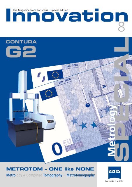
CONTURA<br />
G2<br />
METROTOM – ONE like NONE<br />
M<strong>etro</strong><strong>lo</strong>gy + Computed Tomography = M<strong>etro</strong>tomography<br />
M<strong>etro</strong><strong>lo</strong>gy<br />
SPECIAL<br />
We make it visible.
Preface<br />
Quality –<br />
Making a difference in g<strong>lo</strong>bal competition<br />
Dr. Rainer Ohnheiser,<br />
CEO <strong>Carl</strong> <strong>Zeiss</strong> Industrielle<br />
Messtechnik GmbH<br />
Valued customers and friends of<br />
<strong>Carl</strong> <strong>Zeiss</strong> Industrial M<strong>etro</strong><strong>lo</strong>gy:<br />
The current discussion in the area of production techno<strong>lo</strong>gy<br />
and m<strong>etro</strong><strong>lo</strong>gy is not about g<strong>lo</strong>bal competition as such, but<br />
how we handle this challenge and what we do with it.<br />
In addition to the issue of cost, quality is increasingly<br />
dominating the discussion: quality inherent in the final<br />
product, quality in individual components or parts, quality<br />
from the perspective of the supplier and customer.<br />
Inadequate quality, as well as inadequate documentation<br />
and verifiability of quality can lead to costly re-work and<br />
return of an entire shipment. Quality issues can also lead to<br />
costly and reputation damaging recalls which, more often<br />
than not, result in heavy financial <strong>lo</strong>sses for the companies<br />
involved.<br />
Quality must be measurable. Quality must be reproducible.<br />
Regardless of <strong>lo</strong>cation or type of procedure and equipment<br />
used to measure or inspect, ZEISS measuring techno<strong>lo</strong>gy<br />
and its systems deliver highly reproducible results that can<br />
mostly be attributed to the un-matched ZEISS scanning<br />
techno<strong>lo</strong>gy. ZEISS measuring results are trusted in the<br />
industrial arena so that both suppliers and end-users can<br />
rely on them.<br />
I believe we are starting a new value discussion in the field<br />
of measuring techno<strong>lo</strong>gy. The customer does not primarily<br />
decide in favor of a specific product, but the value of the<br />
decision itself is measured in terms of additional criteria:<br />
•<br />
•<br />
•<br />
•<br />
•<br />
Productivity and proximity to the shop f<strong>lo</strong>or and<br />
manufacturing processes<br />
The end-user’s acceptance of measuring results and<br />
protocols<br />
Error resistant applications through “expert know-how”<br />
Dependability and availability of the product throughout<br />
its <strong>lo</strong>ng life cycle, i.e., potential for expanding product<br />
capability through r<strong>etro</strong>fits<br />
Reliable m<strong>etro</strong><strong>lo</strong>gy suppliers who deliver cutting edge<br />
techno<strong>lo</strong>gy<br />
News<br />
Quality products<br />
at Control 2006<br />
At this year’s CONTROL, the leading show for<br />
m<strong>etro</strong><strong>lo</strong>gy, we present <strong>Carl</strong> <strong>Zeiss</strong> as a competent<br />
business partner and highlight future trends.<br />
With CONTURA G2, we introduce a platform<br />
which lends itself to the most varied applications<br />
and accommodates a broad sensor spectrum thereby<br />
meeting the current needs of the performance<br />
class. With this configuration, we appeal to a<br />
growing market segment of suppliers and mid-sized<br />
companies.<br />
We at <strong>Carl</strong> <strong>Zeiss</strong> M<strong>etro</strong><strong>lo</strong>gy are focused on delivering “more<br />
value” than merely delivering a product. Over 30 years of<br />
experience with CNC measuring machines; 18,000 CNC<br />
systems worldwide, 1 ,000 of those with scanning capability;<br />
over 5,000 machine configurations of the VAST and PRISMO<br />
product line; all these facts send a clear message. Service<br />
technicians and application engineers with the best training<br />
in the industry, as well as service and application centers<br />
with high-end equipment provide a consistent and clearly<br />
superior support structure worldwide.<br />
How do our customers benefit? How do we generate<br />
value for our customers?<br />
It is because of ZEISS measurement quality and ZEISS<br />
measurement protocols that your production results receive<br />
worldwide recognition and are reproducible.<br />
This techno<strong>lo</strong>gy enables any company to position itself at<br />
the top of the g<strong>lo</strong>bal market. ZEISS measuring techno<strong>lo</strong>gy<br />
will give you the advantage if you are purchasing workpieces<br />
from different suppliers; or are a supplier, i.e. to the<br />
automotive industry, with <strong>lo</strong>cal plants and facilities abroad;<br />
or if you are driving continuous process improvement.<br />
Quality makes a difference in g<strong>lo</strong>bal competition. By<br />
relying on ZEISS m<strong>etro</strong><strong>lo</strong>gy, you place your trust in a<br />
product leader and a reputable business partner. As a<br />
leader in performance and innovation, we help you build<br />
value for your company by delivering dependable products<br />
with a <strong>lo</strong>ng life cycle, as well as a reliable support network<br />
worldwide.<br />
We are <strong>lo</strong>oking forward to your visit and cordially invite you<br />
to be our guest at CONTROL 006.<br />
Dr. Rainer Ohnheiser<br />
Our leading CALYPSO and HOLOS software<br />
packages represent the established industry standard<br />
and even the benchmark for functionality and<br />
programmability.<br />
The computed tomography instrument M<strong>etro</strong>tom<br />
from <strong>Carl</strong> <strong>Zeiss</strong> introduces a new dimension of<br />
workpiece measurement techno<strong>lo</strong>gy: first rate<br />
measurement results within computed tomography<br />
coupled with ZEISS precision.<br />
With these techno<strong>lo</strong>gy highlights, ZEISS defines<br />
new frontiers at CONTROL 2006. We show the whole<br />
spectrum, encompassing both measuring techno<strong>lo</strong>gy<br />
for everyday use, as well as innovative advances for<br />
tomorrow’s applications.<br />
Innovation SPECIAL M<strong>etro</strong><strong>lo</strong>gy 8, 006
Preface<br />
Quality – Making a difference in g<strong>lo</strong>bal competition 2<br />
Contents/ Publisher‘s Imprint 3<br />
Product Report<br />
CONTURA G2 – The Easy Way to a New Measuring Machine 4<br />
Bernd Balle<br />
M<strong>etro</strong>tomography: Computed Tomography and M<strong>etro</strong><strong>lo</strong>gy 6<br />
Stephan Klumpp<br />
3D Scanning Ensures the Quality of Micro-parts 8<br />
Karl Seitz, Alfons Lindmayer<br />
Ultimate Performance Classes 10<br />
Nadine Kimmerle, Dietrich Imkamp<br />
MZ 2010 – The Latest in Measurement Counters 11<br />
Michael Knauer<br />
MMZ Machines Ensure Quality in Vehicle Construction 12<br />
Berndt Kammleiter<br />
MMZ Machines Ensure Quality in Energy Techno<strong>lo</strong>gy 13<br />
Berndt Kammleiter<br />
New Products for Inline M<strong>etro</strong><strong>lo</strong>gy 14<br />
Wolfgang Wiedmann, Hannes Daniel<br />
Accreditation for ISO 10360 16<br />
Ernst Wiedenmann<br />
Newsticker 17<br />
<strong>Carl</strong> <strong>Zeiss</strong> Introduces G<strong>lo</strong>bal Software Licensing 18<br />
Christina Scheible<br />
CALYPSO – The Software for Everyone 20<br />
Otto Boucky<br />
CAD Offline Programming under CALYPSO 22<br />
Josef Pfeilmeier, Michael Wieler<br />
CALYPSO Renews Old Measuring Techno<strong>lo</strong>gy 24<br />
Lutz Karras, Christoph Grieser<br />
CALYPSO on non-ZEISS Machines 25<br />
Lutz Karras, Christoph Grieser<br />
Operating Data Capture for Coordinate Measuring Machines 26<br />
Robert R. Roithmeier<br />
πWeb Small Business – The Solution for Mid-size Companies 28<br />
Andreas Lotze, Claudia Krönicke, Christina Scheible<br />
The Application Determines the Sensor – VAST 30<br />
Dietrich Imkamp, Karl Schepperle<br />
LineScan – Optical Scanning from Tomorrow Today 34<br />
Ralf Stecher<br />
<strong>Carl</strong> <strong>Zeiss</strong> Makes It Easier: Switch to Active Scanning 35<br />
Günter Keck<br />
Publisher‘s Imprint<br />
Innovation SPECIAL M<strong>etro</strong><strong>lo</strong>gy Nr. 8,<br />
the Magazin from <strong>Carl</strong> <strong>Zeiss</strong>, Mai 006<br />
Publisher: <strong>Carl</strong> <strong>Zeiss</strong> IMT GmbH, Oberkochen.<br />
Editor in chief: Alfons Lindmayer (responsible)<br />
<strong>Carl</strong> <strong>Zeiss</strong>, D-73446 Oberkochen, Department I-VM<br />
Phone (+7364)/ 03539, Telefax (+7364)/ 04657,<br />
e-mail: lindmayer@zeiss.de (Germany)<br />
Internet: www.zeiss.de.imt<br />
Editor and Layout: Nadine Kimmerle<br />
<strong>Carl</strong> <strong>Zeiss</strong>, D-73446 Oberkochen, Department I-VM<br />
From Users for Users<br />
CONTURA G2 – Quality Assurance on the Shop F<strong>lo</strong>or 36<br />
Felix Hoben<br />
Round-the-C<strong>lo</strong>ck CMM Precision Proves<br />
Essential to Company Success 38<br />
Annette Smith<br />
VW Saxony: Coordinate Measuring Systems<br />
for TSI Engines Ready in Record Time 40<br />
Matthias Kurth, Heinz-Günter Hoppe<br />
GageMax – the Flexible Measuring Innovation<br />
in Differential Bevel Gear Production 44<br />
Frank Lamberty, Peter Bachem, Theo Sannig,<br />
Rainer Detzel, Roger Bayer<br />
OVCMM Enables Efficient Determination<br />
of Measuring Uncertainty 46<br />
Björn B<strong>lo</strong>m, Josef Wanner<br />
DaimlerChrysler Chooses CALYPSO 48<br />
Kai Gläsner, Günter Keck<br />
Highly Accurate Gear Tooth Measurements<br />
in the Production Environment 49<br />
Roman Groß<br />
Minutes not Hours 50<br />
Rolf Bü<strong>lo</strong>w<br />
Pioneering Techno<strong>lo</strong>gy Common-Rail-Systems 52<br />
Szabolcs Jakob, Jozsef Beke, Christina Riedl, Markus Walcz<br />
Quality Assurance at BANG & OLUFSEN in Struer 54<br />
Jens Lynge Petersen, Peder Bay, Wolfgang Schwarz<br />
About us<br />
Techno<strong>lo</strong>gy Day in Brazil 56<br />
Antonio Car<strong>lo</strong>s Coelho, Janaina Iziquiel<br />
Under the Indian Sun 57<br />
Wolfgang Wiedmann, Hannes Daniel<br />
“IMT Practice Workpiece” 58<br />
Bernd Georgi<br />
Product Names and registered trademarks<br />
from <strong>Carl</strong> <strong>Zeiss</strong> IMT GmbH 59<br />
© 006, <strong>Carl</strong> <strong>Zeiss</strong> Industrielle Messtechnik GmbH, Oberkochen<br />
Permission for the reproduction of individual articles and<br />
illustrations from ”Innovation” – with due reference to the<br />
source – will gladly be granted after prior consultations<br />
with the editors.<br />
Picture sources: unless otherwise specified, all photographs<br />
were contributed by the authors or originate in the archives<br />
of <strong>Carl</strong> <strong>Zeiss</strong>.<br />
Authors: if no information is given to the contrary, the<br />
authors of the articles are emp<strong>lo</strong>yees of <strong>Carl</strong> <strong>Zeiss</strong> and<br />
can be contacted via the editor.<br />
Contents<br />
Innovation SPECIAL M<strong>etro</strong><strong>lo</strong>gy 8, 006 3
Product Report<br />
CONTURA G2 – The Easy Way to a<br />
New Measuring Machine from <strong>Carl</strong> <strong>Zeiss</strong><br />
Bernd Balle<br />
4<br />
CONTURA G2 is the next generation<br />
customized scanning platform for<br />
small and mid-size companies.<br />
With CONTURA G2, total scanning<br />
techno<strong>lo</strong>gy from <strong>Carl</strong> <strong>Zeiss</strong> is<br />
available for the first time in the<br />
mid-range price class.<br />
The traditional compromise of having<br />
to decide between touch-trigger or<br />
scanning for cost reasons is no <strong>lo</strong>nger<br />
an issue. With CONTURA G , scanning<br />
as basis of all measuring solutions is<br />
now available to everyone.<br />
The measuring task<br />
determines the<br />
optimum sensor<br />
for your solution<br />
The selection of a sensor should<br />
not be determined by the available<br />
CMM options of the manufacturer,<br />
but rather by the measuring task<br />
itself. If workpiece features contain<br />
many angles, sensor equipment with<br />
an articulating probe holder is often<br />
recommended. An active central sensor<br />
is the optimal setup for all traditional<br />
workpieces that are processed on three<br />
sides. CONTURA G offers a sensor for<br />
* Packages and Offerings may differ by Market<br />
each measuring methodo<strong>lo</strong>gy – without<br />
compromising the measuring accuracy.<br />
It offers the identical high measuring<br />
accuracy both in the version with the<br />
articulating probe head as well as with<br />
active scanning techno<strong>lo</strong>gy with the<br />
central probe. Measuring uncertainty<br />
and price are no <strong>lo</strong>nger determined by<br />
the type of sensor, but by the machine<br />
platform.<br />
At the same time, we offer<br />
completely new approaches to<br />
purchasing a machine, including the<br />
traditional purchase, full-time leasing<br />
or even pay by use. Return or trade<br />
in? With this machine, <strong>Carl</strong> <strong>Zeiss</strong> is not<br />
only branching off into new directions<br />
from a technical standpoint, but also is<br />
offering several purchasing options.<br />
Pay by Use*<br />
The unique program from <strong>Carl</strong> <strong>Zeiss</strong><br />
for CONTURA G offers maximum<br />
flexibility.<br />
Pay by use al<strong>lo</strong>ws you to get the<br />
benefits of a CONTURA G without<br />
having a budget. The most attractive<br />
point here is the lack of a purchase price.<br />
With a 1 -month leasing contract, you<br />
pay only a minimal per-hour usage<br />
fee for each hour that you use the<br />
CONTURA G . The only requirement<br />
is a minimum operation time of for<br />
example 800 hours per year. After the<br />
contract expires, you have the option<br />
of purchasing the measuring machine<br />
or returning it to <strong>Carl</strong> <strong>Zeiss</strong>.<br />
No-risk purchase*<br />
The no-risk purchase option makes<br />
the decision to invest very easy. <strong>Carl</strong><br />
<strong>Zeiss</strong> guarantees an unlimited right of<br />
return for the full purchase without a<br />
reason within the first six months of<br />
ownership. The no-risk purchase al<strong>lo</strong>ws<br />
you to trade in your CONTURA G<br />
within one year for a similar or higher<br />
quality <strong>Carl</strong> <strong>Zeiss</strong> measuring machine,<br />
enabling you to adjust to any changes<br />
in your range of tasks.<br />
True warranty*<br />
Where other manufactures only<br />
provide a partial warranty and simply<br />
exclude buy-out components, e.g.<br />
sensors, <strong>Carl</strong> <strong>Zeiss</strong> offers a true warranty<br />
for the entire system.<br />
Three versions of the<br />
new CONTURA G2:<br />
CONTURA G2 RDS<br />
CONTURA G RDS is designed for<br />
measuring complex features and parts<br />
with multiple angles requiring smaller<br />
styli. With 0,736 angular positions,<br />
the proven ZEISS RDS articulating<br />
probe holder reaches every position –<br />
even with the most complex workpiece<br />
geometries. VAST XXT can be used<br />
with styli up to 50mm <strong>lo</strong>ng, as well<br />
as very small styli with tip diameters<br />
of 0.3 mm. The large deflection range<br />
and the <strong>lo</strong>w measuring force make this<br />
machine a very sturdy scanning sensor.<br />
Innovation SPECIAL M<strong>etro</strong><strong>lo</strong>gy 8, 006
CONTURA G2 aktive<br />
This CMM is ideal for workpieces<br />
with features in the 6 main planes.<br />
Thus, the central sensor is the<br />
general solution for almost any task.<br />
Measuring deep features, in particular,<br />
can be optimally completed with <strong>lo</strong>ng<br />
extensions. It is available with the<br />
high-performance DynaTouch sensor<br />
for active single-point measuring and<br />
with the VAST XT scanning sensor for<br />
multi-point measurements of size, form<br />
and position. VAST XT offers active<br />
scanning and single-point measuring.<br />
Its high-speed and high-point density<br />
capabilities make VAST XT suitable for<br />
all applications in geometric, curve and<br />
freeform measuring, as well as reverse<br />
engineering. It can be equipped with<br />
extensions up to 500 mm and stylus<br />
weights up to 500 g.<br />
CONTURA G2 direkt<br />
The entry-level machine for<br />
scanning techno<strong>lo</strong>gy from <strong>Carl</strong> <strong>Zeiss</strong><br />
– for measuring geometry, form<br />
AND position — true ZEISS scanning.<br />
Equipped with the VAST XXT scanning<br />
sensor, this machine can already<br />
measure a large number of workpieces.<br />
For example, applications in which<br />
small single styli or star probes are<br />
sufficient. Ideal applications for this<br />
line include small parts with standard,<br />
squared geometries without slanted<br />
geometric features, and production<br />
progress checks of single processing<br />
steps.<br />
CONTURA G models offer X, Y, and<br />
Z measuring ranges of 700 x 700 x<br />
600 mm up to 1000 x 100 x 600 mm.<br />
All versions are equipped with the Ushaped<br />
granite table that expands the<br />
effective measuring range of the Z axis<br />
to 800 mm.<br />
CALYPSO and scanning<br />
Measuring runs can be easily<br />
generated using CALYPSO with Visual<br />
M<strong>etro</strong><strong>lo</strong>gy. The essential features make<br />
it the ideal software for your measuring<br />
requirements:<br />
•<br />
•<br />
•<br />
•<br />
•<br />
Object-oriented programming for<br />
the easiest generation of measuring<br />
runs using the same features that<br />
are also used in the design drawing.<br />
Easy generation of partial measuring<br />
runs from entire CNC programs.<br />
Simple changes, modifications, or<br />
additions to existing measurement<br />
programs.<br />
Software and sensor flexibility: from<br />
single-point measuring to scanning<br />
and optical measuring tasks.<br />
Application-specific display of the<br />
measurement results. Reports can<br />
be easily tai<strong>lo</strong>red to individual<br />
requirements.<br />
Whether for single-point measuring<br />
or scanning, manual or CNC, on a<br />
measuring machine or offline, touchtrigger<br />
or optical, standard geometric<br />
forms or freeform surfaces – with<br />
CALYPSO you do not need other<br />
software.<br />
True scanning<br />
ZEISS scanning is unparalleled.<br />
All relevant elements of a scanning<br />
system are deve<strong>lo</strong>ped and produced<br />
in-house: software, controller, sensors<br />
and calibration procedures. No other<br />
manufacturer can provide the <strong>Carl</strong><br />
<strong>Zeiss</strong> IMT scanning experience.<br />
Finally, the no-risk purchase is a key<br />
reason to buy a machine from <strong>Carl</strong><br />
<strong>Zeiss</strong>.<br />
Bernd Balle<br />
Marketing/ Business Strategy<br />
Innovation SPECIAL M<strong>etro</strong><strong>lo</strong>gy 8, 006 5
M<strong>etro</strong>tomography: Computed Tomography<br />
and M<strong>etro</strong><strong>lo</strong>gy in One<br />
Stephan Klumpp<br />
Fig. 1:<br />
The new ZEISS M<strong>etro</strong>tom<br />
instrument<br />
6<br />
The term m<strong>etro</strong>tomography is the<br />
result of combining m<strong>etro</strong><strong>lo</strong>gy<br />
and tomography. The fusion of<br />
industrial m<strong>etro</strong><strong>lo</strong>gy and industrial<br />
computed tomography (CT) will<br />
present comprehensive quality<br />
assurance with even more unknown<br />
possibilities.<br />
As a supplement to traditional<br />
techno<strong>lo</strong>gies in testing and measuring<br />
techno<strong>lo</strong>gy, industrial computed<br />
tomography is conquering new fields<br />
of application with fascinating and<br />
very productive solutions.<br />
The possibility of completely<br />
capturing a part and thus assessing<br />
the interior and exterior provides the<br />
user with all evaluation possibilities<br />
at a glance – within a short time and<br />
without destroying the component.<br />
<strong>Carl</strong> <strong>Zeiss</strong> 3D M<strong>etro</strong><strong>lo</strong>gy Services<br />
GmbH in Aalen, Germany performs a<br />
fast-growing number of CT services<br />
for a wide variety of applications<br />
in industrial testing and measuring<br />
techno<strong>lo</strong>gy.<br />
Customers are amazed at the results<br />
and the simple methodo<strong>lo</strong>gy.<br />
M<strong>etro</strong>tomography<br />
applications<br />
The main applications are concentrated<br />
in the fol<strong>lo</strong>wing areas:<br />
•<br />
•<br />
•<br />
•<br />
Destruction-free testing:<br />
- Defect checks<br />
- Porosity analyses<br />
- Assembly inspection<br />
- Damage analysis<br />
- Inspection of materials<br />
Dimensional m<strong>etro</strong><strong>lo</strong>gy<br />
Reverse engineering<br />
Comparison of geometries<br />
Potential<br />
and challenge<br />
Techno<strong>lo</strong>gists for m<strong>etro</strong><strong>lo</strong>gy and<br />
m<strong>etro</strong>tomography at <strong>Carl</strong> <strong>Zeiss</strong>, Dr.<br />
Dietrich Imkamp and Dr. Hubert<br />
Lettenbauer, summarize the challenges<br />
of m<strong>etro</strong>tomography as fol<strong>lo</strong>ws:<br />
“Dimensional measuring is more than<br />
just quantifying 3D image data. The<br />
quality of this data, the result of a CT<br />
scan in this case, largely depends on the<br />
quality of the entire chain of recording<br />
and thus from several parameters<br />
(size of the focal point, stability of the<br />
tube voltage, quality of the overall<br />
kinematics, etc.). Mastering this chain,<br />
as well as suitable calibration methods,<br />
is the first step in creating high-quality<br />
image data.”<br />
The same applies to the subsequent<br />
evaluation of the data. The orientation<br />
of the object according to the drawing,<br />
the inspection of form and position<br />
and the determination of curve gaps<br />
or the display of surface forms in<br />
accordance with DIN are everyday<br />
tasks in coordinate m<strong>etro</strong><strong>lo</strong>gy.<br />
All these demands apply to CT, the<br />
same as with traditional measuring<br />
equipment. However, the deciding<br />
factor for users is reliable information<br />
on whether the measured features of<br />
their part to be measured are within<br />
specified tolerances nor not. Trusting<br />
any results without verification of<br />
measuring system analysis is not only<br />
negligent regarding the quality of the<br />
product to be measured. 3D CT would<br />
also <strong>lo</strong>se acceptance at an early stage<br />
of its deve<strong>lo</strong>pment as specialists usually<br />
recognize such deficits quickly.<br />
Only someone able to master the<br />
entire measuring chain is capable of<br />
delivering and verifying reliable and<br />
reproducible results. The benefit to<br />
the user from the CT data is significant<br />
and offers enormous potential for the<br />
future of this techno<strong>lo</strong>gy.<br />
Innovation SPECIAL M<strong>etro</strong><strong>lo</strong>gy 8, 006
Fig. 2:<br />
All-around quality assurance<br />
Fig. 3:<br />
An applications technician for over six years, Stephan<br />
Tomaschko knows the CT system very well<br />
The future of<br />
m<strong>etro</strong>tomography<br />
Having innovative techno<strong>lo</strong>gies that<br />
are easily, quickly, productively and<br />
economically implemented is the most<br />
important aspect for users.<br />
An experienced team in testing and<br />
measuring techno<strong>lo</strong>gy is responsible<br />
for extensive product deve<strong>lo</strong>pment<br />
and application optimization of<br />
m<strong>etro</strong>tomography instruments at <strong>Carl</strong><br />
<strong>Zeiss</strong> IMT GmbH. The CT services team<br />
at <strong>Carl</strong> <strong>Zeiss</strong> 3D M<strong>etro</strong><strong>lo</strong>gy Services<br />
headed by Stephan Tomaschko has<br />
the largest wealth of experience in<br />
industrial CT services.<br />
Furthermore, <strong>Carl</strong> <strong>Zeiss</strong> has stood<br />
for innovative m<strong>etro</strong><strong>lo</strong>gy products,<br />
superior benefit to the customer and<br />
leading productivity for years. For<br />
innovative quality assurers, leading<br />
opinion makers and trendsetters, the<br />
near future will be clearly all about<br />
dealing with the applications as well<br />
as the influences and limitations of<br />
techno<strong>lo</strong>gy.<br />
CT services<br />
<strong>Carl</strong> <strong>Zeiss</strong> 3D has an applications<br />
system available for industrial CT<br />
measurements. The customer receives<br />
the evaluation of the measuring results<br />
in the form of a measurement <strong>lo</strong>g,<br />
deviation diagram or images depending<br />
on the task and the customer’s<br />
request. Detailed 3D data can be<br />
processed based on three-dimensional<br />
models or videos, for example, which<br />
graphically display the interior of the<br />
workpiece. For a comparison of a real<br />
workpiece with available CAD data,<br />
<strong>Carl</strong> <strong>Zeiss</strong> 3D also offers a “false co<strong>lo</strong>r<br />
image” that vividly documents the<br />
deviations between the nominal and<br />
actual values. Additionally, there is still<br />
a variety of evaluation possibilities that<br />
can be easily tai<strong>lo</strong>red to the customer.<br />
MBA Stephan Klumpp<br />
Head of Product Management M<strong>etro</strong>tomography<br />
M<strong>etro</strong>tomography<br />
With m<strong>etro</strong>tomography, it is now possible to nondestructively<br />
measure and make visible features and<br />
structures from the interior of “materials and parts”<br />
e.g. material defects (cracks, bubbles, gas porosities<br />
and inclusions) as well as internal workpiece features<br />
or geometries that cannot be probed. The preferred<br />
application of this techno<strong>lo</strong>gy is in the entire<br />
plastic injection techno<strong>lo</strong>gy, the production of cast<br />
parts, particularly cast aluminum, and in composite<br />
materials.<br />
Innovation SPECIAL M<strong>etro</strong><strong>lo</strong>gy 8, 006 7
3D Scanning Ensures<br />
the Quality of Micro-parts<br />
Karl Seitz, Alfons Lindmayer<br />
Fig. 1:<br />
Scanning sensors to<br />
measure tiny parts<br />
8<br />
Micro-parts are the key elements<br />
in components for medical devices,<br />
measuring machines and cars.<br />
Thanks to their surface qualities and<br />
exact dimensions, these tiny parts<br />
ensure smooth operation despite<br />
often extreme demands. The first<br />
step is the highly precise production,<br />
fol<strong>lo</strong>wed by efficient quality<br />
assurance. Scanning is becoming<br />
increasingly important.<br />
More and more applications require<br />
micro-components. They are essential<br />
to miniaturized systems such as<br />
pressure sensors, micro-motors and<br />
switches, drives, pumps, ball bearings<br />
and bio reactors, which are used in<br />
medical and m<strong>etro</strong><strong>lo</strong>gy equipment, as<br />
well as in motor vehicles. For example,<br />
micro-parts keep the high-speed drill<br />
at the dentist up and running. They<br />
ensure the required performance in the<br />
injection regulator of a turbo diesel.<br />
The micro-mechanical manufacturing<br />
process had to be enhanced as fast<br />
as new application possibilities<br />
appeared. This is especially valid for<br />
accuracy, reliability and productivity.<br />
Micro injection molding and milling,<br />
micro-bores and eroding enable the<br />
fully automated production of these<br />
tiny parts. Their geometric structures<br />
measure only a few tenths of a<br />
millimeter. The accuracy with which<br />
they are manufactured is less than one<br />
micron.<br />
Ensuring sustained, problem-free<br />
operation a<strong>lo</strong>ne would require the<br />
quality assurance of micro-parts<br />
– primarily in medical techno<strong>lo</strong>gy.<br />
Efficient quality assurance, however,<br />
is also necessary for economical<br />
production. Only reliable quantification<br />
with suitable measuring equipment of<br />
the geometric product features that<br />
determine quality, helps to reduce or<br />
avoid defects or the results of defects<br />
which endanger success. Technical and<br />
economical factors determine whether<br />
or not a measuring system is suitable<br />
for monitoring the manufacturing<br />
process. The measuring equipment<br />
used for quality assurance must be<br />
able to capture all features of a micropart<br />
relevant to the function with the<br />
required measuring uncertainty and<br />
minimal effort.<br />
Measuring micro-parts<br />
with touch sensors<br />
As with macro-parts, the vertical<br />
walls of micro-parts can also not be<br />
captured optically. Tactile coordinate<br />
m<strong>etro</strong><strong>lo</strong>gy is often the only technically<br />
suitable and economical solution.<br />
Coordinate measuring machines<br />
have been used for years as flexible,<br />
highly efficient measuring systems for<br />
the geometric quality assurance of<br />
traditional mechanical components.<br />
What has proven successful there<br />
– determining size, form and position<br />
through single-point measurement and<br />
Scanning – can also be generally used<br />
for the quality assurance of micro-parts.<br />
However, extremely small dimensions<br />
and different forces exist here; other<br />
principles apply. Consequently, the<br />
requirements on a measuring machine<br />
for micro-system techno<strong>lo</strong>gy are<br />
completely different than those on its<br />
“colleagues” in automobile production<br />
or tool making.<br />
Positioning and fixing micro-parts<br />
requires highly precise equipment. At<br />
the same time, the holding force must<br />
be very <strong>lo</strong>w to ensure that a micro-part<br />
is not deformed or damaged during<br />
the measurement. This necessitates<br />
a sensor system that must work with<br />
extremely <strong>lo</strong>w measuring forces, to guar<br />
that the micro-part is not deformed<br />
or moved by the machine when it is<br />
measured with touch sensors.<br />
CAD-based software is essential for<br />
multi-dimensional measuring tasks<br />
on micro-parts. As the features on<br />
micro-parts are practically invisible to<br />
the naked eye, the control data and<br />
measuring program should be directly<br />
programmed in the CAD module<br />
and remotely tested for interfering<br />
contours and travel paths before the<br />
measurement. This ensures that all<br />
features can be reached by the minute<br />
stylus without a collision. Featureguided<br />
and object-oriented software<br />
enables you to select and run any<br />
number of features from the entire<br />
measurement program – a decisive<br />
advantage with detailed measurements<br />
on micro-parts.<br />
F25: touch<br />
measurements with<br />
7.8 nm resolution<br />
The F 5 3D coordinate measuring<br />
machine with CALYPSO measuring<br />
software offers the above-mentioned<br />
possibilities. The measuring volume<br />
of the F 5 is one cubic decimeter.<br />
This is almost nothing compared to<br />
its “big brothers” in control and tool<br />
manufacturing process for example.<br />
Measuring uncertainty for this<br />
volume is 50 nm at a resolution of<br />
7.8 nm. Using minimal probe forces,<br />
this resolution, a<strong>lo</strong>ng with optimum<br />
control of the linear drives, enables<br />
touch measurements even in bores<br />
less than one millimeter in diameter.<br />
The basic precision kinematics were<br />
deve<strong>lo</strong>ped in cooperation with the<br />
Institute of M<strong>etro</strong><strong>lo</strong>gy and Techno<strong>lo</strong>gy<br />
(NMI) at the Technical University of<br />
Eindhoven, Netherlands as part of a<br />
doctorate project. It is based on the<br />
Abbe comparator principle.<br />
The touch, passive scanning sensor<br />
consists essentially of a scanning solid-<br />
Innovation SPECIAL M<strong>etro</strong><strong>lo</strong>gy 8, 006
Fig. 2:<br />
F25 measuring machine with new award-winning design<br />
state joint probe based on a silicon chip<br />
with integrated Piezo resistive elements.<br />
Deve<strong>lo</strong>ped in a joint effort with the<br />
Institute for Microsystem techno<strong>lo</strong>gy<br />
(IMTEK) in Freiburg, Germany, it works<br />
with resolution of one thousandth of<br />
a micron and is designed as a flexible<br />
changer. Single-point measuring and<br />
scanning are both possible. The sensor<br />
is designed for stylus diameters of 0<br />
to 500 microns at a free shaft length<br />
of up to 4 millimeters. Stylus tips can<br />
have a diameter between 50 and 700<br />
microns. A 50 mm <strong>lo</strong>ng match with<br />
a 5 mm diameter head is a giant in<br />
comparison.<br />
The probe forces were also reduced to<br />
less than 0.5 millinewtons per micron. As<br />
a supplement to touch measurements,<br />
an optical sensor, whose optics have<br />
been optimized and adjusted based on<br />
microscope objective, is used for D<br />
measurements. An additional camera<br />
aids visualization when probing the<br />
miniaturized features, thus simplifying<br />
learn programming.<br />
The future: inline<br />
process control<br />
The F 5 will demonstrate its true<br />
capabilities in the future. All efforts are<br />
designed to enhance the measuring<br />
machine for integrated quality<br />
assurance in micro-system production<br />
processes. The F 5 is particularly<br />
attractive, because it permits the<br />
measurement of size, form and position<br />
on micro-system components.<br />
Karl Seitz<br />
Director of New Techno<strong>lo</strong>gies;<br />
Alfons Lindmayer<br />
Vice President of Marketing/Business Strategy at IMT<br />
Award<br />
C a r l Z e i s s I n d u s t r i a l<br />
M<strong>etro</strong><strong>lo</strong>gy has been awarded<br />
one of the most prestigious<br />
international awards for the<br />
F25 measuring machine. With<br />
the “2006 iF product design<br />
award”, International Forum<br />
Design GmbH in Hanover<br />
honored the design of this<br />
measuring machine for quality<br />
assurance in micro-system<br />
techno<strong>lo</strong>gy. The award also<br />
honors the work of the<br />
Henssler and Schultheiss<br />
Fullservice Productdesign<br />
GmbH in Schwäbisch Gmünd.<br />
The company was involved in<br />
the deve<strong>lo</strong>pment of the new<br />
machine and was responsible<br />
for its attractive design.<br />
Innovation SPECIAL M<strong>etro</strong><strong>lo</strong>gy 8, 006 9
Ultimate Performance Classes<br />
Nadine Kimmerle, Dietrich Imkamp<br />
10<br />
PRISMO navigator from <strong>Carl</strong> <strong>Zeiss</strong>:<br />
Efficient Measuring with High-speed Scanning<br />
The navigator versions of the PRISMO<br />
coordinate measuring machine from<br />
Oberkochen, Germany-based <strong>Carl</strong><br />
<strong>Zeiss</strong> Industrial M<strong>etro</strong><strong>lo</strong>gy enables<br />
particularly efficient measurement<br />
of parts. Navigator is the systematic,<br />
functional coordination of the VAST<br />
gold active sensor, VAST navigator<br />
measuring software, CALYPSO<br />
scanning software and the Scanning<br />
Engine as the controller for single point<br />
measurements and active scanning. It<br />
increases reliability where speed and<br />
measuring accuracy are concerned.<br />
The third generation of PRISMO<br />
navigator reduces the time needed<br />
for measurements by up to 65 percent<br />
depending on the measuring task.<br />
The specified linear measuring<br />
tolerance of 0.3µm + L/1000 turns the<br />
UPMC ultra into an essential reference<br />
instrument for research, deve<strong>lo</strong>pment<br />
and quality assurance. The patented<br />
active scanning with the ZEISS sensor<br />
system permits capture of large point<br />
densities which serve as the basis for<br />
all required evaluations. The central<br />
drive system ensures highly dynamic<br />
rigidity, which enables short contact<br />
times and thereby short measuring<br />
times. CARAT aluminum techno<strong>lo</strong>gy<br />
for the x-axis and pinole, thermal<br />
insulation and correction of thermallycaused<br />
bending of the measuring<br />
plate ensure the <strong>lo</strong>ng-term stability of<br />
guideway behavior. All scales in the<br />
patented voltage-free and frictionless<br />
positioning are made of temperaturesensitive<br />
glass ceramic. As a result of<br />
Until now, it has been only possible<br />
to measure quickly or accurately,<br />
navigator does both. The combination<br />
of dynamic calibration with Helix<br />
scanning and tangential approaching<br />
and scanning al<strong>lo</strong>ws PRISMO to<br />
conduct measurements in a very short<br />
time. PRISMO is ready for measuring<br />
much faster than with traditional<br />
scanning techno<strong>lo</strong>gy. Furthermore, the<br />
measuring strategy for the navigator<br />
functions is automatically created.<br />
Equipped with HTG, the optimum<br />
temperature range expands to 15°C to<br />
30°C (59°f to 86°F). The S-ACC version<br />
delivers measuring uncertainties of less<br />
than 1 micrometer.<br />
A Class of its Own:<br />
Universal Precision Measuring Center ultra<br />
its negligibly <strong>lo</strong>w thermal expansion<br />
coefficient, there are practically no<br />
influences caused by temperature.<br />
Computer Aided Accuracy (CAA) is<br />
used for strict guideway error corrections<br />
and to correct static and dynamic bending<br />
errors on the machine mechanics that<br />
are created by probing forces and<br />
accelerations. <strong>Carl</strong> <strong>Zeiss</strong> IMT offers<br />
various software packages to make the<br />
entire performance spectrum of UPMC<br />
ultra available. This includes CALYPSO,<br />
Gear Pro, Blade and HOLOS NT.<br />
Nadine Kimmerle<br />
Marketing/Business Strategy;<br />
Dr. Dietrich Imkamp<br />
Product Management, Bridge Machines<br />
Innovation SPECIAL M<strong>etro</strong><strong>lo</strong>gy 8, 006
MZ 2010 – The Latest in<br />
Measurement Counters<br />
Michael Knauer<br />
Measurement counters seem to be<br />
relicts of the past. But that may<br />
not be true. Measurement counters<br />
and their simple, intuitive functions<br />
are still extremely useful. They are<br />
indispensable in many deve<strong>lo</strong>pment<br />
areas in which manual horizontalarm<br />
measuring machines are<br />
operated. Measurement counters<br />
are used to calibrate equipment<br />
and to physically align parts and to<br />
process the models built on them.<br />
For example, they support the<br />
fol<strong>lo</strong>wing tasks: network lines are<br />
scribed, basis points milled and<br />
models inspected. This occurs again<br />
and again until the modeler or model<br />
maker achieves the form envisioned<br />
for the new object by the designer.<br />
Cutting sheet metal is specified during<br />
construction of prototypes in the<br />
automotive and supplier industries for<br />
trial runs.<br />
Nowadays, a measurement counter<br />
must be self explanatory, enabling the<br />
operator to reliably guide it to its target<br />
with just a few mask and key strokes.<br />
It must al<strong>lo</strong>w for numerous possibilities<br />
and various settings. The features of<br />
the MZ 010 include:<br />
•<br />
•<br />
•<br />
•<br />
•<br />
•<br />
•<br />
•<br />
•<br />
•<br />
•<br />
Measure of contraction for X, Y, Z<br />
Axis transposition<br />
Scale factor<br />
Entry of stylus constants<br />
Stylus correction (On/Off)<br />
Memory preset<br />
Reference travel<br />
Dimensions in mm/ inches<br />
Change decimal places<br />
Display delay of the probing point<br />
Counter reset<br />
The MZ 010 measurement counter<br />
has one decisive advantage: operators<br />
are often required to stand very c<strong>lo</strong>se<br />
to the measured object – inside large<br />
objects – in order to be c<strong>lo</strong>se enough<br />
to reach the point to be measured<br />
or processed. They then require the<br />
display directly near them and not<br />
fixed to a measuring machine.<br />
In order to meet this demand, <strong>Carl</strong><br />
<strong>Zeiss</strong> Industrial M<strong>etro</strong><strong>lo</strong>gy has deve<strong>lo</strong>ped<br />
a handy solution. It al<strong>lo</strong>ws operators to<br />
remove the ergonomically designed<br />
display of the MZ 010 measurement<br />
counter from the measuring machine<br />
and take it to where the action is.<br />
The system can be directly connected<br />
to a data station via the integrated<br />
interface if additional software is<br />
required beyond “normal” operations.<br />
This is supplied with data from the<br />
ZEISS MZ 1060 g<strong>lo</strong>bal format.<br />
The MZ 010 measurement counter<br />
is also ideal for those who only utilize<br />
applications in conjunction with<br />
software such as HOLOS NT. In such<br />
cases, the counter box, a<strong>lo</strong>ne, is<br />
used as a data supplier for the data<br />
station. The display is not needed. In<br />
other cases, it provides – integrated<br />
into the instrument base – the display<br />
with information on travel paths,<br />
measurements or other measuring<br />
machine information.<br />
The integrated measurement counter<br />
solution is designed for all ZEISS<br />
Stiefelmayer measuring machines.<br />
Furthermore, almost all manual<br />
horizontal-arm measuring machines<br />
from<br />
Mora<br />
ZettMess<br />
Wenzel<br />
Poli<br />
or others upon request<br />
can be r<strong>etro</strong>fitted with the MZ 010<br />
measurement counter. You will be<br />
amazed at the resulting flexible<br />
applications.<br />
Innovation SPECIAL M<strong>etro</strong><strong>lo</strong>gy 8, 006 11<br />
•<br />
•<br />
•<br />
•<br />
•<br />
Michael Knauer<br />
Product Manager horizontal-arm machines<br />
Fig. 1:<br />
Manual coordinate<br />
measuring machine with the<br />
new MZ 2010 measurement<br />
counter display
MMZ Machines Ensure Quality in Vehicle<br />
Construction and the Aerospace Industry<br />
Berndt Kammleiter<br />
Fig. 1:<br />
VAST XXT scanning sensor<br />
on the RDS<br />
1<br />
Large gantry-type coordinate<br />
measuring machines (CMMs) are used<br />
for quality assurance in the freeform<br />
segment: MMZ E and MMZ B.<br />
The VAST XXT and LineScan<br />
sensors are now available on the RDS<br />
articulating probe holder. With these<br />
sensors, bridge-type MMZ machines<br />
become optimal measuring systems for<br />
various measuring tasks.<br />
Vehicle construction<br />
Here, LineScan enables fast, highpoint<br />
density capture of freeform<br />
surfaces on molds.<br />
However, features with stricter<br />
requirements on accuracy such as<br />
trimming edges, slides and inserts<br />
can also be recorded using the<br />
available sensors. These sensors<br />
are ideal tools as the prototype<br />
must quickly deliver information<br />
on the connection dimensions.<br />
Aerospace industry<br />
New materials and ever narrower<br />
tolerances require more accurate<br />
CMMs and more powerful sensors.<br />
Parts made of composite materials<br />
often permit only <strong>lo</strong>w probing forces;<br />
inserts must be very accurately<br />
recorded. LineScan and Vast XXT also<br />
excel in this area of application with<br />
fast, reproducible measuring results.<br />
VAST XXT sensor<br />
This scanning sensor permits<br />
highly precise measurements with a<br />
<strong>lo</strong>w probing force. Both automatic<br />
single-point probing and scanning are<br />
possible.<br />
Typical tasks in scanning operations<br />
include the capture of profile cuts or<br />
digitizing inserts for the manufacture<br />
of twin tools. Bores can often be<br />
captured more quickly and always<br />
more reliably with scanning than with<br />
single-point probing.<br />
However, the inspection of<br />
connection dimensions of the<br />
prototypes, for example, is conducted<br />
using single-point probing. In any case,<br />
VAST XXT is the optimal system.<br />
CFK extensions are available for<br />
deeper insertion depths. They enable<br />
the sensor to reach deep-laying part<br />
features without the disadvantages<br />
of <strong>lo</strong>nger styli. Two different,<br />
corresponding stylus kits can be used.<br />
The automatic change between several<br />
styli occurs via a 3x storage rack.<br />
VAST XXT achieves linear measuring<br />
tolerances comparable to VAST gold.<br />
LineScan<br />
from Wolf & Beck<br />
LineScan is an innovative sensor<br />
system with an optical line scanner.<br />
It can alternate with other sensors. It<br />
was primarily designed for the highly<br />
efficient capture of freeform surfaces.<br />
However, it is also possible to record<br />
single points during a scan. This often<br />
occurs faster with LineScan than<br />
probing single points.<br />
Measuring weak parts without the<br />
risk of deformations resulting from<br />
probing forces is also possible with<br />
LineScan.<br />
As a result of the high data rate and<br />
the large measuring range, LineScan<br />
permits the capture of large areas in a<br />
short time.<br />
The optimum point density can be<br />
selected before capture when needed.<br />
The gathered data on the point c<strong>lo</strong>ud<br />
can be transferred to various software<br />
systems for evaluation or further<br />
processing.<br />
Both manual and CNC operation are<br />
possible. The joystick is often the fastest<br />
way to digitize a single workpiece or<br />
parts of it.<br />
If a CAD model of a workpiece<br />
is available, the capture can be<br />
programmed offline and is then<br />
available as a parts program for<br />
subsequent repeat measurements.<br />
Berndt Kammleiter<br />
Project Manager<br />
MMZ E, MMZ B<br />
The bridge-type construction,<br />
together with RDS, ensures<br />
the best possible access to the<br />
measuring points while requiring<br />
little space. Both models cover<br />
a large section of the measuring<br />
range. MMZ E and MMZ B<br />
offer the best accuracy at high<br />
throughput. The two new sensors<br />
now provide optimum equipment<br />
for vehicle construction, the<br />
aerospace industry and other<br />
sectors.<br />
Innovation SPECIAL M<strong>etro</strong><strong>lo</strong>gy 8, 006
MMZ Machines Ensure Quality<br />
in Energy Techno<strong>lo</strong>gy<br />
Berndt Kammleiter<br />
Large coordinate measuring<br />
machines (CMMs) – MMZ G and<br />
MMZ T – from <strong>Carl</strong> <strong>Zeiss</strong> are used<br />
to ensure very high quality in energy<br />
generation facilities.<br />
In times of rising costs and<br />
declining supplies of fossil fuels,<br />
power provided by wind, water and<br />
renewable resources is becoming<br />
increasingly important. Deve<strong>lo</strong>ping<br />
industrial countries such as India and<br />
China require ever more energy. Wind<br />
turbines and gas engines are becoming<br />
larger and more effective. Gas turbines<br />
for energy generation and heat must<br />
have a <strong>lo</strong>ng service life with maximum<br />
effectiveness. As a result, demands<br />
on the size of the corresponding<br />
components and modules are growing;<br />
the tolerances, however, are becoming<br />
tighter.<br />
Wind turbines<br />
In this segment, the large drives and<br />
all their parts have high demands on<br />
quality:<br />
Gear boxes and pinion cages<br />
with enormous dimensions must be<br />
measured and documented for form,<br />
size and position on flange surfaces and<br />
bearing seats. Measurements are often<br />
required on features that can only be<br />
reached with stylus lengths of 800 mm<br />
and <strong>lo</strong>nger. Demands on permissible<br />
positional tolerance are high.<br />
Gears with a large diameter ( 000<br />
mm and more) are used in these<br />
drives. A highly accurate rotary table<br />
is necessary for such gear wheels.<br />
However, it must be possible to conduct<br />
measurements without a rotary table.<br />
Gas engines<br />
Large 16 and 0 cylinder V engines<br />
are produced for the energy-heat<br />
coupling. The form and position of<br />
crankshaft bearings and cylinder bores<br />
are the most important features.<br />
Deep-laying features require a<br />
correspondingly <strong>lo</strong>ng stylus; however,<br />
tolerance sacrifices are practically not<br />
permitted.<br />
Turbines<br />
The shafts are the key components<br />
of turbines. They are known for large<br />
dimensions with complex connection<br />
geometries and high demands on<br />
the operating characteristics. The<br />
workpiece must be exactly captured<br />
and documented. Here also, the form,<br />
size and position of interior and exterior<br />
cylinders are vital.<br />
Reliable,<br />
flexible and safe<br />
Gears can be measured with or<br />
without a rotary table. This can be<br />
best accomplished using GEAR PRO<br />
software. Highly accurate rotary tables<br />
with face plate diameters up to 000<br />
mm and 10,000 kg <strong>lo</strong>ad capacity are<br />
available.<br />
The freely selectable positioning of<br />
the stylus rack also enables automatic<br />
changing of large, bulky stylus<br />
combinations.<br />
A high safety standard provides<br />
full collision protection for the shaft<br />
and probe. Additional safety features<br />
include light barriers which reduce<br />
the machine speed when they are<br />
interrupted.<br />
Berndt Kammleiter<br />
Project Manager<br />
MMZ G, MMZ T<br />
The high-performance bridgetype<br />
machines for precision<br />
parts make it easier to handle<br />
workpieces. It is also possible to<br />
<strong>lo</strong>ad the machine from the side<br />
using a crane.<br />
MMZ G and MMZ T offer<br />
outstanding accuracy with<br />
high scanning performance.<br />
The standard setup with VAST<br />
navigator has further improved<br />
the performance of these<br />
systems. This made it possible<br />
to considerably increase the<br />
accuracies achieved at higher<br />
measuring speeds, delivering an<br />
excellent measuring performance<br />
primarily for form inspections –<br />
the decisive feature for the listed<br />
applications.<br />
Innovation SPECIAL M<strong>etro</strong><strong>lo</strong>gy 8, 006 13
New Products for Inline M<strong>etro</strong><strong>lo</strong>gy:<br />
More Volume – More Accuracy<br />
Wolfgang Wiedmann, Hannes Daniel<br />
Interlinking capability:<br />
GageMax with robot <strong>lo</strong>ading<br />
at the Chiron Works booth<br />
Process capability:<br />
gage capability and availability are listed on the data sheet<br />
14<br />
CenterMax and GageMax, highquality<br />
products from <strong>Carl</strong> <strong>Zeiss</strong>,<br />
have <strong>lo</strong>ng proven their value for<br />
highly accurate measuring directly<br />
in production. Many customers have<br />
improved the efficiency and stability<br />
of their production processes using<br />
MaxLine machines. Now, enhanced<br />
specifications and larger measuring<br />
ranges are expanding the range of<br />
applications of this line.<br />
GageMax – efficient,<br />
accurate and right in<br />
the middle<br />
GageMax with the RT1 rotary table<br />
for the measurement of rotationally<br />
symmetrical parts, e.g. gear wheels and<br />
screw compressors, was presented last<br />
year. Since that time, the percentage<br />
of rotary tables with GageMax<br />
has increased by approximately 30<br />
percent.<br />
How perfectly suited GageMax is<br />
for automated production processes<br />
was on display at the Chiron Works<br />
booth during the EMO 005 machine<br />
tool trade fair in Hanover, Germany.<br />
GageMax was linked to a new<br />
Quattrocell x double spindle center<br />
via a <strong>lo</strong>ading robot. Loading and<br />
CNC-start ran automatically without<br />
user intervention. Un<strong>lo</strong>ading of the<br />
workpieces, evaluation and traceability<br />
of the measuring results was completely<br />
automated.<br />
Electronically <strong>lo</strong>cked sliding<br />
windows provide the necessary<br />
security, enabling complete process<br />
checks with GageMax quickly and<br />
directly on site without specially trained<br />
personnel – more economical is simply<br />
not possible.<br />
GageMax now even<br />
more accurate<br />
<strong>Carl</strong> <strong>Zeiss</strong> Industrial M<strong>etro</strong><strong>lo</strong>gy<br />
has taken accuracy to the next level:<br />
specifications for MPE E of 1.8+L/300 at<br />
0°C and .8+L/ 00 at 40°C permitted<br />
an improvement of almost 0 percent.<br />
The wide range of temperatures<br />
remained between 15°C and 40°C.<br />
Without a price increase, GageMax<br />
should be attractive to customers with<br />
even more accurate applications.<br />
The range of applications of GageMax<br />
has also been expanded. There are<br />
now two optional, active stylus racks<br />
for up to 13 magazine positions. The<br />
magazines are <strong>lo</strong>cated outside the<br />
measuring range, leaving the entire<br />
volume available for measuring.<br />
GageMax with<br />
capability verification<br />
For measurements in production,<br />
the statement on measuring system<br />
analysis – the ability of the measuring<br />
system to measure all tolerances on a<br />
part with sufficient accuracy reserves<br />
– is the most important criterion for<br />
decision making. GageMax is the first<br />
measuring machine in the world to<br />
offer customers a clear statement:<br />
tolerances for two measuring lengths<br />
(50 and 400mm) and one diameter<br />
(50mm) which can be reliably<br />
measured in the production process in<br />
accordance with generally established<br />
criteria, are now determined on the<br />
artifact CMM check.<br />
Innovation SPECIAL M<strong>etro</strong><strong>lo</strong>gy 8, 006
CenterMax 11/12/9<br />
– entering new<br />
dimensions<br />
CenterMax, the larger version in the<br />
line of ZEISS production measuring<br />
machines, has been expanded once<br />
again. A <strong>lo</strong>nger Z axis combined<br />
with a new clamping device delivers<br />
a measuring range of 110 x 1 00 x<br />
900 mm, resulting in a measuring<br />
range that is 50 percent larger. This<br />
measuring range can be fully utilized<br />
when the new optional three-level<br />
stylus rack is used, as the magazine is<br />
completely outside the working range.<br />
The appropriate level is pneumatically<br />
moved in only for the actual probe<br />
change. The magazine can be equipped<br />
with up to 15 positions.<br />
The outstanding MPE E accuracy of<br />
1.4 + L/333 at 0°C and .4 + L/ 33<br />
at 40°C remains the same. The price<br />
was also unaffected. Compared with<br />
a standard coordinate measuring<br />
machine in the measuring lab or<br />
traditional single-purpose measuring<br />
instruments, an investment in an inline<br />
product from <strong>Carl</strong> <strong>Zeiss</strong> usually pays for<br />
itself in less than two years.<br />
CenterMax ultra –<br />
the new class for<br />
maximum accuracy<br />
The new CenterMax ultra measuring<br />
machine launches a new era in<br />
maximum accuracy. CenterMax ultra<br />
is designed for use as a reference<br />
machine in the measuring lab and<br />
excels with a specification of MPE E =<br />
0.6 + L/600.<br />
This is an improvement of 33 percent<br />
over its predecessor, CenterMax S-ACC<br />
– all at a price clearly less than other<br />
comparable machines.<br />
This also brings ZEISS VAST<br />
navigator techno<strong>lo</strong>gy to the class of<br />
V-8 capability:<br />
the new large CenterMax with active tool changer<br />
highly accurate coordinate measuring<br />
machines, leading to reductions in<br />
measuring times of up to 60 percent<br />
over existing machines.<br />
Wolfgang Klaus Wiedmann<br />
Head of InLine and Projects;<br />
Hannes Daniel<br />
Productmanagement InLine<br />
Innovation SPECIAL M<strong>etro</strong><strong>lo</strong>gy 8, 006 15
Accreditation for ISO 10360<br />
Ernst Wiedenmann<br />
Fig. 1:<br />
Calibrating a stepper gage<br />
b<strong>lo</strong>ck<br />
16<br />
<strong>Carl</strong> <strong>Zeiss</strong> Industrial M<strong>etro</strong><strong>lo</strong>gy is<br />
the first company in Germany to be<br />
accredited for the acceptance and<br />
confirmation testing of coordinate<br />
measuring instruments in accordance<br />
with the DIN EN ISO 10360 Part 2,<br />
Part 3 and Part 4 standards. The<br />
<strong>Carl</strong> <strong>Zeiss</strong> calibration laboratory was<br />
extensively evaluated for this by the<br />
German Calibration Service (DKD)<br />
corresponding to the DIN EN ISO/<br />
IEC 17025 standard.<br />
The accreditation was realized not<br />
only for the minimum acceptance<br />
requirements, but also for all<br />
measuring properties for which ZEISS<br />
coordinate measuring machines are<br />
known, primarily scanning properties.<br />
The name <strong>Carl</strong> <strong>Zeiss</strong> is synonymous<br />
with scanning using coordinate<br />
measuring machines. It was therefore<br />
essential to offer DKD acceptance for<br />
the THP scanning probing deviation<br />
and duration of the t scanning<br />
test parameters. Several defined<br />
paths must be scanned on a 5 mm<br />
reference sphere for this calibration.<br />
The maximum radial difference of the<br />
individual points and the maximum<br />
deviation from the calibrated radius<br />
of the sphere are calculated from<br />
this. The larger of these two values is<br />
compared with the specified deviation,<br />
MPE THP , and incorporates the measuring<br />
uncertainty. In accordance with DIN EN<br />
ISO 10360-4, the second parameter<br />
during scanning is the scanning speed.<br />
This represents the time required for<br />
the CNC run when determining the<br />
THP. <strong>Carl</strong> <strong>Zeiss</strong> can now verify the<br />
conformity of the measuring machines<br />
with a DKD calibration certificate for<br />
both parameters.<br />
Some of the measuring machines<br />
are equipped with a rotary table as a<br />
fourth axis. Part 3 in the DIN EN ISO<br />
10360 series of standards applies<br />
to the acceptance and confirmation<br />
testing of rotary tables. In accordance<br />
with the specifications contained<br />
therein, a test piece must be measured<br />
with two spheres at defined positions<br />
on the rotary table in various angular<br />
positions. The sphere center points of<br />
the two spheres are determined from<br />
a total of 8 angular positions of the<br />
rotary table. The maximum difference<br />
of the respective sphere positions yields<br />
the four-axis deviations. A distinction<br />
according to radial (FR), tangential (FT)<br />
and axial deviation (FA) is made for<br />
the three coordinate axes of the rotary<br />
table. The individual parameters FR, FT<br />
and FA for both spheres must be less<br />
than or equal to the specified limit<br />
deviations MPE FR , MPE FT and MPE FA for<br />
conformity. As with the DKD, <strong>Carl</strong> <strong>Zeiss</strong><br />
Industrial M<strong>etro</strong><strong>lo</strong>gy also indicates<br />
the measuring uncertainty of the<br />
process here and considers this in the<br />
conformity statement.<br />
The third and final part is the<br />
acceptance and conformity test for the<br />
length measuring deviation and touch<br />
deviation corresponding to Part of<br />
DIN EN ISO 10360. At the same time,<br />
the coordinate measuring machine<br />
is calibrated in seven positions using<br />
the stepper gage b<strong>lo</strong>ck. A total of 105<br />
measuring lengths result from this<br />
whose deviations from the calibrated<br />
value of the stepper gage b<strong>lo</strong>ck may<br />
not exceed the limit value of MPE E .<br />
KobaStep stepper gage b<strong>lo</strong>cks up to<br />
a length of 500 mm are used for<br />
this calibration. With highly accurate<br />
coordinate measuring machines for<br />
the measuring lab and coordinate<br />
measuring machines for production, it<br />
is necessary to reduce the measuring<br />
uncertainty in order to make a<br />
conformity statement. This can be<br />
achieved with stepper gage b<strong>lo</strong>cks<br />
whose coefficient of thermal expansion<br />
is calibrated. The <strong>Carl</strong> <strong>Zeiss</strong> Measuring<br />
and Calibration Center performs this<br />
calibration. In-house deve<strong>lo</strong>ped stepper<br />
gage b<strong>lo</strong>cks made of glass ceramics<br />
whose coefficient of expansion is zero<br />
can be optionally used. A calibration<br />
sphere which is probed according to<br />
the sample specified in the standard is<br />
used to determine probing deviation.<br />
The expertise in length measuring<br />
techno<strong>lo</strong>gy and the acceptance of<br />
coordinate measuring machines is<br />
accredited based on the requirements<br />
of ISO/TS 16949. <strong>Carl</strong> <strong>Zeiss</strong> thus<br />
enables its customers to have their<br />
coordinate measuring instruments<br />
calibrated in such a way that they can<br />
pass every audit. This emphasizes that<br />
the acceptance has a firm basis with a<br />
100% reliable result which is ensured<br />
by the DKD calibration of all acceptance<br />
standards and by established experts<br />
“who are used to splitting the µm”.<br />
See for the new opportunities in the<br />
Measuring and Calibration Center at<br />
<strong>Carl</strong> <strong>Zeiss</strong> Industrial M<strong>etro</strong><strong>lo</strong>gy.<br />
Dr. Ernst Wiedenmann<br />
Head of Measuring and Calibration Center<br />
Phone: (+7364)/ 0-3731<br />
kalibrieren@zeiss.de<br />
Innovation SPECIAL M<strong>etro</strong><strong>lo</strong>gy 8, 006
Newsticker<br />
Measuring houses bring us c<strong>lo</strong>ser to the customer<br />
Our network of measuring houses is growing, with new <strong>lo</strong>cations opening in recent months: Volders, Austria;<br />
Budaörs, Hungary and Dubica, S<strong>lo</strong>vakia. We are now able to ensure additional support for our customers there.<br />
FORD U.K. turns to inline m<strong>etro</strong><strong>lo</strong>gy<br />
Within the scope of a new engine line, FORD U.K. has opted for the CenterMax inline coordinate measuring<br />
machine from <strong>Carl</strong> <strong>Zeiss</strong>. These measuring machines enable random testing of engine components such as cylinder<br />
b<strong>lo</strong>cks, cylinder heads and crankshafts. Equipped with a <strong>lo</strong>ading system and the corresponding software, these<br />
machines can be ideally operated by emp<strong>lo</strong>yees in production.<br />
Hyundai/ Kia opts for m<strong>etro</strong><strong>lo</strong>gy from <strong>Carl</strong> <strong>Zeiss</strong><br />
Approximately 300,000 cars will roll off the assembly line at the new plant in Zilina, S<strong>lo</strong>vakia. Hyundai/ Kia place<br />
their complete trust in <strong>Carl</strong> <strong>Zeiss</strong> for quality assurance: several PRISMO navigator machines are used in engine<br />
production to monitor quality. The new PRO horizontal-arm line from <strong>Carl</strong> <strong>Zeiss</strong> is used in car body construction.<br />
I++/DME interoperability:<br />
standard interfaces let you select<br />
I++/DME is an initiative from Audi, BMW, DaimlerChrysler, Volkswagen and Volvo. It pursues the goal of<br />
increasing efficiency, and reducing production times and costs through the standardization and exchangeability of<br />
software. The I++/DME interface al<strong>lo</strong>ws you to use a measuring program on coordinate measuring machines from<br />
other manufacturers.<br />
New ScanWare pro version for ScanMax<br />
The new ScanWare pro version 2.8.2 will be available in May 2006. New functions such as a configurable<br />
selection list for protocol variables, expanded ISO 1101, adjustments in stylus calibration and expansions in borepattern<br />
best fit simplify your daily activities. The new version now offers the XML protocol which can be used for<br />
special database applications. Furthermore, ScanMax will be available with the Windows XP operating system in<br />
May 2006.<br />
50 th DKD meeting at <strong>Carl</strong> <strong>Zeiss</strong><br />
The 50th meeting of the Length Technical Committee of the German Calibration Service (DKD) took place at<br />
the end of February in Oberkochen, Germany. The main topic was offering economical high-quality services which<br />
comply with all standards.<br />
<strong>Carl</strong> <strong>Zeiss</strong> IMT Newsletter<br />
With the <strong>Carl</strong> <strong>Zeiss</strong> IMT Newsletter, we provide all our customers or prospective customers with information<br />
covering all aspects of dimensional m<strong>etro</strong><strong>lo</strong>gy, including all services. It contains news on new products, qualification<br />
strategies for users, innovations from our hardware and software deve<strong>lo</strong>pment, measures to keep your measuring<br />
machine up and running and our ideas on how we can help you with your measuring tasks.<br />
Sign up at: http://www.zeiss.com/imt-newsletter<br />
Innovation SPECIAL M<strong>etro</strong><strong>lo</strong>gy 8, 006 17
<strong>Carl</strong> <strong>Zeiss</strong> Introduces<br />
G<strong>lo</strong>bal Software Licensing<br />
Christina Scheible<br />
18<br />
=<br />
Fig. 1:<br />
The software package contains CALYPSO software<br />
with licenses on CD-ROM and certificates for<br />
each software option<br />
At Control 2006, <strong>Carl</strong> <strong>Zeiss</strong><br />
Industrial M<strong>etro</strong><strong>lo</strong>gy will introduce<br />
g<strong>lo</strong>bal software licensing to<br />
provide its customers with a more<br />
comprehensive support system. The<br />
new licensing procedure will take<br />
effect with CALYPSO 4.4 and CMM-<br />
OS 3.4. It will also be gradually<br />
introduced with other software<br />
packages worldwide.<br />
The main benefit for customers<br />
and users of ZEISS software:<br />
<strong>Carl</strong> <strong>Zeiss</strong> can provide even more<br />
targeted support and react more quickly<br />
and efficiently to problems on site or<br />
via telephone hotline. Furthermore,<br />
the new procedure permits temporary<br />
demo licenses, enabling potential<br />
buyers to test software options for<br />
a limited period of time prior to<br />
purchase.<br />
+<br />
What does this mean<br />
to software users?<br />
<strong>Carl</strong> <strong>Zeiss</strong> recently initiated the<br />
“Safe Software” project, setting the<br />
course for a new software protection<br />
technique. The objective is to make<br />
software licensing as easy as possible<br />
for customers. This means that <strong>Carl</strong><br />
<strong>Zeiss</strong> Industrial M<strong>etro</strong><strong>lo</strong>gy will now<br />
issue licenses to all of its customers.<br />
For new coordinate measuring<br />
machine (CMM) purchases, licenses for<br />
ordered software will be installed and<br />
activated on the computer. Users can<br />
begin measuring and evaluating results<br />
as soon as the CMM is set up.<br />
All customers with a software<br />
maintenance contract or an upgrade<br />
to CALYPSO 4.4 or CMM-OS 3.4 will<br />
receive a CD-ROM and certificates for<br />
all ordered program options.<br />
SAN<br />
Another new feature of the new<br />
licensing procedure is the software<br />
workstation number (SAN). Each<br />
customer will receive a label with the<br />
SAN that serves as a reference number<br />
each time a user contacts our hotline.<br />
The SAN enables hotline staff to<br />
obtain the customer’s current software<br />
configuration from the database<br />
within seconds and therefore provide<br />
efficient, customized support.<br />
Innovation SPECIAL M<strong>etro</strong><strong>lo</strong>gy 8, 006
License Manager<br />
All licenses are available as files<br />
on the accompanying license CD.<br />
The ZEISS License Manager (ZLM), a<br />
program specifically deve<strong>lo</strong>ped by <strong>Carl</strong><br />
<strong>Zeiss</strong> Industrial M<strong>etro</strong><strong>lo</strong>gy, makes it<br />
very easy to import these files.<br />
The ZLM, which is used to install the<br />
licenses on the evaluation computer,<br />
can be activated via a desktop icon.<br />
The latest version as well as all<br />
relevant information on software<br />
licensing is available at:<br />
http://www.zeiss.com/imt-softwarelicensing<br />
Christina Scheible<br />
Project Manager software licensing<br />
SAN Nr: CZ1_4711<br />
Fig. 2:<br />
SAN – software workstation number on computer<br />
Terms<br />
License<br />
Certificate<br />
SAN<br />
HW-ID<br />
• Refers to certificate and hardware<br />
• The right to use software with defined hardware<br />
• Activation code for software<br />
• Verification of the legal use of a software option<br />
• G<strong>lo</strong>bally unique<br />
• Required to obtain a license<br />
• Software workstation number<br />
• Serial number of the software workstation<br />
• Each workstation computer receives a SAN. It remains<br />
the same even if the associated computer is replaced.<br />
32-digit ID number of a computer (hard disk, MAC<br />
address or Dongle ID)<br />
Innovation SPECIAL M<strong>etro</strong><strong>lo</strong>gy 8, 006 19<br />
•<br />
Fig. 3:<br />
Easy installation of<br />
licenses with the<br />
ZEISS License Manager
CALYPSO – The Software for Everyone<br />
Otto Boucky<br />
Fig. 1:<br />
Metal part in CALYPSO<br />
0<br />
CALYPSO, the software for everyone<br />
– <strong>Carl</strong> <strong>Zeiss</strong> Industrial M<strong>etro</strong><strong>lo</strong>gy took<br />
the Control 2005 motto seriously.<br />
One example is the enhancement of<br />
the applications. What began with<br />
the introduction of the freeform<br />
surface module was systematically<br />
enhanced with the addition of<br />
functions for sheet metal m<strong>etro</strong><strong>lo</strong>gy<br />
such as the relative measurement of<br />
features. Users can now also utilize<br />
the benefits of feature-oriented<br />
measurement and the performance<br />
of CALYPSO with prismatic parts in<br />
the freeform or sheet metal area.<br />
It is also now possible to connect<br />
CALYPSO to older coordinate<br />
measuring machines (CMMs) without<br />
having to r<strong>etro</strong>fit the controller. This<br />
includes, of course, most of the older<br />
ZEISS CMMs as well as many non-<br />
ZEISS models. Nowadays, they can<br />
be easily and directly connected to<br />
Fig. 2:<br />
Upgraded coordinate measuring machine<br />
CALYPSO and its options. Because<br />
the existing controller does not need<br />
to be replaced, users can continue to<br />
run all their parts programs on existing<br />
data systems. With CALYPSO, you<br />
are using a state-of-the-art software<br />
platform that permits unparalleled,<br />
fast generation of test plans for new<br />
parts using the learn mode or the CAD<br />
model. This al<strong>lo</strong>ws you to dramatically<br />
increase the productivity of older<br />
measuring machines, thus extending<br />
the value of past investments for years<br />
to come. Older CMMs from <strong>Carl</strong> <strong>Zeiss</strong><br />
or non-ZEISS CMMs can be calibrated<br />
directly on site by the <strong>Carl</strong> <strong>Zeiss</strong> Service<br />
Organization using precise laser<br />
interferometers.<br />
Even measuring instruments that<br />
are not CMMs in the traditional<br />
sense can be connected to CALYPSO<br />
today: articulated arms, laser trackers,<br />
form testers and, in the future, also<br />
computed tomography systems<br />
for M<strong>etro</strong>tomography. Particularly<br />
noteworthy is that CALYPSO makes<br />
the previously tedious task of manual<br />
extraction of geometric elements<br />
unnecessary. The user simply selects the<br />
geometric element to be measured in<br />
the CAD model. CALYPSO automatically<br />
extracts the associated measuring<br />
points from the point or voxel c<strong>lo</strong>ud.<br />
Fig. 3:<br />
CALYPSO simulation<br />
Innovation SPECIAL M<strong>etro</strong><strong>lo</strong>gy 8, 006
As a result, a solely manual process in<br />
the past can now be automated.<br />
Thus, CALYPSO is the software<br />
package in m<strong>etro</strong><strong>lo</strong>gy that makes it<br />
possible to unite the most measuring<br />
equipment under one software<br />
platform. The advantages are obvious:<br />
personnel only require training for<br />
one software program and can be<br />
flexibly dep<strong>lo</strong>yed. CALYPSO combines<br />
the different measuring instruments<br />
with a single protocol. Feature results<br />
can be displayed in the same manner,<br />
regardless of how the raw data was<br />
generated.<br />
However, the common measurement<br />
plan is even more important than the<br />
single protocol. CALYPSO is the only<br />
software in the world that permits the<br />
generation of a common measurement<br />
plan from a CAD model even with<br />
different measuring instruments.<br />
Because of the powerful CAD core,<br />
this can easily be done at an offline<br />
programming station without wasting<br />
valuable machine uptime. The use<br />
of intelligent simulation tools which<br />
incorporate the measuring machine,<br />
the sensor, the workpiece and the<br />
clamping device considerably shortens<br />
and simplifies the start-up of the<br />
generated parts program.<br />
Otto Boucky<br />
Manager Business Unit Modules IMT<br />
Fig. 4:<br />
Lego b<strong>lo</strong>ck<br />
Innovation SPECIAL M<strong>etro</strong><strong>lo</strong>gy 8, 006 1
CAD Offline Programming under<br />
CALYPSO Increases Measuring Capacity<br />
Josef Pfeilmeier, Michael Wieler<br />
As product lifecycles become<br />
ever shorter, enhancements and<br />
innovations face increasing time<br />
and cost pressures. CAD offline<br />
programming under CALYPSO<br />
increases the efficiency of product<br />
deve<strong>lo</strong>pment: the measurement<br />
program can be created and tested<br />
before the first real workpiece<br />
exists.<br />
Until now, measurement plans<br />
were usually generated directly on the<br />
machine, i.e. online. During this time,<br />
the machine was occupied, thus making<br />
it unavailable for measurements.<br />
Valuable measuring capacity was <strong>lo</strong>st.<br />
CALYPSO makes it possible to create<br />
complete CNC measurement plans at a<br />
remote computer CAD offline station.<br />
Testing the run via stylus simulations at<br />
the CAD offline station is also possible.<br />
Performing all these tasks offline frees<br />
up valuable measuring capacity.<br />
A further upgrade is the use of an<br />
INSPECT module on the CAD side for<br />
automatic stamping and generation<br />
of feature lists. The “Characteristic”<br />
interface from <strong>Carl</strong> <strong>Zeiss</strong> is available on<br />
the CALYPSO side, making it possible<br />
to import features and tolerances<br />
directly from CAD and thus generate a<br />
measurement plan shell automatically<br />
at the push of a button. Transferring<br />
to an offline station creates more<br />
measuring capacity and more efficiency<br />
resulting from the automation of<br />
the measurement process chain –<br />
regardless of the version used.<br />
Fig. 1: During the simulation, CALYPSO includes the coordinate measuring machine, stylus, equipment and workpiece<br />
Increased measuring<br />
capacity<br />
Measurement plans can be generated<br />
offline, i.e. away from the machine,<br />
with a CALYPSO CAD offline package,<br />
resulting in the fol<strong>lo</strong>wing advantages:<br />
•<br />
•<br />
•<br />
•<br />
•<br />
The entire machine capacity is<br />
available while the measurement<br />
plan is being created<br />
Unproductive approach times are<br />
reduced considerably<br />
The focus is on efficient programming<br />
away from the machine and<br />
measuring lab<br />
It is possible to generate and<br />
optimize a measurement plan on the<br />
CAD model before the finished part<br />
is available<br />
Higher machine utilization reduces<br />
part costs.<br />
Increased efficiency<br />
through stylus<br />
simulation<br />
Stylus systems can be easily assembled<br />
using the virtual CALYPSO CAD offline<br />
stylus kit. These configurations are then<br />
used to check the accessibility of the<br />
measuring <strong>lo</strong>cation. Equipment can be<br />
<strong>lo</strong>aded and included in the simulation<br />
which not only tests if the measuring<br />
<strong>lo</strong>cation is accessible, but also reliably<br />
recognizes and saves any collisions<br />
resulting from a faulty measurement<br />
plan. Furthermore, they are quickly<br />
and easily corrected before the real<br />
measuring run takes place. These<br />
possibilities considerably reduce the<br />
approach times on the coordinate<br />
measuring machine.<br />
Innovation SPECIAL M<strong>etro</strong><strong>lo</strong>gy 8, 006
Revolution in the<br />
measurement process<br />
chain<br />
Today, information for measurement<br />
planning is usually still transferred<br />
to paper from design drawings and<br />
measurement plans.<br />
Features must be <strong>lo</strong>cated and<br />
stamped in the drawing, and the<br />
feature lists derived from it must be<br />
manually created. This process is<br />
expensive, and until now, faulty and<br />
inefficient. All steps must be repeated<br />
when changes are made.<br />
INSPECT modules from Pro E, UG<br />
or CATIA automatically complete<br />
feature lists and stamp the features in<br />
the drawing at the push of a button.<br />
Features are assigned a distinct number<br />
that is linked to the corresponding<br />
element in the CAD model. As a result,<br />
all information on the features is<br />
derived directly from the CAD model.<br />
The relevant features with tolerances<br />
in the QDAS ASCII format, and geometric<br />
data in the STEP format, are exported<br />
from the INSPECT module at the push of<br />
a button. CALYPSO automatically links<br />
the tolerances, reference elements and<br />
geometric data to inspection features<br />
in the “Characteristic In” interface.<br />
The result is a measurement plan shell<br />
that is subsequently completed and<br />
simulated.<br />
Significant savings<br />
The advantages of automatic<br />
generation of a measurement plan<br />
shell are obvious:<br />
The elimination of manual stamping<br />
and generation of feature lists results<br />
in enormous time and cost savings.<br />
Considerable time savings of up to<br />
60% with automatic generation of a<br />
measurement plan shell through the<br />
import of features and tolerances<br />
from the CAD system.<br />
Easy to change – CAD modifications<br />
are also recognized and added to<br />
the measurement plan during the<br />
CAD model comparison.<br />
Simplification – characteristics<br />
automatically contain the correct<br />
designation as a result of electronic<br />
stamping.<br />
Avoid errors – all features<br />
automatically have the correct<br />
tolerances from the CAD model.<br />
Innovation SPECIAL M<strong>etro</strong><strong>lo</strong>gy 8, 006 3<br />
•<br />
•<br />
•<br />
•<br />
•<br />
Josef Pfeilmeier<br />
Head of Sales Support IMT;<br />
Michael Wieler<br />
Product Management bridge-type machines<br />
Fig. 2:<br />
Functional diagram of the “Characteristic In”<br />
interface in CALYPSO:<br />
Up to 60% time savings resulting from the import<br />
of features and tolerances at the push of a button
CALYPSO Renews Old Measuring Techno<strong>lo</strong>gy<br />
Lutz Karras, Christoph Grieser<br />
4<br />
It does not always have to be<br />
the latest measuring machine.<br />
Upgrading the hardware and<br />
software is often enough. CALYPSO<br />
offers an easy option for extending<br />
the life of existing coordinate<br />
measuring machines (CMMs) using<br />
state-of-the-art software.<br />
CALYPSO provides several benefits<br />
for ZEISS CMMS with old controllers and<br />
GPIB communications. Additionally, this<br />
software can replace various software<br />
versions. CALYPSO permits a common<br />
interface, delivering numerous<br />
advantages in workf<strong>lo</strong>ws, flexibility<br />
and, finally, in your productivity. Thus,<br />
users of these older machines are able<br />
to access the advantages of modern<br />
measuring software.<br />
CALYPSO is currently productively<br />
utilized on C 400, C 700 and ECLIPSE<br />
measuring machines with the C 90<br />
controller, and measuring machines<br />
with touch-trigger probes – MC, PMC<br />
and WMM – with the ST 87 and ST 9<br />
8-bit controllers.<br />
Fig. 1:<br />
C 400 with<br />
C 90 controller<br />
Customers and pi<strong>lo</strong>t customers have<br />
chosen CALYPSO for various reasons.<br />
The most important, as emphasized<br />
by several customers, is that they find<br />
CALYPSO‘s basic design unmatched.<br />
Commercial aspects are increasingly<br />
influencing the decision to purchase<br />
CALYPSO: if different measuring<br />
machines are in use, capacity shortages<br />
can only be quickly and efficiently<br />
compensated with a uniform software<br />
environment. For example, measuring<br />
runs generated with CALYPSO Offline<br />
can be used with a PRISMO as well as<br />
other measuring machines.<br />
Fig. 2:<br />
Old WMM with touch-trigger probe<br />
When upgrading to CALYPSO,<br />
customers value the fol<strong>lo</strong>wing<br />
benefits:<br />
•<br />
•<br />
•<br />
Uniform operation of the measuring<br />
machine – from qualification of<br />
the styli to integration into existing<br />
processes,<br />
Learn programming and<br />
Identical output protocols.<br />
Lutz Karras<br />
Product Management Software;<br />
MBA Christoph Grieser<br />
Services <strong>Carl</strong> <strong>Zeiss</strong> IMT<br />
Innovation SPECIAL M<strong>etro</strong><strong>lo</strong>gy 8, 006
CALYPSO on non-ZEISS Machines<br />
Lutz Karras, Christoph Grieser<br />
Fig. 1:<br />
CALYPSO – The software for all, even non-ZEISS machines<br />
Whether you use a measuring<br />
machine or a measuring system<br />
from <strong>Carl</strong> <strong>Zeiss</strong> or from another<br />
manufacturer, you do not have to<br />
do without CALYPSO. <strong>Carl</strong> <strong>Zeiss</strong><br />
Industrial M<strong>etro</strong><strong>lo</strong>gy (IMT) has<br />
several options available that al<strong>lo</strong>w<br />
you to use CALYPSO with non-ZEISS<br />
measuring systems.<br />
DME and customer-specific-interfaces<br />
open the door to CALYPSO<br />
In the future, non-ZEISS measuring<br />
systems can be operated with the<br />
CALYPSO software DME client, if they<br />
are equipped with a corresponding<br />
DME server as a machine interface.<br />
<strong>Carl</strong> <strong>Zeiss</strong> IMT has also deve<strong>lo</strong>ped<br />
a variety of direct interfaces that<br />
make it possible to connect CALYPSO<br />
directly to existing hardware. This is<br />
not limited to 3D measuring machines<br />
in the traditional sense. There are<br />
also interfaces for articulated-arm<br />
measuring machines, laser trackers<br />
and computed tomography systems.<br />
Furthermore, it is also possible to<br />
r<strong>etro</strong>fit older measuring machines<br />
with a new controller unit and a new<br />
sensor system. <strong>Carl</strong> <strong>Zeiss</strong> IMT offers<br />
upgrades with proven proprietary<br />
components as well as with other<br />
standard components, al<strong>lo</strong>wing users<br />
to benefit from CALYPSO by selecting<br />
the solution best suited to their needs.<br />
Lutz Karras<br />
Product Management Software;<br />
MBA Christoph Grieser<br />
Services <strong>Carl</strong> <strong>Zeiss</strong> IMT<br />
Info<br />
CALYPSO is not only ideal for<br />
ZEISS measuring machines. It<br />
can also be used on non-ZEISS<br />
CNC measuring machines,<br />
on articulated arms and laser<br />
trackers.<br />
Innovation SPECIAL M<strong>etro</strong><strong>lo</strong>gy 8, 006 5
Fig. 1:<br />
Utilization and status displays on several measuring machines<br />
Operating Data Capture for<br />
Coordinate Measuring Machines<br />
Robert R. Roithmeier<br />
6<br />
The amount of data required today<br />
to efficiently control a production<br />
process grows with the demands<br />
on reliability and quality. What has<br />
<strong>lo</strong>ng been standard for production<br />
machines, is also now possible for<br />
coordinate measuring machines<br />
(CMMs) – complete capture of<br />
operating and machine data (BDE/<br />
MDE) for measuring machines.<br />
Machine status, stops and<br />
downtimes are displayed in the same<br />
way as measuring runs and results.<br />
Reports can be freely configured<br />
regarding time intervals, measuring<br />
machines, CNC runs and types of<br />
events. As a result, the distribution<br />
of measuring tasks on various CMMs<br />
can now be optimized, enabling more<br />
flexible use of available measuring<br />
capabilities which leads to a clear<br />
increase in efficiency in professional<br />
coordinate m<strong>etro</strong><strong>lo</strong>gy. Flexible data<br />
capture tools deliver the current<br />
machine and operating data. Data is<br />
captured on software computers that<br />
run on CALYPSO or UMESS systems;<br />
data transport via TCP/ IP. As a result,<br />
it is now possible to capture detailed<br />
operating data on CMMs – regardless<br />
of <strong>lo</strong>cation. With this move, <strong>Carl</strong> <strong>Zeiss</strong><br />
takes another step towards complete<br />
integration of the measuring machine<br />
into production.<br />
CMM<br />
Master Control Center<br />
This new method of comprehensive<br />
operating data capture was deve<strong>lo</strong>ped<br />
within the scope of control room<br />
techno<strong>lo</strong>gy for coordinate measuring<br />
machines from <strong>Carl</strong> <strong>Zeiss</strong>. The <strong>Carl</strong><br />
<strong>Zeiss</strong> product line in this area now<br />
ranges from measurement <strong>lo</strong>g<br />
management to version management<br />
of CNC programs that complies<br />
with standards, measuring lab and<br />
knowledge management, and onboard<br />
diagnostics on the CMM for proactive<br />
disruption management to BDE/MDE<br />
(operating and machine data capture).<br />
These components are all part of<br />
the CMM Master Control Center: an<br />
access-secured solution for company<br />
intranets. It is a server-based software<br />
solution installed at the company. As<br />
it can be intuitively operated and is<br />
easy to manage, users do not require<br />
training or special courses. The CMM<br />
Master Control Center provides clearly<br />
arranged user and access management,<br />
as well as easy, customized<br />
enhancement possibilities for any new<br />
content. The index-based, extremely<br />
fast full text search is particularly<br />
Innovation SPECIAL M<strong>etro</strong><strong>lo</strong>gy 8, 006
Fig. 2+3:<br />
Product range of control center techno<strong>lo</strong>gy<br />
sophisticated and scans through all<br />
types of documents (including PDF,<br />
Word, Excel, PowerPoint, Shockwave<br />
Flash, Text, PostScript) according to<br />
key words, authors, categories and<br />
other criteria.<br />
Dr. Robert Roithmeier<br />
Project Manager User Support<br />
Operating data capture<br />
Operating data capture on<br />
CMMs is a powerful, state-ofthe-art,<br />
flexible control tool to<br />
monitor order costs, cost centers<br />
and machines. User-specific<br />
adjustments can be made very<br />
precisely in order to meet the<br />
needs of each operation.<br />
Operating data capture for<br />
ZEISS CMMs contains run, idle,<br />
upgrade and malfunction times,<br />
as well as product-relevant data.<br />
Operating times can be optimized<br />
and sources of malfunction<br />
accurately eliminated based on<br />
the knowledge gained from this<br />
data.<br />
O p e ra t i n g d a t a c a p t u re<br />
contains:<br />
• Display of the CMM utilization<br />
according to machine and/or<br />
single measuring tasks<br />
• List of machine statuses in a<br />
table<br />
• T r a n s p a r e n t r e a l - t i m e<br />
monitoring provides current<br />
information at any time on<br />
measuring machines, orders<br />
and test results (OK/ not OK)<br />
• Complete output of cumulative<br />
operating data as a graphic<br />
• Can be exported as an Excel<br />
table<br />
• Remaining time display for<br />
measuring runs in volume<br />
production<br />
• Optional connection of the<br />
databases to ERP and PDM/<br />
PLM systems<br />
Innovation SPECIAL M<strong>etro</strong><strong>lo</strong>gy 8, 006 7
Small Business –<br />
The Solution for Mid-size Companies<br />
Andreas Lotze, Claudia Krönicke, Christina Scheible<br />
8<br />
The Innovation Center for M<strong>etro</strong><strong>lo</strong>gy<br />
IZfM in Dresden deve<strong>lo</strong>ped the<br />
πWeb Small Business solution for<br />
mid-size companies just in time for<br />
Control 2006. πWeb Small Business<br />
is designed as an intuitive quality<br />
data management system that<br />
is available as an out-of-the-box<br />
installation.<br />
The Innovation Center for M<strong>etro</strong><strong>lo</strong>gy<br />
caused a quite a stir at Control 005<br />
when it presented πWeb – the modular<br />
system for the analysis and evaluation of<br />
production and quality data. However,<br />
a year ago, the focus was on large<br />
customers in the automotive industry.<br />
Today, the deve<strong>lo</strong>pers of πWeb can<br />
offer a new solution tai<strong>lo</strong>red to midsize<br />
companies: πWeb Small Business.<br />
The highlight of the Small Business<br />
solution is that it is based on standard<br />
components and databases, making<br />
it very easy to install. The idea behind<br />
the out-of-the-box installation: πWeb<br />
installs automatically once the CD is<br />
inserted into the drive, nothing else<br />
is required. Deve<strong>lo</strong>pment partner<br />
eXXcellent solutions used standard<br />
techno<strong>lo</strong>gy (e.g. MSDB) for the<br />
corresponding database. G<strong>lo</strong>bal access<br />
is possible via modern web service<br />
interfaces. For on-the-fly calculations,<br />
quick access to any data area is required<br />
– a procedure that requires powerful<br />
structures and intelligent services.<br />
What exactly is behind<br />
Small Business?<br />
π – the Greek letter P – stands for<br />
process and refers to the complex<br />
algorithms and intelligent data<br />
structures used to deve<strong>lo</strong>p web-based<br />
πWeb.<br />
πWeb – the extremely powerful<br />
quality data management system from<br />
<strong>Carl</strong> <strong>Zeiss</strong> is not only suitable for large<br />
customers in the automotive industry,<br />
it is also ideal for small companies or<br />
suppliers. Because of its scalability in<br />
the Small Business version, <strong>lo</strong>cation is<br />
also no <strong>lo</strong>nger an issue. State-of-theart<br />
communication protocols enable<br />
easy g<strong>lo</strong>bal access and networking of<br />
the various <strong>lo</strong>cations.<br />
The power of the real-time process<br />
control provided by πWeb can be seen<br />
whenever the time between measured<br />
data capture and process evaluation<br />
must be reduced, and therefore control<br />
mechanisms accelerated. In a best case<br />
scenario, this leads to full utilization of<br />
production tolerances.<br />
Conclusion<br />
πWeb Small Business is<br />
designed for small and midsize<br />
companies. The experience<br />
gained from large customers in<br />
the automotive industry benefits<br />
midsize companies which are able<br />
to fully utilize the implementation<br />
p o t e n t i a l a n d p ro d u c t i o n<br />
tolerances of their production<br />
processes as a result of online<br />
monitoring.<br />
With πWeb Small Business, <strong>Carl</strong><br />
<strong>Zeiss</strong> offers an attractive, webbased<br />
quality data management<br />
system, i.e. the web techno<strong>lo</strong>gy<br />
a<strong>lo</strong>ne, enables more users to<br />
participate in quality assurance<br />
– in real time.<br />
In the future, networked<br />
quality assurance will become<br />
increasingly important as a result<br />
of the growth in g<strong>lo</strong>bal production<br />
and the ever more urgent demand<br />
for transparent quality data<br />
a<strong>lo</strong>ne. <strong>Carl</strong> <strong>Zeiss</strong> has recognized<br />
this trend and can now offer<br />
both large customers (Enterprise<br />
version), and smaller companies<br />
and suppliers (Small Business<br />
version), an adequate quality data<br />
management system.<br />
Innovation SPECIAL M<strong>etro</strong><strong>lo</strong>gy 8, 006
π Components:<br />
πWeb Reporter<br />
Quality data is quickly and clearly<br />
merged into reports and displayed.<br />
The Report Designer enables<br />
customers to design their own layout<br />
to display their process data. For<br />
this, special emphasis was placed on<br />
intuitive operation. Anyone capable of<br />
creating PowerPoint presentations can<br />
also generate these reports via drag<br />
& drop with only a few clicks of the<br />
mouse.<br />
With the πWeb Reporter, <strong>Carl</strong> <strong>Zeiss</strong><br />
offers its customers an innovation<br />
with time and cost benefits: the report<br />
is automatically updated from the<br />
database when changes are made<br />
and, as a result, eliminates costly data<br />
management.<br />
πWeb Monitor<br />
The module is designed for<br />
process monitoring. It is used<br />
exclusively to display the process<br />
and quality data, on monitors<br />
directly in production, for example.<br />
πWeb Planner<br />
Inspection planning, and the<br />
creation and management of<br />
inspection characteristics are easily<br />
performed with the Planner. Version<br />
control can also be optionally used, i.e.<br />
when changes are made to a feature, a<br />
new version of the feature is created in<br />
addition to the date of change without<br />
overwriting the previous version. This<br />
provides seamless documentation of<br />
all changes to inspection planning<br />
that can be easily monitored, similar to<br />
appointments in a calendar.<br />
New at Control 2006:<br />
πWeb Mobile<br />
This module permits mobile access<br />
to quality data using a PDA. If certain<br />
access limits are exceeded, πWeb<br />
Mobile offers the option of sending<br />
alerts via SMS or email.<br />
Quality Status Map<br />
As it only contains the most<br />
important information, the new p<strong>lo</strong>t<br />
enables an overview of the quality of a<br />
feature or an entire part.<br />
Green: everything is OK<br />
Yel<strong>lo</strong>w: values outside of warning<br />
limit<br />
Red: values outside of tolerances<br />
Innovation SPECIAL M<strong>etro</strong><strong>lo</strong>gy 8, 006 9<br />
•<br />
•<br />
•<br />
The specific reports are then available<br />
for error analysis.<br />
Andreas Lotze<br />
Vice President & General Manager <strong>Carl</strong> <strong>Zeiss</strong> IZfM;<br />
Claudia Krönicke<br />
Software Deve<strong>lo</strong>per <strong>Carl</strong> <strong>Zeiss</strong> IZfM;<br />
Christina Scheible<br />
Product Manager <strong>Carl</strong> <strong>Zeiss</strong> IMT
The Application Determines the Sensor:<br />
VAST Scanning Probe Systems<br />
Dietrich Imkamp, Karl Schepperle<br />
VAST line:<br />
30<br />
Single point<br />
Passive scanning<br />
Active scanning<br />
Rotatable/ tiltable<br />
<strong>Carl</strong> <strong>Zeiss</strong> offers various scanning<br />
probe systems. The VAST (Variable<br />
Accurate Scanning Techno<strong>lo</strong>gy)<br />
line consists of the VAST XXT<br />
passive scanning system for the<br />
RDS articulating probe holder and<br />
the VAST XT gold and VAST gold<br />
active scanning systems, which<br />
are integrated into the shaft of<br />
a coordinate measuring machine<br />
(CMM). Both VAST systems have<br />
special features and, thus, areas of<br />
application.<br />
Touch trigger and<br />
scanning systems<br />
The DIN EN ISO 10360-1 standard<br />
describes probes as touch probe<br />
systems. The standard differentiates<br />
between “touch trigger” and<br />
“scanning” systems depending on the<br />
type of measuring point acquisition.<br />
VAST XXT<br />
on RDS<br />
Touch-trigger systems record the<br />
measuring point at the moment of<br />
contact through a mechanical switch or<br />
through an electrical pulse transformer<br />
element, e.g. a Piezo sensor or wire<br />
strain gages. The scanning system<br />
captures the deflection of the probe<br />
system when contact is made with<br />
the workpiece surface utilizing the<br />
integrated measuring system, and<br />
determines the deflection. It is used to<br />
correct the measuring point coordinates<br />
delivered by the measuring system of<br />
the axes of motion [1, ].<br />
The VAST scanning systems from <strong>Carl</strong><br />
<strong>Zeiss</strong> use the “sliding determination of<br />
mean values” procedure in conjunction<br />
with the ZEISS Intelligent Scanning<br />
Controller (ISC) during measuring point<br />
acquisition. During this process, the<br />
measuring machine is stopped after<br />
it registers a probe pulse due to the<br />
deflection of the probe. The system then<br />
VAST XT gold VAST gold<br />
checks whether the sum signal from<br />
the probe deflection and positional<br />
data of the measuring machine axes<br />
remain constant. A probing point is<br />
only accepted if the signal remains<br />
constant within a short interval.<br />
The mean value from the deflection<br />
signals recorded during this period is<br />
used to correct the probe deflection.<br />
Sliding determination of mean values<br />
automatically dampens noise pulses<br />
caused by vibrations, for example. As<br />
a result, the probes of the VAST line<br />
are less affected by electromagnetic<br />
interferences than a touch-trigger<br />
probe, which have an effect the<br />
moment contact is made with the<br />
workpiece. This techno<strong>lo</strong>gy permits the<br />
reliable use of VAST probes also under<br />
difficult environmental conditions<br />
and reduces sensitivity to outliers.<br />
Passive and active<br />
scanning systems<br />
Scanning systems are distinguished<br />
by the type of measuring force<br />
generation. With a passive system,<br />
the measuring force is generated by<br />
a mechanical spring. An active system<br />
consists of a linear drive that generates<br />
the probing force electrically. This is<br />
also known as an „electrical spring“.<br />
The use of electrical springs enables<br />
the operator to set the measuring<br />
force over a large force range, largely<br />
independent of the deflection, thus<br />
permitting a larger measuring range<br />
which is required for a high scanning<br />
speed [1].<br />
The measuring range of a passive<br />
system is limited by the linearity range<br />
of the mechanical springs in which<br />
the deflection and the force are<br />
proportional. It is two to four times<br />
smaller on a passive system than an<br />
active system. It is important not to<br />
confuse the measuring range with the<br />
deflection range which represents the<br />
mechanical range of motion of the<br />
Innovation SPECIAL M<strong>etro</strong><strong>lo</strong>gy 8, 006
Passive and active scanning<br />
Measuring force<br />
Linearity range of<br />
the mechanical springs<br />
probe and is usually larger than the<br />
measuring range. It is necessary to<br />
ensure that the probe does not move<br />
directly against its mechanical stop and<br />
trigger an emergency stop fol<strong>lo</strong>wing a<br />
slight collision, for example.<br />
Active scanning and<br />
self-centering probing<br />
As already shown, active systems<br />
al<strong>lo</strong>w significantly higher scanning<br />
speeds. Scanning speeds of up to 300<br />
mm/s with the VAST gold probe are<br />
possible together with procedures to<br />
correct the dynamic bending of the<br />
device structure and the compensation<br />
for centrifugal force – Navigator<br />
techno<strong>lo</strong>gies [3]. Navigator achieves the<br />
parameters for scanning performance<br />
in accordance with DIN EN ISO<br />
10360-4 [4] in less than 30 seconds.<br />
An essential feature: this Navigator<br />
scanning performance can be utilized<br />
for all stylus configurations used in<br />
Measuring force<br />
Deflection Deflection<br />
Passive system Active system<br />
Measuring force proportional<br />
to the deflection<br />
Fig. 1:<br />
Active and passive systems according to [1]<br />
Measuring force can be<br />
selected depending on the<br />
deflection and almost constant<br />
everyday measuring operations (see<br />
example in Fig. 4). Other manufacturers<br />
specify scanning speeds higher than<br />
300 mm/s, but these are only available<br />
for certain applications and only for<br />
one stylus in the axis direction of the<br />
sensor. The actual existing flexibility<br />
of a CMM (Fig. 4) is thus not always<br />
available.<br />
The large measuring range and<br />
the better probe force regulation of<br />
active systems have also proven to<br />
Fig. 2:<br />
Self-centering probing with active probe<br />
be advantageous with self-centering<br />
probing. Self-centering probing is a<br />
procedure in which the stylus is placed<br />
in a largely spherical or cylindrical bore<br />
which is smaller than the diameter of<br />
the stylus tip. Probing occurs in the<br />
direction of the axis and perpendicular<br />
to this direction at the same time. In<br />
doing so, the stylus centers itself in a<br />
way that the position of this bore can<br />
be determined. To begin the centering<br />
process, the stylus must be positioned<br />
so exactly that it is <strong>lo</strong>cated within its<br />
measuring range during probing.<br />
Therefore, active systems can use their<br />
larger measuring range to compensate<br />
for deviations during positioning of the<br />
stylus in front of the bore. During the<br />
centering process, the better probe<br />
force regulation of the active system<br />
leads to exact centering of the stylus at<br />
the <strong>lo</strong>west point. With passive systems,<br />
the centering process can be halted as<br />
a result of friction before the <strong>lo</strong>west<br />
point is reached. In such cases, this<br />
point is not reached and the measuring<br />
result is inaccurate. The effect also<br />
applies to self-centering scanning.<br />
Beneficial: articulating<br />
probe holder<br />
There are numerous applications in<br />
which many features must be measured<br />
at very different angles (e.g. metal<br />
parts). In such cases, it is advantageous<br />
to mount the probe to an articulating<br />
Fig. 3:<br />
Application for articulating probe holders<br />
Innovation SPECIAL M<strong>etro</strong><strong>lo</strong>gy 8, 006 31
3<br />
probe holder, al<strong>lo</strong>wing you to avoid<br />
a variety of stylus configurations. The<br />
overall size of an active probe that is<br />
required to generate the probe force<br />
prevents the use of an articulating<br />
probe holder. A passive probe system<br />
that utilizes only one mechanical<br />
spring, however, can be so small and<br />
lightweight that it can be mounted to<br />
an articulating probe holder.<br />
Characteristic of a small passive<br />
probe system intended for attachment<br />
to an articulating probe holder is the<br />
lacking stylus counterweight. Thus,<br />
these systems are only suitable for very<br />
light and, compared to active systems,<br />
short styli. The mounted stylus deflects<br />
the measuring force spring with its<br />
own weight, thus further reducing the<br />
small measuring range of a passive<br />
sensor. This effect can be somewhat<br />
minimized with modules of varying<br />
spring stiffness for different stylus<br />
lengths. With active systems from <strong>Carl</strong><br />
<strong>Zeiss</strong>, the counterweight is achieved<br />
via the corresponding control of the<br />
electrical spring.<br />
Limitations of the<br />
articulating probe<br />
holder<br />
Even if the use of an articulating<br />
probe holder enables you to avoid the<br />
many different stylus configurations, it<br />
should not be overestimated. There are<br />
several features that cannot be reached<br />
by an articulating probe holder. Suitable<br />
stylus configurations on an active<br />
probe enable the operator to reach<br />
almost any feature as illustrated in the<br />
“all-sides“ measuring task in Fig. 4.<br />
Fig. 4:<br />
All-side measurement with special stylus configuration on active probe<br />
Effective measuring<br />
range with fixed probe<br />
Effective measuring<br />
range with articulating<br />
probe holder<br />
This also once again illustrates<br />
how the use of an active fixed probe<br />
and a probe on an articulating probe<br />
holder affects the available measuring<br />
range (Fig. 5). Because it is possible to<br />
approach the workpiece directly with<br />
a properly designed stylus, the active<br />
fixed probe requires a considerably<br />
smaller measuring range.<br />
Fig. 5: Utilization of measuring range with active fixed probe compared to articulating probe holder<br />
Innovation SPECIAL M<strong>etro</strong><strong>lo</strong>gy 8, 006
Furthermore, you must consider that<br />
the highly precise determination of<br />
positional deviation with the use of an<br />
articulating probe holder often requires<br />
a rotating or swiveling motion as the<br />
workpiece must be measured from<br />
different sides. This motion generates<br />
additional measuring uncertainty as<br />
a result of the limited reproducibility<br />
of the articulating probe holder. This<br />
effect does not exist with an active<br />
probe with a T stylus configuration.<br />
The effects on the error of dimension<br />
in determining the positional deviation<br />
is illustrated in the comparison in Fig. 6.<br />
Dr. Dietrich Imkamp<br />
Head of Product Management Bridge-type Machines;<br />
Karl Schepperle<br />
Head of Sensor Deve<strong>lo</strong>pment<br />
Advantages<br />
From CONTURA G2 to ACCURA to PRISMO navigator, <strong>Carl</strong> <strong>Zeiss</strong> offers<br />
instruments that are able to work with both systems, providing users<br />
with a selection of sensors for their specific measuring tasks.<br />
VAST (XT) gold<br />
• High scanning speed<br />
• Function-oriented measurements<br />
through self-centering probing<br />
• Long and complex stylus<br />
configurations reach every<br />
feature<br />
• Precise determination of the<br />
position with the T stylus<br />
VAST XXT on RDS<br />
• Use on an articulating probe<br />
holder reduces the number of<br />
stylus configurations with many<br />
features in angular positions<br />
• Suitable for small and sensitive<br />
components as a result of the<br />
<strong>lo</strong>wer moving masses<br />
Range of results: 0.7 µm -> capable for tolerance of 0.01 mm<br />
Range of results: 6.3 µm -> not capable for tolerance of 0.01 mm<br />
Fig. 6:<br />
Inspection of the capability to determine positional deviation (simulation of the measurement of a part from two sides with a ring gage)<br />
Bibliography<br />
[1] Neumann, H. J.: Taktile Sensorik an Koordinaten-<br />
messgeräten, in: Neumann, H. J. (Hrsg.): Präzisionsmess-<br />
technik in der Fertigung mit Koordinatenmessgeräten,<br />
Expert Verlag, Renningen, . edition 005.<br />
[ ] Pfeifer, T.: Fertigungsmesstechnik, Oldenbourg<br />
Verlag 001.<br />
[3] Bernhardt, R., Imkamp, D., Müller, H.: Der VAST<br />
Navigator für mehr Produktivität auf Koordinatenmess-<br />
geräten, in: Innovation Messtechnik Spezial Nr. 6, <strong>Carl</strong><br />
<strong>Zeiss</strong> Industrielle Messtechnik GmbH, Oberkochen 004.<br />
[4] Imkamp, D., Wanner, J.: Die Spezifikation für<br />
Produktivität: Scanningleitung: MPETHP und MPEt nach<br />
DIN ISO 10360-4, in: Innovation Messtechnik Spezial Nr. 6,<br />
<strong>Carl</strong> <strong>Zeiss</strong> Industrielle Messtechnik GmbH, Oberkochen<br />
004.<br />
Innovation SPECIAL M<strong>etro</strong><strong>lo</strong>gy 8, 006 33
LineScan – Optical Scanning<br />
from Tomorrow Today<br />
Ralf Stecher<br />
Fig. 1:<br />
Optical scanning with LineScan<br />
34<br />
Today, fast optical sensors are the<br />
only alternative to touch sensors.<br />
They are the tool of choice,<br />
particularly in mold making,<br />
modeling and design, as well as for<br />
touch-sensitive surfaces or surfaces<br />
with tiny structures.<br />
Using optical sensor techno<strong>lo</strong>gy<br />
together with traditional solutions has<br />
not been possible until now due to<br />
incompatible mechanical, electrical and<br />
software interfaces. Optical scanners<br />
for coordinate measuring machines<br />
were usually an exclusive add-on<br />
and only available as separate special<br />
solutions. With LineScan, <strong>Carl</strong> <strong>Zeiss</strong><br />
already offers the “Optical scanning<br />
of tomorrow” today. LineScan evolved<br />
from the proven WBR<strong>etro</strong> designed to<br />
r<strong>etro</strong>fit manual and CNC-controlled<br />
ZEISS measuring machines.<br />
Fig. 2:<br />
Measuring compared to a CAD data set in HOLOS<br />
LineScan is available as an option for<br />
almost all new ZEISS bridge-type and<br />
horizontal-arm measuring machines<br />
with RDS. LineScan is an optical<br />
scanning solution with an ultra-fast<br />
laser-line sensor. The sensors optically<br />
scan freeform surfaces to record and<br />
transmit up to 50,000 points per<br />
second. Definable dot matrices and<br />
consolidation possibilities reduce the<br />
output on the desired format and also<br />
increase accuracy. Using point c<strong>lo</strong>uds<br />
to capture the entire surface of forms<br />
is becoming increasingly important<br />
– whether for a comparison with<br />
available nominal CAD data sets or<br />
to create a new CAD model or milling<br />
data.<br />
The LineScan solution can easily<br />
be integrated into the existing ZEISS<br />
measuring machine and software<br />
environment without limiting other<br />
applications on the measuring<br />
machine.<br />
All necessary functions are available<br />
in a clear and reliable manner from an<br />
online interface to HOLOS application<br />
software. This extends from path<br />
programming to stylus calibration and<br />
measurement acquisition in measured<br />
workpiece coordinate systems up to<br />
online comparison to CAD data during<br />
the measuring process. It goes without<br />
saying that the use of touch probes<br />
is supported – i.e. real multi-sensor<br />
techno<strong>lo</strong>gy. Many existing machines<br />
– manual or CNC-controlled – can<br />
also be upgraded to LineScan with the<br />
WBR<strong>etro</strong> r<strong>etro</strong>fit package.<br />
Dr. Ralf Stecher<br />
Sales Support Manager<br />
Innovation SPECIAL M<strong>etro</strong><strong>lo</strong>gy 8, 006
<strong>Carl</strong> <strong>Zeiss</strong> Makes It Easier than Ever:<br />
Switch to Active Scanning<br />
Günter Keck<br />
Upgrade, r<strong>etro</strong>fit, modernization<br />
– they all mean the same thing:<br />
bringing the components of a<br />
coordinate measuring machine<br />
(CMM) up to date, thus making future<br />
measurements more economical.<br />
The “XT modernization package”<br />
turns even older touch-trigger ZEISS<br />
measuring machines such as WMM,<br />
MC and PMC into state-of-the-art<br />
scanning measuring machines.<br />
A current controller is often required<br />
in order to use the power of the latest<br />
software on CMMs. The investment<br />
is based on various factors such as<br />
economic feasibility and necessity.<br />
The fol<strong>lo</strong>wing questions must be<br />
answered before making the decision<br />
to upgrade:<br />
•<br />
•<br />
•<br />
•<br />
Is the existing measuring range<br />
sufficient?<br />
Is the existing measuring accuracy<br />
still enough?<br />
Are the measuring methods and<br />
speeds still adequate?<br />
Is the investment meaningful over<br />
the mid-term or is a new machine<br />
more economical?<br />
For a <strong>lo</strong>ng time, considerations on<br />
the measuring method and speed<br />
prevented a necessary upgrade, as it<br />
was too time consuming and expensive<br />
to exchange the sensor system. <strong>Carl</strong><br />
<strong>Zeiss</strong> Industrial M<strong>etro</strong><strong>lo</strong>gy today offers<br />
the professional solution to upgrade<br />
WMM, MC and PMC machines: replace<br />
the ST touch-trigger probe with the<br />
VAST XT active scanning probe. The<br />
affordable package contains the<br />
necessary components – the latest<br />
C 99 controller, control console,<br />
cables, computer and monitor, as well<br />
as CALYPSO object-oriented measuring<br />
software.<br />
The m<strong>etro</strong><strong>lo</strong>gy<br />
advantages<br />
The benefits are obvious: scanning<br />
instead of single-point measuring, thus<br />
the capture of hundreds of measured<br />
points in a short time. The measuring<br />
results are not only more reliable, but<br />
also permit form measurements. The<br />
VAST XT probe also permits extensions<br />
of up to 500 mm and 500 g with<br />
a minimally permissible stylus tip<br />
Fig. 1:<br />
Asymmetrical stylus configuration up to a weight of 500 g and extensions up to 500 mm are possible fol<strong>lo</strong>wing<br />
an upgrade.<br />
diameter of 0.6 mm, thus expanding<br />
the range of use of the measuring<br />
machine.<br />
One example is self-centering probing.<br />
This function is already possible with<br />
the DT (DynaTouch) probe, which is a<br />
very economical intermediate solution<br />
on the way to scanning techno<strong>lo</strong>gy.<br />
DynaTouch has the same performance<br />
data as a single-point probe – except<br />
the scanning functionality. It can be<br />
easily replaced with a VAST XT probe.<br />
The stylus adapter on DT and VAST XT<br />
are identical. Thus, it is easily possible<br />
to take over the existing stylus<br />
combinations.<br />
Customers have confirmed that the<br />
possibility of upgrading their proven<br />
measuring machine from a touchtrigger<br />
to a scanning probe was the<br />
decisive factor in their decision to<br />
upgrade. In many cases, modernization<br />
is the best possible solution which pays<br />
for itself within a short time as a result<br />
of the expanded range of use and the<br />
reliable measuring results. Also <strong>Carl</strong><br />
<strong>Zeiss</strong> Industrial M<strong>etro</strong><strong>lo</strong>gy offers the<br />
possibility of trading in an old machine<br />
for a new or refurbished machine that<br />
is already equipped with the latest<br />
techno<strong>lo</strong>gy.<br />
Günter Keck<br />
Head of R<strong>etro</strong>fits and Pre-owned machines<br />
Fig. 2:<br />
Identical stylus adapter on<br />
the DT intermediate<br />
scanning solution and the<br />
VAST XT scanning probe<br />
Innovation SPECIAL M<strong>etro</strong><strong>lo</strong>gy 8, 006 35
From Users for Users<br />
CONTURA G2 –<br />
Quality Assurance on the Shop F<strong>lo</strong>or<br />
Felix Hoben<br />
Fig. 1:<br />
CONTURA G2 and<br />
software CALYPSO<br />
36<br />
More than 400 emp<strong>lo</strong>yees in<br />
Hainichen deve<strong>lo</strong>p and manufacture<br />
hinges for cars and commercial<br />
vehicles. They also produce engine<br />
parts for the controller in the cylinder<br />
head, oil pumps and CNC precision<br />
parts, as well as models and<br />
prototypes. Reliable and efficient<br />
quality assurance is necessary as<br />
these parts must fulfill stability and<br />
protection functions. Two CONTURA<br />
G2 coordinate measuring machines<br />
(CMMs) from <strong>Carl</strong> <strong>Zeiss</strong> are the latest<br />
measuring equipment to make the<br />
inspection process more efficient.<br />
ISE in Hainichen generally uses<br />
tolerance ranges of 10 µm for its<br />
production processes. With hinges<br />
for automobiles, for example, the<br />
tolerances of important parts are<br />
± 0.5 mm, depending on the assembly.<br />
In this case, all single tolerances,<br />
including form and position, must be<br />
met. It is therefore understandable that<br />
quality assurance be performed c<strong>lo</strong>se<br />
to the shop f<strong>lo</strong>or. This is accomplished<br />
primarily using 3D measuring machines<br />
– two ZEISS CONTURA G systems.<br />
Test gages are used in isolated cases<br />
for fast inspection of single features at<br />
the processing centers.<br />
Prototypes and models, in<br />
particular, were previously sent to<br />
the measuring lab; now they are<br />
measured on CONTURA G CMMs<br />
near the shop f<strong>lo</strong>or. This enables ISE to<br />
process customer orders quickly, thus<br />
eliminating time-consuming stationto-station<br />
travel times. Furthermore,<br />
carefully planned routines that specify<br />
exactly which measurement will be<br />
made at a defined interval, when a<br />
tool must be changed and the times<br />
when a measurement has to take place<br />
contribute to an effective inspection<br />
process.<br />
Fig. 2+3:<br />
Short measuring times with the VAST probe<br />
including Scanning function<br />
A versatile machine<br />
Dietmar Schönfelder and Ramona<br />
Steiner, head of quality assurance and<br />
m<strong>etro</strong><strong>lo</strong>gy coordinator respectively,<br />
as well as the quality staff, value the<br />
user-friendly features of CONTURA G<br />
and its CAD-based CALYPSO software.<br />
If a measuring run is programmed<br />
from a 3D CAD model, operators<br />
need only to clamp the workpiece and<br />
start the measurement. CONTURA G<br />
automatically runs the program.<br />
The main advantage that comes with<br />
the CONTURA G is the significantly<br />
shorter measuring times. According<br />
to Steiner, the scanning function is a<br />
major contributor to the high stability<br />
and very easy operation. Until now,<br />
there have been no failures. If problems<br />
occur, operators can help themselves<br />
with self-explanatory, easy-to-use,<br />
Innovation SPECIAL M<strong>etro</strong><strong>lo</strong>gy 8, 006
Fig. 4:<br />
M<strong>etro</strong><strong>lo</strong>gy coordinator , Ramona Steiner and head of quality assurance, Dietmar Schönfelder, appriciate the accuracy and stability of the CONTURA G2, that is for the<br />
precise pieces from ISE Industries absolutely necessary.<br />
graphic-supported software. When all<br />
else fails, says Steiner, online help is<br />
always available. In extreme cases, <strong>Carl</strong><br />
<strong>Zeiss</strong> Service reacts within 4 hours.<br />
Schönfelder and Steiner both<br />
emphasize that a CONTURA G delivers<br />
the measuring accuracy and reliability<br />
required for the quality assurance of<br />
precision parts. ISE was so impressed<br />
with its CONTURA G machines that<br />
two additional systems have already<br />
been ordered after only six months.<br />
Review<br />
3D coordinate m<strong>etro</strong><strong>lo</strong>gy has<br />
been used at ISE since 1996 when<br />
the company replaced its expensive<br />
SPC measuring stations, which<br />
were tai<strong>lo</strong>red to the parts, with<br />
flexible measuring methods. The first<br />
coordinate measuring machine – which<br />
is still in use – is a ZEISS MC 550 that<br />
entered service in 1989. ISE also uses<br />
an ECLIPSE and a PRISMO.<br />
Dietmar Schönfelder explains: “We<br />
c<strong>lo</strong>sely monitor what our customers<br />
might require from us and how we can<br />
best meet their needs. This involves<br />
investments in production techno<strong>lo</strong>gy<br />
and probably also the corresponding<br />
measuring techno<strong>lo</strong>gy. To us, precision<br />
manufacturing and precision m<strong>etro</strong><strong>lo</strong>gy<br />
go hand-in-hand.”<br />
Felix Hoben<br />
Head of bridge type machines<br />
ISE<br />
The ISE plant in the German<br />
town of Hainichen near Dresden<br />
is a subsidiary of automotive<br />
supplier ISE Industries GmbH<br />
in Bergneustadt. The factory<br />
provides the parent company<br />
with parts, but also delivers<br />
directly to customers. These<br />
include renowned firms such as<br />
DaimlerChrysler, Audi, BMW,<br />
VW and Opel, as well as Saab,<br />
Bentley and Lamborghini.<br />
Innovation SPECIAL M<strong>etro</strong><strong>lo</strong>gy 8, 006 37
Round-the-C<strong>lo</strong>ck CMM Precision Proves<br />
Essential to Company Success<br />
Annette Smith<br />
38<br />
Running five shifts, supporting<br />
four different product lines and<br />
processing more than 20,000 parts<br />
per month requires not only detailed<br />
planning, but also reliable inspection<br />
techno<strong>lo</strong>gy. For Dietmar Ingensiep,<br />
Group Leader of the Common Rail<br />
Division at Robert Bosch Corporation,<br />
consistent output of accurate data is<br />
essential for ensuring uninterrupted<br />
manufacturing processes and<br />
producing high-quality products.<br />
In 001, when Ingensiep took over<br />
the department, one of the major<br />
bottlenecks he noticed was the<br />
extensive time needed to deve<strong>lo</strong>p new<br />
coordinate measuring machine (CMM)<br />
programs. Now, four years later,<br />
with the help of dependable CMM<br />
techno<strong>lo</strong>gy and user-friendly software,<br />
this is no <strong>lo</strong>nger a concern.<br />
Bosch purchased a UC 550 and<br />
an ECLIPSE CMM from <strong>Carl</strong> <strong>Zeiss</strong> in<br />
1989 to support the ABS production.<br />
Over the years, as more product lines<br />
were added, they also increased their<br />
inspection capacity by adding two<br />
CONTURA and four PRISMO CMMs –<br />
equipped with VAST sensor techno<strong>lo</strong>gy<br />
and CALYPSO CAD-based software.<br />
VAST sensor techno<strong>lo</strong>gy al<strong>lo</strong>ws highspeed<br />
multi-point measurement of size,<br />
form, and position; an important factor<br />
when inspecting a wide range of parts.<br />
The key benefits of CALYPSO include<br />
its off-line programming capability and<br />
easy creation of measuring programs.<br />
Almost 7,000 to 9,000 jobs are<br />
processed per month in two m<strong>etro</strong><strong>lo</strong>gy<br />
labs. With a standard job consisting<br />
of three components, Bosch inspects<br />
about 1,000 to 7,000 parts. That<br />
kind of volume requires not only quick<br />
Fig 1:<br />
The flange, a common rail component, is part if the high pressure pump, supplying the common rail system with pressurized diesel fuel<br />
turn around time, but also machine<br />
reliability. “The CMMs are essential to<br />
our success,” says Ingensiep. “Certain<br />
production areas rely on CMM data<br />
to adjust their machines. If the data is<br />
incorrect, it would not be noticed until<br />
it hits the assembly line, which would<br />
be too late and could cause production<br />
to shut down. So for me, reliability and<br />
speed are a must.“<br />
Bosch is dedicated to meeting<br />
customer requirements one hundred<br />
percent. But when it comes to<br />
m<strong>etro</strong><strong>lo</strong>gy, the customer is not the<br />
driving force. “There is nobody that<br />
has more influence than our internal<br />
customers,” says Ingensiep. “We are<br />
constantly challenged, for example, by<br />
our product deve<strong>lo</strong>pment department.<br />
It is not only the accuracy, it is the fact<br />
that the parts are getting smaller and<br />
smaller. We are always pushing the<br />
enve<strong>lo</strong>pe in all aspects of product design<br />
and therefore each of the CMMs. Our<br />
customers expect a product that works<br />
flawlessly and it is our job to design,<br />
measure and produce it.” For Bosch,<br />
this also implies investing in the latest<br />
techno<strong>lo</strong>gies.<br />
With several product lines<br />
manufacturing the same products<br />
at different <strong>lo</strong>cations world wide,<br />
accurate and correlating part quality is<br />
a priority. Bosch solved this problem by<br />
establishing compatible manufacturing<br />
conditions in each facility. This means<br />
that not only the same measuring<br />
equipment has to be purchased, but<br />
also the same production machines.<br />
Before installing CALYPSO CADbased<br />
software from <strong>Carl</strong> <strong>Zeiss</strong>, Bosch’s<br />
in-house programming resources were<br />
limited due to the lengthy process of<br />
learning the programming language.<br />
They had to mostly depend on external<br />
companies to write programs. Because<br />
of their lack of product knowledge,<br />
several iterations were necessary<br />
before programs were ready. This was<br />
not only time consuming, but it also<br />
Innovation SPECIAL M<strong>etro</strong><strong>lo</strong>gy 8, 006
Fig. 2:<br />
For Dietmar Ingensiep, Group Leader of the common rail division, reliability and speed are essential to ensure<br />
an uninterrupted manufacturing process<br />
resulted in high costs driven by an<br />
ever-changing environment requiring<br />
frequent program modifications.<br />
With CALYPSO, programs can now<br />
be written off-line, while the CMMs<br />
continue measuring production parts.<br />
The short learning curve of the software<br />
also al<strong>lo</strong>wed Bosch to train several of<br />
their quality personnel within just a<br />
couple of months. By increasing their<br />
on-site knowledge pool, Bosch is now<br />
able to implement software program<br />
modifications immediately, making<br />
parts inspection a more efficient<br />
process.<br />
Annette Smith,<br />
Marketing <strong>Carl</strong> <strong>Zeiss</strong> Minneapolis, USA<br />
BOSCH<br />
Robert Bosch Corporation,<br />
part of the Bosch Group<br />
automotive techno<strong>lo</strong>gy business,<br />
manufactures OEM components<br />
for customers such as Ford, GM<br />
and DaimlerChrysler. This includes<br />
anti-<strong>lo</strong>ck breaking systems, fuel<br />
injection and diesel injection<br />
systems such as common rail<br />
and unit injector. At their plant<br />
in Charleston, South Carolina,<br />
eight CMMs from <strong>Carl</strong> <strong>Zeiss</strong> work<br />
non-stop to keep the production<br />
running.<br />
Innovation SPECIAL M<strong>etro</strong><strong>lo</strong>gy 8, 006 39
VW Saxony: Coordinate Measuring Systems<br />
for TSI Engines Ready in Record Time<br />
Matthias Kurth, Heinz-Günter Hoppe<br />
40<br />
Two GageMax and three CenterMax<br />
machines with manual and fully<br />
automatic <strong>lo</strong>ading systems ensure<br />
the quality of parts for TSI and TDI<br />
engines. The new systems for quality<br />
assurance took up operation at the<br />
end of 2004 after only 16 weeks of<br />
project time.<br />
Ever shorter deve<strong>lo</strong>pment times<br />
require ever more flexibility in<br />
production. This necessitates m<strong>etro</strong><strong>lo</strong>gy<br />
which meets the demands of large<br />
volumes in a special way – as at the<br />
Volkswagen Saxony GmbH engine<br />
manufacturing plant in Chemnitz,<br />
where ZEISS measuring machines have<br />
been in operation since the end of<br />
004 as SPC measuring equipment.<br />
In addition to the measuring<br />
techno<strong>lo</strong>gy, the goal was to transfer<br />
a portion of the traditional measuring<br />
tasks to production personnel. In doing<br />
so, value was placed on well-defined<br />
operation, clear visualization of the<br />
statistics and an ergonomic design.<br />
Anyone can monitor and control their<br />
processes for the first time largely<br />
without any additional help. However,<br />
m<strong>etro</strong><strong>lo</strong>gists are available to provide<br />
support for the measuring process.<br />
This avoided investments in special<br />
testing equipment, measuring<br />
lab infrastructure and personnel<br />
requirements. At the same time,<br />
the measuring machines deliver a<br />
denser information base for process<br />
monitoring than earlier strategies.<br />
Furthermore, their flexibility permits<br />
fast, problem-free process conversions,<br />
process optimization and new setups.<br />
The complete switch from UMESS<br />
to CALYPSO also made the extensive<br />
system integration possible. The<br />
object-oriented approach of CALYPSO<br />
soon had a very positive effect on the<br />
process modifications and the short<br />
programs adjusted to the processes.<br />
It quickly became evident that<br />
the capacities of existing measuring<br />
machines had to be increased in<br />
addition to the production equipment<br />
and measuring systems with special<br />
<strong>lo</strong>ading systems for cylinder crankcases,<br />
cylinder heads, cylinder head covers<br />
and balancer shaft housing. M<strong>etro</strong><strong>lo</strong>gy<br />
services were also required. Entire<br />
measurement plans had to be<br />
generated during the 16 weeks of<br />
the project – from planning to the<br />
first measurement. This also included<br />
stylus calibration and test programs,<br />
coordination of the measurement<br />
strategy with VW Saxony and the<br />
suppliers of the processing centers and<br />
much more.<br />
The entire parts spectrum requires<br />
two measuring systems: balancer<br />
shaft housing and cylinder head<br />
covers are suitable for measuring with<br />
GageMax with a measuring range of<br />
500 x 700 x 500 mm. With its large<br />
measuring range of 900 x 1 00 x 700<br />
mm, CenterMax is ideal for cylinder<br />
crankcases and cylinder heads. The<br />
measuring systems can take over for<br />
each other in an emergency.<br />
Special production<br />
measuring techno<strong>lo</strong>gy<br />
for special parts<br />
The workpiece storage positions<br />
for the balancer shaft housing and<br />
cylinder head covers was optimized<br />
on GageMax. The <strong>lo</strong>ng shaft of<br />
the balancer shaft housing requires<br />
measurements from one side with a<br />
<strong>lo</strong>ng stylus. Furthermore, styli in the<br />
stylus rack restrict each other in the<br />
X axis. Therefore, the housing had<br />
to be placed very c<strong>lo</strong>se to the edge<br />
of the measuring range of the Y axis<br />
and moved forward in the X axis<br />
asymmetrically.<br />
Since many people <strong>lo</strong>ad the system<br />
during volume measuring operations,<br />
Fig. 1:<br />
Measuring run on a cylinder head cover on GageMax<br />
the decision was made for special<br />
equipment as a workpiece-specific<br />
receptacle. This equipment is faster,<br />
compact, highly robust, unaffected<br />
by <strong>lo</strong>ose clamps and can be retooled<br />
reliably.<br />
Versions and number<br />
of devices optimized<br />
The number of devices with the<br />
balancer shaft housing is limited to<br />
a total of three devices for all five<br />
housing versions: one each for the<br />
upper and <strong>lo</strong>wer parts and one for<br />
the finished housing. A total of two<br />
devices are used.<br />
Only one device is required for<br />
all eight cylinder head covers. The<br />
essential fast sensor to capture the<br />
Fig. 2:<br />
CAD model of a balancer shaft housing for a<br />
2.0 l TDI engine with mounting fixture<br />
Innovation SPECIAL M<strong>etro</strong><strong>lo</strong>gy 8, 006
workpiece temperature was integrated<br />
into all devices for both GageMax<br />
machines. It is spring-mounted near or<br />
directly on a workpiece tray. When the<br />
pallet is <strong>lo</strong>wered into the measuring<br />
position, the contact to the standard<br />
workpiece temperature interface on the<br />
measuring machine is established and<br />
read in the CNC measurement plan. As<br />
a result, the measurement results are<br />
compensated to 0 °C according to<br />
the actual workpiece temperature and<br />
the workpiece expansion coefficients.<br />
Optimized stylus<br />
configurations<br />
The stylus configurations to measure<br />
the workpieces consist of standard and<br />
special elements. All length-relevant<br />
elements are made of thermally stable<br />
Thermofit. After starting the program,<br />
all screw holes are set and cemented.<br />
Only the actual stylus is screwed<br />
together. Four configurations are used<br />
for the balancer shaft housing; only<br />
three for the cylinder head covers.<br />
Manual <strong>lo</strong>ading system<br />
on GageMax<br />
Parts are introduced to the GageMax<br />
production measuring machine using<br />
a manual <strong>lo</strong>ading system. Pallets are<br />
used for transport and are brought<br />
to the measuring position from pallet<br />
storage on a roller. The pallet storage<br />
in front of the measuring machine can<br />
hold a total of five pallets.<br />
If the shaft is in the safety position,<br />
the operator can roll the pallet into<br />
the storage position and remove it<br />
fol<strong>lo</strong>wing the measurement. The roller<br />
is pneumatically raised and <strong>lo</strong>wered<br />
in the storage position where the<br />
workpiece on the pallet reproducibly<br />
sits on a 3-point sphere receptacle. The<br />
worker starts the measurement plan<br />
via the auto run interface on CALYPSO;<br />
the workpiece position complies with<br />
CNC.<br />
Fully automatic<br />
<strong>lo</strong>ading of CenterMax<br />
Cylinder crankcases and cylinder<br />
heads require a larger measuring<br />
machine due to their size, more<br />
complex processing and measuring<br />
tasks. As with GageMax, an essential<br />
advantage of CenterMax is the<br />
temperature range of 15-40 °C.<br />
However, the larger measuring range<br />
and the larger number of stylus rack<br />
positions are decisive. They are <strong>lo</strong>cated<br />
outside the measuring range.<br />
For cylinder crankcases, variable<br />
special equipment can be used for all<br />
parts, including those from production<br />
segments. Due to the measuring task,<br />
the cylinder heads require an adapter<br />
plate for the first sequence. Only the<br />
cylinder heads are clamped during<br />
the final sequence. This involves two<br />
special devices.<br />
Eight stylus configurations are used<br />
to probe each of the adaptations of<br />
the parts. They contain a temperature<br />
sensor which records the temperature<br />
of the workpiece via the VAST gold<br />
probe, thus sparing sensors in the<br />
equipment as on GageMax.<br />
Fig. 3:<br />
GageMax total system for<br />
measuring cylinder head<br />
covers<br />
Innovation SPECIAL M<strong>etro</strong><strong>lo</strong>gy 8, 006 41
Fig. 4:<br />
Fully <strong>lo</strong>aded, automatic<br />
<strong>lo</strong>ading system for<br />
measuring cylinder<br />
crankcases on CenterMax<br />
4<br />
An analysis has shown that the<br />
measuring systems would run<br />
continuously. Regardless of the<br />
measuring cycle, emp<strong>lo</strong>yees must be<br />
able to change the parts at any time<br />
for all versions. This requires a fully<br />
automatic system with a number of<br />
set-up <strong>lo</strong>cations corresponding to the<br />
equipment versions. The versions with<br />
the cylinder head require at least four<br />
set-up <strong>lo</strong>cations for each of the two<br />
systems. It has also been shown that<br />
two measuring machines in continuous<br />
operation are sufficient to measure the<br />
cylinder crankcases. Therefore, three<br />
fully automatic measuring cells were<br />
installed – two for cylinder crankcases<br />
and one for cylinder heads.<br />
Fig. 5:<br />
CenterMax complete system with automatic <strong>lo</strong>ading system for cylinder crankcases<br />
Safe, automatic<br />
measuring operation<br />
through FACS and SPS<br />
Personnel <strong>lo</strong>ad one of the workpiece<br />
receptacle devices <strong>lo</strong>cated at the setup<br />
<strong>lo</strong>cations in order to <strong>lo</strong>ad the fully<br />
automatic measuring system. They then<br />
select the equipped set-up <strong>lo</strong>cation in<br />
the FACS (Flexible Automatic Control<br />
System) customer-specific automatic<br />
user interface. The workpieces hold<br />
an electronic data carrier. A chip<br />
reader records all measurement plan,<br />
processing and part-specific data.<br />
The data for the automatic start<br />
of the correct sequence, protocol<br />
header format, subsequent extensive<br />
statistic classification and evaluation<br />
is al<strong>lo</strong>cated to the FACS software<br />
option. Any number of free set-up<br />
<strong>lo</strong>cations can be <strong>lo</strong>aded parallel to<br />
Innovation SPECIAL M<strong>etro</strong><strong>lo</strong>gy 8, 006
measuring operations. They will be<br />
fully automatically processed one<br />
after another or according to specified<br />
priorities.<br />
The shaft moves to the <strong>lo</strong>ading<br />
position as soon as CALYPSO informs<br />
FACS of the end of the measurement<br />
plan. The storage programmable<br />
controller (SPC) on the <strong>lo</strong>ading<br />
system is tasked with un<strong>lo</strong>ading and<br />
re<strong>lo</strong>ading the measuring machine. The<br />
SPC then executes the part change<br />
independently. The system removes the<br />
part from the measuring position and<br />
transports it to the shuttle. From there<br />
it is transferred to a set-up <strong>lo</strong>cation. It<br />
is now time for the next part on the<br />
list.<br />
The SPC is also responsible for<br />
safety. It monitors all movements<br />
relevant to machine safety – and also<br />
the safety of people. A light grid which<br />
can shut down the <strong>lo</strong>ading system<br />
monitors intrusions into the setup area.<br />
Measuring operations are not affected<br />
by this due to the intrinsic safety of<br />
CenterMax. The emergency off circuits<br />
on CenterMax and the <strong>lo</strong>ading system<br />
are coupled. They affect the entire<br />
system. Access via the maintenance<br />
door, however, is only granted if there<br />
are no travel movements.<br />
Measuring lab with<br />
the same possibilities<br />
as production<br />
In addition to the five new systems,<br />
the machines in the measuring labs<br />
received the same workpiece-specific<br />
equipment. This makes them capable<br />
of conducting analytical or capacityrelated<br />
measurements on a comparable<br />
basis. An additional set of mounting<br />
equipment and stylus configurations<br />
was also delivered.<br />
As a result of the weight and<br />
dimensions, two additional PRISMO<br />
VAST measuring lab machines were<br />
equipped with an identical manual<br />
pallet <strong>lo</strong>ading system. The pallet<br />
storage is a pallet transport carriage<br />
with a rotary changer in front of the<br />
two PRISMO VAST machines. It can be<br />
removed if it is not needed, enabling<br />
free access to the measuring machine.<br />
Matthias Kurth, responsible<br />
for measurement planning, says:<br />
“Implementing such a complex project<br />
in only 16 weeks is visible proof of<br />
the professional cooperation of the<br />
specialists at <strong>Carl</strong> <strong>Zeiss</strong> Industrial<br />
M<strong>etro</strong><strong>lo</strong>gy and our emp<strong>lo</strong>yees in engine<br />
production.“ Michael Emmer, head of<br />
quality inspection in production, added:<br />
„After a good year of operations, I<br />
can say that the measuring machines<br />
have been positively accepted by the<br />
emp<strong>lo</strong>yees in production. However, for<br />
quality assurance, reliable results are<br />
the deciding factor. These measuring<br />
machines are reliable.”<br />
Matthias Kurth<br />
Production planning Volkswagen Saxony;<br />
Heinz-Günter Hoppe<br />
System engineering <strong>Carl</strong> <strong>Zeiss</strong> 3D M<strong>etro</strong><strong>lo</strong>gy Services<br />
Fig. 6:<br />
PRISMO VAST in the<br />
measuring lab at the VW<br />
factory in Chemnitz<br />
Innovation SPECIAL M<strong>etro</strong><strong>lo</strong>gy 8, 006 43
GageMax – the Flexible Measuring Innovation<br />
in Differential Bevel Gear Production<br />
Frank Lamberty, Peter Bachem, Theo Sannig, Rainer Detzel, Roger Bayer<br />
Fig. 1:<br />
GageMax in Visteon co<strong>lo</strong>rs<br />
From left to right: Ralf Stocki,<br />
Frank Lamberty, Peter Bachem<br />
and Dieter Finner<br />
44<br />
Pinions and drive wheels for<br />
differential gears typically go<br />
unnoticed, but are still required to<br />
do amazing things. They ensure<br />
that each driving wheel optimally<br />
transfers engine power to the street.<br />
During production of bevel gears<br />
in the hundredths of a millimeter<br />
range, maximum value is placed<br />
on high-quality production and<br />
measuring procedures.<br />
Centrally <strong>lo</strong>cated between Aachen<br />
and Co<strong>lo</strong>gne, the Visteon factory<br />
in Düren, Germany manufactures<br />
several thousand pinions and drive<br />
wheels per day. The requirements from<br />
the automotive industry on quality,<br />
flexibility and delivery reliability are still<br />
the benchmark for efficient, customeroriented<br />
production.<br />
In addition to flexible production,<br />
a correspondingly flexible measuring<br />
strategy is required to satisfy customers’<br />
increasingly shorter deve<strong>lo</strong>pment<br />
times. Standard electronic gages that<br />
are primarily used in the automobile<br />
supplier industry are simply not enough.<br />
Electronic gages can only occasionally<br />
be used after a product group has<br />
been discontinued. Conversions<br />
are often technically impossible or<br />
uneconomical.<br />
GageMax – the flexible<br />
measuring strategy<br />
The Visteon factory has utilized a<br />
3D measuring machine from <strong>Carl</strong> <strong>Zeiss</strong><br />
Industrial M<strong>etro</strong><strong>lo</strong>gy for over a year. The<br />
main feature of GageMax is that it can<br />
be used directly in production without<br />
an enc<strong>lo</strong>sure for climate control.<br />
The quality inspection of finished<br />
bevel gears occurs at specified<br />
intervals under the responsibility of the<br />
respective machine operator.<br />
“When we decided on the GageMax<br />
strategy,” explains Frank Lamberty, head<br />
of production planning & production<br />
of differential gears, “it was important<br />
to us that we could also efficiently use<br />
this 3D measuring machine beyond the<br />
product cycle for bevel gears and other<br />
products, particularly prototypes.”<br />
Looking back, Lamberty emphasizes<br />
that the measurement strategy with<br />
GageMax has achieved the required<br />
flexibility.<br />
The acceptance and response of the<br />
machine operators also underscores the<br />
Innovation SPECIAL M<strong>etro</strong><strong>lo</strong>gy 8, 006
GageMax strategy. This is mainly due<br />
to the very good user interface with a<br />
touch screen that was implemented in<br />
c<strong>lo</strong>se cooperation between Visteon and<br />
<strong>Carl</strong> <strong>Zeiss</strong>. The measurement results are<br />
displayed via CMM reporting, providing<br />
the operator with an easy and clear<br />
interpretation of the measurement<br />
results. The measurement plan is<br />
designed in a way that corrected values<br />
can be immediately transferred to<br />
the production machine. Storing and<br />
evaluating the measurement data with<br />
qsSTAT and the extremely user-friendly<br />
CALYPSO software, make the GageMax<br />
concept a complete success.<br />
GageMax designed for<br />
production<br />
With GageMax, Visteon is armed<br />
with measuring equipment that<br />
combines the advantages of gages<br />
with the flexibility of a 3D measuring<br />
machine.<br />
“As a result of the sturdy design,<br />
insensitivity to temperature, vibrations<br />
and dirt, the measuring machine<br />
is ideal for the rough production<br />
environment,” explains production<br />
planner Peter Bachem. “The high<br />
level of safety, the robustness and the<br />
reliability of the GageMax measuring<br />
machine make standard gages<br />
practically unnecessary.“<br />
Frank Lamberty (Visteon)<br />
Head of production planning & production<br />
of differential gears;<br />
Peter Bachem (Visteon)<br />
Process planner in production;<br />
Theo Sannig<br />
Regional sales manager <strong>Carl</strong> <strong>Zeiss</strong> IMT;<br />
Rainer Detzel<br />
Application techno<strong>lo</strong>gy manager <strong>Carl</strong> <strong>Zeiss</strong> 3D;<br />
Roger Bayer<br />
Key account manager <strong>Carl</strong> <strong>Zeiss</strong> IMT<br />
Innovation SPECIAL M<strong>etro</strong><strong>lo</strong>gy 8, 006 45<br />
Fig. 2:<br />
Pinions<br />
Fig. 3:<br />
CALYPSO user interface<br />
with touch screen; programmed<br />
by Pascal Klein, <strong>Carl</strong><br />
<strong>Zeiss</strong> 3D<br />
Fig. 4:<br />
Measurement result with<br />
co<strong>lo</strong>r coding from qs-STAT<br />
in the CMM reporter;<br />
programmed by Robert<br />
Disser, <strong>Carl</strong> <strong>Zeiss</strong> 3D
OVCMM Enables Efficient Determination<br />
of Measuring Uncertainty<br />
Björn B<strong>lo</strong>m, Josef Wanner<br />
Fig. 1:<br />
UPMC 850 CARAT<br />
in the calibration lab<br />
46<br />
29,000 calibrations per year – from<br />
one important customer a<strong>lo</strong>ne –<br />
an impressive bit of work by the<br />
accredited calibration lab at Swedish<br />
company, Coor Service Management.<br />
The data on measuring uncertainty<br />
required for calibration is obtained<br />
using OVCMM (Offline Virtual<br />
Coordinate Measuring Machine)<br />
running on CALYPSO measuring<br />
software.<br />
The lab’s range of services includes<br />
the calibration of gages, thread gages,<br />
dial gages and setting ring gages. The<br />
service offering also includes measuring<br />
and calibrating parts. The company<br />
uses a ZEISS UPMC 850 CARAT ultra<br />
precision measuring center, an SIP 30<br />
and various other linear measuring<br />
instruments.<br />
The calibration lab sees the<br />
utilization of a coordinate measuring<br />
machine and the OVCMM option from<br />
CALYPSO software as a cost efficient<br />
means of receiving approval for various<br />
measuring tasks from the National<br />
Office for Technical Accreditation in<br />
Sweden. The calibration of measuring<br />
machines and workpieces using the<br />
UPMC CARAT from <strong>Carl</strong> <strong>Zeiss</strong> is one<br />
of the methods in the „Flexible Scope“<br />
program. The company uses CALYPSO<br />
with the OVCMM option to determine<br />
measuring uncertainty.<br />
Calibration with<br />
OVCMM<br />
CALYPSO OVCMM enables the<br />
input of feature-specific measuring<br />
uncertainties in the measurement <strong>lo</strong>g.<br />
According to ISO 9001, the measuring<br />
uncertainty of a measurement must be<br />
known and be within suitable relation<br />
to the required tolerance.<br />
ZEISS UPMC CARAT and CALYPSO<br />
software with the OVCMM option<br />
provide an ideal process, enabling the<br />
calibration lab to offer its customers<br />
part-specific gages (reference parts)<br />
and a suitable calibration method.<br />
Furthermore, this highly accurate<br />
measuring machine permits traceable<br />
measurements on customer. Traceability<br />
was achieved with the support of <strong>Carl</strong><br />
<strong>Zeiss</strong> 3D M<strong>etro</strong><strong>lo</strong>gy Services in Aalen<br />
which is accredited for the installation<br />
of OVCMM. Coor Service Management<br />
m<strong>etro</strong><strong>lo</strong>gists also received their training<br />
in Aalen.<br />
Another benefit with OVCMM<br />
is that measuring uncertainty is<br />
determined largely automatically<br />
with minimal user input. Specialists<br />
install and start-up the system on<br />
coordinate measuring machines,<br />
ensuring the correct determination of<br />
the influencing variables. The complex<br />
interactions of these uncertainty values<br />
are mathematically stored in OVCMM.<br />
Users perform the fol<strong>lo</strong>wing additional<br />
procedures:<br />
•<br />
•<br />
•<br />
The user executes a measurement<br />
plan using CALYPSO and receives<br />
actual values for the workpiece.<br />
OVCMM virtually varies – without<br />
a new measurement – the probing<br />
points within the known uncertainty<br />
ranges. CALYPSO then calculates<br />
additional possible measuring results<br />
for the individual tested features.<br />
OVCMM determines the measuring<br />
uncertainty from the range of values<br />
of the simulated results.<br />
Innovation SPECIAL M<strong>etro</strong><strong>lo</strong>gy 8, 006
•<br />
In the measurement protocol,<br />
CALYPSO provides all characteristics<br />
with the complete measuring results<br />
consisting of actual values and<br />
associated measuring uncertainty.<br />
Users do not need in-depth<br />
knowledge for this process. Timeconsuming<br />
repeat measurements are<br />
no <strong>lo</strong>nger required. Determination of<br />
measuring uncertainty with OVCMM<br />
complies with standards, and is fast,<br />
automatic and objective. Above all, it<br />
is adjusted to the flexible measurement<br />
possibilities of the respective coordinate<br />
measuring machine.<br />
OVCMM for CALYPSO is the most<br />
cost-efficient method of determining<br />
the measuring uncertainty of a<br />
measuring machine. Other possible<br />
methods require numerous tests and<br />
calculations for every characteristic<br />
to be measured. The ability to check<br />
the quality of measurement plans is<br />
an additional advantage of OVCMM<br />
which al<strong>lo</strong>ws users to determine how<br />
the measuring uncertainty varies<br />
with changes to the measurement<br />
strategy, the stylus geometry and<br />
the measurement <strong>lo</strong>cation before<br />
measuring tasks are completed. Thus,<br />
OVCMM can also be used as a type of<br />
quality assurance.<br />
Accredited by Swedac<br />
The Coor Service Management<br />
calibration lab has been accredited<br />
(registration no. 0018) by the National<br />
Office for Technical Accreditation<br />
in Sweden, Swedac, for a series of<br />
calibration methods in accordance<br />
with ISO 170 5. Implementation of<br />
the ISO 1001 : 003 standard and the<br />
ISO/TS 16949 technical specification<br />
requires a simple method of calculating<br />
measuring uncertainty. The standards<br />
demand that either an external lab<br />
be certified for ISO 170 5 or that the<br />
Fig. 2:<br />
Calibrating a workpiece<br />
customer check the lab for compliance<br />
with this standard.<br />
The accreditation also covers the<br />
“flexible scope“ program for several<br />
methods. This means that the lab<br />
is al<strong>lo</strong>wed to modify methods it<br />
deve<strong>lo</strong>ped. The lab can also use<br />
current versions of standard methods<br />
and standards that are available for<br />
accreditation. It is possible to introduce<br />
new, comparable methods without<br />
having to inform the accreditation<br />
office ahead of time. The requirement:<br />
changes, updates or new methods<br />
must not contain new measuring<br />
principles that were not intended in<br />
Coor Service<br />
Management<br />
the original scope. Coor Service Management,<br />
a company in the international<br />
3i private equity company, is<br />
the leader in integrated service<br />
Björn B<strong>lo</strong>m<br />
management in Scandinavia.<br />
Senior Quality Engineer, Coor Service Management; It specializes in management,<br />
Josef Wanner<br />
deve<strong>lo</strong>pment and optimization<br />
Bridge CMM Division<br />
of internal services required<br />
to manage offices, production<br />
facilities and public service<br />
organizations. The company<br />
has 3000 emp<strong>lo</strong>yees in Sweden,<br />
Denmark, Norway, Finland<br />
and Belgium. The lab for linear<br />
calibration is <strong>lo</strong>cated in Trollhättan,<br />
70 km north of Gothenburg,<br />
Sweden.<br />
Innovation SPECIAL M<strong>etro</strong><strong>lo</strong>gy 8, 006 47
DaimlerChrysler Chooses CALYPSO<br />
Kai Gläsner, Günter Keck<br />
48<br />
For the quality assurance of<br />
mechanically manufacturerd parts,<br />
DaimlerChrysler AG is increasingly<br />
turning to CALYPSO software from<br />
<strong>Carl</strong> <strong>Zeiss</strong>. This measuring software<br />
will become standard in the power<br />
train area throughout the company.<br />
Cooperation between the Stuttgartbased,<br />
Germany, automotive company<br />
and <strong>Carl</strong> <strong>Zeiss</strong> Industrial M<strong>etro</strong><strong>lo</strong>gy in<br />
prismatic coordinate m<strong>etro</strong><strong>lo</strong>gy was<br />
finalized in a general agreement.<br />
The agreement on the future<br />
cooperation was signed on Jan. 1 ,<br />
006. It covers DaimlerChrysler and<br />
its subsidiaries. The entire plant in<br />
Hamburg, Germany is the first to be<br />
upgraded. Its factory in Gaggenau,<br />
Germany and other <strong>lo</strong>cations will<br />
fol<strong>lo</strong>w in the coming months.<br />
It was particularly important that<br />
CALYPSO cover a wide range of<br />
applications in coordinate m<strong>etro</strong><strong>lo</strong>gy at<br />
DaimlerChrysler. Furthermore, because<br />
it supports the I++ DME measuring<br />
machine interface, CALYPSO is also ideal<br />
for non-ZEISS measuring machines,<br />
thus enabling synergy effects. The<br />
automaker is currently upgrading its<br />
Hamburg, Germany, facility to<br />
CALYPSO licenses with more than 30<br />
interfaces and additional software<br />
for bridge-type and horizontal-arm<br />
measuring machines and measuring<br />
arms from four manufacturers.<br />
Günter Keck, head of modernization<br />
and used instruments at <strong>Carl</strong> <strong>Zeiss</strong><br />
Industrial M<strong>etro</strong><strong>lo</strong>gy sees the<br />
agreement as a mutual benefit: „I am<br />
well aware of our responsibility to our<br />
customers. I also see the advantages<br />
for us when we learn from the<br />
experiences in coordinate m<strong>etro</strong><strong>lo</strong>gy at<br />
DaimlerChrysler.“ This can only help us<br />
enhance and improve CALYPSO.<br />
M<strong>etro</strong><strong>lo</strong>gists at both companies<br />
believe that the general agreement is<br />
a guarantee for mutual success and a<br />
good, c<strong>lo</strong>se cooperation. At the same<br />
time, the agreement is seen as a new<br />
milestone in the history of coordinate<br />
m<strong>etro</strong><strong>lo</strong>gy.<br />
Increased efficiency<br />
through uniform<br />
software<br />
DaimlerChrysler has used HOLOS<br />
NT from <strong>Carl</strong> <strong>Zeiss</strong> for years for car<br />
body measurements based on a<br />
corresponding general agreement<br />
and is the largest single user of<br />
this freeform measuring software<br />
with more than 400 licenses. The<br />
decision to go with ZEISS CALYPSO to<br />
standardize the power train measuring<br />
software and have c<strong>lo</strong>ser cooperation<br />
was only <strong>lo</strong>gical. This is also due to the<br />
fact that <strong>Carl</strong> <strong>Zeiss</strong> Industrial M<strong>etro</strong><strong>lo</strong>gy<br />
also provides a complete service<br />
offering for m<strong>etro</strong><strong>lo</strong>gy in addition to<br />
manufacturing coordinate measuring<br />
machines and software.<br />
Stephan Ivanuakas, Product<br />
Manager in Quality Planning at<br />
DaimlerChrysler in Hamburg, and Kai<br />
Gläsner, responsible for the corporatewide<br />
use of m<strong>etro</strong><strong>lo</strong>gy software at<br />
DaimlerChrysler, have recognized<br />
current trends: “The software packages<br />
currently being used in prismatic<br />
coordinate m<strong>etro</strong><strong>lo</strong>gy can no <strong>lo</strong>nger<br />
fulfill the various requirements over<br />
the <strong>lo</strong>ng run. Furthermore, an analysis<br />
indicated that the systems are hitting<br />
a type of dead end regarding the<br />
availability of hardware and further<br />
deve<strong>lo</strong>pment.” This led to a project<br />
to analyze the software situation on<br />
measuring machines.<br />
A comprehensive examination and<br />
numerous tests led DaimlerChrysler to<br />
the result that CALYPSO is the most<br />
innovative power train measuring<br />
software on the market. It enables<br />
effective programming of coordinate<br />
measuring machines and the clear<br />
display of the measurement results<br />
which can be easily interpreted.<br />
Kai Gläsner<br />
Responsible for car-body measurement and software<br />
at DaimlerChrysler;<br />
Günter Keck<br />
Head of R<strong>etro</strong>fits and Pre-owned machines<br />
Innovation SPECIAL M<strong>etro</strong><strong>lo</strong>gy 8, 006
Highly Accurate Gear Tooth Measurements<br />
in the Production Environment<br />
Roman Groß<br />
Magna Powertrain in Lannach,<br />
Austria approached <strong>Carl</strong> <strong>Zeiss</strong><br />
Industrial M<strong>etro</strong><strong>lo</strong>gy with a<br />
requirement for flexible and highly<br />
accurate measuring equipment for<br />
gear tooth measurements directly<br />
in production. Magna is one of the<br />
world’s largest suppliers of highquality<br />
automobile gears whose<br />
precision-manufactured bevel<br />
gears are used in engines from<br />
leading automobile manufacturers.<br />
Therefore, maximum precision is<br />
also demanded in quality inspection<br />
and assurance at Magna as a poorly<br />
produced gear would cause it to fail<br />
or wear prematurely.<br />
The basic conditions in the project<br />
with <strong>Carl</strong> <strong>Zeiss</strong> included simple and<br />
intuitive operation of the measuring<br />
software as well as the entire<br />
measuring system. The evaluation of<br />
the measurement results should be<br />
available quickly for corrections on the<br />
shop f<strong>lo</strong>or near the Gleason bevel gear<br />
production machines. The cycle time<br />
specifications for parts measurement<br />
are therefore under five minutes. At<br />
the same time, the solution should be<br />
suitable for use as c<strong>lo</strong>se to production<br />
as possible.<br />
GageMax<br />
The inline solution for measurement<br />
on the shop f<strong>lo</strong>or – GageMax – was<br />
practically created for the demands and<br />
the environment at Magna Powertrain.<br />
GageMax from <strong>Carl</strong> <strong>Zeiss</strong> is a thermally<br />
stable measuring system with high travel<br />
speeds, a fast rotary table and maximum<br />
precision. The use of GageMax al<strong>lo</strong>wed<br />
Magna Powertrain to meet its cycle time<br />
specification of five minutes to measure<br />
the pinions and ring gears.<br />
Gear tooth measurements<br />
with software<br />
GEAR PRO<br />
With the CALYPSO autorun<br />
interface and GEAR PRO bevel gear<br />
wheel measuring software for bevel<br />
gears, <strong>Carl</strong> <strong>Zeiss</strong> was able to fulfill the<br />
requirement for “easiest operation<br />
by an emp<strong>lo</strong>yee.”. Combined with<br />
a touch screen monitor, CALYPSO<br />
autorun offers the possibility of starting<br />
a measurement directly by selecting<br />
from the touch screen monitor.<br />
Fig. 1: Autorun interface<br />
Here, the workpiece alignment is<br />
automatically measured with CALYPSO<br />
and the measuring tasks specific to gear<br />
wheels are then performed using GEAR<br />
PRO bevel.<br />
Fig. 2: GEAR PRO bevel<br />
Magna has already requested an<br />
additional system – the best evidence<br />
of customer satisfaction with the total<br />
solution from <strong>Carl</strong> <strong>Zeiss</strong>.<br />
GEAR PRO<br />
bevel<br />
GAGE<br />
Enterprise<br />
CALYPSO<br />
GEAR PRO<br />
bevel<br />
Correction data for<br />
the production machine<br />
Automatic determination of the<br />
correction data from the measurement<br />
results for the Gleason bevel gear<br />
production machines was another<br />
requirement mastered by <strong>Carl</strong> <strong>Zeiss</strong>.<br />
This task was completed with the<br />
direct interface to the Gleason GAGE<br />
Enterprise Database. The measurement<br />
process forms a c<strong>lo</strong>sed <strong>lo</strong>op and is<br />
illustrated in the above diagram.<br />
During the measuring process, the<br />
nominal bevel gear data is transferred<br />
from GAGE Enterprise to GEAR PRO<br />
bevel. The actual measurement then<br />
begins with the determination of the<br />
workpiece alignment in CALYPSO.<br />
Measuring tasks specific to gear wheels<br />
are performed on GageMax using<br />
GEAR PRO bevel. The measurement<br />
results are displayed in a customerspecific<br />
protocol and simultaneously<br />
sent to GAGE Enterprise. Fol<strong>lo</strong>wing a<br />
measurement in c<strong>lo</strong>sed-<strong>lo</strong>op operation,<br />
GAGE Enterprise delivers the machine<br />
correction data for the corresponding<br />
Gleason bevel gear production machine.<br />
Furthermore, the measurement results<br />
are transferred from GEAR PRO bevel to<br />
Q-DAS qs-STAT via a specially designed<br />
interface for statistical evaluation.<br />
Roman Groß<br />
Application Technician<br />
Fig. 3:<br />
Automatic determination of<br />
the correction data for the<br />
production machine<br />
Innovation SPECIAL M<strong>etro</strong><strong>lo</strong>gy 8, 006 49
Minutes not Hours<br />
Rolf Bü<strong>lo</strong>w<br />
Fig. 1:<br />
KLU technician Jürgen Roth<br />
using the PRO T select<br />
50<br />
KLU GmbH measures car body parts<br />
with a PRO T select horizontalarm<br />
measuring machine from <strong>Carl</strong><br />
<strong>Zeiss</strong>. M<strong>etro</strong><strong>lo</strong>gy from <strong>Carl</strong> <strong>Zeiss</strong> is<br />
also beneficial to small companies.<br />
Kleiner-Lang-Umformtechnik GmbH<br />
(KLU) in Möckmühl, Germany is<br />
a perfect example. The company<br />
delivers car body parts to customers<br />
such as Audi, BMW and EvoBus.<br />
An automated measurement<br />
procedure should meet the increasing<br />
demands on quality while reducing<br />
measurement and personnel costs.<br />
Fol<strong>lo</strong>wing a presentation, CEO Thomas<br />
Kleiner decided against a purely<br />
optical measurement process. “The<br />
range of parts manufactured at KLU<br />
requires a solution using primarily<br />
tactile measurements,” says Kleiner.<br />
“However, we wanted to keep the<br />
option of optical measurement open.”<br />
PRO T with HOLOS NT:<br />
a productive team<br />
The PRO T select horizontal-arm<br />
measuring machine and HOLOS NT<br />
freeform surface and analysis software<br />
from <strong>Carl</strong> <strong>Zeiss</strong> Industrial M<strong>etro</strong><strong>lo</strong>gy<br />
was the best solution for KLU. KLU<br />
Measuring Technician Jürgen Roth<br />
emphasizes that this is true primarily<br />
for measuring speed and accuracy.<br />
Furthermore, unlike in the past, higher<br />
part throughput, positioning of the<br />
measuring equipment and clamping<br />
of several parts occurs at the same<br />
time. The accuracy of PRO T select<br />
is 5 + L/100 ≤ 60 µm. In repeat<br />
measurements of a metal sheet, the<br />
difference between measured values<br />
is 10µm at most, says Roth. Thus, the<br />
machine measures very reliably within<br />
the tolerance specifications.<br />
The question of whether an increase<br />
in productivity can be seen after a half<br />
year of measuring operations was<br />
affirmed by Kleiner. Roth provided<br />
several examples: “If I program a part<br />
Fig. 2:<br />
CEO Thomas Kleiner is extremly happy about the<br />
increased productivity at KLU<br />
with HOLOS NT, I need an hour to<br />
measure it completely. I would have<br />
needed half a day doing it manually.”<br />
In the past, he measured the 900<br />
measuring points of the f<strong>lo</strong>or for a new<br />
Karmann Sprinter over two days; now<br />
he needs five hours. Roth explains: “It<br />
is ideal that everything can be saved,<br />
even windows and part positions that<br />
were selected once. The “deviation<br />
flags” also have fixed positions. HOLOS<br />
NT delivers decisive advantages over<br />
our previous system.”<br />
KLU<br />
KLU produces tools for volume<br />
production, structural parts<br />
and exterior panels, and for<br />
the manufacture of steel and<br />
aluminum parts. Up to 2500 parts<br />
per month are churned out using<br />
a laser system and hydraulic and<br />
mechanical presses. Furthermore,<br />
K LU d e l i v e r s c o m p o n e n t s<br />
cemented and welded from several<br />
parts, as well as prototype parts<br />
and volume parts manufactured<br />
using a laser for one-off and<br />
serial production. KLU‘s 55<br />
emp<strong>lo</strong>yees produce metal parts<br />
not only for renowned German<br />
car manufacturers, but also wellknown<br />
non-German brands such<br />
as Lamborghini and Seat.<br />
Innovation SPECIAL M<strong>etro</strong><strong>lo</strong>gy 8, 006
PRO T: economical<br />
even in the future<br />
Looking towards the future, Kleiner<br />
emphasizes that being able to use<br />
optical sensors in addition to the<br />
variety of touch sensors made the<br />
difference. Two points are important<br />
from an economical standpoint:<br />
“It was important to install PRO T<br />
select on the first f<strong>lo</strong>or without any<br />
additional measures. More important,<br />
however, was that the measuring<br />
machine worked reliably during the<br />
test run. Until now, there have been<br />
no downtimes.” Kleiner explains that<br />
this is particularly important as KLU<br />
does not have several measuring<br />
machines that can replace each other.<br />
High reliability helps to ensure that the<br />
often tight deadlines from customers<br />
are kept.<br />
Rolf Bü<strong>lo</strong>w<br />
Product Manager horizontal-arm machines<br />
Fig. 3:<br />
Horizontal-arm measuring<br />
machine PRO T select<br />
Innovation SPECIAL M<strong>etro</strong><strong>lo</strong>gy 8, 006 51
Pioneering Techno<strong>lo</strong>gy Common-Rail-Systems<br />
Successful Cooperation between Denso und <strong>Carl</strong> <strong>Zeiss</strong> – Accretech<br />
Szabolcs Jakab, Jozsef Beke, Christina Riedl, Markus Walcz<br />
Fig. 1:<br />
3D coordinate m<strong>etro</strong><strong>lo</strong>gy<br />
from <strong>Carl</strong> <strong>Zeiss</strong> with<br />
software CALYPSO<br />
5<br />
The g<strong>lo</strong>bal company has set its<br />
sights high. In doing so, it has also<br />
increased the demands on a potential<br />
partner. The partnership with <strong>Carl</strong><br />
<strong>Zeiss</strong> – Accretech is now a tradition:<br />
more than thirty measuring systems<br />
for 3D m<strong>etro</strong><strong>lo</strong>gy – primarily form,<br />
surface and contour – ensure the<br />
high standard of quality directly<br />
in production at Székesfehérvár,<br />
Hungary.<br />
Fig. 2:<br />
DENSO‘s worldwide <strong>lo</strong>cations<br />
Techno<strong>lo</strong>gy from <strong>Carl</strong> <strong>Zeiss</strong><br />
and Accretech is used for highly<br />
accurate form, contour and surface<br />
measurements, as well as 3D<br />
coordinate m<strong>etro</strong><strong>lo</strong>gy, to check<br />
injection pump casings, for example.<br />
This requires measuring the bore and<br />
thread positions, as well as flatness<br />
and parallelism. On the injector pump<br />
itself, the surface parameters of the<br />
cylinder contact surface and the<br />
piston opening are captured using the<br />
surface measuring system. In the diesel<br />
injector valve area, contour measuring<br />
systems analyze features such as<br />
chips, excursion and thread profile.<br />
Furthermore, the roundness and<br />
cylindrical form of the piston opening<br />
is checked on these parts.<br />
Powerful bridge-type<br />
measuring machines<br />
and CALYPSO<br />
On the machines used: measurements<br />
in 3D coordinate m<strong>etro</strong><strong>lo</strong>gy are<br />
performed primarily with a CONTURA<br />
measuring machine from <strong>Carl</strong> <strong>Zeiss</strong>.<br />
A highly accurate UPMC reference<br />
machine is also in operation at DMHU.<br />
Most systems are now equipped with<br />
trendsetting CALYPSO measuring<br />
software from <strong>Carl</strong> <strong>Zeiss</strong>.<br />
Surface measurement<br />
For surface checks, DMHU currently<br />
uses several Surfcom 1400 machines<br />
and the highly accurate Surfcom 3000<br />
reference machine which is known for<br />
its extremely high performance data.<br />
Equipped with a laser in the measuring<br />
unit, Surfcom 3000 is able to determine<br />
both roughness and contour very<br />
accurately in the same measuring run.<br />
The deflection range in Z is ±6 mm.<br />
Contour measurement<br />
The Contourecord 600 is the<br />
measuring machine of choice for<br />
contour measurements at DMHU. Its<br />
measuring unit with glass scales in<br />
X and Z deliver maximum accuracy.<br />
DMHU has now received its second<br />
machine from the new Contourecord<br />
1700 line introduced last year. Equipped<br />
with patented linear motor techno<strong>lo</strong>gy<br />
in the tracer driver, Contourecord 1700<br />
provides outstanding performance<br />
data at significantly higher measuring<br />
speeds. The g<strong>lo</strong>bally patented linear<br />
motor techno<strong>lo</strong>gy also eliminates<br />
Innovation SPECIAL M<strong>etro</strong><strong>lo</strong>gy 8, 006
Fig. 3:<br />
Highly accurate form testing with Rondcom 65<br />
background noise and wear. This, and<br />
the modularity and upgradeability of<br />
the systems underscore the uniqueness<br />
of this machine.<br />
Form measurement<br />
Last but not least for highly accurate<br />
form measurements: DMHU primarily<br />
uses systems from the Rondcom 65 line.<br />
These extremely accurate machines<br />
enable DMHU to verify and meet the<br />
extremely high demands the company<br />
places on the quality of its products.<br />
Rondcom 65 features roundness<br />
tolerance of 0.01µm as well as a rotary<br />
table that aligns fully automatically.<br />
All Rondcom, Contourecord and<br />
Surfcom machines use pioneering<br />
TIMS software which offers maximum<br />
flexibility, a high level of automation<br />
and a software base for all abovementioned<br />
operations.<br />
In addition to hardware, DMHU and<br />
<strong>Carl</strong> <strong>Zeiss</strong> also work c<strong>lo</strong>sely together<br />
on the customer service front, for<br />
maintenance, application support and<br />
user training, for example. This type of<br />
cooperation covers the entire range for<br />
quality assureance at DMHU and is the<br />
basis for collective success.<br />
DENSO<br />
Techno<strong>lo</strong>gy and experience<br />
make Denso one of the world’s<br />
largest and most successful<br />
suppliers to the automotive<br />
industry. With diesel injection,<br />
air conditioning and navigation<br />
systems, the Japanese g<strong>lo</strong>bal<br />
group is also a key supplier to the<br />
automotive industry in Europe.<br />
Denso focuses on deve<strong>lo</strong>pment<br />
and quality. It opened a new<br />
deve<strong>lo</strong>pment center in Wegberg,<br />
Germany in April 2005 where the<br />
company is diligently working on<br />
adapting Japanese innovations to<br />
European engines.<br />
Denso has also had a plant in<br />
Székesfehérvár, Hungary since<br />
1997, which today has more<br />
than 2500 emp<strong>lo</strong>yees. Denso<br />
Manufacturing Hungary Kft.<br />
(DMHU), a<strong>lo</strong>ng with Siam Denso<br />
Manufacturing in Thailand and<br />
the two Japanese factories,<br />
Nishio and Zenmyo, form the<br />
CRS network. CRS stands for<br />
the environmentally friendly<br />
Szabolcs Jakab<br />
QI-Manager DMHU;<br />
Jozsef Beke<br />
Audit Laboratory Team Leader DMHU;<br />
Christina Riedl<br />
Customer Relationship Manager;<br />
Markus Walcz<br />
Key Account Manager<br />
Common Rail System: 1800 bar<br />
pressure and up to 5x injection<br />
process during each combustion<br />
phase reduce both diesel fuel<br />
consumption and discharge of<br />
pollutants. Denso has produced<br />
the CRS with solenoid valves since<br />
2002. Since then, the techno<strong>lo</strong>gy<br />
has been enhanced with a faster<br />
switching Piezo actuator.<br />
The success of the Hungarian<br />
factory is reflected in rapid<br />
growth: set up as a facility for<br />
diesel injection systems, the plant<br />
now also produces a variety of<br />
engine components for gasolinepowered<br />
motors.<br />
However, the core competency<br />
remains the diesel business where<br />
the next deve<strong>lo</strong>pment is on<br />
the horizon: Denso is currently<br />
working on increasing the CRS<br />
injection pressure to 2000 bar.<br />
The solenoid version of this<br />
deve<strong>lo</strong>pment will be launched<br />
in Japan in 2007; a year later a<br />
version with Piezo actuators.<br />
Innovation SPECIAL M<strong>etro</strong><strong>lo</strong>gy 8, 006 53
Quality Assurance at BANG & OLUFSEN<br />
in Struer, Denmark<br />
Jens Lynge Petersen, Peder Bay, Wolfgang Schwarz<br />
Fig. 1:<br />
The reference lab: WMM<br />
with software CALYPSO<br />
54<br />
For more than 20 years BANG &<br />
OLUFSEN has kept track at the<br />
quality of the products produced<br />
and delivered from Struer. The first<br />
coordinate measuring machine, a<br />
perfectly maintained WMM 550,<br />
still enables the intense analysis on<br />
the production processes to ensure<br />
the highest quality levels.<br />
New requirements<br />
With the growth strategy to extend<br />
from consumer electronics into other<br />
business areas, the techno<strong>lo</strong>gy setup<br />
had to be adapted accordingly. Together<br />
with new high-end car models, such<br />
as the AUDI A8 and the BMW M5,<br />
components are now delivered with<br />
high volume from Struer. AUDI offers<br />
a high-end audio sound system from<br />
BANG & OLUFSEN, BMW assembles<br />
in their higher-level cars aluminium<br />
components from BANG & OLUFSEN<br />
for the door frame covers or the I-Drive<br />
control button.<br />
This extended program required<br />
a re-structured m<strong>etro</strong><strong>lo</strong>gy concept.<br />
Instead of using the gages and fixtures<br />
as before, a more flexible solution was<br />
required.<br />
Mr. Jens Lynge Petersen: “Before we<br />
scrapped our own parts, now we have<br />
parts from AUDI and BMW and have<br />
to monitor and control quality much<br />
better”.<br />
The established quality of the existing<br />
tools was no <strong>lo</strong>nger sufficient any<br />
<strong>lo</strong>nger for delivering these automotive<br />
products.<br />
The number of MSA’s (Measuring<br />
System Analysis) is increasing: “The<br />
automotive industry demands a Cpk<br />
value better than 1.67 – Statistical<br />
Process Control (SPC) is the only way<br />
to prove it..” according Mr. Jens Lynge<br />
Fig. 2:<br />
Controlpanel of BeoCenter 2<br />
Fig. 3:<br />
Automotive components<br />
Petersen statistics is a must to maintain<br />
the quality level of the total process.<br />
But also the costs for maintaining<br />
and calibrating these inspection tools<br />
were too high, since automotive model<br />
changes could not guarantee a <strong>lo</strong>ng<br />
use of fixed arrangements. Therefore<br />
the total equipment cost could not<br />
exceed the cost of the fixed equipment<br />
of the previous three years.<br />
Innovation SPECIAL M<strong>etro</strong><strong>lo</strong>gy 8, 006
Fig. 4:<br />
The Mechanical M<strong>etro</strong><strong>lo</strong>gy Competence Center and its specialists<br />
M<strong>etro</strong><strong>lo</strong>gy at<br />
BANG & OLUFSEN<br />
This goal has been achieved with<br />
the SPECTRUM 10/10/6 – all fixtures<br />
of the actual production can be<br />
easily installed within seconds by<br />
the production people for a fast and<br />
reliable measuring result.<br />
In three shifts the emp<strong>lo</strong>yees are<br />
performing the measurements by<br />
themselves. “Measuring the process<br />
capability must be done by those who<br />
can react to the data – therefore it<br />
has to be done on the shopf<strong>lo</strong>or”, the<br />
production manager says.<br />
After specialized training, the 30<br />
production people knew how to run<br />
the M<strong>etro</strong><strong>lo</strong>gy equipment, which they<br />
quickly adopted as their preferred tool<br />
<strong>lo</strong>cated in a separate m<strong>etro</strong><strong>lo</strong>gy room.<br />
The comment by the engineer<br />
describes this best: “To improve the<br />
process capability, we must have<br />
the correct data to work with. This<br />
demands an accurate measurement.”<br />
The central m<strong>etro</strong><strong>lo</strong>gy lab, with all<br />
their experienced specialists, supports<br />
the use of CALYPSO on part subprograms.<br />
Programs are now also<br />
done based on CAD-files. The “old”<br />
environment based on UNIX was<br />
upgraded with a r<strong>etro</strong>fit to the WMM<br />
with new PC-hardware and the latest<br />
CALYPSO Software package.<br />
The new structure run of by<br />
Mr. Petersen with his department<br />
“Mechanical M<strong>etro</strong><strong>lo</strong>gy Competence<br />
Center” has worked out perfectly.<br />
Bang & Olufsen<br />
Although in g<strong>lo</strong>bal terms Bang<br />
& Olufsen’s size is modest, the<br />
company has achieved world wide<br />
recognition for its spectacular<br />
TVs, audio systems, <strong>lo</strong>udspeakers<br />
and telephones.<br />
Bang & Olufsen also deve<strong>lo</strong>ps<br />
high performance, highly compact<br />
digital amplifier units as well<br />
as medical compliant devices,<br />
stethoscopes etc. for the medical<br />
techno<strong>lo</strong>gy industry. Deve<strong>lo</strong>pment<br />
and product maturation is <strong>lo</strong>cated<br />
at the Group’s head quarter<br />
in Struer in Denmark. Bang &<br />
Olufsen’s vision is expressed<br />
in the sentence “Courage to<br />
constantly question the ordinary<br />
in search of surprising, <strong>lo</strong>ng<br />
lasting experiences” – a sentence<br />
with which Bang & Olufsen’s<br />
2,300 emp<strong>lo</strong>yees across the world<br />
identify with pride.<br />
Because of the positive experience,<br />
the group plans to add more flexible<br />
coordinate measuring machines c<strong>lo</strong>se<br />
to the shopf<strong>lo</strong>or – according the Bang<br />
& Olufsen vision: questioning the<br />
ordinary way…<br />
Jens Lynge Petersen<br />
Manager Plastic Competence;<br />
Dipl.-Ing. (FH) Peder Bay<br />
Brock & Michelsen, <strong>Zeiss</strong> Business Partner;<br />
Dipl.-Ing. (FH) Wolfgang Schwarz<br />
Sales Europe<br />
Innovation SPECIAL M<strong>etro</strong><strong>lo</strong>gy 8, 006 55
About us<br />
Techno<strong>lo</strong>gy Day in Brazil: Expertise and<br />
Technical Support – the path to success<br />
Antonio Car<strong>lo</strong>s Coelho, Janaina Iziquiel<br />
Fig. 1:<br />
Workshop at INA<br />
Sorocaba – Brazil<br />
56<br />
<strong>Carl</strong> <strong>Zeiss</strong> Brazil is staying with the<br />
<strong>Carl</strong> <strong>Zeiss</strong> 3D concept of taking our<br />
technical knowledge in the area of<br />
industrial m<strong>etro</strong><strong>lo</strong>gy and showing<br />
the <strong>Carl</strong> <strong>Zeiss</strong> expertise to our<br />
customers. <strong>Carl</strong> <strong>Zeiss</strong> Brazil together<br />
with <strong>Carl</strong> <strong>Zeiss</strong> IMT Germany has<br />
organized a series of techno<strong>lo</strong>gy<br />
workshops in several cities in Brazil,<br />
c<strong>lo</strong>se to their key customers.<br />
The Brazilian workshop series began<br />
in Sorocaba, where <strong>Carl</strong> <strong>Zeiss</strong> received<br />
help from the Schaeffler Group (INA).<br />
They assisted <strong>Carl</strong> <strong>Zeiss</strong> with the use of<br />
their facilities and in the organization<br />
of the event. The city of Joinville, in<br />
the center of southern Brazil, was<br />
the <strong>lo</strong>cation of the second workshop.<br />
The third and last workshop was in<br />
Porto Alegre, in Southern Brazil. This<br />
workshop was attended by many new<br />
customers interested in information on<br />
ZEISS products and techno<strong>lo</strong>gies.<br />
This event took place at the beginning<br />
of December 005 and more than<br />
150 participants from varying areas<br />
of interest were present including<br />
Volkswagen, Daimler-Chrysler, Bosch,<br />
INA, LUK, Ford, FAG, EMBRACO, Tupy,<br />
WEG, Delphi, GKN and Parker among<br />
others.<br />
During the workshops, German and<br />
Brazilian specialist presented general<br />
topics from Industrial M<strong>etro</strong><strong>lo</strong>gy in<br />
the areas of hardware, software and<br />
services and specific themes like Active<br />
Scanning, Navigator techno<strong>lo</strong>gy,<br />
EagleEye navigator, r<strong>etro</strong>fit of<br />
ZEISS and non-ZEISS CMMs, CMM-<br />
Check, etc. The subject that was<br />
mostly discussed, however, was the<br />
techno<strong>lo</strong>gical differentiation between<br />
ZEISS products and their competitors.<br />
All of the presentations translated<br />
into Portuguese, in order to reach<br />
all the participants of this event.<br />
Application Report<br />
ScanMax<br />
The company INA presented their<br />
work with the use of a ScanMax in the<br />
tool and mold making department.<br />
The process engineer Ms. Neusa Silva<br />
explained the use of ScanMax for<br />
the “Electric Discharge Machining”<br />
(EDM) area. The data collected from<br />
ScanMax with corrected values are<br />
transformed for the EDM process.<br />
This completely new process helps<br />
greatly increase the productivity in this<br />
sector. The use of ScanMax for this<br />
application helped reduced the EDM<br />
set-up process for every piece to 5<br />
minutes. Ms. Neusa Silva concluded<br />
her contribution to this workshop,<br />
explaining the indispensable need of<br />
this type of equipment in the modern<br />
tool making department: “Without<br />
ScanMax, the tool making department<br />
could simply not work effectively.”<br />
Positive Reaction<br />
Our business partner, Mr. Ronaldo<br />
Stivalli, was impressed with the high<br />
level of the Brazilian customers‘<br />
attendance: 65% of all the <strong>Carl</strong> <strong>Zeiss</strong><br />
customers in Brazil were present and<br />
4 new customers were there to<br />
receive more information regarding<br />
<strong>Carl</strong> <strong>Zeiss</strong> techno<strong>lo</strong>gy. Mr. Stivalli<br />
hopes that this kind of event will<br />
continue in the future in Brazil.<br />
Up-to-Date Expertise<br />
2006 – Brazil<br />
This event in Brazil encouraged<br />
customers to discuss current topics,<br />
exchange information and receive<br />
news concerning techno<strong>lo</strong>gies<br />
deve<strong>lo</strong>ped for the world market.<br />
Due to the great response of this<br />
event, <strong>Carl</strong> <strong>Zeiss</strong> Brazil has already<br />
scheduled a series of workshops for<br />
the beginning of November, 006 in<br />
the same Brazilian regions. Brazil is a<br />
very large country and each potential<br />
customer wants to participate in these<br />
events, only however if they take place<br />
c<strong>lo</strong>se to their production facilities. This<br />
is why the events will take place in São<br />
Bernardo do Campo (Volkswagen and<br />
DaimlerChrysler Operation Center in<br />
Brazil), in Campinas (Bosch, Siemens<br />
VDO Operation Center in Brazil),<br />
Curitiba (Audi, Volvo) and probably in<br />
Caxias do Sul (center of tool making<br />
producers in Brazil).<br />
Antonio Car<strong>lo</strong>s Coelho<br />
Sales manager <strong>Carl</strong> <strong>Zeiss</strong> do Brasil;<br />
Janaina Iziquiel<br />
Marketing <strong>Carl</strong> <strong>Zeiss</strong> do Brasil<br />
Innovation SPECIAL M<strong>etro</strong><strong>lo</strong>gy 8, 006
Under the Indian Sun<br />
Wolfgang Wiedmann, Hannes Daniel<br />
The GageMax coordinate measuring machine displayed<br />
its open-air capability at the February 2006 Tooltech<br />
in New Delhi. India. Set-up in a parking <strong>lo</strong>t, it braved<br />
the harsh Indian climate. Nonetheless, the dispersion<br />
of the measuring results on a bevel gear was only two<br />
microns.<br />
The GageMax spent a week in the parking <strong>lo</strong>t. The<br />
measuring machine isolated the vibrations of passing cars.<br />
It defied the Indian sun that beat down on the temporary<br />
enc<strong>lo</strong>sures, whose interiors became saunas at midday. Even<br />
heavy dust was no match for this ZEISS machine.<br />
As a result of delays caused by customs formalities and<br />
transport problems, the GageMax was delivered at 10:00 pm<br />
the night before the show opened. Too late, according to<br />
show organizers, who would not al<strong>lo</strong>w <strong>Carl</strong> <strong>Zeiss</strong> emp<strong>lo</strong>yees<br />
to set-up the measuring machine in the exhibition center.<br />
A new challenge presented itself for the Indian colleagues<br />
of Industrial M<strong>etro</strong><strong>lo</strong>gy, one they solved with a bit of Indian<br />
ingenuity: they built a temporary enc<strong>lo</strong>sure around the<br />
GageMax. The team had decided earlier that a measuring<br />
machine for a rough production environment must also<br />
withstand the Indian climate.<br />
Since the GageMax was <strong>lo</strong>cated directly next to the<br />
entrance of the exhibition center, the booth became the<br />
main attraction. Visitor after visitor pointed out that „it was<br />
worth coming to the show, just to see GageMax a<strong>lo</strong>ne.“<br />
Competitors were less than thrilled as they had nothing to<br />
show that was that original.<br />
Wolfgang Klaus Wiedmann<br />
Head of InLine and Projects;<br />
Hannes Daniel<br />
Productmanagement InLine<br />
Open-air capable:<br />
GageMax at the Indian Tooltech trade fair<br />
Innovation SPECIAL M<strong>etro</strong><strong>lo</strong>gy 8, 006 57
“IMT Practice Workpiece”<br />
Bernd Georgi<br />
Deve<strong>lo</strong>pment of the real practice cube to CAD models up to point c<strong>lo</strong>uds<br />
A few IMT milestones<br />
1973:<br />
The first 3D coordinate<br />
measuring machine with a<br />
measuring stylus<br />
1995:<br />
Start of the InLine series<br />
1995:<br />
PRISMO VAST<br />
2006:<br />
M<strong>etro</strong>tom<br />
58<br />
The IMT “practice workpiece” has been a standard<br />
element of measuring exercises on coordinate<br />
measuring machines (CMM) for 33 years. Many readers<br />
wonder what an ancient idea from 1973 is doing in<br />
Innovation in 2006.<br />
The story is quickly told, ensuring that there is enough<br />
space to throw in a short anecdote.<br />
The practice workpiece was designed for the market<br />
launch of the UMM 500. <strong>Carl</strong> <strong>Zeiss</strong> established a milestone<br />
in industrial m<strong>etro</strong><strong>lo</strong>gy with this first real 3D measuring<br />
instrument. It quickly became clear that a real 3D practice<br />
part was required for training purposes in order for<br />
m<strong>etro</strong><strong>lo</strong>gists to become familiar with the possibilities of<br />
the probe head and the software, as well as for hands-on<br />
exercises.<br />
The requirements were clear:<br />
•<br />
•<br />
•<br />
•<br />
•<br />
•<br />
Complete 3D part<br />
Scannable from all sides using the star probe<br />
General validity<br />
Easy to clamp<br />
With all typical geometric elements<br />
Good for all typically connected features.<br />
While the “ZEISS cube” was a part of the U1 operating<br />
manual in the beginning, it has now been used by several<br />
thousand m<strong>etro</strong><strong>lo</strong>gists worldwide as the first step in 3D<br />
coordinate m<strong>etro</strong><strong>lo</strong>gy (UMESS 36, UMESS 300, UMESS<br />
1000, UMESS-UX and CALYPSO). CALYPSO enabled the<br />
cube to also enter the CAD world and repeatedly appear<br />
in trade publications. This year, it helped – x-rayed – to<br />
understand the principle of computed tomography.<br />
The real reason for its <strong>lo</strong>ngevity rests with the Swabian<br />
mentality. If it isn’t broke and isn’t criticized, don’t fix it.<br />
Furthermore, Swabians are known for spending their<br />
money wisely on important things. The left column shows<br />
a portion of this successful IMT-strategy. On this note, the<br />
cube can „still put in a few more years of service” – with a<br />
new paint job, of course.<br />
Bernd Georgi<br />
Deve<strong>lo</strong>pment CT<br />
Historical moments<br />
1974:<br />
Germany wins World Cup<br />
in soccer<br />
1974:<br />
VW Golf<br />
1977:<br />
CD<br />
1978:<br />
ABS<br />
1979:<br />
Walkman<br />
1985:<br />
Cellular phone for the<br />
C network<br />
1989:<br />
100 years of the <strong>Carl</strong> <strong>Zeiss</strong> Stiftung<br />
Photo: Ernst Abbe, <strong>Carl</strong> <strong>Zeiss</strong><br />
1989:<br />
Fall of the Berlin Wall<br />
1989:<br />
German reunification:<br />
<strong>Carl</strong> <strong>Zeiss</strong> in East and West Germany<br />
1990:<br />
Germany wins World Cup<br />
in soccer<br />
1995:<br />
GPS fully operational<br />
1998:<br />
Memory stick<br />
2004:<br />
Missions to mars<br />
Innovation SPECIAL M<strong>etro</strong><strong>lo</strong>gy 8, 006
Product Names and registered trademarks<br />
from <strong>Carl</strong> <strong>Zeiss</strong> IMT GmbH<br />
In the text of the Innovation 8, the product names are correctly written, but the ® registered trademark and the<br />
accentuation will not be included in order to facilitate reading. On this page you can see the proper spelling of ZEISS<br />
products that can be found in the pages of this publication. They are grouped together by product lines:<br />
Hardware<br />
ACCURA ®<br />
CenterMax ®<br />
CenterMax ® ultra<br />
Contourecord<br />
CONTURA ® G<br />
CT<br />
F25<br />
GageMax ®<br />
MC<br />
M<strong>etro</strong>tom<br />
MMZ B<br />
MMZ E<br />
MMZ G<br />
MMZ T<br />
PMC<br />
PRISMO ® navigator<br />
PRO ® T<br />
PRO ® T compact<br />
PRO ® T select<br />
PRO ® T premium<br />
Rondcom<br />
ScanMax ®<br />
ScanMobil<br />
Surfcom<br />
UPMC S-ACC<br />
UPMC ultra<br />
WMM<br />
Software<br />
CALYPSO<br />
CALYPSO curve<br />
CALYPSO PCM<br />
CALYPSO planner<br />
CALYPSO simulation<br />
CMM-OS<br />
DME ®<br />
GEAR ® PRO<br />
GEAR ® PRO bevel<br />
HOLOS ®<br />
ScanWare pro<br />
TIMS<br />
UMESS ®<br />
Sensor systems<br />
DT DynaTouch<br />
EagleEye navigator<br />
LineScan<br />
MT<br />
RDS<br />
RST P<br />
ST<br />
VAST ® gold<br />
VAST ® navigator<br />
VAST ® XT<br />
VAST ® XT gold<br />
VAST ® XXT<br />
ViScan<br />
Miscellaneous<br />
AUKOM<br />
CAA<br />
<strong>Carl</strong> <strong>Zeiss</strong> (as company)<br />
CMM Master Control Center<br />
Messpro DB<br />
M<strong>etro</strong>tomografie<br />
OVCMM<br />
πWeb<br />
qsSTAT ® from Q-DAS ®<br />
ZEISS (as brand name)<br />
Innovation SPECIAL M<strong>etro</strong><strong>lo</strong>gy 8, 006 59
60-25-086-e Printed in Germany. IV/ 006 Too<br />
Subject to technical modification and to changes in scope and design.<br />
Printed on ch<strong>lo</strong>rine-free paper.<br />
© <strong>Carl</strong> <strong>Zeiss</strong> © Text and design by: <strong>Carl</strong> <strong>Zeiss</strong>.<br />
„ “The accuracies and repeatability are better with CONTURA<br />
G2 than with touch-trigger systems. We can see things better and<br />
more clearly with scanning than we were able to in the past.”<br />
Dietmar Schönfelder,<br />
head of quality assurance at ISE in Hainichen<br />
„