IOLMaster - A Practical Operation Guide - Carl Zeiss
IOLMaster - A Practical Operation Guide - Carl Zeiss
IOLMaster - A Practical Operation Guide - Carl Zeiss

Create successful ePaper yourself
Turn your PDF publications into a flip-book with our unique Google optimized e-Paper software.
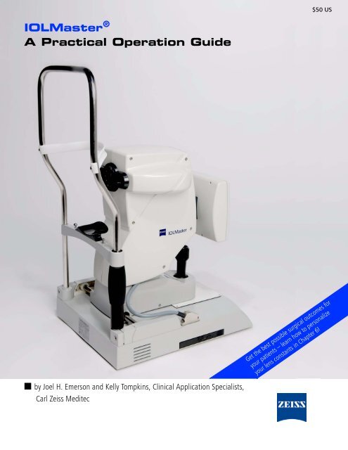
$50 US<strong>IOLMaster</strong> ®A <strong>Practical</strong> <strong>Operation</strong> <strong>Guide</strong>Get the best possible surgical outcomes foryour patients – learn how to personalizeyour lens constants in Chapter 6!■ by Joel H. Emerson and Kelly Tompkins, Clinical Application Specialists,<strong>Carl</strong> <strong>Zeiss</strong> Meditec
iiDRAFT/PRE-RELEASE/CONFIDENTIAL4/23/07Part Numberand RevisionMCAFNumber<strong>IOLMaster</strong> ® : A <strong>Practical</strong> <strong>Operation</strong> <strong>Guide</strong>Revision ControlBased onSoftwareVersion Description Release Date64365 Rev. A IOL.1411 5.01 <strong>IOLMaster</strong>: A <strong>Practical</strong> <strong>Operation</strong> <strong>Guide</strong> 2007.06Copyright© 2007 <strong>Carl</strong> <strong>Zeiss</strong> Meditec, Inc. All rights reserved.Trademarks<strong>IOLMaster</strong> is either a registered trademark or trademark of <strong>Carl</strong> <strong>Zeiss</strong> Meditec, Inc.in the United and/or other countries. All other trademarks used in this documentare the property of their respective owners.<strong>IOLMaster</strong>: A <strong>Practical</strong> <strong>Operation</strong> <strong>Guide</strong> PN 64365 Rev. A IOL.1411 2007.06
Contents iiiContentsDRAFT/PRE-RELEASE/CONFIDENTIAL4/23/07(1) The Eye and the <strong>IOLMaster</strong> .....................................................................................1-1•Eyes and Optics 101................................................................................................................ 1-1•How the Lenses of the Eye Work.............................................................................................1-2(2) Entering Surgeon Names and Lenses ................................................................... 2-1•Adding Surgeon Names ..........................................................................................................2-1•Choosing A Lens Modification Option ................................................................................... 2-3•Adding A Lens ....................................................................................................................... 2-5•Downloading and Importing Lenses...................................................................................... 2-7(3) Preparing Your Patient for Testing ....................................................................... 3-1•External Controls ....................................................................................................................3-1•Patient Preparation Tips ........................................................................................................ 3-2•New Patient Screen: Entering New Patient Information ........................................................ 3-3(4) Taking Measurements............................................................................................. 4-1•Part 1: Axial Length Measurement..........................................................................................4-1•Part 2: Corneal Curvature Mode ...........................................................................................4-14•Part 3: Anterior Chamber Measurement .............................................................................. 4-20•Part 4: White-to-White Measurement .................................................................................. 4-22•New with 5.01 software: <strong>IOLMaster</strong> Advanced Technology Plausibility Checks................... 4-24•Part 5: Calibration Check ..................................................................................................... 4-24•So … What Now?................................................................................................................ 4-25(5) Lens Calculations..................................................................................................... 5-1•Lens Calculation Mode ...........................................................................................................5-1•Choosing a Formula............................................................................................................... 5-4(6) Optimizing Lenses................................................................................................... 6-1•Preparing for Optimization .................................................................................................... 6-2•Lets Get Started!.................................................................................................................... 6-5•Optimizing the Haigis Formula .............................................................................................6-10•Now What? ...........................................................................................................................6-10(7) Data Management....................................................................................................7-1•Proper Shutdown....................................................................................................................7-1•Export or Transfer Data.......................................................................................................... 7-2•Holladay II Consultant ........................................................................................................... 7-4•Backing Up Surgeon and Lens Data....................................................................................... 7-4•Restore .................................................................................................................................. 7-5•Import.................................................................................................................................... 7-5•Finding All of This a Little Confusing?.................................................................................... 7-5(8) Frequently Asked Questions.................................................................................. 8-1<strong>IOLMaster</strong>: A <strong>Practical</strong> <strong>Operation</strong> <strong>Guide</strong> PN 64365 Rev. A IOL.1411 2007.06
ivIntroductionDRAFT/PRE-RELEASE/CONFIDENTIAL4/23/07Introduction“The eye is the light of the body; therefore if the eye is good, then the wholebody will be full of light, but if the eye is bad, then the whole body will be fullof darkness.”We are visual creatures. Our society, our technology, our entire way of life is centeredaround our ability to see. And if that ability is taken away from us, we will do everythingwe can to restore our sight.One of the most common causes of vision loss is the cataract – a clouding of the naturallens that sits behind the pupil. Exposure to certain chemicals and medications can causecataracts to develop. Ultraviolet light may speed up the process as well. Even poor healthis thought to play a part. But ultimately anyone who lives long enough will develop acataract, simply from the passing of time.The first known technique to restore vision lost from a cataract has been traced back toIndia, where, in the 5th Century B.C., the surgeon Susruta performed an operation whichlater came to be called “couching.” This technique involved literally pushing the cataractout of the way with a needle inserted into the eye. Though dangerous, couching wouldcontinue to be used as the primary form of treatment for cataracts for the next twothousand years.In the 1740’s, a French surgeon named Jacques Daviel performed the first known removalof the cataract from the eye – rather than simply pushing it aside like his predecessors – byphysically “popping” the clouded lens out through the pupil in one solid piece.While this new technique of cataract extraction was somewhat safer and more effectivethan couching, both operations left the patient severely far-sighted; distant objectsappeared blurry, and nearby objects looked even worse! The use of thick glasses wasrequired to provide the patient with usable vision after the operation.Then in the 1940’s, Harold Ridley successfully experimented with replacing the natural lenswith a synthetic one, in order to provide the patient with functional vision even withoutglasses after the cataract surgery.In the 1960's, Charles Kelman introduced the technique of phacoemulsification, in whichan ultrasonic probe is inserted into the eye, essentially liquefying the lens and suctioning itout through a tube.Ever since those early days, the surgical techniques and lens implant designs havecontinued to improve. Modern cataract surgery is typically performed as an outpatientprocedure, often with no stitches and only anesthetic drops to numb the eye. Lens implantsare now inserted in a rolled-up state and then unfold into their proper shape inside the eyeitself. While the patient may be at the surgical site for a few hours, the actual removal ofthe cataract and insertion of the lens implant often takes less than ten minutes.<strong>IOLMaster</strong>: A <strong>Practical</strong> <strong>Operation</strong> <strong>Guide</strong> PN 64365 Rev. A IOL.1411 2007.06
Introduction vDRAFT/PRE-RELEASE/CONFIDENTIAL4/23/07☞And yet, even with all of the advances in materials and techniques, there is alwaysa question of which implanted lens strength to use in order to give the patient thebest possible vision after surgery. For many years, we simply guessed at the implantpower needed, based on the patient’s glasses prescription. More recently, weutilized a combination of ultrasound A-scan devices and manual keratometry toolsand a simple algebraic equation to estimate the implant power needed. While suchmethods were innovative for their time – and certainly a vast improvement oversimply guessing – there is now available a much better way to acquire themeasurements needed and to correctly choose the best lens power: The <strong>IOLMaster</strong>.This innovative technology is easy to use, provides an unprecedented degree ofaccuracy, and has a number of automatic fail-safes to help prevent mistakes andoversights. In the hands of a skilled operator, the <strong>IOLMaster</strong> can measure andcalculate with such precision as to provide the absolute best lens power for eachpatient.The ability to see is one of the greatest gifts we have been given. And with the helpof this technology, you will be instrumental in restoring that gift to your cataractpatients. So it is our hope that this guide will assist you in your initial and ongoinguse of your new <strong>IOLMaster</strong> system.Note: This guide is based on Version 5.01 of <strong>IOLMaster</strong> system software.Special ThanksWe give special thanks to Mely Medel and Kathy Lewis for making this projectpossible, to John Gutierrez for his support in editing and layout, and as always, toour fellow Clinical Application Specialists for their support. We also thank thosewho reviewed the content of this guide and helped with editing, including DennyDugal and Claus Dreher for their technical expertise, and Katy Murphy for herclinical expertise. In addition, Joel offers particular thanks to Tom McMillan, whofirst introduced him to the <strong>IOLMaster</strong> many years ago.—Joel H. Emerson & Kelly TompkinsClinical Application Specialists,<strong>Carl</strong> <strong>Zeiss</strong> Meditec<strong>IOLMaster</strong>: A <strong>Practical</strong> <strong>Operation</strong> <strong>Guide</strong> PN 64365 Rev. A IOL.1411 2007.06
1-1The Eye and the <strong>IOLMaster</strong>(1) The Eye and the <strong>IOLMaster</strong>DRAFT/PRE-RELEASE/CONFIDENTIAL4/23/07CorneaLensRetinaWelcome to the first chapter of your <strong>IOLMaster</strong>’s practical operation guide. Soonenough, you will be reading about your new testing system and how to use it tomeasure your patients’ eyes. But before we discuss how to go about using the<strong>IOLMaster</strong>, it’s first important to understand what this system is testing—thehuman eye.So, in this chapter, we’ll discuss the various structures of the eye, how they assist infocusing light, and how cataracts and cataract surgery affect this ability to focuslight.Do you need to read this chapter in order to operate the <strong>IOLMaster</strong>? Well …technically, no, you don’t. You can follow the steps for testing the eye described inChapter (4), but I strongly advise against skipping ahead. The human eye is amarvelous and complex organ, and understanding how it interacts with light—both before and after cataract surgery—will give you a better perspective and amore intuitive grasp of the <strong>IOLMaster</strong>.Of course, if you are a doctor or a technician well-experienced in the anteriorsegment, what follows will undoubtedly be “old news” to you. But for those new tothe ophthalmic field in general, or the anterior segment (that is, the front half ofthe eye) in particular, I believe you will find this chapter very useful.Eyes and Optics 101For the purposes of explaining how the eye works, we’re going tosimplify the anatomy and mechanisms of the eye and say that the eye iscomprised of three main parts—the cornea, the crystalline lens, and theretina.The crystalline lens is a clear structure about the size and shape of anM&M ® , which sits just behind the dark pupil of the eye. Despite it’sname, this lens is not made of crystal, but is transparent living tissue. Itis made up of the nucleus which is the core of the lens, several corticallayers that surround the nucleus like the layers of an onion, and finallyan outer capsule or “bag” that holds everything in place. The crystalline lens helpsto focus images of light onto the retina, and can even change its shape in order toadjust this focus—or “accommodate”—when the various objects being viewedare at different distances from the eye.<strong>IOLMaster</strong>: A <strong>Practical</strong> <strong>Operation</strong> <strong>Guide</strong> PN 64365 Rev. A IOL.1411 2007.06
The Eye and the <strong>IOLMaster</strong> 1-2The cornea is the clear dome on the front of the eye. Like the crystalline lens, thecornea helps to focus images of light onto the retina. Though it does not changeshape like the crystalline lens, the cornea is the more powerful of the two,providing about two-thirds of the light-bending power of the eye.DRAFT/PRE-RELEASE/CONFIDENTIAL4/23/07The retina is the tissue at the back of the eye. The cornea and crystalline lenstogether focus images of light onto the retina, which then converts those imagesinto nerve impulses for the brain to interpret.How the Lenses of the Eye WorkLight reflects off an object and comes to the eyes asparallel rays of light. The outward-curving (or“convex”) clear dome of the cornea bends these raysof light inward into the eye. These converging rays oflight then pass through the crystalline lens of the eye,which bends them inward even more sharply.These rays cross over each other at a single spot calledthe “focal point”, and then begin to spread out ordiverge once again. When these diverging rays reachthe retina, an image of light is projected there, as if ona movie screen at the theater. Because the image appears beyond the focal point, itis flipped around backwards and upside down. But the brain expects this, andautomatically corrects the image’s orientation when it is processing the nerveimpulses it receives from the retina.CataractsThere are a number of patients who will come to youroffice under the impression that a cataract is a film orgrowth that forms over the cornea. It is a mythperpetuated by novels and movies in which blindcharacters have cloudy white corneas. While thecornea can certainly become cloudy over time, that isnot a cataract.A cataract is just another name for the crystalline lens;it is what the lens is called after one or more of itslayers have become clouded to the point that isaffecting the patient’s vision, or to the point that the doctor can clearly see it. A<strong>IOLMaster</strong>: A <strong>Practical</strong> <strong>Operation</strong> <strong>Guide</strong> PN 64365 Rev. A IOL.1411 2007.06
1-3The Eye and the <strong>IOLMaster</strong>cataractous lens does not focus images of light as well as a clear crystalline lenswould; by the time the images pass through the cataract, they may have becomeblurred or faded out. Conversely, some cataracts may also cause light to becomescattered as it passes through the lens, causing sources of light to seem overlybright, with distracting streaks and glare.DRAFT/PRE-RELEASE/CONFIDENTIAL4/23/07Cataract SurgeryWhen cataract surgery is performed, the cataract is not merely peeled off of thelens; remember, the cataract and the lens actually are the same thing. Instead thelens—which has become the cataract—is removed from the eye.The good news is that more light can get into the eye now, since the cataract hasbeen removed. The bad news is that without the crystalline lens, the eye is left withonly the cornea to focus images of light.Though the cornea is powerful, about twice aspowerful as the crystalline lens, typically it is still notpowerful enough by itself to focus images properlyonto the retina. Thus, if the cataract is removed andnothing more is done, the patient is left aphakic—literally “without a lens.” In most cases, aphakic eyesare farsighted; distant images are blurred, and nearbyimages are even worse. This is because the eye isshorter than the distance the cornea needs to focusthe image by itself.Placing a lens in front of the eye—either a thick lensin a pair of glasses, or a hard contact lens on thecorneal surface—can help an aphakic eye to focus theimage onto the retina.lens implantremaininglens capsuleSince the 1940's, though, there has been the option toimplant a small synthetic lens inside the eye itself,which provides the patient clear vision with minimalneed for glasses or contact lenses. Over the past sixdecades, techniques and technologies have improvedcontinuously, yielding safer surgeries and betterimplants.Today, in most cases, the front of the crystalline lenscapsule is removed, along with the clouded contents<strong>IOLMaster</strong>: A <strong>Practical</strong> <strong>Operation</strong> <strong>Guide</strong> PN 64365 Rev. A IOL.1411 2007.06
The Eye and the <strong>IOLMaster</strong> 1-4of the lens, leaving the rest of the clear capsule intact to hold the implanted lens inplace. Thus, the intraocular lens (or “IOL”) sits more or less in the same position thenatural lens once occupied.How Strong Should the Implant Be?DRAFT/PRE-RELEASE/CONFIDENTIAL4/23/07Now that we can implant a lens into the eye to replace the natural crystalline lensremoved during cataract surgery, the question arises as to how strong theimplanted lens should be. If it is too strong, the eye will be left nearsighted (onlyobjects near the eye come into focus), but if it is not strong enough, the eye will beleft farsighted (with distant objects blurred, and nearby objects even more blurred).In the past, surgeons simply had to guess at the implant strength, based on thepatient’s prescription for glasses or contacts. Then along came the notion ofmeasuring the length of the eye and the curvature of the cornea. How are thosetwo measurements useful for choosing a lens implant strength? Good question…By measuring the curvature of the cornea (these measurements are often called“K’s,” short for “keratometry”—literally, “corneal measurement”), we candetermine the focal distance of the cornea—that is, the distance from the corneato the image it’s projecting on the other side. The steeper the cornea is, the shorterthe distance is between the cornea and the image it is projecting. The flatter thecornea is, the longer the distance is between the cornea and the image it isprojecting.By measuring the length of the eye from the cornea to the retina (called the “axiallength”), we know what the focal distance should be to get the image projectedproperly on the retina.Typically once the crystalline lens is removed, the focal distance of the cornea islonger than the axial length of the eye. But by inserting a synthetic lens of theproper light-bending power, the overly-long focal distance can be shortened tomatch the actual length of the eye.<strong>IOLMaster</strong>: A <strong>Practical</strong> <strong>Operation</strong> <strong>Guide</strong> PN 64365 Rev. A IOL.1411 2007.06
1-5The Eye and the <strong>IOLMaster</strong>implantDRAFT/PRE-RELEASE/CONFIDENTIAL4/23/07axial lengthfocal distance shortenedSo, all the surgeon needs to do is insert a lens with enough light-bending power toshorten the focal distance to match the patient’s axial length. Easy, right?Well… as it turns out, it’s not as easy as that. Because the lens implant and thecornea have space between them, and because each one sits at different distancesfrom the retina, the equation becomes a bit more complex. That is why it isessential to obtain accurate measurements of both the axial length and the cornealcurvature.Before the invention of the <strong>IOLMaster</strong>, analysis of ultrasonic echoes (i.e., an“A-scan”) was used to measure the axial length; and lining up and focusing imagesreflected off the cornea (i.e., “manual keratometry”) was used to measure cornealcurvature.But with ultrasound, it is difficult to tell whether the scan is directed toward themacula—that is, toward the area of the retina that provides the patient withcentral vision. What’s more, contact ultrasound requires actually touching thecornea with a probe, which presses the cornea in and artificially shortens the axiallength. The alternative to contact ultrasound was immersion ultrasound. While thismethod certainly is more accurate than contact ultrasound, it requires the patient’slids to be held open while a plastic tube is placed over the eye and filled withsaline. Not only is this uncomfortable for the patient, it still fails to provide certaintythat the scan is being directed to the patient’s central vision.As for manual keratometry, this technique was designed for measuring theperipheral cornea for contact lens fittings. Peripheral corneal measurements do notnecessarily provide the correct central corneal curvature—the curvature that mostdirectly impacts the patient’s vision. What’s more, the measurement requires<strong>IOLMaster</strong>: A <strong>Practical</strong> <strong>Operation</strong> <strong>Guide</strong> PN 64365 Rev. A IOL.1411 2007.06
The Eye and the <strong>IOLMaster</strong> 1-6looking through a scope and turning various knobs to carefully align a series ofshapes reflected from the patient’s cornea. The accuracy of these measurementsdepends greatly on the examiner’s skill, patience, and (ironically) his or her ownclarity of vision.DRAFT/PRE-RELEASE/CONFIDENTIAL4/23/07Now we have the <strong>IOLMaster</strong>. It is quick, easy to use, and highly accurate. Itmeasures the axial length along the eye’s visual axis directly to the macula. Itmeasures more centralized—and thus more relevant—corneal curvature. Itsmeasurements are highly consistent and repeatable. And it has a number of built-insafety checks to help catch any mistakes the tester may make.Now for what you’ve been waiting for…using the <strong>IOLMaster</strong>. Chapter (2) will dealwith setting up your database of doctors and lenses, and Chapters (3) through (5)will deal with testing and calculating results.<strong>IOLMaster</strong>: A <strong>Practical</strong> <strong>Operation</strong> <strong>Guide</strong> PN 64365 Rev. A IOL.1411 2007.06
2-1Entering Surgeon Names and Lenses(2) Entering Surgeon Names and LensesDRAFT/PRE-RELEASE/CONFIDENTIAL4/23/07Okay, so you have an <strong>IOLMaster</strong> and are probably anxious to get started takingmeasurements. That time will come soon enough. Before taking anymeasurements, it is a good idea to set up the user database first. This chapter dealswith that very subject.Adding Surgeon Names1. From the NEW PATIENT screen, select User Database from the Options menu(click Options > User Database). A dialog titled Please enter passwordappears.2.Click the down-arrow by the Name field and select Administrator, as shown.3.Leave the password blank, and click OK. The User Database dialog appears,showing the tab for the user you selected (Administrator).<strong>IOLMaster</strong>: A <strong>Practical</strong> <strong>Operation</strong> <strong>Guide</strong> PN 64365 Rev. A IOL.1411 2007.06
Entering Surgeon Names and Lenses 2-2A list of surgeons (if you have entered any) appears on the left. To add a newsurgeon to the list, just type his or her name exactly as you want it to appearon your lens calculation printouts in the Name field at right and click Add.DRAFT/PRE-RELEASE/CONFIDENTIAL4/23/07☞Important note: At this stage, you may choose to assign a password to youradministrator or your physician. Using passwords has pros and cons;ultimately, it is the physician's decision whether or not to use them. If you doassign a password to the administrator, be very careful not to forget it. If youforget the administrator's password, it is not an easy fix and will require aphone call to <strong>Carl</strong> <strong>Zeiss</strong> Meditec technical support.As you add new surgeons, their names will be listed alphabetically and eachwill one will have his or her own tab at the top of the screen. The tabs alsoappear alphabetically (except that the Administrator tab will always be at thefar left).4.After you have added a surgeon or surgeons (or if they’re already there frombefore), click on their tab at the top of the screen.You are now in that surgeon’s personal lens file. A list of already entered lensesappears on the left, and a lot of empty fields on the right, unless one of thelenses is highlighted, as shown below.These boxes arefor the modifiedlens constantsfor the variousformulas you willbe using.The fields to the right are empty when no lens is selected. In that case, they arefor entering new lens data. These fields are highlighted above.<strong>IOLMaster</strong>: A <strong>Practical</strong> <strong>Operation</strong> <strong>Guide</strong> PN 64365 Rev. A IOL.1411 2007.06
2-3Entering Surgeon Names and LensesSo, now you are in the surgeon files and are ready to add a lens. At this point, youwill have to decide what lens constant information you will be inputting for eachnew lens.Choosing A Lens Modification OptionDRAFT/PRE-RELEASE/CONFIDENTIAL4/23/07☞Each lens comes with a manufacturer’s A-constant, a number which can be used invarious lens calculation formulas. But traditionally, this A-constant has beencalculated assuming the use of contact ultrasound A-scans and manual cornealcurvature measurements. Because the <strong>IOLMaster</strong> obtains measurements differentlythan the lens manufacturer’s A-constant is designed for, modifications to thisnumber need to be made. Typically, the <strong>IOLMaster</strong> measures the axial lengthmeasurement longer than contact ultrasound. The reason for this is that withcontact ultrasound you are compressing the cornea, thereby shortening the axiallength of the eye, but with the <strong>IOLMaster</strong> there is no contact with the eye and noartificial shortening of the axial length. This difference, if ignored, can result inundesired post-operative refractions.Important note: If you are using immersion ultrasound for your axial lengthmeasurement method and have a lens constant that has already beenadjusted for immersion measurements, there is a good chance that this lensconstant will also work well with the <strong>IOLMaster</strong>. You can proceed to theAdding A Lens section on page 2-5 and input these numbers into the<strong>IOLMaster</strong> lens database.Below are a few of the most common options you have for modifying your lensconstants. The surgeon should decide which method to use.1. Input lens constant information from the ULIB website. The ULIB websitecontains optimized lens constant information for many lenses, provided bymany surgeons all over the world. The ULIB website is maintained by Dr.Wolfgan Haigis, PhD. You can find this website by doing an internet search for“ULIB,” or by following the link in the <strong>IOLMaster</strong> page on the <strong>Carl</strong> <strong>Zeiss</strong>Meditec website, which can be found at www.meditec.zeiss.com/iolmaster.You can then choose either to print out this list of optimized lens constants andmanually enter the information into the <strong>IOLMaster</strong>, or download theinformation electronically to a CD or USB memory stick and import it directlyinto the <strong>IOLMaster</strong>. (For instructions, see the Downloading and ImportingLenses section on page 2-7.)This method has proven very useful for many surgeons and is probably themost commonly used method. However, every surgeon’s technique is different<strong>IOLMaster</strong>: A <strong>Practical</strong> <strong>Operation</strong> <strong>Guide</strong> PN 64365 Rev. A IOL.1411 2007.06
Entering Surgeon Names and Lenses 2-4– the A-constants that work for one doctor may not necessarily work foranother.DRAFT/PRE-RELEASE/CONFIDENTIAL4/23/07☞You may notice that not every IOL in existence appears on the ULIB list. Onlylenses used often enough by the ULIB group to have sufficient data for lensconstant optimization make it onto the site. Below is an example of what thelist of lenses on the ULIB website looks like.As you can see there is a lens constant/surgeon factor for each formula that isused on the <strong>IOLMaster</strong> Please note that the nominal value is the manufacturer’slens constant.You can check Dr. Warren Hill’s website (www.doctor-hill.com) for some additionaloptimized lens constants. He has some of these posted for you to getstarted, including some A/C IOL constants.Important note: Specific A-constants found on the ULIB website and Dr. Hill’swebsite are not recommended by <strong>Carl</strong> <strong>Zeiss</strong> Meditec. You must examine themand determine if they are right for you.2.Side by Side comparison study. Measure the axial length on the <strong>IOLMaster</strong>.Then measure the axial length with contact ultrasound A-scan. You shouldmeasure 10 to 20 patients. Subtract the ultrasound’s average axial length fromthe <strong>IOLMaster</strong>’s average axial length. This will produce a very small number,probably around 0.10 or 0.15. Whatever this small number is, multiply it by 3.Then add this new number to your manufacturer’s A-constant.Example:Avg axial length on <strong>IOLMaster</strong> = 23.70 mmAvg axial length on contact ultrasound = 23.60 mm23.70 – 23.60 = 0.100.10 x 3 = 0.30<strong>IOLMaster</strong>: A <strong>Practical</strong> <strong>Operation</strong> <strong>Guide</strong> PN 64365 Rev. A IOL.1411 2007.06
2-5Entering Surgeon Names and LensesThis is the number you will add to any manufacturer’s A-constant. Now thatyou have this number, proceed to the Adding A Lens section on page 2-5.DRAFT/PRE-RELEASE/CONFIDENTIAL4/23/07This method is more customized and takes into account your own practice“compression factor”.3.Speak to your lens representative, explain that you have an <strong>IOLMaster</strong>, and askwhat numbers you should use. Often lens manufacturers will have arecommended lens constant for use with the <strong>IOLMaster</strong>. Write this informationdown, and proceed to the Adding A Lens section on page 2-5.Ultimately, whichever method you use, you are strongly encouraged to:1. Do a comparison of your old method of measuring and calculating IOL powerand the new method using the <strong>IOLMaster</strong>. Do not rely solely on calculationsfrom the <strong>IOLMaster</strong> until you feel comfortable with the expected outcomesusing the <strong>IOLMaster</strong>.2.Perform an optimization of the lens constants, once you have enoughpost-operative data to do so. Chapter (6) deals with the optimization programon the <strong>IOLMaster</strong>.Adding A LensNow that you have your lens constants, it’s time to enter them into the <strong>IOLMaster</strong>.You will need to be in one of the surgeon’s files for this.1. First, type the name of the lens in the lens Name field at upper right.<strong>IOLMaster</strong>: A <strong>Practical</strong> <strong>Operation</strong> <strong>Guide</strong> PN 64365 Rev. A IOL.1411 2007.06
Entering Surgeon Names and Lenses 2-62.Then type the appropriate number in the Manufacturer A-constant field (calledA const.: ____ Manufact, located just below the lens name box). This numberis based on the method of lens constant modification you have chosen.DRAFT/PRE-RELEASE/CONFIDENTIAL4/23/073.Next, enter the appropriate lens constant numbers in the fields next to eachformula. These numbers are based on the method of lens constantmodification you have chosen.• For option 1, using the ULIB website lens constant information: You can enterthe information manually in each field from a printout, or import it directly intothe <strong>IOLMaster</strong> from the media you have downloaded it to. When entering datamanually, make sure you enter each number correctly in the field thatcorresponds to its formula. Remember the nominal number is what you put inthe manufacturer’s box; you do not need to enter a manufacturer’s ACD. Toimport data directly, see the Downloading and Importing Lenses sectionon page 2-7.• For option 2, side by side comparison: Just add whatever your result was—continuing the example above, you would add 0.3—to whatever A-constant isprinted on the lens box. Enter the resulting sum in the Manufact. field. Select½ D or ¼ D (diopter) steps, and click Add. The instrument will automaticallycalculate and fill in the rest of the formula fields below. It is a good idea to goback and change the manufacturer’s number to the correct manufacturer’slens constant and then click Set. This way, you will know at a glance whetherthe lens constant information was adjusted.<strong>IOLMaster</strong>: A <strong>Practical</strong> <strong>Operation</strong> <strong>Guide</strong> PN 64365 Rev. A IOL.1411 2007.06
2-7Entering Surgeon Names and Lenses• For option 3, getting the information from the lens representative: Enter theinformation you are given in each field, including the fields for each formula.Select ½ D or ¼ D (diopter) steps, and click Add.DRAFT/PRE-RELEASE/CONFIDENTIAL4/23/07☞Important note: Adding a new lens to one surgeon’s file will not add it toevery surgeon’s file. You must add each surgeon’s desired lenses under his orher own tab.Congratulations! You’ve just added a lens! This lens will now be available to beplaced in one of the lens fields in the LENS CALCULATION screen.Downloading and Importing LensesDownloading ULIB Lens Constant Data onto a CD-RW or Jump DriveYou will need to use another computer (not the <strong>IOLMaster</strong>) that is connected to theinternet to access the User Group for Laser Interference Biometry (ULIB) website.This computer will need to have a CD burner or a free USB port with a compatiblejump drive (also called thumb drives, memory sticks, USB sticks, etc.).1. Put a blank CD-RW into the CD drive, or plug in your USB memory stick, so thatthe computer is ready and recognizes the drive.2.Go the ULIB website:www.augenklinik.uni-wuerzburg.de/eulib/index.htmLinks to it can be found on the <strong>IOLMaster</strong> page of the <strong>Carl</strong> <strong>Zeiss</strong> Meditec website(www.meditec.zeiss.com/iolmaster) and through Dr. Warren Hill’s website(www.doctor-hill.com).3.Near the bottom of the ULIB webpage, click the link to Download optimizedIOL constants for the <strong>Zeiss</strong> <strong>IOLMaster</strong>.4.On the next webpage that appears, explanatory paragraphs at the topconclude with the following sentence: “To proceed with the download, clickhere for the English version”. Click where indicated—on the highlighted word“here”—and you will be taken to a <strong>Zeiss</strong> disclaimer page.5.Read the page. At the bottom, select the checkbox next to “Yes, I’ve read theinstructions for using the constants.” When you do, a Start download optionwill appear. Click Start download.6.At this point, the instructions may vary depending on your browser. ForInternet Explorer, select the Save option. A dialog will prompt you to specifywhere to save the file. In the Save in: field, use the down-arrow to locate your<strong>IOLMaster</strong>: A <strong>Practical</strong> <strong>Operation</strong> <strong>Guide</strong> PN 64365 Rev. A IOL.1411 2007.06
Entering Surgeon Names and Lenses 2-8CD burner (probably the “D:” drive) or the jump drive you have plugged into afree USB port (probably the drive with the highest letter – maybe “E:” or “F:” or“G:”). Click Save.DRAFT/PRE-RELEASE/CONFIDENTIAL4/23/07If you are using a jump drive, the file will probably be downloaded directly intothe jump drive. If you are using a CD burner – depending on the program yourcomputer uses – the download may save the file directly onto the CD, or it maycopy it into a temporary file first. If the latter situation obtains, a message willprobably pop up on your screen saying something like “You have files waitingto be copied onto CD. Click here to begin.” Complete the copying process ontoyour CD.Importing Files from the CD or Jump Drive into the <strong>IOLMaster</strong>Now you have a CD or a jump drive with a whole list of lenses that can bedownload into your <strong>IOLMaster</strong>. Make sure you’ve entered all the surgeons on theAdministrator tab before proceeding.1. You will want to be back in the Administrator tab for this. If you are already inthe Surgeon / Lens files, just click on the Administrator tab (far left) to return toit. If you are back in the NEW PATIENT screen, click Options > User Database,select Administrator in the Name field and click OK to get back to theAdministrator tab.2.Install the CD into its drive (on the left side of the system’s base when facingthe screen) or the jump drive into its port (on the right side of the base). Givethe computer a few seconds to recognize the CD or jump drive.3.On the Administrator tab, click Import.ClickImport<strong>IOLMaster</strong>: A <strong>Practical</strong> <strong>Operation</strong> <strong>Guide</strong> PN 64365 Rev. A IOL.1411 2007.06
2-9Entering Surgeon Names and LensesThe import dialog that appears has a list of lenses on the left and doctors onthe right.DRAFT/PRE-RELEASE/CONFIDENTIAL4/23/074.Select the desired lenses by clicking on them. To choose more than one lens ata time, hold the Ctrl key while clicking every lens you want to import.5.Select one or more doctors for whom you will import the selected lenses. Holdthe Ctrl key while clicking to select multiple doctors. If each surgeon in yourpractice uses different lenses you will complete this process separately for eachone.6.Click the >> button to import the highlighted lenses into the lens database forthe selected doctor(s).You may notice that not every IOL in existence appears on the list you downloaded.Recall that only lenses used often enough by the ULIB group to have sufficient datafor lens constant optimization make it onto the site.☞A very important note: If you have already optimized a certain lens, then youdo NOT want to import that lens to your lens database on the <strong>IOLMaster</strong>. Ifyou do, it will erase your optimized lens numbers and replace it with thewebsite’s numbers.<strong>IOLMaster</strong>: A <strong>Practical</strong> <strong>Operation</strong> <strong>Guide</strong> PN 64365 Rev. A IOL.1411 2007.06
Preparing Your Patient for Testing 3-1(3) Preparing Your Patient for TestingDRAFT/PRE-RELEASE/CONFIDENTIAL4/23/07Now that we’ve covered the basics of what you will be testing and you have set upyour user database, we are ready talk about how you will perform testing. Thepurpose of this chapter is to cover patient preparation and entering new patientdata. The next chapter will cover actual measuring of axial length, cornealcurvature, anterior depth, and white-to-white.External ControlsJoystickOn/Off switch(on side)Table heightcontrolWhile most of the external controls (the up/down button of the table, the knob toraise and lower the chinrest, etc.) will be familiar to most operators, there are a fewdetails that warrant further explanation.The “mouse” touchpad and buttons. At the bottom of the keyboard is a touchpadwith left and right “mouse” buttons. If you have a laptop computer, you’veprobably used these before. But if not, here’s how they work:☞You can move your arrow-cursor around on the screen by putting your finger on thetouchpad and then sliding your finger in the desired direction. When the cursor isover what you want to select, push the left “mouse” button (or you can sharply tapthe pad with your finger, which sends the same signal to the computer as a click).A press of the left “mouse” button or tap on the touchpad is what we mean whenwe say “click” in this guide. (Right-click means to press the right “mouse” button.)Note: You will always be using the left mouse button.Try to avoid moving the cursor with short strokes on the touchpad. Instead, placeyour finger on the touchpad and move the cursor using long strokes. This is<strong>IOLMaster</strong>: A <strong>Practical</strong> <strong>Operation</strong> <strong>Guide</strong> PN 64365 Rev. A IOL.1411 2007.06
3-2Preparing Your Patient for Testingbecause short, quick strokes can lead to unintentional “clicks” as you pick up andput down your finger repeatedly. So, until you are used to the pad, you mayactivate the wrong icon by mistake by using quick finger strokes on the pad, oreven letting your wrist bump into it while you are typing.DRAFT/PRE-RELEASE/CONFIDENTIAL4/23/07If, after some practice, you find you can’t get used to moving the cursor with thetouchpad, you can use a regular mouse instead. Just follow the keyboard cordalong to where it plugs into the <strong>IOLMaster</strong>. There the cord splits into two plugs – apurple one for the keys and a green one for the mouse. Pull out the green plug andplug your mouse cord in instead. You’ll want to use a “normal” mouse (i.e. not thewireless or laser-operated variety) that has a PS2 plug.The joystick. You can raise or lower the <strong>IOLMaster</strong> scanning device by rotating thejoystick knob. Rotating/twisting clockwise will raise the device upward, toward thepatient’s forehead, while rotating/twisting counterclockwise will lower the devicetoward the patient’s cheek. You can also move the scanning device right and left,and forward and back, by moving the joystick in the same direction as you want togo. You will have better control over the scanner’s movements if you use twohands.Patient Preparation TipsBefore you even begin testing your patient with the <strong>IOLMaster</strong>, there are somepreparations you can make to increase the precision and accuracy of your testing:• Ensure corneal stability: Modern cataract surgery is not simply the removal of aclouded lens, it is refractive surgery. Patients expect good vision after surgery,without having to use glasses or contact lenses. One of the things that caninterfere with good post-operative vision are pre-operative measurementsmade on an unstable cornea. Contact lenses warp corneas, sometimes just alittle, sometimes a lot. If a patient wears contact lenses, make sure he or sheleaves them out long enough for the cornea to return to a normal, stable shapebefore measuring. The use of refractions and topographies may be needed toensure the cornea has ceased to change.• Don’t touch the cornea: Schedule your <strong>IOLMaster</strong> testing in such a way thatthe patient’s eye has not been touched that day – such as from ultrasoundA-scans, automounter pressure checks, gonioscopies, etc. Any and all of thesetests can disrupt the tear film and corneal shape, thus throwing offmeasurements.<strong>IOLMaster</strong>: A <strong>Practical</strong> <strong>Operation</strong> <strong>Guide</strong> PN 64365 Rev. A IOL.1411 2007.06
Preparing Your Patient for Testing 3-3New Patient Screen: Entering New Patient InformationDRAFT/PRE-RELEASE/CONFIDENTIAL4/23/07The first screen that appears when you turn the instrument on is a reminder that adaily calibration check of the <strong>IOLMaster</strong> is very important. (See Chapter (7) forinstructions to perform a calibration check.) Click the OK button to move to thenext screen, which is the NEW PATIENT screen. When you are in any of the testingscreens, and you want to get back to the NEW PATIENT screen, just move your cursorand click on the New Patient icon, shown at left.There are four important things you can do on the NEW PATIENT screen: add a newpatient to test, select an existing patient to test, recall old test results, and deleteunwanted files.list ofexistingpatientsAdding a new patient to testfields toenter newpatientinformationMake sure your blinking cursor bar is in the Last Name field at the upper right ofthe screen. If it’s not, move your cursor there and click on the field. Now you canbegin to enter the patient’s data. Use the Tab or Enter key to move between fields.You always must enter data for last name, first name, and date of birth; ID numbermay also be required, depending on the system settings. You can enter moreinformation if you wish to, or simply begin testing.If some fields contain information you don’t want to be there (such as from the lastpatient you tested, or from accidentally having clicked on an existing patient’sname in the list), click on the word <strong>IOLMaster</strong> at the top of the patient list. Thiswill clear all the fields to give you a fresh start.Click New at the bottom to begin testing. (The New button does not mean “newpatient” in this context; instead, it means “new test.”)<strong>IOLMaster</strong>: A <strong>Practical</strong> <strong>Operation</strong> <strong>Guide</strong> PN 64365 Rev. A IOL.1411 2007.06
3-4Preparing Your Patient for TestingSelecting an existing patient to test againIf you want to re-test a patient who is already in the patient list, click the patient’sname and then click New, or just double-click the name, and the test begins.Recalling old test resultsDRAFT/PRE-RELEASE/CONFIDENTIAL4/23/07✪☞To find and view a specific test result for a certain patient, click the “+” to the leftof the patient’s name and their test dates will appear. To view a result, click tohighlight the date you want and click Open, or just double-click on the date.Helpful hint: When trying to recall old tests, avoid double-clicking on a patient’sname, or selecting a name and then clicking New. Instead of opening old testresults, these actions will begin a new test and result in a new test date in thepatient’s list of tests.Deleting unwanted filesIf you want to delete an entire patient, click on a patient’s name in the list andpress the Delete key on the keyboard. You will have to confirm the deletion byclicking Yes.If you just want to delete a particular visit, click the “+” by the patient’s name, clickon the date you want to delete, then press Delete on the keyboard. Click Yes toconfirm your action.Note: If you delete the only date listed for a patient, then all data for thatpatient is deleted too.<strong>IOLMaster</strong>: A <strong>Practical</strong> <strong>Operation</strong> <strong>Guide</strong> PN 64365 Rev. A IOL.1411 2007.06
Taking Measurements 4-1(4) Taking MeasurementsAt this point you are probably anxious to get to the fun stuff, taking measurements!This chapter is broken into five parts.• Part 1: Axial Length Measurement, below• Part 2: Corneal Curvature Mode, page 4-14• Part 3: Anterior Chamber Measurement, page 4-20• Part 4: White-to-White Measurement, page 4-22• Part 5: Calibration Check, page 4-24DRAFT/PRE-RELEASE/CONFIDENTIAL4/23/07☞If you are reading this chapter, it is assumed you are already familiar with theinformation provided in the previous chapters. You will also notice that in thischapter we include sections called “Best Practices.” These are included to highlightwhat we consider the best ways to use the <strong>IOLMaster</strong>. We hope this is helpful.Important note: As you learn about taking measurements as explained in thischapter, it is important that you practice these techniques on a fellowtechnician – not on an actual patient who will have cataract surgery. Youmust be proficient with these measurement techniques before performingthem on patients. It is also extremely important that you check thecalibration of your <strong>IOLMaster</strong> every day before takingmeasurements on actual patients. Please see Part 5: CalibrationCheck (page 4-22) for detailed instructions to check the calibration.Part 1: Axial Length MeasurementHow Does It Work?See illustration below for a detailed description. Basically, the <strong>IOLMaster</strong> uses lightto measure the axial length of the eye, the distance from the front surface of thecornea to the retina; whereas A-scan ultrasound uses sound waves to measure thisdistance.<strong>IOLMaster</strong>: A <strong>Practical</strong> <strong>Operation</strong> <strong>Guide</strong> PN 64365 Rev. A IOL.1411 2007.06
4-2Taking MeasurementsDRAFT/PRE-RELEASE/CONFIDENTIAL4/23/07☞Important Note: Unlike A-scan ultrasound, which reflects off the wide cuppedsurface of the macula, the <strong>IOLMaster</strong> beam passes through the translucentsurface of the retina and back further to the more opaque pigment layer. Thecomputer corrects for this difference.In addition, the use of contact ultrasound will indent the cornea, thusdecreasing the distance between the cornea and the retina and artificially<strong>IOLMaster</strong>: A <strong>Practical</strong> <strong>Operation</strong> <strong>Guide</strong> PN 64365 Rev. A IOL.1411 2007.06
Taking Measurements 4-3shortening the axial length measured. Because of this, axial lengthsmeasured on the <strong>IOLMaster</strong> are almost always longer than those obtainedthrough contact ultrasound.How to Perform the TestDRAFT/PRE-RELEASE/CONFIDENTIAL4/23/07right eye (OD)data columnOnce you click the New button back on the NEW PATIENT screen, your screenchanges into testing mode. A video image of the eye appears in the middle of thescreen and a row of icons appears along the bottom. Empty columns (soon to befilled with data) appear to the left and right of the video image.left eye (OS)data columnHave the patient come forward into the chinrest. Get the eye lined up with the redmarker, and make the patient comfortable by raising or lowering the table. Thepatient can hold onto the handle bars at either side of the <strong>IOLMaster</strong>, if needed.The instrument knows which eye you are testing by which side the scanner ismoved to. When you have the scanner in front of the patient’s right eye, data willappear to the left of the video image. When you have the scanner in front of thepatient’s left eye, data will appear to the right of the video image.Tell your patient to always stare straight ahead at the spot of light. The spot willchange color, depending on which part of the test you are performing, but it willalways be straight ahead. Allow the patient to blink normally. Tell the patient youwill inform them when they need to stop blinking.<strong>IOLMaster</strong>: A <strong>Practical</strong> <strong>Operation</strong> <strong>Guide</strong> PN 64365 Rev. A IOL.1411 2007.06
4-4Taking MeasurementsWhen you first come to this screen – or when you’ve just switched from one eye tothe other – you’ll notice that the magnifying glass icon at lower left has beenselected automatically. This indicates you are in Overview Mode.Overview ModeDRAFT/PRE-RELEASE/CONFIDENTIAL4/23/07✪This is the first screen that appears when you click New to begin testing. If you areon a different testing screen, and wish to return to Overview Mode, just move yourcursor over the Overview icon and click. Alternatively, you can press the letter “O”on the keyboard.Note that the Overview Mode is NOT a test. It is just your chance to get lined upwith the patient’s eye. So you do not have to spend much time here at all…close isgood enough.1.First, move the scanner left and right as needed, androtate the joystick to move the scanner up and down asneeded, to get the green cross-hairs over the dark pupil ofthe eye.2.Next, move the scanner forward toward the patient orpull it back away from the patient as needed to focus theimage of the eye. You will know when you are in focusbecause the little spots of light reflecting in the pupil willbecome very small and sharp. But remember, this is NOT atest, so don’t stress about whether or not the spots areperfectly focused…you’re going to have to re-focusanyway in a few seconds.Helpful hint on focusing: If you are moving toward the patient and the lights aregetting smaller and sharper, then you’re on the right track. But if you are movingtoward the patient and the lights are getting larger and fuzzier, then you have gonetoo far – start pulling back toward you until the spots of light get smaller again. Forpractice, feel free to “overshoot” – that is, keep going forward and the lights willstart to get larger and fuzzier because you’ve gone too far in that direction. Thisway, you will learn how small the lights are supposed to get, and you’ll know whatit looks like when you’re in focus.3.Finally, without moving the joystick, push the button on top of the joystick. Thiswill advance you to the next part of the test.Axial Length ModeThis is the “A-scan” test, but performed with lasers instead of ultrasound. The testmoves into this mode when you push the joystick button at the end of the Overview<strong>IOLMaster</strong>: A <strong>Practical</strong> <strong>Operation</strong> <strong>Guide</strong> PN 64365 Rev. A IOL.1411 2007.06
Taking Measurements 4-5Mode. However, if you are on a different screen, and wish to return to Axial LengthMode, just move your cursor over the Axial Length icon and click. Alternatively, youcan press the letter “A” on your keyboard.DRAFT/PRE-RELEASE/CONFIDENTIAL4/23/07In Axial Length Mode, the eye zooms in very close, so the pupil fills most of thescreen. If you ever “get lost” and cannot find the center of the pupil, just return toOverview Mode by clicking on the magnifying glass icon, or by pressing the “O” keyon the keyboard.1.First, get your spot of light somewhere within the greencircle. If you’ve entered this mode directly from OverviewMode, your spot of light will probably already be in thecircle. Otherwise, move the scanner left and right asneeded, and rotate the joystick to move the scanner up anddown as needed, to get the spot of light within the greencircle.The spot of light just needs to be somewhere – anywhere –within the green circle. It does not need to be “dead center.”Sometimes, in fact, intentionally moving the spotaround within the circle will help you to scan around adense area of the cataract.2.Next, you’ll want to focus the spot of light. Again, if you’ve just come herefrom Overview Mode, chances are the spot will be fairly small and sharpalready. But if not, move the scanner forward toward the patient or pull it backaway from the patient as needed to focus the image on the eye. You’ll knowyou are in focus when the little spot of light on the pupil becomes very smalland sharp.Sometimes it’s hard to tell if the spot is really as small and sharp as it can be.But you can double-check your focus by looking at the vertical line of light thatextends up and down from the central spot. If this line is thin and sharp, thenyou’re in focus!3.Now, say to the patient: “Blink a couple times…now stop blinking and lookstraight ahead at the light.” Push the joystick button. The screen flashes for asecond, and then a number appears in the left or right eye data column. (Ifyou’re testing the right eye, the number appears on the left, and vice versa.)This number is the axial length (or “AL” for short), which is the length of theeye – the distance from the cornea to the retina – measured in millimeters(mm).<strong>IOLMaster</strong>: A <strong>Practical</strong> <strong>Operation</strong> <strong>Guide</strong> PN 64365 Rev. A IOL.1411 2007.06
4-6Taking MeasurementsDRAFT/PRE-RELEASE/CONFIDENTIAL4/23/07✐Best practice: The <strong>IOLMaster</strong> requires you to take at least 5 measurements. It is agood idea to take these five measurements with the white light in differentquadrants of the green circle. Take the first one in the center, and then for eachsuccessive measurement, rotate the joystick to move the white light and take ameasurement in each of the four quadrants of the green circle. We also recommendthat you take two more measurements: one after you pull the joystick back anddefocus the light to the size of the green circle; and a second after you push thejoystick in towards the patient again This will give you a total of 7 measurements.The reason for taking measurements in this way is to try to “get around” some ofthe denser opacities of a patient’s cataract. The image below shows how cataractshave varying opacity in different areas of the lens, and you may find that you get abetter signal in areas where the cataract isn’t as dense.4.Evaluate your results. You can evaluate the quality of your scans in two ways:First, by evaluating the waveform graph itself, and second, by the SNR value.Evaluating the Waveform GraphThe waveform graph is the red, spiky line superimposed on the video image aftereach push of the button. A good graph should have one tall spike ending in aclearly defined single peak, like the one shown below next to the Chrysler Building.There will be a row of smaller spikes appearing on either side of the primary central<strong>IOLMaster</strong>: A <strong>Practical</strong> <strong>Operation</strong> <strong>Guide</strong> PN 64365 Rev. A IOL.1411 2007.06
Taking Measurements 4-7spike, with each of the smaller spikes becoming shorter and shorter until theybecome a flat line of “background static”.DRAFT/PRE-RELEASE/CONFIDENTIAL4/23/07Chrysler Building,New York City= IdealSears Tower,waveformChicagoA double peak, like that shown next to the Sears Tower, is not considered a goodgraph. Because there are two peaks, the instrument isn’t sure where to place themeasurement cursor, and this can result in erroneous measurements. A little laterwe’ll tell you what to do when you get a double peak.The more interference with a scan – usually from dense cataracts – the higher andshakier the “background static” line will be. A blink or eye movement will cause asection of the graph to “bottom out” to nothing. See below some examples of poorscans.=Doublepeakflatnoisewavesmovement<strong>IOLMaster</strong>: A <strong>Practical</strong> <strong>Operation</strong> <strong>Guide</strong> PN 64365 Rev. A IOL.1411 2007.06
4-8Taking MeasurementsWith scans like these, the word “error” will appear in the list of axial lengths,instead of a number. To delete such erroneous measurements, click to highlight theword “error” and press the Delete key.What to do with double peaksDRAFT/PRE-RELEASE/CONFIDENTIAL4/23/07Double peaks are caused when it is unclear which retinal layer is providing thebrightest reflection. Patients with a blond or otherwise pale fundus, or withmacular pathology, or who are fixating slightly off center, may have double peaksin their graphsFirst of all, if you suspect that you have a graph with a double peak, you can checkthis by zooming in on the graph. To zoom in, click the black “x-axis” line directlybelow the red spike. If you still can’t tell, zoom in further the same way: again clickthe black “x-axis” line directly below the red spike. Right-click to go back to theoriginal graph size.If there’s only one peak, and the graph looks typical, then use this as your “anchor”and delete all measurements that are not within 0.05 mm of this number.If there are two peaks, whichever peak is clearly the taller of the two willautomatically have the dot above it. If the dot is over the top of the right-handpeak, then you’re probably still okay. Just pick another graph or two. Try to find agraph that has just a single peak with a dot over it, and use that as your “anchor”to know which measurements to delete.If there are two peaks, and the dot is between the two peaks, or the dot is over theleft peak…then we have a problem. See the Best Practice section below for furtherinformation.✐If both peaks are of fairly equal height, then the computer will “split the difference”and put the dot between them.Best Practice: If you have a graph with two peaks, it is probably simplest and bestto delete the measurement that goes with the double-peak graph and take a fewmore measurements, trying to get more single peak graphs. However, for some<strong>IOLMaster</strong>: A <strong>Practical</strong> <strong>Operation</strong> <strong>Guide</strong> PN 64365 Rev. A IOL.1411 2007.06
Taking Measurements 4-9DRAFT/PRE-RELEASE/CONFIDENTIAL4/23/07✐patients – especially patients with blond or pale retina or with macular pathologies– most of your graphs may end up having double peaks. If you were to delete alldouble peaks, then you would not have enough “good” measurements left! Soagain, the right-hand peak is usually the correct one. Just save all themeasurements that have a dot over the right-hand peak, and delete all themeasurements with a dot in between or over the left peak. Although it is possibleto move the measurement cursor to a different peak by holding down the leftmouse button and dragging it to a different peak, doing this will change the axiallength measurement. Therefore, we don’t recommend that you do this unless youare very experienced with this process. Please see the user manual for moredetailed information on how to do this.Double peaks from patients with an existing IOLWhen measuring a patient with a phakic IOL or a patient who is pseudophakicfrom previous cataract surgery, it is possible to get a double peak that can severelythrow off of the axial length measurement. The instrument will sometimes pick up areflection from the IOL, creating a false peak and making the axial lengtherroneously short.Best Practice: As shown in the image below, try to move around takingmeasurements in different quadrants and thereby avoiding reflections.This process is similar to trying to get around the denser portions of a cataract.Most importantly, use your own judgement: if you see an axial length measurement<strong>IOLMaster</strong>: A <strong>Practical</strong> <strong>Operation</strong> <strong>Guide</strong> PN 64365 Rev. A IOL.1411 2007.06
4-10Taking Measurementsabnormally short as in the case below, be aware that something like an existing IOLprobably is causing an erroneous measurement.New Composite GraphDRAFT/PRE-RELEASE/CONFIDENTIAL4/23/07This is a new feature introduced in version 5.01 software. After you have taken fiveaxial length measurements, a composite graph will appear in blue, with an SNRtraffic light. (See Signal-to-Noise Ratio or SNR on page 4-10 for anexplanation of this feature.) Underneath the original five measurements will appeara single composite value. Unlike previous versions, this composite value is not anaverage; <strong>IOLMaster</strong> calculates the composite value by combining the individualsignals, which significantly increases the signal to noise ratio.If individual axial lengths differ by more than 0.05 mm from their mean, themessage “multiple peaks” will appear. This does not mean the composite signal isunreliable, nor that the (composite) axial length is incorrect. However, in suchcases, we strongly recommend that you closely review the composite signal and theindividual axial lengths; as you review, adhere to the Best Practice describedunder What to do with double peaks, on page 4-8.Signal-to-Noise Ratio or SNRThe SNR, or Signal-to-Noise Ratio helps you evaluate how high your peak iscompared to the “background static” line. This number appears in the lower-rightcorner of the screen after each measurement. After five or more measurements, a“traffic light” appears along with the SNR value.If the SNR is too low (less than 1.6), a red “stop light” will appear above it and theword “error” will appear in the data column instead of a measurement.<strong>IOLMaster</strong>: A <strong>Practical</strong> <strong>Operation</strong> <strong>Guide</strong> PN 64365 Rev. A IOL.1411 2007.06
Taking Measurements 4-11If the SNR is of borderline quality (between 1.6 and 2.0, inclusive), a yellow“caution light” will appear above it and a numeric AL value will appear in the datacolumn, but it will have an exclamation mark (“!”) after it.DRAFT/PRE-RELEASE/CONFIDENTIAL4/23/07☞✐☞If the SNR is high enough (above 2.0), a green “go light” will appear above it and anumeric AL value will appear in the data column as normal.Important note: A high SNR does not necessarily mean you have a good scan.A blink, for instance, often produces a very high SNR because the distancebetween the highest peak and the “bottomed out” background static is quitea lot. Another possibility is having a great central spike height – and thus agood SNR – but retinal pathology causes the peak to be split in two,providing the wrong results. In short, the SNR is relevant only when taken inconjunction with the appearance of the graph.Best practice: After you have taken 5 measurements, if you don’t have a “greenlight” above the SNR value, you should take more measurements until you do havea “green light.”Important note: Because <strong>IOLMaster</strong> measures with a laser, the system willallow you to attempt the measurement up to twenty times. Even if you deletesome measurements, the system still will prevent you from acquiring morethan twenty measurements per eye each day.Some practices regularly take all twenty measurements instead of taking only therequired five. Once you have become practiced and efficient at obtaining axiallength measurements, it only takes a few more seconds to acquire all twentymeasurements, compared to the required five. This increases your likelihood ofobtaining a valid reading, and also improves your skills in obtaining good scans.As you are taking measurements, intentionally move the spot of light around in thegreen circle and take each measurement at a new location. Depending on the typeand density of the cataract, some areas may be easier to measure through thanothers. There are two ways to tell if one area of the green circle is better forscanning through than another: looking at the waveform graph shape, and lookingat the SNR number.Pictured at left are two simple patterns you could use to acquire multiplemeasurements through different locations. The first is a clockwise pattern startingat the top. The second is a zigzag pattern in which you slide to opposite sides ofthe circle. There is no right or wrong order – if you even have an order at all – buthaving one can help you remember which location works best for that eye.<strong>IOLMaster</strong>: A <strong>Practical</strong> <strong>Operation</strong> <strong>Guide</strong> PN 64365 Rev. A IOL.1411 2007.06
4-12Taking MeasurementsAs you measure through various sections of the circle, make a mental note of whichareas of the circle work best – that is, have both a “typical” graph and have ahigher SNR number. After your first ten measurements or so, you should knowwhere the “hotspot” is. Return to that spot, and finish taking your twentymeasurements there.DRAFT/PRE-RELEASE/CONFIDENTIAL4/23/07✪Helpful hint: Each time you push the joystick button, you will see the pupil light upfor just a moment. Often you will be able actually to see the dark cataract againstthe background flash. Remember where the cataract was – such as a CorticalSpoke coming in toward the center from the five o’clock position, or a central PSCthat seems darker more to the left than the right – and try to move your spot oflight away from those darker areas.Some patients have cataracts that are simply too dense – either overall or justcentrally – for the laser to safely penetrate. If every measurement is either “error,”has a strange-looking graph, or produces numbers too inconsistent to know whichones to keep or delete, then you must resort to using your ultrasound unit tomeasure axial length.What About Eyes That Have Already Had Surgery?If the eye has had refractive surgery, such as LASIK or RK, there is no difference inmeasurement technique (neither in Axial Length Mode nor in the Corneal CurvatureMode we will explain later). The effects of having had surgery come into play aftertaking measurements, when it’s time to calculate for the lens implant.If the eye has had previous cataract surgery or some type of retinal surgery, takeyour cursor and click the AL Settings menu at the top of the screen. The menuopens showing options for various types of eyes. Click an eye type and the axiallength measurement will change based on the computer’s re-analysis of the wavepatterns. The AL Settings options are:• Phakic – This is the default setting. Phakic eyes have their natural crystallinelens or cataract still in place, and have had no other invasive surgery.• Aphakic – This means that the natural lens has been removed, but no implanthas been put in its place.• Pseudophakic – This means that the natural lens has been removed andreplaced with an implant. Note that there are four different types of lensmaterials to choose from (Silicone, Memory, PMMA, and Acrylic). If you areunsure of the type of lens it is (patients often do not keep the lens identificationcards their surgeon gave them), a good guess would be PMMA. If you guess<strong>IOLMaster</strong>: A <strong>Practical</strong> <strong>Operation</strong> <strong>Guide</strong> PN 64365 Rev. A IOL.1411 2007.06
Taking Measurements 4-13DRAFT/PRE-RELEASE/CONFIDENTIAL4/23/07☞wrong, your new axial length will only be 0.01 mm off target, which is such asmall amount it won’t affect your lens calculations.• Silicone Filled Eye – This means the eye has been filled with silicone oil(probably after retinal surgery), but still has the natural lens intact.• Silicone Filled, Aphakic – This means the eye has been filled with silicone oiland the lens has been removed (probably during the same surgery), but noimplant has been put in its place.• Silicone Filled, Pseudophakic – This means the eye has been filled with siliconeoil and there is an implant present.• Phakic IOL – This means the eye has both its natural crystalline lens and a lensimplant (which was probably inserted as an alternative to LASIK).• Primary Piggy-back – This means the eye has two separate lens implants. Youcan choose from Silicone or Acrylate.What About Extremely Farsighted or Nearsighted Patients?Some patients have prescriptions that are so great that they can barely even see thelight in front of them, much less fixate on it. In such cases, you may want to havethem wear their glasses – but not contact lenses! – for the axial lengthmeasurement.Are we done yet?If you have a good composite graph with a green light on the SNR stoplight, you’reprobably okay to proceed to the K’s. But just in case, you should do a quickdouble-check. Look over your measurements to make sure everything makes sense.If all of your measurements are about the same number, you’re okay to proceed tothe corneal curvature measurements. If not, use the up and down arrows on yourkeyboard to quickly scroll up and down your list of numbers. Use the informationyou have learned in this chapter to decide which numbers to delete, if any.Important Note: Deleting single measurements merely because they have alow SNR may negatively influence the composite signal. The idea behind thecomposite algorithm is to produce a composite signal with a good SNR froma number of single measurements with varying SNRs.<strong>IOLMaster</strong>: A <strong>Practical</strong> <strong>Operation</strong> <strong>Guide</strong> PN 64365 Rev. A IOL.1411 2007.06
4-14Taking MeasurementsPart 2: Corneal Curvature ModeHow Does It Work?DRAFT/PRE-RELEASE/CONFIDENTIAL4/23/07corneaSix spots of light are projected onto the cornea in a hexagonal pattern with adiameter of about 2.5 mm, so the distance of each spot to the visual axis is about1.3 mm. The position of each pair of reflection spots is detected and measured bythe computer; the relative positions of each pair are compared to determine cornealcurvature and astigmatism as a radial measurement.A radial measurement is the radius (that is, half the diameter) of an imaginary circledrawn on the cornea (and extending axially into the eye) connecting each pair ofpoints. This measurement is made as shown below.Here is a side-view of a cornea. Notice how it is not perfectly round, but more like a“bell curve”. In this representation, there are two beams of light shining on thecornea – those beams represent two of the six beams that shine onto the cornea togive the six reflective spots of the Corneal Curvature Mode.From the positions of the focused spots on the cornea, the computer can tell howcurved the cornea is at each spot. The nearness of the spots to one anotherindicates how steep or flat the cornea is between those points. Flatter corneascause the spots to be located further from one another, whereas steeper corneascause the spots to be located closer together.The computer determines the radius – an imaginary line that extends into the eyeperpendicular to the corneal surface from the reflection spot. These two lines meetat the center of the imaginary circle. The corneal surface between the two points ofreflection are sections of a circle, while the point where the two lines meet is thecenter of this same circle. Thus, an imaginary circle is formed, and the lines tocenter are radii of the circle. The size of this imaginary circle is determined by thereflection points – points that are closer together will produce smaller circles andsmaller radii, while points that are further apart will produce larger circles andlarger radii.<strong>IOLMaster</strong>: A <strong>Practical</strong> <strong>Operation</strong> <strong>Guide</strong> PN 64365 Rev. A IOL.1411 2007.06
Taking Measurements 4-15Here is the imaginary circle superimposed on the cornea. Notice how the circlecoincides with the central corneal surface, but not necessarily the peripheralsurface. Since the central area of the cornea is more relevant to vision, the spots oflight are also fairly central – the central 2.5 mm – in order to match the circle upwith the important central corneal curvature.DRAFT/PRE-RELEASE/CONFIDENTIAL4/23/07Do you see how the reflection points of the parallel beams of light define radii asthey converge at a the circle’s center point? This is the real key to understandingradii: the radii converge at the center of the circle formed by the central cornealsurface, just as light rays are focused – caused to converge – by the cornea. Aflatter cornea means a larger circle and longer radii – which in turn means thefocal point is further back in the eye. A steeper cornea means a smaller circle andshorter radii – which in turn means the focal point is closer to the cornea.☞Important note: The circles shown are not to scale with the cornea (thecircles and their radii will typically be much larger compared to the cornea),but this should give you and idea of what’s going on.In the illustrations above, we’ve seen two of the six reflected spots of light. If everycornea were equally curved all the way around, two spots is all we would need.But of course that would make things too easy. In reality, almost every cornea hasa detectable amount of astigmatism – that is, the cornea has irregular curvature.For example, it may have a steeper curvature along the 90 degree axis and a flattercurvature along the 180 degree axis. Because of the possible irregularity, multipleareas of the cornea must be tested. In the end, all of the circles and their radii arecombined together into one set of measurements showing the steepest curvatureand at what axis, the flattest curvature and at what axis, and the differencebetween the two.Finally, the computer converts these composite radial measurements into the morefamiliar diopters. Whereas radius is a measurement of shape, diopter is ameasurement of light-bending power. A lens with one diopter of power can focusparallel rays of light to a point one meter behind the lens. A lens with two diopterscan focus the light closer, to one-half of a meter. Three diopters focuses toone-third of a meter; four diopters to one-fourth of meter, and so on.The computer determines the total corneal power from the anterior curvature of thecornea using the keratometer index of 1.3375.<strong>IOLMaster</strong>: A <strong>Practical</strong> <strong>Operation</strong> <strong>Guide</strong> PN 64365 Rev. A IOL.1411 2007.06
4-16Taking MeasurementsHow to Perform the TestKeratometer Mode - ManualDRAFT/PRE-RELEASE/CONFIDENTIAL4/23/07This is the measurement of how steep or flat the cornea is. The test moves intoKeratometer Mode when you press the space bar while in Axial Length Mode. Toreturn to Keratometer Mode from another screen, click the Keratometer Mode icon.Alternatively, you can press the letter “K” on your keyboard.1.First, move the scanner left and right as needed, androtate the joystick to move the scanner up and down asneeded, to get the spot of light “dead center” in yourtarget. Unlike the axial length test, the spot can’t be justanywhere in the green circle – it must be right in the center.2.Next, you’ll want to focus the outer six lights. Because thecornea is curved, the central spot is nearer to the scannerthan the outer six spots. Therefore, you cannot have boththe central spot and the outer six spots focused at the sametime.✐Best Practice: In summary, while you want to center thecentral spot, you want to focus the peripheral spots. Beingin focus means having the lights small and sharp. When infocus, most, if not all, of the six outer spots will have thinrings or halos around them – like a view of Saturn fromabove. Look for these rings to make sure they are in focus.✪Helpful hint on focusing the peripheral spots: If you arehaving trouble getting the outer spots in focus, first focus the central spot to be assmall and sharp as possible, then pull the scanner back toward you just a hair, andthe outer spots will come into focus.3.Now, say to the patient: “Blink a couple times…now stop blinking and lookstraight ahead at the light.” Before you push the joystick button, take a quicklook at the six spots: are they all small and sharp, or are one or two of themblurred, or have streaks coming out from them? Blurred or streaked spots willnot be analyzed well. In this case, have the patient blink a few more times –have them blink rapidly for a few seconds, then stop. The blurriness and<strong>IOLMaster</strong>: A <strong>Practical</strong> <strong>Operation</strong> <strong>Guide</strong> PN 64365 Rev. A IOL.1411 2007.06
Taking Measurements 4-17streaks should be gone, so now you can push the button. Push the joystickbutton, and the system acquires three measurements in rapid succession. Themeasurement values appear in the left or right eye data column as usual.DRAFT/PRE-RELEASE/CONFIDENTIAL4/23/07✐Best Practice: Have the patient blink between EACH PUSH of the button. Patientstend to stare during such tests, which drys out the cornea. Rather than having thepatient blink a time or two at the beginning of each testing mode, have them blinka time or two between each push of the joystick button. A good tear film will helpwith all the tests, especially the K’s. Using a light artificial tear can help smooth thetear film if a patient has extremely dry eyes, but do not use a very viscous brand oftears. This can add too much of a tear film, making the reflective surface irregularand unstable.Trouble with one or both of the top two spots typically results from the uppereyelid drooping down too low. If you see this happening, tell the patient to“open wide” after the blink. If that doesn’t work, you may have to reacharound to hold it up yourself, or have a colleague help you to do so.The numbers you obtain here describe the corneal curvature and its light-bendingpower (or simply “Ks” for short).4.Note and act on what appears just below your list of three measurements:• If an average of the three measurements appears, you’re done with that eye.• If the word “evaluation” appears, delete one or more of the measurementsand try again, until an average appears. Don’t forget to have the patientblink between measurements.New with 5.01 software: Keratometer Mode – AutomaticIf only one measurement is acquired instead of three, you are in manual mode.Press the “M” key on the keyboard to switch to automatic mode.<strong>IOLMaster</strong>: A <strong>Practical</strong> <strong>Operation</strong> <strong>Guide</strong> PN 64365 Rev. A IOL.1411 2007.06
4-18Taking MeasurementsYou can have the instrument default to automatic mode by changing a setting inthe Program Settings menu. Select Options > Program Settings and select theAutomatic checkbox in the Keratometer area.DRAFT/PRE-RELEASE/CONFIDENTIAL4/23/07You will also see a checkbox to select Adjustment aid. Selecting Adjustment aidprovides you a traffic light symbol that indicates the status of your focus.• Red light = System out of focus• Yellow light = System near best focus• Green light = System in best focus position.As always, be sure the central spot is “dead center” in the target, and that the sixperipheral lights are small and sharp – preferably with those thin “Saturn rings”around them. Remind the patient to look straight ahead at the light.Press the joystick to activate automatic acquisition; the system will acquire threemeasurements in rapid succession, as long as the optimum measurement condition(green light) has been reached. Press the “M” key to switch back to manual mode.If an average of the three measurements appears, proceed to Part 3: AnteriorChamber Measurement (page 4-20). Just press the space bar on yourkeyboard to advance to this mode.If the word “evaluation” appears, then the largest number (steepest curvature) andthe smallest number (flattest curvature) are more than a quarter diopter differenton average.<strong>IOLMaster</strong>: A <strong>Practical</strong> <strong>Operation</strong> <strong>Guide</strong> PN 64365 Rev. A IOL.1411 2007.06
Taking Measurements 4-19The computer determines this by averaging each of the three sets of numbers intothree “invisible” average numbers. These three separate averages do not appear onthe screen; the computer simply does the calculations internally. If the largest andsmallest average are more than a quarter diopter apart, the word “evaluation” willappear at the bottom of the list rather than a number.DRAFT/PRE-RELEASE/CONFIDENTIAL4/23/07✪If you are fairly certain which of the three measurements is incorrect (for example,you saw the patient move or blink during that measurement, you saw some debrisfloat through the tear film, you were out of focus or off center when you pushedthe joystick button, etc.), go ahead and delete that one and see if the averagenumber appears at the bottom of list. If it does, go ahead and take one moremeasurement to make a total of three (just to be sure). If it still says “evaluation,”delete the remaining two and start over fresh.Helpful Hint: Much like the axial length measurements, a “traffic light” appears tohelp determine the quality of your image.✘ TroubleshootingThe main cause of getting “evaluations” at the bottom of the list – or getting“errors” instead of numbers – is missing or blurred spots of light. Sometimes thecomputer still has enough information to obtain consistent results and give you anaverage, but sometimes not, and you have to work a little harder to get three goodmeasurements.Conveniently, if the computer notices a blurred or missing spot of light, it will warnyou of this after you push the joystick button by showing you a small image at thebottom of the screen. This image has six small dots like the six spots of light on thecornea. One or more of these dots will be flashing to indicate which of thecorresponding spots of light the system is having trouble measuring.If you have tried all of our suggestions but you are still getting “error” messagesinstead of readings you can, if all else fails, obtain the K’s from a different source(such as an ATLAS Corneal Topographer or a manual keratometer) and manuallytype these alternative measurements in when performing the lens calculations (seeChapter Five for details). However, using non-<strong>IOLMaster</strong> corneal measurementsinvolves its own set of risks and difficulties, so it’s best to keep trying to get the K’swith the <strong>IOLMaster</strong>, see a more detailed explanation of this in Chapter Five. Unlikethe Axial Length Mode, this part of the testing is not a laser, so you can try as manytimes as you like!<strong>IOLMaster</strong>: A <strong>Practical</strong> <strong>Operation</strong> <strong>Guide</strong> PN 64365 Rev. A IOL.1411 2007.06
4-20Taking Measurements☞Important note: Regarding K’s from other sources, you may notice that the<strong>IOLMaster</strong> may provide slightly different corneal curvature measurementsthan manual keratometry. This is for several different reasons:DRAFT/PRE-RELEASE/CONFIDENTIAL4/23/07• First, manual keratometry measures the corneal curvature more peripherally –perhaps at 3.0 mm or 3.2 mm, depending on your manual system – while the<strong>IOLMaster</strong> measures the more relevant central curvature at 2.5 mm. Thus on atypical eye, <strong>IOLMaster</strong> K’s will be slightly steeper than manual K’s, while on apost-refractive eye, the <strong>IOLMaster</strong> K’s may be slightly flatter.• Second, the <strong>IOLMaster</strong> determines curvature by measuring the relative positionof six spots on the cornea, rather than the two mires of manual keratometry,thus providing more detail.• Third, if your <strong>IOLMaster</strong> is set to give curvature results in diopters rather thanmillimeters radius, the original radius is converted into diopters using thekeratometer refractive index of 1.3375, as opposed to some other keratometrysystems.Part 3: Anterior Chamber MeasurementAnterior Chamber Depth (ACD) ModeIn ACD mode, you measure the distance from the cornea to the front surface of thenatural crystalline lens (a measurement that certain more advanced calculationformulas require). The test moves into this mode when you press the space bar fromthe Corneal Curvature Mode. To return to ACD Mode from another screen, click theAnterior Chamber Depth (ACD) icon at the bottom your screen. Alternatively, youcan press the letter “D” on your keyboard.How Does It Work?A slit-beam is projected from the side of the scanner; it passes through the corneaat an angle, and continues on to the crystalline lens. It reflects from the surface ofthe cornea and from the lens surface. The computer measures the distancebetween the corneal reflection and the lens reflection and, along with the cornealcurvature obtained in the previous mode, computes the distance from the cornea tothe lens.How to Perform the TestWhen you first come to Anterior Chamber Depth (ACD) Mode, you will see threespots of light (two close together off to the side, and one by itself near the center of<strong>IOLMaster</strong>: A <strong>Practical</strong> <strong>Operation</strong> <strong>Guide</strong> PN 64365 Rev. A IOL.1411 2007.06
Taking Measurements 4-21the screen), plus two curved arcs of light. For the time being, ignore the pair ofspots and the two arcs, and concentrate only on the solitary spot of light.DRAFT/PRE-RELEASE/CONFIDENTIAL4/23/07cornealreflectionlensreflection1.First, get your spot of light inside the green box. It can beanywhere as long as it stays within the green box. If enteredthis mode directly from Overview Mode, the spot of lightprobably will be in the box already. Otherwise, move thescanner left and right as needed, and rotate the joystick tomove the scanner up and down as needed, to get the spotof light within the green box.2.Next, move the scanner forward toward the patient or pullit back away from the patient, as needed, to focus the spot:make it as small and sharp as possible.3.Now that the spot is small, move the scanner to the rightor left as needed – without moving forward or back, sincethat would mess up the focus – to get the spot positionedbetween the two arcs of light.The outer arc (the blurrier one that is closer to the patient’s temple) is the cornealreflection. It will almost always be outside the box, which is okay.The inner arc (the sharper one that seems to be inside the pupil, and is closestto the patient’s nose) is the lens reflection.Both the focused solitary spot and the lens reflection arc should be within thebox. In addition, the spot should be close to this arc – about one spot’s sizeaway – but without touching.Have the patient blink a time or two, then push the joystick button. The computertakes five quick measurements and averages them for you.4.Make a mental note of what the number is, get refocused and realigned, thentry the measurement again to see if you get a similar number. You do not haveto delete the original set of numbers…simply push the joystick button againand it will overwrite what was there before.If your new measurement is within 0.10 mm of your original number, you’reokay to proceed to the next measurement – using White-to-White Mode. Justpress the space bar to advance to that mode.If your new measurement is more than 0.10 mm off, keep on performing themeasurements until you are able to get consistent numbers.☞Important note: This test uses a bright light. Be sure to warn the patient ofthis. Remind them to look at the light inside the instrument, not at the light<strong>IOLMaster</strong>: A <strong>Practical</strong> <strong>Operation</strong> <strong>Guide</strong> PN 64365 Rev. A IOL.1411 2007.06
4-22Taking Measurementscoming from the side. Also, needless to say, you’ll want to be as quick andefficient at this test as possible, to minimize patient discomfort (andsubsequent lack of cooperation!).DRAFT/PRE-RELEASE/CONFIDENTIAL4/23/07✘ TroubleshootingIf you attempt an ACD measurement, and a message box appears asking you tomanually type in the corneal curvature measurements, this means that you eithersomehow skipped measuring the K’s, or more likely you measured them but did notnotice that there was an “evaluation” instead of an average. Go back to theCorneal Curvature Mode and fix the problems, retesting the K’s if necessary.Part 4: White-to-White MeasurementWhite-to-White ModeThis is a measurement of the horizontal width of the visible iris, from the whitescaler on one side to the white sclera on the other side. Certain more advancedlens calculation formulas need this measurement…but even if you are not usingsuch formulas, this measurement can still be useful during various kinds of cataractsurgery. If necessary, click the White-to-White icon to get to this mode.How Does It Work?The computer takes a high-contrast photo of the eye, then detects the boundarybetween the paler sclera and the darker iris, and traces that boundary with amarker line at either side of the iris. Then the computer simply measures thelongest distance between the two curved markers.<strong>IOLMaster</strong>: A <strong>Practical</strong> <strong>Operation</strong> <strong>Guide</strong> PN 64365 Rev. A IOL.1411 2007.06
Taking Measurements 4-23How to Perform the TestWhen you first come to White-to-White Mode, you will see a screen that looksnearly identical to the first test screen, Overview Mode.DRAFT/PRE-RELEASE/CONFIDENTIAL4/23/071.First, place the central spot of light in the center of thegreen circle target. Move the scanner left and right androtate the joystick to move the scanner up and down, asneeded.2.Next, move the scanner back and forth and focus the flecksof the iris.3.Have the patient open their lids wide, and push the joystickbutton. The computer takes a snapshot of the eye, andsuperimposes some graphics on it.4.Take a look at the superimposed graphics. The mostimportant graphics are two curved white lines, one on eachside of the iris at the iris-sclera boundary. If the white linesare in the correct position, click OK below the snapshot. If the white lines are not inthe right spot (too far into the darker iris, for instance), click Cancel to try again.As for the other graphics, you may see this image in the center of the pupil. Thecircled cross-hair is the optical axis (the center point between the two edges of theiris). The plain cross-hairs is the visual axis (where the central dot used to be…thepath along which the patients sees). Note that the visual axis will often be slightlyoff-center in the pupil, more toward the patient’s nose, which is as it should be.Once you have taken a measurement you like and saved it by clicking OK, take twomore measurements and see if they all match up within 0.2 mm.☞Important note: Dimming the room lights can help this test by reducing glarefrom the eye and making the darker iris / lighter sclera boundary more“visible” to the system.Moving on…to the other eyeNow that you’ve taken all the desired measurements of one eye, pull the scannerback toward you and then slide it over so it’s in front of the other eye. Thecomputer will put you back in Overview Mode automatically. Simply repeat all thesteps you just went through for the other eye.When you’ve finished with both eyes, click on the printer icon at the bottom of yourscreen. This prints out all your measurements to keep in your chart.<strong>IOLMaster</strong>: A <strong>Practical</strong> <strong>Operation</strong> <strong>Guide</strong> PN 64365 Rev. A IOL.1411 2007.06
4-24Taking MeasurementsNew with 5.01 software: <strong>IOLMaster</strong> Advanced TechnologyPlausibility ChecksDRAFT/PRE-RELEASE/CONFIDENTIAL4/23/07In this feature, the computer checks the plausibility of your results. Plausibilitychecks of OD/OS AL and K values provide additional safety, especially onproblematic eyes.After axial length and keratometry measurements, the system checks the followingconditions and gives appropriate warnings:• AL < 22 mm = short eye!• AL > 25 mm = long eye!• R > 8,4 mm = very flat corneal curvature, keratoglobus possible!• R < 7,2 mm = very steep corneal curvature!• R < 7,0 mm = keratoconus possible!• [R1 - R2] > 0,5 mm = high astigmatism!If both eyes are measured the system will check consistency between both eyes:• AL difference between OD and OS > 0.3 mm = Axial length of right eye is[X] mm smaller/larger than axial length of left eye – check plausibility!• R / K difference between OD and OS > 0.2 mm / 1dpt = Mean cornealradius/K of right eye is [X] smaller/larger than mean corneal radius/K of lefteye – check plausibility!In all cases the following warning is shown:• Examine that no pathological changes are present!This warning will also be added to the Remark field of the examined patient.Part 5: Calibration Check✐Best Practice: It is important to check the calibration of your <strong>IOLMaster</strong> at thebeginning of every day you will be using the instrument. This confirms that the<strong>IOLMaster</strong> is operating properly, and helps ensure that the measurements you takewill be accurate.1. Get the calibration eye from its gray carrying case. The test eye looks like asmall black box sitting on top of metal posts.2.Place the metal pins at either side of the patient’s chinrest, and insert themetal prongs of the calibration eye into the holes.3.Rotate the black box so that the calibration eye, the side that looks like a small“spy camera” lens, is directly facing the <strong>IOLMaster</strong> lens.<strong>IOLMaster</strong>: A <strong>Practical</strong> <strong>Operation</strong> <strong>Guide</strong> PN 64365 Rev. A IOL.1411 2007.06
Taking Measurements 4-25DRAFT/PRE-RELEASE/CONFIDENTIAL4/23/07✪4.Test the calibration eye as if it were a real patient. There may be a patient ofthe name Check Device already at the top of your list. Check the calibrationunder this name. If not, just enter a fake patient name like “Check Calibration”or something similar. Once in testing mode, select Test Eye from the Optionsmenu (click Options > Test Eye). This way, the instrument knows you are in testeye mode. Next, measure the axial length and K’s as if the “spy camera” lensof the black box were a real eye. To measure ACD, you need to rotate thecalibration eye so that the round half-marble side is facing the <strong>IOLMaster</strong>. Thisshould be done for both eyes. Just take the calibration eye out of the slit lamp,flip it around and measure the other eye.If you are using the WTW measurement on the <strong>IOLMaster</strong>, you should check itscalibration as well. In this case, rotate the calibration eye again until the “grid”is facing the <strong>IOLMaster</strong>. When you select WTW while in test eye mode, instructionsto check this measurement will appear on screen.5.When you have measured axial length and K’s, it’s time to check the results.The calibration eye’s axial length and corneal curvature is printed on thecalibration eye, underneath the applicable lens. The axial length and K’s youobtained on the test should match what is printed under the lens.Helpful hint: On the calibration eye, the corneal curvature (K) measurements aregiven as a radius, rather than in diopters. However, if you print out the calibrationresults, it will print the K’s in diopters as well as radius. It is a good idea to keep abinder or log of some kind to document your calibration checks, in case there is anyreason to refer to it later. Alternatively, if you want to change the measurementunits from diopters to radius temporarily, select Program Settings from the Optionsmenu (click Options > Program Settings), and then select the Radius option.So … What Now?Now it’s time to calculate which lens will be needed for surgery. Proceed to IOLCalculation Mode by pressing the letter “I” on the keyboard, or click on the IOLCalculation icon. See Chapter (5) Lens Calculations for details.Please refer to Chapter (5) to learn about lens calculations and how to performthem. You’ll see that many lens calculation formulas – such as the Hoffer Q, theHolliday, and the SRK/T – only require the axial length and corneal curvaturemeasurements. However, there are some more complex formulas – such as theHaigis and the Holliday II – that require anterior chamber depth andwhite-to-white measurements.<strong>IOLMaster</strong>: A <strong>Practical</strong> <strong>Operation</strong> <strong>Guide</strong> PN 64365 Rev. A IOL.1411 2007.06
5-1Lens Calculations(5) Lens CalculationsNow that you have acquired measurements of your patient’s eyes, you can usethem to determine what IOL power your patient needs to have the best possiblepost-operative vision.DRAFT/PRE-RELEASE/CONFIDENTIAL4/23/07☞measurementssummaryImportant note: This chapter assumes your <strong>IOLMaster</strong> system has thesurgeons’ names and their favorite lens implants already programmed intothe computer. If the surgeons and lenses are not yet entered, refer to Chapter(2) for instructions to do so.Lens Calculation ModeAfter you have completed measuring both eyes, you can activate the IOLCalculation Mode by pressing “I” on the keyboard or by clicking IOL Calculationicon. Note that pressing the space bar will not take you to this mode.formula tabsselected surgeontarget refraction4 columns ofpreferred lensesfor selectedsurgeonSummary DataAt the left side of the screen, you will see fields containing a summary ofmeasurements for both eyes. If any number is grayed out, that means the particularformula you selected does not need that number.• Axial Length – This is the average axial length number that appeared at thebottom of the list of measurements back in Axial Length Mode.• K’s – This is the average steepest and flattest K that appeared at the bottom ofthe list of measurements back in Keratometer Mode.<strong>IOLMaster</strong>: A <strong>Practical</strong> <strong>Operation</strong> <strong>Guide</strong> PN 64365 Rev. A IOL.1411 2007.06
Lens Calculations 5-2• ACD – This is the average anterior chamber depth that appeared at the bottomof the list of measurements back in ACD Mode.☞Note: WtW (white-to-white) does not appear here, since none of the formulasutilized by the <strong>IOLMaster</strong> need this measurement.DRAFT/PRE-RELEASE/CONFIDENTIAL4/23/07☞✘ TroubleshootingIf the number is missing entirely, that means that the test was somehow not doneat all, or more likely that there was an “evaluation” instead of an average. So, whatto do? First, note which measurement is missing and for which eye. Second, clickCancel at the bottom of the screen. Third, slide the scanner to the correct eye (toyour left for the right eye, to your right for the left eye). Fourth, click on theappropriate icon or press the appropriate key (A=Axial Length, K=Cornea,D=AC.Depth). Fifth, fix the problem (delete bad numbers to get the average back,or take more measurements).Note that the numbers that appear automatically in these fields are those acquiredduring the <strong>IOLMaster</strong> testing. You can, if you choose to, override the computer andtype in axial length measurements, corneal curvature measurements, etc., fromother sources. Simply click on the field that contains the numbers you wish tochange; click at the end of the number to insert the blinking text cursor (“|”) there,backspace over the number, and type in the new number.Important note: While the computer will let you type in numbers from othersources, like axial lengths from contact biometry or K’s from manualkeratometers, this is not the recommended course of action. The lensconstants you have entered have been modified to take into account theunique measurement capabilities of the <strong>IOLMaster</strong>. (These are discussed inChapter (2)). If you enter numbers from other sources, the calculationformulas will not “know” that the numbers are from non-<strong>IOLMaster</strong> sources,and will calculate the results as if they were. This may produce asignificant and unexpected surprise outcome in post-operativerefractions!Surgeon SpecificationsOn the right side of the screen you will see a field containing the surgeon’s name.You can choose different surgeons, each of which can be pre-set to have differentdefault lenses. Each time you power up the instrument this field will be blank; youhave to select a surgeon’s name by clicking on the down-arrow.<strong>IOLMaster</strong>: A <strong>Practical</strong> <strong>Operation</strong> <strong>Guide</strong> PN 64365 Rev. A IOL.1411 2007.06
5-3Lens CalculationsDRAFT/PRE-RELEASE/CONFIDENTIAL4/23/07☞Just under the surgeon’s name, you will see a Target Refraction field. This is thedesired post-operative refraction you want your patient to have after cataractsurgery and lens implantation. Typically, the target refraction is near 0.00. This willallow the patient to see as well as possible at a distance. The instrument calculates+1.00 to –1.00 diopters above and below the target refraction, so if you arelooking for a result within this margin there is no need to change the targetrefraction. If you desire the target refraction to be outside this margin you will needto change the target refraction number.Important note: Please be aware that if you change the target refraction, itwill not automatically return to any default value. It remains the same untilyou change it again. It is a good idea to double-check whether the targetrefraction is set where you want it each time you calculate a lens.The LensesAt the bottom of the screen you will see four columns, each with the name of a lensimplant at the top. These fields will be blank the first time you enter the lenscalculation screen, or the first time you calculate a lens for a specific surgeon.When blank, click on each down-arrow to select 4 lenses that surgeon prefers.Note that these columns are not where lenses are added, but rather wherealready-entered lenses are selected. See Chapter (2) to add lenses for surgeons.Formula Calculation TabsA row of tabs appears at the top of the screen, each one with the name of adifferent lens calculation formula. The first five tabs are single formulas that can beused to calculate lenses for patients who have not had prior refractive surgery. Thelast five tabs are for multi-formula calculations, patients who have had priorrefractive surgery, or patients having phakic IOL surgery. All of these will bediscussed in more detail later in the chapter.How to calculate using one of the first five tabs1. Click the tab of the formula you wish to use.2.Select the surgeon who will be operating on this patient.3.Check whether the target refraction is what you want it to be. If not, edit it tothe desired target refraction for this patient.4.In the four lens columns, make sure the selected lenses are those you want. Ifnot, click the down-arrow and select the name of the lens you want in thatcolumn.<strong>IOLMaster</strong>: A <strong>Practical</strong> <strong>Operation</strong> <strong>Guide</strong> PN 64365 Rev. A IOL.1411 2007.06
Lens Calculations 5-45.Click IOL Calculation to see the results on screen only; click Print IOLCalculation Data to see the results and also print them out.DRAFT/PRE-RELEASE/CONFIDENTIAL4/23/07☞Important note: The screen only shows you one eye’s results at a time. Underthe summary data, click the OD (right eye) or OS (left eye) radio button tosee the results for the other eye. When you print, both eyes’ results appearon the same sheet of paper.Choosing a FormulaChoosing a formula is a medical decision; <strong>Carl</strong> <strong>Zeiss</strong> Meditec cannot recommend acertain formula. There is much literature available on selecting a formula and youare encouraged to investigate this before you make this important decision.Dr. Warren Hill’s website has a wealth of information on this subject available foryou to research. For further details, go to www.doctor-hill.com.Basic FormulasThe SRK/T, the Holladay, and the Hoffer-Q formulas are all commonly used andfairly straightforward formulas. These formulas require only the axial length andcorneal curvature measurements; if you measure anterior chamber depth, forinstance, the results will not be incorporated into the results.Each of these three formulas allow for up to four different lenses to be calculatedand printed out at the same time.• SRK/T is a formula – sometimes called the “Theoretic Formula” – produced byDonald Sandars, M.D. You may find it useful for both medium (axial lengthsbetween 22.5 mm and 26 mm) and long eyes (axial lengths over 26 mm), butnot for short eyes (axial lengths less than 22.5 mm).Printouts using the SRK/T formula will list the lenses’ A-constants. These A-constantsare rarely, if ever, the same as the manufacturer’s A-constants. Chapter(2) explains more about this.• Holladay (that is, Holladay I) is a formula produced by Jack Holladay, M.D. Youmay find it useful for both medium (axial lengths between 22.5 mm and 26mm) and long eyes (axial lengths over 26 mm), and it seems to handle shorteyes (axial lengths below 22.5 mm) slightly better than SRK/T.Printouts using the Holladay formula will list the lenses’ SF (surgeon factor)rather than a lens A-constant.<strong>IOLMaster</strong>: A <strong>Practical</strong> <strong>Operation</strong> <strong>Guide</strong> PN 64365 Rev. A IOL.1411 2007.06
5-5Lens Calculations• Hoffer Q is a formula produced by Kenneth Hoffer, M.D. You may find it usefulfor both short (axial lengths less than 22.5 mm) and medium eyes (axiallengths between 22.5 mm and 26 mm), but that it does not handle long eyes(axial lengths over 26 mm) as well as the Holladay and SRK/T.DRAFT/PRE-RELEASE/CONFIDENTIAL4/23/07Printouts using the Hoffer Q will list the lenses’ pACD (personalized ACD constant)rather than a lens A-constant.But What About SRK II?SRK II is an older “linear regression” formula, which uses a lens A-constant and asimple mathematical equation.However, the SRK II is really useful only on medium length eyes; the larger orsmaller the eye, the more modifications have to be made to the A-constant, andeven that does not always help. Surgeons who are used to the SRK II may wish toconsider the SRK/T as an alternative.Haigis FormulaNow that we’ve covered some of the other formulas, let’s discuss the Haigisformula, created by Dr. Wolfgang Haigis.It is the only formula on the <strong>IOLMaster</strong> (except for the Phakic IOL formula) thattakes into account the ACD measurement. The Haigis formula uses the a0, a1, anda2 constants to take into account various aspects of the eye. This makes the Haigisformula potentially the most useful of all the formulas, able to correctly calculatefor any length eye with varying positions of the crystalline lens.However, because of the use of multiple constants, this formula should beoptimized before it is used. The a1 and a2 constants can only be optimized by Dr.Hill or Dr. Haigis. For detailed instructions to do this, please see Chapter (6).Printouts using the Haigis will list the lenses’ a0, a1, and a2 constants rather than alens A-constant.The Multi FormulaSelecting the Multi Formula tab reverses the order of things – rather than havingfour lenses calculated under one formula type, you pick one lens and have that lenscalculated with up to four separate formulas at the same time.1. Choose the one lens that you want to calculate2.Choose which formula you want in each of the four columns<strong>IOLMaster</strong>: A <strong>Practical</strong> <strong>Operation</strong> <strong>Guide</strong> PN 64365 Rev. A IOL.1411 2007.06
Lens Calculations 5-63.Click on IOL Calculation and the PrintThis is useful for practices that utilize mainly one type of lens for nearly everypatient. Using the Multi Formula tab, the surgeon can compare what differentformulas calculate for that one lens.DRAFT/PRE-RELEASE/CONFIDENTIAL4/23/07The Haigis-L FormulaThis is a relatively new formula, a modified version of the Haigis formula, which isuseful for calculating lenses for eyes that have had myopic LASIK surgery. Becausethe Haigis-L does not make use of corneal power to predict post-operative lensposition, it is unaffected by the errors that other formulas make in this regard.Please research this formula further if you are interested in using it. Multiple papersare published on this formula.In terms of performing the calculations and printing out the results, use this tab justlike you would the regular Haigis formula.The Phakic IOL FormulaSome patients would like to have LASIK to correct their nearsightedness, butcannot have the procedure, for example, because their cornea is too thin. Nowthere is an alternative – the Phakic IOL. Essentially, this procedure implants asynthetic lens in front of the natural crystalline lens.With this tab you must manually type in the patient’s current refraction in themeasurements summary area to the left, even if you entered the refraction on theNEW PATIENT screen.<strong>IOLMaster</strong>: A <strong>Practical</strong> <strong>Operation</strong> <strong>Guide</strong> PN 64365 Rev. A IOL.1411 2007.06
5-7Lens CalculationsUnlike other formulas, your lens choices here are pre-set. You can choose from:Ophtec Artisan, AMO Verisyse, Staar ICL, and IOLTECH PRL.Simply enter your current refraction and target refraction, pick your lens andcalculate like any of the other formulas.DRAFT/PRE-RELEASE/CONFIDENTIAL4/23/07Prior Refractive SurgeryThough the <strong>IOLMaster</strong> offers the new Haigis-L formula, it is appropriate only formyopic LASIK surgery patients. The Prior Refractive Surgery tab provides twoother methods for calculating IOLs for prior refractive surgery patients.The Clinical History Method and the Contact Lens Method that are discussed in thissection are not lens calculation formulas but more of a preparation for lenscalculation. When this last tab is activated, there are two separate sets of data thatcan be entered for each eye – for the Clinical History Method (the top set of boxes)or for the Contact Lens Method (the bottom set of boxes).Data for clinicalhistory methodData for contactlens method☞Important note: <strong>Carl</strong> <strong>Zeiss</strong> Meditec does not recommend any particularmethod for dealing with prior refractive surgery patients and their lenscalculations. This is a medical decision, and these methods are merelyprovided for our customers’ convenience.Clinical History MethodThe Clinical History Method requires entering patient data from the patient’srecords from both before and after refractive surgery.1. Manually enter the following data:• Corneal K’s Pre-OP – This is the average corneal curvature measurement (indiopters) from before the refractive procedure.<strong>IOLMaster</strong>: A <strong>Practical</strong> <strong>Operation</strong> <strong>Guide</strong> PN 64365 Rev. A IOL.1411 2007.06
Lens Calculations 5-8DRAFT/PRE-RELEASE/CONFIDENTIAL4/23/07☞• Vertex – This is the distance from the back of the glass lens to the front of thecornea. In this case, it is the distance from the phoropter lens to the front ofthe cornea when the refractions were performed. Most phoropters have amechanism by which an experienced examiner can determine the vertexdistance. Whoever performed the patient’s refraction for the refractive surgerywork-up should have written the vertex down somewhere in the chart.• Refr. Pre-OP – This is the sphere and the cylinder of the distance visionrefraction from before the refractive surgery procedure (no axis required).• Refr. Post-OP – This is the sphere and the cylinder of the distance visionrefraction from after the refractive surgery procedure (no axis required).Important note: This post-refractive surgery refraction should not be the mostrecent refraction, as the presence of the cataract can unnaturally alterrefraction results. Instead, these numbers should come from the refractionthat was considered “stable” after the refractive surgery2.Now that you’ve entered all of your data, select the Apply checkbox next to thedata you’ve just entered.3.Finally, click on the formula tab you normally would have used for this patient,and print out your results from there. You will notice that the corneal curvaturemeasurements have been altered.Contact Lens MethodThe Contact Lens Method requires putting a rigid gas-permeable contact lens onyour patient’s eye and doing an over-refraction with the contact lens on (as well asentering other data).☞Very important note: If you are doing all of your patient’s testing on the sameday, it is critical that you place the contact lens on the patient’s eye only afterall of the other testing is performed (including performing an uncorrectedrefraction on the phoropter). Otherwise you risk disturbing the cornealsurface and/or the integrity of the tear film, and thus potentially distortingother measurements.1. Manually enter the following data:• CL Power – This is the diopter strength of the contact lens you are using for thismeasurement.• CL base curve – This is the curvature of the contact lens, which should beprinted on the box it came in.<strong>IOLMaster</strong>: A <strong>Practical</strong> <strong>Operation</strong> <strong>Guide</strong> PN 64365 Rev. A IOL.1411 2007.06
5-9Lens CalculationsDRAFT/PRE-RELEASE/CONFIDENTIAL4/23/07• Refr. with CL – This is the phoropter refraction (for distance vision) performedwith the contact lens on. Remember, this measurement should be acquiredlast!• Refr. without CL – This is the phoropter refraction (for distance vision)performed before the contact lens is put on.• Vertex – This is the distance from the back of the glass lens to the front of thecornea. In this case, it is the distance from the phoropter lens to the front ofthe cornea when the refractions are performed. Most phoropters have amechanism by which an experienced examiner can determine the vertexdistance.2.Now that you’ve entered all of your data, select the Apply checkbox next to thedata you’ve just entered.3.Finally, click on the formula tab that you normally would have used for thispatient, and print out your results from there. You will notice that the cornealcurvature measurements have been altered.What About the Holladay II?The Holladay II is a newer version of the original Holladay program. To use thisformula, you must purchase it from Dr. Holladay and install it on a separatecomputer. It cannot be installed on the <strong>IOLMaster</strong>. Then you must transfer themeasurements by CD, data cable, or manually. Please see Chapter (7) for basicinstructions to export calculation data.Should you choose to purchase the Holladay II program, you will be providedinstructions on how best to utilize it from Dr. Holladay’s organization.☞Important note: If you are using the Holladay II formula, you will not becalculating your lenses on the <strong>IOLMaster</strong>; therefore, there is no need toperform an optimization of your lens constants. The optimizing of lenses isdiscussed in the next chapter.What About Sulcus Lenses?Sometimes the lens “bag” simply cannot be used to hold the implant. In this case,the lens may need to be placed in the ciliary sulcus – an area of the eye that is stillbehind the iris, but is about half a millimeter closer to the front of the eye than thestandard implant position. Because the implant will be positioned closer to thecornea, a change must be made to its power to account for this.<strong>IOLMaster</strong>: A <strong>Practical</strong> <strong>Operation</strong> <strong>Guide</strong> PN 64365 Rev. A IOL.1411 2007.06
Optimizing Lenses 6-1(6) Optimizing LensesSo, now you’ve had your <strong>IOLMaster</strong> for a few months. You’ve tested dozens ofpatients who have then had their eyes operated on, and you’ve had time to seehow their stable post-operative refractions are turning out.DRAFT/PRE-RELEASE/CONFIDENTIAL4/23/07If all has gone well, most if not all of your patients’ refractions will have turned outto be close to the target refraction. But chances are, while the surgical outcomeswill be good, they will not be quite as excellent as the <strong>IOLMaster</strong> has the potentialto provide. This is because every surgeon has a different surgical technique, whichin turn will have a different impact on each type of lens.The good news is that the <strong>IOLMaster</strong> has a built-in program you can utilize tooptimize and personalize surgical outcomes. This process involves manuallyentering your post-operative data into the <strong>IOLMaster</strong>, and allowing theoptimization program to alter the lens constants so as to take into account eachsurgeon’s technique. This in turn will improve outcomes of future surgeries byproviding each surgeon with personalized lens constants. Below is an illustrationthat might help explain all of this.Immersion ultrasound canprovide good accuracy(clustered around bull’seye) but with low precision(large spread)☞With un-personalized lensconstants, <strong>IOLMaster</strong> canprovide higher precision(tight cluster) but may initiallyhave lower accuracy (clusteredaway from bull’s eye)Personalized lens constantsprovide high precision (tightcluster) and high accuracy(centered on bull’s eye)Important note: To avoid confusion, note that the terms “optimized” and“personalized” are used interchangeably in this chapter.<strong>IOLMaster</strong>: A <strong>Practical</strong> <strong>Operation</strong> <strong>Guide</strong> PN 64365 Rev. A IOL.1411 2007.06
6-2Optimizing LensesSound complicated? It really isn’t. Just follow this step-by-step process and you willbe on your way.Preparing for OptimizationDRAFT/PRE-RELEASE/CONFIDENTIAL4/23/07Take these steps to prepare for optimization:1. Check with the surgeon to make sure he or she wants you to perform theoptimization.2.Read the lens personalization section in your user manual.3.Organize your data so that you are ready to fill out the Lens ConstantPersonalization Data Sheet. You will need to have the post-operative dataorganized in a particular way. Please see the following sections Surgeon andLens Criteria and Patient Criteria.Surgeon and Lens Criteria• Make sure that the results are separated by doctor, then by lens.• For instance, you don’t want the results from Dr. Jones’ surgeries to be usedwhen optimizing Dr. Smith’s lenses, and you don’t want the results from Dr.Smith’s surgeries using Lens “A” to be used when optimizing Dr. Smith’sLens “B.”• Therefore, you need a list of results that are only for Dr. Smith’s Lens “A”patients, and another list of results that are only for Dr. Smith’s Lens “B”patients, and another list of results that are only for Dr. Jones’s Lens “A”patients, and so on.Patient CriteriaInclude the following types of patients:• Patients with no prior refractive surgery• Patients with no astigmatic relaxing incisions (LRI) at the time of their cataractsurgery• Patients with no macular pathology• Patients with best corrected vision of at least 20/30Don’t include any “surprise results.”For each separate doctor, and for each separate doctor’s individual lens, you willneed the following information:• The patient’s name• The eye that was operated on<strong>IOLMaster</strong>: A <strong>Practical</strong> <strong>Operation</strong> <strong>Guide</strong> PN 64365 Rev. A IOL.1411 2007.06
Optimizing Lenses 6-3• The power (in diopters) of the lens implant• Stable post-op refraction. And that means stable – at the very least six weeksafter the surgery, if not eight or more weeks.DRAFT/PRE-RELEASE/CONFIDENTIAL4/23/07You will need to have at least 10 such results per lens, per doctor. (The more thebetter; it is recommended to have at least 20.)4.You are now ready to fill out the Personalization Data Sheet provided for youon the next page. Make copies of it so you can use it for each lens that youoptimize.<strong>IOLMaster</strong>: A <strong>Practical</strong> <strong>Operation</strong> <strong>Guide</strong> PN 64365 Rev. A IOL.1411 2007.06
==flij~ëíÉê»=iÉåë=`çåëí~åí=mÉêëçå~äáò~íáçå=a~í~=pÜÉÉí=Surgeon:IOL Make/Model 1 :(e.g., SN60AT)IOL Location:(e.g., in bag)1Patient Name or IDSx DateSx Eye(R or L) IOL Power 2 (D) Post-Op Refraction 3 Notes234567891011121314151617181920212223242526272829301 Each Surgeon and IOL Brand/Model must have its own data sheet.2IOL Power must be power listed on IOL packaging label in the chart for this patient/eye.3Patient post-operative Visual Acuity must be stable and 20/30 or better.
Optimizing Lenses 6-5Lets Get Started!You will need to take all of the data you have gathered, put it on yourPersonalization Data Sheet and be in front of the <strong>IOLMaster</strong>. Follow these step bystep instructions to enter your data into the optimization program.DRAFT/PRE-RELEASE/CONFIDENTIAL4/23/073-selectlens1. From the NEW PATIENT screen, select User Database from the Options menu(click Options > User Database). A dialog titled Please enter passwordappears.2-select surgeon2.Click the down-arrow by the Name field, select the surgeon whose lens youare going to optimize and click OK.You should see the tab for the selected surgeon listing the IOLs he or she uses,as below.and clickOptimize3.Select the IOL you are going to optimize, then click the Optimize button. Theselected lens screen appears.<strong>IOLMaster</strong>: A <strong>Practical</strong> <strong>Operation</strong> <strong>Guide</strong> PN 64365 Rev. A IOL.1411 2007.06
6-6Optimizing LensesDRAFT/PRE-RELEASE/CONFIDENTIAL4/23/076-select eyeand thischeckbox4-click Load4.Click the Load button. You will now see a screen as shown below. The rightside displays the list of all patients that you have measured on the <strong>IOLMaster</strong>.5-selectpatient7-click
Optimizing Lenses 6-76.Select the surgical eye and select the checkbox labeled “keep other side intable.” This will keep the other eye available in the right-hand list for later use.7. Click the left arrow
6-8Optimizing Lenses9-select patientDRAFT/PRE-RELEASE/CONFIDENTIAL4/23/0710-enter IOLpower11-enterPost-Oprefraction9.Select a patient.10.Enter diopter power of implanted IOL.11.Enter post-operative refraction (the dates are optional).12.Repeat steps 9. through 11. until data has been entered for each patient.You will notice that as you enter patient data the background color behind thepatient names will change from red to yellow or white. The colors have the followingmeanings.• Red: Patient is missing the IOL power and postoperative data.• Yellow: No ACD values were measured for that patient, which means that thea0 constant for the Haigis formula will not be optimized. (Please seeinformation about optimizing the Haigis formula later in this chapter)• White: All measurements were done and data is available for optimization.13.Make sure all data has been inputted for each patient on the left side of thescreen.<strong>IOLMaster</strong>: A <strong>Practical</strong> <strong>Operation</strong> <strong>Guide</strong> PN 64365 Rev. A IOL.1411 2007.06
Optimizing Lenses 6-9DRAFT/PRE-RELEASE/CONFIDENTIAL4/23/07note whitebackground14-click Optimize14.Click Optimize. You will see a blue progress bar going across your screen whilethe instrument is calculating your new lens constants.When it is finished calculating the new lens constant values it will display thosenew numbers in the New column near the center. If there are dashes in any orall of the fields, this means you need to add more patients to the optimization,then press Optimize again. Evaluate the new proposed lens constant numbers,and show to the surgeon.15-click
6-10Optimizing Lensesthe surgical outcomes will be affected. These optimized numbers will be closerto the target refraction, and if the surgeon has been using a “fudge factor,”that may no longer be necessary.DRAFT/PRE-RELEASE/CONFIDENTIAL4/23/07☞Important note: This transfer of constants is permanent! You may want toconsider writing down the old “Basis” numbers on a piece of paper beforemaking the transfer.16.Click OK to exit the optimization program.Congratulations! You’ve just optimized your first lens. Repeat all of these steps foreach lens that has at least ten qualifying eyes, but remember: we recommend thatyou have at least twenty qualifying eyes from the same doctor’s surgery.Remember that optimization isn’t a one-time event. We recommend that youcontinually add to your optimization database and update the constants.Optimizing the Haigis FormulaThe Haigis formula is unique in that it has three separate constants, a0, a1, and a2.The a0 constant is much like any other formula’s constant, but the a1 and a2constants are different: they are tied directly to the measured anterior chamberdepth (for a1) and axial length (for a2). Because of this, only the a0 constant willbe optimized by means of entering post-operative data. If you want to use theHaigis formula you will need to contact Dr. Hill or Dr. Haigis for their assistance inoptimizing a1 and a2.For detailed instructions on collecting this data for submission, please refer to Dr.Hill’s website, specifically:www.doctor-hill.com/physicians/download.htmNow What?After your lenses have been optimized, back them up! That way, if something everhappened to your hard drive, all that hard work won’t have gone to waste. Refer tothe next chapter for steps on backing up the lenses.<strong>IOLMaster</strong>: A <strong>Practical</strong> <strong>Operation</strong> <strong>Guide</strong> PN 64365 Rev. A IOL.1411 2007.06
Data Management 7-1(7) Data ManagementProper ShutdownDRAFT/PRE-RELEASE/CONFIDENTIAL4/23/07✪First, before you can manage your data, you have to make sure your data is notaccidentally lost. Unfortunately this can happen with the <strong>IOLMaster</strong> – as it can withany computer – if there is a sudden fluctuation or interruption in the power supply.A common interruption to the power supply results from improperly shutting downthe <strong>IOLMaster</strong>. To exit properly, click the Exit icon at lower right of the NEW PATIENTscreen. Although exiting from the NEW PATIENT screen is recommended, the Exiticon is also available from the measurement screen, and the <strong>IOLMaster</strong> can be shutdown from that screen too. When the system asks if you’re sure you want to shutdown, click Yes. When it says it’s safe to turn off the power, then and only thenshould you switch off the main power using the on/off switch on the side. (Eventhen, the computer may take its time completing the shutdown process; yourscreen may stay lit for a few extra seconds even after the switch is turned off).If you simply turn the unit off at the switch (or turn off the power strip, or unplugthe power cord, etc.) without going through the shutdown steps, you run the risk oflosing patient data. The computer has some built-in safety mechanisms to helpprevent this; it automatically attempts a proper shut down even if you turn it off atthe switch – but why take the chance?Worse yet, if power is interrupted by switching off a power strip or unplugging itfrom the wall, the risk of losing patient data is huge. So, in short, do yourself afavor and shut down properly.Helpful hint: If your electrical infrastructure is prone to interruptions like flickers,brown-outs and black-outs, consider getting a UPS (Uninterruptible Power Supply).It is hardware about the size of a car battery, with several plug-in sockets for powercords. The UPS plugs into the wall to keep its battery charged. The <strong>IOLMaster</strong> plugsinto the UPS and draws power through it. The UPS maintains a steady energy flow,smoothing out partial and temporary interruptions to the wall power, and if there isa blackout, the UPS battery provides several minutes for you to shut down the<strong>IOLMaster</strong> properly before the UPS battery gives out.Lost DataSo, what happens if the patient data is lost due to an improper shutdown orsudden power interruption? You may see that a patient’s name remains in the list,<strong>IOLMaster</strong>: A <strong>Practical</strong> <strong>Operation</strong> <strong>Guide</strong> PN 64365 Rev. A IOL.1411 2007.06
7-2Data Managementbut when you click on the “+” by the name and then open a dated exam file below,it contains no measurements! What do you do?DRAFT/PRE-RELEASE/CONFIDENTIAL4/23/07If the data is truly lost, you cannot recover it directly; you can only retrieve it from abackup source, if you have one. However, if you need to print out a new lenscalculation, there is a way:1. First, get the printout of the patient’s measurements from their chart.2.Now click on the patient’s name in the NEW PATIENT screen, and then clickNew.3.When the test begins, skip doing the measurements and click on the IOLCalculation icon, or press “I.”4.Manually type in the patient data from the printout into the appropriate fields,and calculate lenses as you normally would.Export or Transfer DataData can be transferred in one of two ways: you can export data to removablemedia like a CD-RW or USB memory device, or you can transfer data directly to anetworked computer (by cable). Either method must be executed from the patientmeasurement screen.The Export Icon for CD or USB ExportFrom the measurement screen, click the Export icon or press the “X” key on thekeyboard and the current data will be exported in a text file to either a CD or a USBmemory device. The text format will conform to the export settings you selectthrough the Program Settings menu.The Send or Transmit Icon for Direct TransferFrom the measurement screen, click the Send (or Transmit) icon or press the “S” keyon the keyboard and the current data will be sent in a text file to a networkedcomputer. The <strong>IOLMaster</strong> and the target computer must have been configured tocommunicate. The text format will conform to the selected export settings.☞Note: You must have the “Option B” software installed on the receiving PC,so that it can recognize the data it will be receiving from your <strong>IOLMaster</strong>.Also note that, although the <strong>IOLMaster</strong> has an Ethernet port, it does notcommunicate with Option B software through the Ethernet port, but throughthe serial port.<strong>IOLMaster</strong>: A <strong>Practical</strong> <strong>Operation</strong> <strong>Guide</strong> PN 64365 Rev. A IOL.1411 2007.06
Data Management 7-3Export or Send (Transmit) SettingsIt is important to make sure you have all of the export settings correctly set, or youmay experience problems with the export or send procedure. Follow the next fewsteps to complete this process.DRAFT/PRE-RELEASE/CONFIDENTIAL4/23/071. To access the export settings on the <strong>IOLMaster</strong>, select Program Settings fromthe Options menu, then select Export Settings (click Options > Program.Settings > Export Settings).2.In the area named Send data to PMS, select the radio button for theappropriate version of export – old or new. You will most likely choose the newoption, since the old option is primarily for software versions 1 and 2.3.In the Axial Length Measurement area, you can select which type of axiallength measurement to transfer.You will most likely select Single measurement advanced, since more informationis transferred this way.4.Choose what patient info you want transfer with your measurements.5.Choose the measurement values you want to transfer. Unless you have aspecific reason to do otherwise, select all four – Axial Length, Keratometer,Anterior Chamber Depth, and White to White.<strong>IOLMaster</strong>: A <strong>Practical</strong> <strong>Operation</strong> <strong>Guide</strong> PN 64365 Rev. A IOL.1411 2007.06
7-4Data Management6.Click on the Export tab and choose the desired options. Primarily, you will beselecting whether you are exporting to a CD or USB device, and what you wishthe name of the exported file to be. If you are exporting to a specific programon another PC, be sure to consult that program’s instructions to see if itrequires these options to be configured in a certain way.DRAFT/PRE-RELEASE/CONFIDENTIAL4/23/07Holladay II ConsultantOne common reason customers want to export their measurement data is becausethey are using the Holladay II Consultant. You can export measurement data as atext file from the <strong>IOLMaster</strong> onto the Holladay II Consultant program via removablemedia (CD or USB device) or serial port.It is important that you contact Dr. Holladay’s company in order to set up theHolladay II Consultant program so that it can receive the data from the <strong>IOLMaster</strong>.They are better equipped to handle questions on how to set up their program. TheHolladay II Consultant program is a product of Jack T. Holladay, M.D. and is notaffiliated with <strong>Carl</strong> <strong>Zeiss</strong> Meditec.Backing Up Surgeon and Lens DataIt is a good idea to backup your surgeon information as well as their lens implantinformation. This is especially important after an optimization has been completed.To complete this process follow the next few steps:1. Click on Options, then User Database.2.In the Name field, click the down-arrow and select Administrator. You willnow be on the Administrator tab, and should see a list of surgeon names onthe left side.<strong>IOLMaster</strong>: A <strong>Practical</strong> <strong>Operation</strong> <strong>Guide</strong> PN 64365 Rev. A IOL.1411 2007.06
Data Management 7-53.Click Backup and insert a blank, UDF-formatted CD-RW in the drive or a USBmemory stick in a USB port. (Note: Two formatted CD-RWs are included in your<strong>IOLMaster</strong> accessory kit. If you don’t have these, you can format (UDF) aCD-RW on another PC, not on the <strong>IOLMaster</strong>).DRAFT/PRE-RELEASE/CONFIDENTIAL4/23/07RestoreIf you have lost the surgeon and lens information for any reason, you can simplyinsert the CD-RW or USB with this information on it and select Restore.ImportThe use of the import function is discussed in Chapter (2).Finding All of This a Little Confusing?You are not alone. It might be helpful to know that most customers don’t use theexport functions as a way to backup their data, mostly because the data is stored inan easily accessible form on the NEW PATIENT screen for up to 365 days, and asummary of the data is stored nearly indefinitely in the list of patients accessed forthe Optimization function.Furthermore, copies of the measurements should be kept in the patient’s record toserve as a backup (akin to keeping printouts of ultrasound A-scans in the records).As described earlier in the Lost Data section (see page 7-1), if you need torecalculate the IOL for a patient and for whatever reason the patient data is not onthe instrument, you can recreate a data record and recalculate the IOL at anytimein the future, as long as you have the printout with the measurements on it.<strong>IOLMaster</strong>: A <strong>Practical</strong> <strong>Operation</strong> <strong>Guide</strong> PN 64365 Rev. A IOL.1411 2007.06
7-6Data ManagementFor more in depth information on the export/transmit process, please read theappropriate section of the user manual, and if you need further assistance, pleasecontact <strong>Carl</strong> <strong>Zeiss</strong> Meditec technical support at 1-800-341-6968.DRAFT/PRE-RELEASE/CONFIDENTIAL4/23/07☞Important Note: If your questions involve networking and/or computerinterface issues, you will need to have your company’s IT specialist contacttechnical support directly, to insure proper and effective communication.<strong>IOLMaster</strong>: A <strong>Practical</strong> <strong>Operation</strong> <strong>Guide</strong> PN 64365 Rev. A IOL.1411 2007.06
Frequently Asked Questions 8-1(8) Frequently Asked QuestionsI need more help than this guide or the user manual can provide. Who do Icontact?DRAFT/PRE-RELEASE/CONFIDENTIAL4/23/07If you have a question about the manual operation of your system (how to testan eye, how to print results, how to enter a new lens, etc.) and you can waitabout one business day for a reply, you should contact the <strong>Carl</strong> <strong>Zeiss</strong> Meditectrainer who provided your office with instruction.If the question involves a problem with your system (the screen is frozen, itwon’t turn on, it won’t network, etc.), or you have an urgent question aboutanything that simply cannot wait one business day for a reply, contact CustomerService at 800-341-6968, and follow the prompts to the Service department(at the time of this writing, pushing “2” as soon as the automatedmessage begins will get you to Service).If your question is clinical in nature, you can find a wealth of information onDr. Warren Hill’s website, www.doctor-hill.com.How often should I check the calibration of my <strong>IOLMaster</strong>?EVERY DAY! Or better stated, at the beginning of every day that you use theinstrument.What if my instrument is out of calibration?The first thing to do is clean your test eye. Clean by spraying a small amount oflens cleaner on a soft cloth or lens tissue and then wiping the calibration eye.Also make sure there is no bright fluorescent light or sunlight shining directlyon the instrument. Re-test the calibration. If it is still not within calibration limits,call Customer Service at 1-800-341-6968 to report this. You should not testpatients if your instrument is out of calibration. It may require a visit from yourlocal field service engineer.What if I lost my calibration test eye – can I get another one?You can order another one through the <strong>Carl</strong> <strong>Zeiss</strong> Meditec Customer Servicedepartment. Call 800-341-6968, choose the parts department option. It is part# Z 0000001046387. The cost is approximately $730.00.How do I change how the K’s are acquired?If you want the Adjustment Aid (“traffic light”) turned on or off, and/or youwant the Automatic Mode (three scans acquired in rapid succession) turned onor off, select Program Settings from the Options menu (click Options > Pro-<strong>IOLMaster</strong>: A <strong>Practical</strong> <strong>Operation</strong> <strong>Guide</strong> PN 64365 Rev. A IOL.1411 2007.06
8-2Frequently Asked Questionsgram Settings) at the top of the screen. From here you can turn those featureson or off. To activate automatic three-scan acquisition, you can also press the“M” key while in the Corneal Curvature (Keratometer) Mode.DRAFT/PRE-RELEASE/CONFIDENTIAL4/23/07What is the Keratometer Refractive Index? What should we set it at?The keratometer index is the convergent factor that is used to change K's fromradius of curvature to diopter K's. In the U.S., the keratometer index on mostmanual keratometers is 1.3375. Therefore, in the U.S., the <strong>IOLMaster</strong> willdefault to that number, but it is a good idea to double check it, especially afteryour instrument has been serviced. Note the figure above shows the keratometerindex set at a different number. This is the number used in some othercountries. It is not the correct number for the U.S. See the figure below for acorrect refractive index setting.My patient’s data is missing!First, was your patient in over a year ago? If so, the computer has probablydeleted the file to make room for newer exams. The <strong>IOLMaster</strong> computer is notdesigned for mass-storage, so it will delete older files to make room for newerones. You can check to see how long your system is set up to keep data: click<strong>IOLMaster</strong>: A <strong>Practical</strong> <strong>Operation</strong> <strong>Guide</strong> PN 64365 Rev. A IOL.1411 2007.06
Frequently Asked Questions 8-3Options > Program Settings and then look at the Erase Records field. It shouldbe set to 365 days (the maximum it can be). If it’s not, change it to 365.DRAFT/PRE-RELEASE/CONFIDENTIAL4/23/07☞Second, is the data really missing, or have you simply tried to access it incorrectly?Be sure to click on the “+” by the patient’s name, then click on the datethey were in for their exam, then click Open. Clicking on the patient’s nameand then on New, or double-clicking on the patient’s name will provide youwith nothing in the way of data. These just add another visit date to thatpatient’s file.Third, don’t forget that once you get into a certain patient’s file you will be inOverview Mode, and you will need to click on one of the measurement modesto view the measurements that were taken that day.Fourth, if you have done everything described above correctly, and there’s stillnothing there, then the data is, in fact, gone. Most likely there has been aninterruption in the power supply (a flicker, a blackout, an improper shutdown,etc.), which has caused the computer to essentially have a partial “crash.” Datalost in this way cannot be retrieved, but hopefully you still have the hardcopyyou printed out at the time of the test. You may want to consider the use of anUninterruptible Power Supply (UPS). If you are still losing data even with theuse of a UPS, then the problem may lie within the <strong>IOLMaster</strong> itself. In this case,call Customer Service and explain that you are losing patient data even thoughyou are shutting down properly and are using a UPS to prevent power interruptions.Read through Chapter (7) for more details.Note: Occasionally there is a glitch which causes the data to be absentshortly after the scan is acquired, but it will be present again when thesystem is properly shut down and restarted. Contact Customer Service if thisis the case.Why is the A-constant that prints out not the same as the manufacturer’sA-constant?Because the <strong>IOLMaster</strong> measures slightly differently than contact ultrasoundand manual keratometry, the A-constants for the lenses are often adjusted(usually a little higher) to account for this. So if the manufacturer’s A-constantis 118.4, you may see a 118.7 for your SRK/T printout instead.Furthermore, some of the formulas’ printouts will not have an A-constant at all,but instead have an SF (for Holladay), a pACD (for Hoffer-Q), or a list of a0, a1,and a2 constants (for Haigis). Read through Chapter (2) for more details.<strong>IOLMaster</strong>: A <strong>Practical</strong> <strong>Operation</strong> <strong>Guide</strong> PN 64365 Rev. A IOL.1411 2007.06
8-4Frequently Asked QuestionsWhy are the axial length and corneal curvatures different on the <strong>IOLMaster</strong> than onultrasound and manual keratometry?DRAFT/PRE-RELEASE/CONFIDENTIAL4/23/07Regarding axial length: Unlike A-scan ultrasound, which reflects off the surfaceof the retina, the <strong>IOLMaster</strong> beam passes through the translucent surface ofthe retina and back further to the more opaque pigment layer. The computercorrects for this difference, but because everyone has different tissue thicknesses,results from the <strong>IOLMaster</strong> and immersion ultrasound may be slightlydifferent.In addition, the use of contact ultrasound will indent the cornea, thus decreasingthe distance between the cornea and the retina and artificially shorteningthe axial length measured. Because of this, axial lengths measured on the IOL-Master are almost always longer than those obtained through contact ultrasound.Regarding corneal curvature: First, manual keratometry measures the cornealcurvature more peripherally – perhaps at 3.0 mm or 3.2 mm, depending onyour manual system – while the <strong>IOLMaster</strong> measures the more relevant centralcurvature at 2.5 mm. Thus on a typical eye, <strong>IOLMaster</strong> K’s will be slightly<strong>IOLMaster</strong>: A <strong>Practical</strong> <strong>Operation</strong> <strong>Guide</strong> PN 64365 Rev. A IOL.1411 2007.06
Frequently Asked Questions 8-5steeper than manual K’s, while on a post-refractive eye, the <strong>IOLMaster</strong> K’s maybe slightly flatter.DRAFT/PRE-RELEASE/CONFIDENTIAL4/23/07<strong>IOLMaster</strong> K’sManual K’sSecond, the <strong>IOLMaster</strong> determines curvature by measuring the relative positionof six spots on the cornea, rather than the two mires of manual keratometry,thus providing more detail.Third, if your <strong>IOLMaster</strong> is set to give curvature results in diopters rather thanradius, the original radius is converted into diopters using the keratometryrefractive index of 1.3375, which is not the same value as some other keratometrysystems use.The joystick controls seem so touchy. Is it broken?Probably not. When you are performing a test, your screen is zoomed in veryclose to the patient’s pupil, so even a little movement of the controls has a bigimpact on the pupil position. So be sure to hold the joystick firmly with onehand and the base of the scanner (just beside the joystick) with the other, andmove the scanner using both hands together.Do I do anything different when measuring a pseudophakic patient?Yes, in two ways:1. When in Axial Length Mode, select the appropriate pseudophakic IOL typefrom the AL Settings menu at the top of the screen. This must be done beforecalculating the IOL for that patient but not before measuring the patient.Please see What About Eyes That Have Already Had Surgery? (page4-12) for more details about this.2.Be cautious when measuring axial length on a pseudophakic patient. You willsometimes get two tall spikes, one unusually short and one at the axial lengthyou would expect for that patient. The first unusually short spike is probablythe instrument picking up a reflection from the IOL that is in the patient’s eye.If this spike is equal or taller than the more “realistic” axial length, the<strong>IOLMaster</strong>: A <strong>Practical</strong> <strong>Operation</strong> <strong>Guide</strong> PN 64365 Rev. A IOL.1411 2007.06
8-6Frequently Asked Questionsinstrument will probably put the measurement cursor on that spike, causingthe axial length measurement to be incorrect. The easiest and safest thing todo in this case is to delete that measurement and take more measurements.You may not be able to get rid of that short spike, but you should be able to getenough readings where that spike is shorter than the actual axial length.DRAFT/PRE-RELEASE/CONFIDENTIAL4/23/07Can I enter manual K’s and/or other biometer’s axial lengths into the lenscalculation screen?Well, technically yes, but this is not recommended. The reason it is not recommendedis that, as Chapter (2) discusses, the lens constants you entered forthe <strong>IOLMaster</strong> have been adjusted to account for the difference in how the<strong>IOLMaster</strong> measures. For this reason you would not want to use measurementsfrom these other technologies in the <strong>IOLMaster</strong>, because the <strong>IOLMaster</strong> willcalculate the IOL using the <strong>IOLMaster</strong>-adjusted lens constants, which would beincorrect in this case.It is best to stick with the same technology, the <strong>IOLMaster</strong>, for all measurements,this way you don’t have to worry about these issues.What do I do if my printer stops working?Printers are under warranty through <strong>Carl</strong> <strong>Zeiss</strong> Meditec for 30 days, and for 1year with the printer company. If it is within the 30 day window, contact CustomerService at 1-800-341-6968. If it is past the 30 day window but stillwithin the year, contact the printer company directly. If it is over a year, it maybe best to purchase another printer. However, you should not purchase justany printer. To find out which printers are approved for use with the <strong>IOLMaster</strong>call Customer Service or check the <strong>Carl</strong> <strong>Zeiss</strong> Meditec website:www.meditec.zeiss.com/iolmaster.If you call, they will ask you for your <strong>IOLMaster</strong> serial # and give you a list ofprinters that have been tested to be compatible with your <strong>IOLMaster</strong>.<strong>IOLMaster</strong>: A <strong>Practical</strong> <strong>Operation</strong> <strong>Guide</strong> PN 64365 Rev. A IOL.1411 2007.06
Frequently Asked Questions 8-7DRAFT/PRE-RELEASE/CONFIDENTIAL4/23/07<strong>IOLMaster</strong>: A <strong>Practical</strong> <strong>Operation</strong> <strong>Guide</strong> PN 64365 Rev. A IOL.1411 2007.06
$50 USDRAFT/PRE-RELEASE/CONFIDENTIAL4/23/07<strong>Carl</strong> <strong>Zeiss</strong> Meditec AGGoeschwitzer Strasse 51–5207745 JenaGermanyTelefon: +49 (0)36 41/2 20-3 33Telefax: +49 (0)36 41/2 20-2 82info@meditec.zeiss.comwww.meditec.zeiss.com<strong>Carl</strong> <strong>Zeiss</strong> Meditec, Inc.5160 Hacienda DriveDublin, CA 94568USAToll Free: 1-800-341-6968Phone: 1-925 557-4100Fax: 1-925-557-4101info@meditec.zeiss.comwww.meditec.zeiss.comPN 64365 Rev. A IOL.1411 2007.06<strong>IOLMaster</strong> ® : A <strong>Practical</strong> <strong>Operation</strong> <strong>Guide</strong>Specifications subject to change