Manual - Delta Electronics
Manual - Delta Electronics
Manual - Delta Electronics

You also want an ePaper? Increase the reach of your titles
YUMPU automatically turns print PDFs into web optimized ePapers that Google loves.
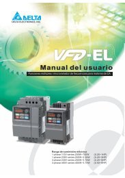
Preface<br />
Thank you for choosing DELTA’s high-performance VFD-VE Series. The VFD-VE Series is<br />
manufactured with high-quality components and materials and incorporates the latest microprocessor<br />
technology available.<br />
This manual is to be used for the installation, parameter setting, troubleshooting, and daily<br />
maintenance of the AC motor drive. To guarantee safe operation of the equipment, read the following<br />
safety guidelines before connecting power to the AC motor drive. Keep this operating manual at hand<br />
and distribute to all users for reference.<br />
To ensure the safety of operators and equipment, only qualified personnel familiar with AC motor<br />
drive are to do installation, start-up and maintenance. Always read this manual thoroughly before<br />
using VFD-VE series AC Motor Drive, especially the WARNING, DANGER and CAUTION notes.<br />
Failure to comply may result in personal injury and equipment damage. If you have any questions,<br />
please contact your dealer.<br />
PLEASE READ PRIOR TO INSTALLATION FOR SAFETY.<br />
DANGER!<br />
1. AC input power must be disconnected before any wiring to the AC motor drive is made.<br />
2. A charge may still remain in the DC-link capacitors with hazardous voltages, even if the power<br />
has been turned off. To prevent personal injury, please ensure that power has turned off before<br />
opening the AC motor drive and wait ten minutes for the capacitors to discharge to safe voltage<br />
levels.<br />
3. Never reassemble internal components or wiring.<br />
4. The AC motor drive may be destroyed beyond repair if incorrect cables are connected to the<br />
input/output terminals. Never connect the AC motor drive output terminals U/T1, V/T2, and<br />
W/T3 directly to the AC mains circuit power supply.<br />
5. Ground the VFD-VE using the ground terminal. The grounding method must comply with the<br />
laws of the country where the AC motor drive is to be installed. Refer to the Basic Wiring<br />
Diagram.<br />
6. VFD-VE series is used only to control variable speed of 3-phase induction motors, NOT for 1phase<br />
motors or other purpose.<br />
7. VFD-VE series shall NOT be used for life support equipment or any life safety situation.
WARNING!<br />
1. DO NOT use Hi-pot test for internal components. The semi-conductor used in AC motor drive<br />
easily damage by high-voltage.<br />
2. There are highly sensitive MOS components on the printed circuit boards. These components<br />
are especially sensitive to static electricity. To prevent damage to these components, do not<br />
touch these components or the circuit boards with metal objects or your bare hands.<br />
3. Only qualified persons are allowed to install, wire and maintain AC motor drives.<br />
CAUTION!<br />
1. Some parameters settings can cause the motor to run immediately after applying power.<br />
2. DO NOT install the AC motor drive in a place subjected to high temperature, direct sunlight,<br />
high humidity, excessive vibration, corrosive gases or liquids, or airborne dust or metallic<br />
particles.<br />
3. Only use AC motor drives within specification. Failure to comply may result in fire, explosion or<br />
electric shock.<br />
4. To prevent personal injury, please keep children and unqualified people away from the<br />
equipment.<br />
5. When the motor cable between AC motor drive and motor is too long, the layer insulation of the<br />
motor may be damaged. Please use a frequency inverter duty motor or add an AC output<br />
reactor to prevent damage to the motor. Refer to appendix B Reactor for details.<br />
6. The rated voltage for AC motor drive must be ≤ 240V (≤ 480V for 460V models) and the mains<br />
supply current capacity must be ≤ 5000A RMS (≤10000A RMS for the ≥ 40hp (30kW) models).
Table of Contents<br />
Preface ............................................................................................................. i<br />
Table of Contents .......................................................................................... iii<br />
Chapter 1 Introduction................................................................................ 1-1<br />
1.1 Receiving and Inspection ................................................................... 1-2<br />
1.1.1 Nameplate Information................................................................ 1-2<br />
1.1.2 Model Explanation ...................................................................... 1-2<br />
1.1.3 Series Number Explanation ........................................................ 1-3<br />
1.1.4 Drive Frames and Appearances ................................................. 1-3<br />
1.2 Preparation for Installation and Wiring ............................................... 1-4<br />
1.2.1 Ambient Conditions..................................................................... 1-4<br />
1.2.2 Remove Keypad ......................................................................... 1-6<br />
1.2.3 Remove Front Cover................................................................... 1-7<br />
1.2.4 Lifting .......................................................................................... 1-8<br />
1.3 Dimensions......................................................................................... 1-9<br />
Chapter 2 Installation and Wiring .............................................................. 2-1<br />
2.1 Wiring ................................................................................................. 2-2<br />
2.2 External Wiring ................................................................................... 2-4<br />
2.3 Main Circuit ........................................................................................ 2-5<br />
2.3.1 Main Circuit Connection.............................................................. 2-5<br />
2.3.2 Main Circuit Terminals ................................................................ 2-9
2.4 Control Terminals .............................................................................2-10<br />
Chapter 3 Digital Keypad Operation and Start Up ....................................3-1<br />
3.1 Digital Keypad KPV-CE01 ..................................................................3-1<br />
3.1.1 Description of the Digital Keypad KPV-CE01 ..............................3-1<br />
3.1.2 How to Operate the Digital Keypad KPV-CE01...........................3-3<br />
3.1.3 Dimension of the Digital Keypad .................................................3-5<br />
3.1.4 Reference Table for the LCD Display of the Digital Keypad........3-5<br />
3.1.5 Operation Method........................................................................3-6<br />
3.2 Tuning Operations ..............................................................................3-7<br />
3.2.1 Flow Chart...................................................................................3-7<br />
3.2.2 Explanations for the Tuning Steps.............................................3-10<br />
3.3.2.1 Step 1 ................................................................................3-10<br />
3.3.2.2 Step 2 ................................................................................3-11<br />
3.3.2.3 Step 3 ................................................................................3-12<br />
3.3.2.4 Step 4 ................................................................................3-13<br />
Chapter 4 Parameters..................................................................................4-1<br />
4.1 Summary of Parameter Settings.........................................................4-2<br />
4.2 Version Differences ..........................................................................4-26<br />
4.2.1 Version 2.02 ..............................................................................4-26<br />
4.2.2 Version 2.04 ..............................................................................4-29<br />
4.2.3 Version 2.05 ..............................................................................4-38<br />
4.3 Description of Parameter Settings ....................................................4-47<br />
Chapter 5 Troubleshooting .........................................................................5-1<br />
5.1 Over Current (OC) ..............................................................................5-1<br />
5.2 Ground Fault.......................................................................................5-2
5.3 Over Voltage (OV).............................................................................. 5-2<br />
5.4 Low Voltage (Lv) ................................................................................ 5-3<br />
5.5 Over Heat (oH1, oH2, oH3) ................................................................ 5-4<br />
5.6 Overload............................................................................................. 5-4<br />
5.7 Display of KPV-CE01 is Abnormal ..................................................... 5-5<br />
5.8 Phase Loss (PHL) .............................................................................. 5-5<br />
5.9 Motor cannot Run............................................................................... 5-6<br />
5.10 Motor Speed cannot be Changed..................................................... 5-7<br />
5.11 Motor Stalls during Acceleration....................................................... 5-8<br />
5.12 The Motor does not Run as Expected .............................................. 5-8<br />
5.13 Electromagnetic/Induction Noise ...................................................... 5-9<br />
5.14 Environmental Condition .................................................................. 5-9<br />
5.15 Affecting Other Machines ............................................................... 5-10<br />
Chapter 6 Fault Code Information and Maintenance................................ 6-1<br />
6.1 Fault Code Information....................................................................... 6-1<br />
6.1.1 Common Problems and Solutions............................................... 6-1<br />
6.1.2 Reset .......................................................................................... 6-6<br />
6.2 Maintenance and Inspections............................................................. 6-7<br />
Appendix A Specifications ........................................................................ A-1<br />
Appendix B Accessories ........................................................................... B-1<br />
B.1 All Brake Resistors & Brake Units Used in AC Motor Drives..............B-1<br />
B.1.1 Dimensions and Weights for Brake Resistors ............................B-4<br />
B.1.2 Specifications for Brake Unit ......................................................B-6<br />
B.1.3 Dimensions for Brake Unit..........................................................B-7
B.2 No-fuse Circuit Breaker Chart ........................................................... B-9<br />
B.3 Fuse Specification Chart ................................................................. B-10<br />
B.4 AC Reactor...................................................................................... B-11<br />
B.4.1 AC Input Reactor Recommended Value ...................................B-11<br />
B.4.2 AC Output Reactor Recommended Value ................................B-11<br />
B.4.3 Applications for AC Reactor......................................................B-13<br />
B.5 Zero Phase Reactor (RF220X00A) ................................................. B-15<br />
B.6 DC Choke Recommended Values................................................... B-16<br />
B.7 Remote Controller RC-01................................................................ B-17<br />
B.8 PG Card (for Encoder) .................................................................... B-18<br />
B.8.1 EMV-PG01X .............................................................................B-18<br />
B.8.2 EMV-PG01O.............................................................................B-22<br />
B.8.3 EMV-PG01L..............................................................................B-26<br />
B.9 AMD-EMI Filter Cross Reference .................................................... B-30<br />
B.9.1 Dimensions ...............................................................................B-33<br />
B.10 Multi-function I/O Extension Card.................................................. B-40<br />
B.10.1 Functions ................................................................................B-40<br />
B.10.2 Dimensions .............................................................................B-42<br />
B.10.3 Wiring......................................................................................B-42<br />
Appendix C How to Select the Right AC Motor Drive.............................. C-1<br />
C.1 Capacity Formulas ............................................................................ C-1<br />
C.2 General Precaution ........................................................................... C-3<br />
C.3 How to Choose a Suitable Motor....................................................... C-5
Chapter 1 Introduction<br />
The AC motor drive should be kept in the shipping carton or crate before installation. In order to retain<br />
the warranty coverage, the AC motor drive should be stored properly when it is not to be used for an<br />
extended period of time. Storage conditions are:<br />
CAUTION!<br />
1. Store in a clean and dry location free from direct sunlight or corrosive fumes.<br />
2. Store within an ambient temperature range of -10 ° C to +40 ° C.<br />
3. Store within a relative humidity range of 0% to 90% and non-condensing environment.<br />
4. Store within an air pressure range of 86 kPA to 106kPA.<br />
5. DO NOT place on the ground directly. It should be stored properly. Moreover, if the surrounding<br />
environment is humid, you should put exsiccator in the package.<br />
6. DO NOT store in an area with rapid changes in temperature. It may cause condensation and<br />
frost.<br />
7. If the AC motor drive is stored for more than 3 months, the temperature should not be higher<br />
than 30 °C. Storage longer than one year is not recommended, it could result in the degradation<br />
of the electrolytic capacitors.<br />
8. When the AC motor drive is not used for longer time after installation on building sites or places<br />
with humidity and dust, it’s best to move the AC motor drive to an environment as stated above.<br />
Revision Dec. 2008, 04VE, SW V2.05 1-1
Chapter 1 Introduction|<br />
1.1 Receiving and Inspection<br />
This VFD-VE AC motor drive has gone through rigorous quality control tests at the factory before<br />
shipment. After receiving the AC motor drive, please check for the following:<br />
� Check to make sure that the package includes an AC motor drive, the User <strong>Manual</strong>/Quick<br />
Start and CD.<br />
� Inspect the unit to assure it was not damaged during shipment.<br />
� Make sure that the part number indicated on the nameplate corresponds with the part<br />
number of your order.<br />
1.1.1 Nameplate Information<br />
Example for 5HP/3.7kW 3-phase 230V AC motor drive<br />
AC Drive Model<br />
Input Spec.<br />
Output Spec.<br />
Output Frequency Range<br />
Enclosure type<br />
Serial Number & Bar Code<br />
1.1.2 Model Explanation<br />
MODE : VFD037V23A-2<br />
INPUT : 3PH 200-240V 50/60Hz 19.6A<br />
OUTPUT : 3PH 0-240V 17A 6.5kVA 5HP<br />
Freq. Range : 0.00~600.00Hz<br />
ENCLOSURE: TYPE 1<br />
037V23A2T6360001<br />
VFD 037 V 23 A-2<br />
VFD-VE Series<br />
Version Type<br />
Mains Input Voltage<br />
23: 230V Three phase 43: 460V Three phase<br />
Vector Series<br />
Applicable motor capacity<br />
007: 1 HP(0.7kW) 150: 20HP(15kW)<br />
022: 3 HP(2.2kW) 220: 30 HP(22kW)<br />
037: 5 HP(3.7kW) 300: 40HP(30kW)<br />
055: 7.5HP(5.5kW) 370: 50 HP(37kW)<br />
075: 10 HP(7.5kW) 450: 60HP(45kW)<br />
110: 15 HP(11kW) 550: 75HP(55kW)<br />
750: 100HP(75kW)<br />
Series Name ( Variable Frequency Drive)<br />
1-2 Revision Dec. 2008, 04VE, SW V2.05
1.1.3 Series Number Explanation<br />
037V23A2 T 7 36<br />
230V 3-phase 5HP(3.7kW)<br />
Chapter 1 Introduction|<br />
Production number<br />
Production week<br />
Production year 2007<br />
Production factory<br />
(T: Taoyuan, W: Wujian)<br />
Model<br />
If the nameplate information does not correspond to your purchase order or if there are<br />
any problems, please contact your distributor.<br />
1.1.4 Drive Frames and Appearances<br />
1-5HP/0.75-3.7kW (Frame B) 7.5-15HP/5.5-11kW (Frame C)<br />
Revision Dec. 2008, 04VE, SW V2.05 1-3
Chapter 1 Introduction|<br />
15-30HP/11-22kW (Frame D) 40-100HP/30-75kW (Frame E)<br />
Frame Power range Models<br />
B (B1) 1-3hp (0.75-2.2kW)<br />
VFD007V23A/43A-2, VFD015V23A/43A-2,<br />
VFD022V23A/43A-2<br />
B (B2) 5hp (3.7kW) VFD037V23A/43A-2<br />
C 7.5-15hp (5.5-11kW) VFD055V23A/43A-2, VFD075V23A/43A-2, VFD110V43B-2<br />
D 15-30hp (11-22kW)<br />
VFD110V23A/43A-2, VFD150V23A/43A-2,<br />
VFD185V23A/43A-2, VFD220V23A/43A-2<br />
E (E1) 40-60hp (30-45kW) VFD300V43A-2, VFD370V43A-2, VFD450V43A-2<br />
E (E2) 40-100hp (30-75kW)<br />
VFD300V23A-2, VFD370V23A-2, VFD550V43C-2,<br />
VFD750V43C-2<br />
Please refer to Chapter 1.3 for exact dimensions.<br />
1.2 Preparation for Installation and Wiring<br />
1.2.1 Ambient Conditions<br />
Install the AC motor drive in an environment with the following conditions:<br />
1-4 Revision Dec. 2008, 04VE, SW V2.05
Operation<br />
Air Temperature: -10 ~ +40°C (14 ~ 122°F)<br />
Relative Humidity:
Chapter 1 Introduction|<br />
CAUTION!<br />
1. Operating, storing or transporting the AC motor drive outside these conditions may cause<br />
damage to the AC motor drive.<br />
2. Failure to observe these precautions may void the warranty!<br />
3. Mount the AC motor drive vertically on a flat vertical surface object by screws. Other directions<br />
are not allowed.<br />
4. The AC motor drive will generate heat during operation. Allow sufficient space around the unit<br />
for heat dissipation.<br />
5. The heat sink temperature may rise to 90°C when running. The material on which the AC motor<br />
drive is mounted must be noncombustible and be able to withstand this high temperature.<br />
6. When AC motor drive is installed in a confined space (e.g. cabinet), the surrounding<br />
temperature must be within -10 ~ 40°C with good ventilation. DO NOT install the AC motor<br />
drive in a space with bad ventilation.<br />
7. When installing multiple AC more drives in the same cabinet, they should be adjacent in a row<br />
with enough space in-between. When installing one AC motor drive below another one, use a<br />
metal separation between the AC motor drives to prevent mutual heating.<br />
8. Prevent fiber particles, scraps of paper, saw dust, metal particles, etc. from adhering to the<br />
heatsink.<br />
1.2.2 Remove Keypad<br />
1-5HP/0.75-3.7kW (Frame B) 7.5-15HP/5.5-11kW (Frame C)<br />
1-6 Revision Dec. 2008, 04VE, SW V2.05
Chapter 1 Introduction|<br />
15-30HP/11-22kW (Frame D) 40-100HP/30-75kW (Frame E)<br />
1.2.3 Remove Front Cover<br />
1-5HP/0.75-3.7kW (Frame B) 7.5-15HP/5.5-11kW (Frame C)<br />
Revision Dec. 2008, 04VE, SW V2.05 1-7
Chapter 1 Introduction|<br />
15-30HP/11-22kW (Frame D) 40-100HP/30-75kW (Frame E)<br />
1.2.4 Lifting<br />
Please carry only fully assembled AC motor drives as shown in the following.<br />
For 40-100HP (Frame E and E1)<br />
Step 1 Step 2<br />
1-8 Revision Dec. 2008, 04VE, SW V2.05
Step 3 Step 4<br />
1.3 Dimensions<br />
Chapter 1 Introduction|<br />
Revision Dec. 2008, 04VE, SW V2.05 1-9
Chapter 1 Introduction|<br />
Frame B<br />
W<br />
W1<br />
H1<br />
H<br />
1-10 Revision Dec. 2008, 04VE, SW V2.05<br />
S1<br />
D<br />
S2<br />
D1<br />
D2<br />
Unit: mm[inch]<br />
Frame W W1 H H1 D D1 D2 S1 S2<br />
B1<br />
B2<br />
150.0<br />
[5.91]<br />
150.0<br />
[5.91]<br />
NOTE<br />
135.0<br />
[5.32]<br />
135.0<br />
[5.32]<br />
260.0<br />
[10.24]<br />
272.1<br />
[10.72]<br />
244.3<br />
[9.63]<br />
244.3<br />
[9.63]<br />
160.2<br />
[6.31]<br />
183.7<br />
[7.24]<br />
67.0<br />
[2.64]<br />
67.0<br />
[2.64]<br />
4.0<br />
[0.16]<br />
4.0<br />
[0.16]<br />
Frame B1: VFD007V23A/43A-2, VFD015V23A/43A-2, VFD022V23A/43A-2<br />
Frame B2: VFD037V23A/43A-2<br />
8.0<br />
[0.32]<br />
8.0<br />
[0.32]<br />
6.5<br />
[0.26]<br />
6.5<br />
[0.26]
Frame C<br />
W<br />
W1<br />
H1<br />
H<br />
Chapter 1 Introduction|<br />
Revision Dec. 2008, 04VE, SW V2.05 1-11<br />
D<br />
S1 S2<br />
Unit: mm[inch]<br />
Frame W W1 H H1 D - - S1 S2<br />
C<br />
200.0<br />
[7.88]<br />
NOTE<br />
185.6<br />
[7.31]<br />
323.0<br />
[12.73]<br />
244.3<br />
[9.63]<br />
160.2<br />
[6.31]<br />
- -<br />
Frame C: VFD055V23A/43A-2, VFD075V23A/43A-2, VFD110V43B-2<br />
7.0<br />
[0.28]<br />
7.0<br />
[0.28]
Chapter 1 Introduction|<br />
Frame D<br />
W<br />
W1<br />
H1<br />
H<br />
1-12 Revision Dec. 2008, 04VE, SW V2.05<br />
D<br />
S1<br />
D1<br />
D2<br />
Unit: mm[inch]<br />
Frame W W1 H H1 D D1 D2 S1 -<br />
D<br />
250.0<br />
[9.85]<br />
NOTE<br />
226.0<br />
[8.90]<br />
408.2<br />
[16.07]<br />
384.0<br />
[15.13]<br />
205.4<br />
[8.08]<br />
110.0<br />
[4.33]<br />
10.0<br />
[0.39]<br />
10.0<br />
[0.39]<br />
Frame D: VFD110V23A/43A-2, VFD150V23A/43A-2, VFD185V23A/43A-2, VFD220V23A/43A-2<br />
-
Frame E<br />
H<br />
W D<br />
W1<br />
H2<br />
H1<br />
Chapter 1 Introduction|<br />
Revision Dec. 2008, 04VE, SW V2.05 1-13<br />
S1<br />
S3<br />
D1<br />
S2<br />
D2<br />
Unit: mm[inch]<br />
Frame W W1 H H1 H2 D D1 D2 S1 S2 S3<br />
E1<br />
370.0<br />
[14.57]<br />
335.0<br />
[13.19]<br />
-<br />
589.0<br />
[23.19]<br />
560.0<br />
[22.05]<br />
260.0<br />
[10.24]<br />
370.0 335.0 595.0 589.0 560.0 260.0<br />
E2<br />
[14.57] [13.19] [23.43] [23.19] [22.05] [10.24]<br />
NOTE<br />
132.5<br />
[5.22]<br />
132.5<br />
[5.22]<br />
18.0<br />
[0.71]<br />
18.0<br />
[0.71]<br />
Frame E1: VFD300V43A-2, VFD370V43A-2, VFD450V43A-2<br />
Frame E2: VFD300V23A-2, VFD370V23A-2, VFD550V43C-2, VFD750V43C-2<br />
13.0<br />
[0.51]<br />
13.0<br />
[0.51]<br />
13.0<br />
[0.51]<br />
13.0<br />
[0.51]<br />
18.0<br />
[0.71]<br />
18.0<br />
[0.71]
Chapter 1 Introduction|<br />
This page intentionally left blank<br />
1-14 Revision Dec. 2008, 04VE, SW V2.05
Chapter 2 Installation and Wiring<br />
After removing the front cover (see chapter 1.2.3 for details), check if the power and control terminals<br />
are clear. Be sure to observe the following precautions when wiring.<br />
� General Wiring Information<br />
Applicable Codes<br />
All VFD-VE series are Underwriters Laboratories, Inc. (UL) and Canadian Underwriters<br />
Laboratories (cUL) listed, and therefore comply with the requirements of the National<br />
Electrical Code (NEC) and the Canadian Electrical Code (CEC).<br />
Installation intended to meet the UL and cUL requirements must follow the instructions<br />
provided in “Wiring Notes” as a minimum standard. Follow all local codes that exceed UL<br />
and cUL requirements. Refer to the technical data label affixed to the AC motor drive and<br />
the motor nameplate for electrical data.<br />
The "Line Fuse Specification" in Appendix B, lists the recommended fuse part number for<br />
each VFD-VE Series part number. These fuses (or equivalent) must be used on all<br />
installations where compliance with U.L. standards is a required.<br />
CAUTION!<br />
1. Make sure that power is only applied to the R/L1, S/L2, T/L3 terminals. Failure to comply may<br />
result in damage to the equipment. The voltage and current should lie within the range as<br />
indicated on the nameplate.<br />
2. Check following items after finishing the wiring:<br />
A. Are all connections correct?<br />
B. No loose wires?<br />
C. No short-circuits between terminals or to ground?<br />
DANGER!<br />
1. A charge may still remain in the DC bus capacitors with hazardous voltages even if the power<br />
has been turned off. To prevent personal injury, please ensure that the power is turned off and<br />
wait ten minutes for the capacitors to discharge to safe voltage levels before opening the AC<br />
motor drive.<br />
2. All the units must be grounded directly to a common ground terminal to prevent lightning strike<br />
or electric shock.<br />
3. Only qualified personnel familiar with AC motor drives is allowed to perform installation, wiring<br />
and commissioning.<br />
4. Make sure that the power is off before doing any wiring to prevent electric shock.<br />
Revision Dec. 2008, 04VE, SW V2.05 2-1
Chapter 2 Installation and Wiring|<br />
2.1 Wiring<br />
Users must connect wires according to the circuit diagrams on the following pages. Do not plug a<br />
modem or telephone line to the RS-485 communication port or permanent damage may result. The<br />
pins 1 & 2 are the power supply for the optional copy keypad KPV-CE01 only and should not be used<br />
for RS-485 communication.<br />
Figure 1 for models of VFD-VE Series (15 HP/11kW and below)<br />
VFD007V23A/43A-2, VFD015V23A/43A-2, VFD022V23A/43A-2, VFD037V23A/43A-2,<br />
VFD055V23A/43A-2, VFD075V23A/43A-2, VFD110V43B-2, VFD110V23A/43A-2<br />
DC choke<br />
(optional)<br />
Brake resistor<br />
(optional)<br />
Fuse/NFB(No Fuse Breaker)<br />
R(L1)<br />
S(L2)<br />
T(L3)<br />
Recommended Circuit<br />
when power supply<br />
is turned OFF by a<br />
Jumper<br />
+1 +2/B1<br />
R(L1)<br />
S(L2)<br />
T(L3)<br />
E<br />
SA<br />
MC RB<br />
B2 -<br />
U(T1)<br />
V(T2)<br />
W(T3)<br />
E<br />
RA<br />
Motor<br />
IM<br />
3~<br />
fault output.<br />
If the fault occurs, the OFF ON<br />
contact will be ON to turn<br />
MC<br />
off the power and protect the power system.<br />
Factory setting:<br />
FWD/STOP<br />
SINK Mode<br />
REV/STOP<br />
Sink<br />
Sw1<br />
Multi-step 1<br />
Factory<br />
Source<br />
setting<br />
Multi-step 2<br />
Please refer to<br />
Figure 3 for wiring<br />
Multi-step 3<br />
of SINK mode and Multi-step 4<br />
SOURCEmode.<br />
No function<br />
No function<br />
Digital Signal Common<br />
* Don't apply the mains voltage directly<br />
to above terminals.<br />
ACI current/voltage selection<br />
ACI Switch<br />
3<br />
Make sure that power is OFF<br />
before changing the switch 5K 2<br />
setting.<br />
1<br />
0-20mA 0-10V<br />
RC<br />
RB<br />
RC<br />
+24V<br />
MRA<br />
FWD<br />
REV<br />
MRC<br />
MI1<br />
MI2 MO1<br />
MI3<br />
MI4<br />
MI5<br />
MO2<br />
MI6<br />
DCM<br />
MCM<br />
E<br />
DFM<br />
+10V<br />
Power supply<br />
+10V 20mA<br />
AVI<br />
Master Frequency DCM<br />
0 to 10V 47k<br />
ACI<br />
4~20mA/0~10V<br />
AUI<br />
-10~+10V<br />
ACM<br />
Analog Signal Common<br />
Multi-function contact output 1<br />
(relay)<br />
factory setting: fault indication<br />
Multi-function contact output 2<br />
(relay)<br />
48VDC 50mA<br />
factory setting:<br />
indicates that it is running<br />
Multi-function contact output 3<br />
(photocoupler)<br />
Multi-function contact output 4<br />
(photocoupler)<br />
Multi-function<br />
Photocoupler Output<br />
Digital Frequency Output<br />
Ter minal<br />
factory setting: 1:1<br />
Duty=50%, 10VDC<br />
Digital Signal Common<br />
DFM output signal selection<br />
DFM Switch<br />
Make sure that power is OFF<br />
before changing the switch<br />
setting.<br />
OC TP<br />
Analog Multi-function Output Terminal<br />
E<br />
AFM analog output selection<br />
AFM Switch<br />
Make sure that power is OFF<br />
before changing the switch<br />
setting.<br />
0-10V 0-20mA<br />
AFM 0~10VDC/2mA<br />
ACM<br />
Analog Signal common<br />
E<br />
RS-485 serial communication<br />
1: +EV<br />
2: GND For communication,<br />
3: SG- it needs to use<br />
4: SG+ VFD-USB01/IFD8500<br />
5: NC to connect to PC.<br />
6: NC<br />
Main circuit (power) terminals Control circuit terminals Shielded leads & Cable<br />
NOTE<br />
The brake resistor is built-in to model VFD110V43B.<br />
2-2 Revision Dec. 2008, 04VE, SW V2.05
Chapter 2 Installation and Wiring|<br />
Figure 2 for models of VFD-VE Series (20HP/15kW and above)<br />
VFD150V23A/43A-2, VFD185V23A/43A-2, VFD220V23A/43A-2, VFD300V43A-2, VFD370V43A-2,<br />
VFD450V43A-2, VFD300V23A-2, VFD370V23A-2, VFD550V43C-2, VFD750V43C-2<br />
DC choke brake unit<br />
(optional) (optional)<br />
VFDB<br />
brake resistor<br />
(optional)<br />
Fuse/NFB(No Fuse Breaker)<br />
Jumper<br />
-(minus sign)<br />
R(L1)<br />
S(L2)<br />
T(L3)<br />
+1<br />
R(L1)<br />
S(L2)<br />
T(L3)<br />
+2<br />
U(T1)<br />
V(T2)<br />
W(T3)<br />
Motor<br />
IM<br />
3~<br />
Recommended Circuit<br />
when power s upply<br />
is turned OFF by a<br />
SA<br />
MC<br />
E<br />
RB<br />
E<br />
RA<br />
fault output.<br />
If the fault occurs, the OFF ON<br />
contact will be ON to turn<br />
MC<br />
off the power and protect the power system.<br />
Factory setting:<br />
FWD/STOP<br />
SINK Mode<br />
REV/STOP<br />
Sink<br />
Sw1<br />
Multi-step 1<br />
Factory<br />
Source<br />
setting<br />
Multi-step 2<br />
Please refer to<br />
Multi-step 3<br />
Figure 3 for wiring<br />
of SINK mode and Multi-step 4<br />
SOURCEmode.<br />
No function<br />
No function<br />
Digital Signal Common<br />
* Don't apply the mains voltage directly<br />
to above terminals.<br />
ACI current/voltage selection<br />
ACI Switch<br />
3<br />
Make sure that power is OFF<br />
before changing the switch 5K 2<br />
setting.<br />
1<br />
0-20mA 0-10V<br />
RC<br />
RB<br />
RC<br />
+24V<br />
MRA<br />
FWD<br />
REV<br />
MRC<br />
MI1<br />
MI2 MO1<br />
MI3<br />
MI4<br />
MI5<br />
MO2<br />
MI6<br />
DCM<br />
MCM<br />
E<br />
DFM<br />
+10V<br />
Power supply<br />
+10V 20mA<br />
AVI<br />
Master Frequency DCM<br />
0 to 10V 47k<br />
ACI<br />
4~20mA/0~10V<br />
AUI<br />
-10~+10V<br />
ACM<br />
Analog Signal Common<br />
Multi-function contact output 1<br />
(relay)<br />
factory setting: fault indication<br />
Multi-function contact output 2<br />
(relay)<br />
48VDC 50mA<br />
factory setting:<br />
indicates that it is running<br />
Multi-function contact output 3<br />
(photocoupler)<br />
Multi-function contact output 4<br />
(photocoupler)<br />
Multi-function<br />
Photocoupler Output<br />
Digital Frequency Output<br />
Terminal<br />
factory setting: 1:1<br />
Duty=50%, 10VDC<br />
Digital Signal Common<br />
DFM output signal selection<br />
DFM Switch<br />
Make sure that power is OFF<br />
before changing the switch<br />
setting.<br />
OC TP<br />
Analog Multi-function Output Terminal<br />
E<br />
AFM analog output selection<br />
AFM Switch<br />
Make sure that power is OFF<br />
before changing the switch<br />
setting.<br />
0-10V 0-20mA<br />
AFM 0~10VDC/2mA<br />
ACM<br />
Analog Signal common<br />
E<br />
RS-485 serial communication<br />
1: +EV<br />
2: GND For communication,<br />
3: SG- it needs to use<br />
4: SG+ VFD-USB01/IFD8500<br />
5: NC to connect to PC.<br />
6: NC<br />
Main circuit (power) terminals Control circuit terminals Shielded leads & Cable<br />
NOTE The brake resistor is built-in to model VFD110V43B.<br />
Revision Dec. 2008, 04VE, SW V2.05 2-3
Chapter 2 Installation and Wiring|<br />
Figure 3 Wiring for SINK(NPN) mode and SOURCE(PNP) mode<br />
CAUTION!<br />
SINK/NPN Mode<br />
Sink<br />
SW1<br />
Source<br />
Factory<br />
setting<br />
FWD/STOP<br />
REV/STOP<br />
Multi-step1<br />
Multi-step2<br />
Multi-step3<br />
Multi-step4<br />
No Function<br />
No Function<br />
Digital Signal Common<br />
*Don't apply the mains voltage directly<br />
to above terminals.<br />
SOURCE/PNP Mode<br />
Sink<br />
FWD/STOP<br />
SW1<br />
REV/STOP<br />
Source<br />
Multi-step1<br />
Multi-step2<br />
Multi-step3<br />
Factory<br />
setting Multi-step4<br />
No Function<br />
No Function<br />
*Don't apply the mains voltage directly<br />
to above terminals.<br />
+24V<br />
FWD<br />
REV<br />
MI1<br />
MI2<br />
MI3<br />
MI4<br />
MI5<br />
MI6<br />
DCM<br />
E<br />
+24V<br />
FWD<br />
REV<br />
MI1<br />
MI2<br />
MI3<br />
MI4<br />
MI5<br />
MI6<br />
DCM<br />
E<br />
1. The wiring of main circuit and control circuit should be separated to prevent erroneous actions.<br />
2. Please use shield wire for the control wiring and not to expose the peeled-off net in front of the<br />
terminal.<br />
3. Please use the shield wire or tube for the power wiring and ground the two ends of the shield<br />
wire or tube.<br />
2.2 External Wiring<br />
2-4 Revision Dec. 2008, 04VE, SW V2.05
Power Supply<br />
EMI Filter<br />
R/L1 S/L2 T/L3<br />
U/T1 V/T2 W/T3<br />
Motor<br />
2.3 Main Circuit<br />
FUSE/NFB<br />
Magnetic<br />
contactor<br />
Input AC<br />
Line Reactor<br />
+/B1<br />
B2<br />
-<br />
Zero-phase<br />
Reactor<br />
E<br />
Break resistor<br />
(optional)<br />
Zero-phase<br />
Reactor<br />
Output AC<br />
Line Reactor<br />
Break unit (optional)<br />
BR<br />
Break resistor<br />
(optional)<br />
2.3.1 Main Circuit Connection<br />
Power<br />
supply<br />
Chapter 2 Installation and Wiring|<br />
Items Explanations<br />
Fuse/NFB<br />
(Optional)<br />
Magnetic<br />
contactor<br />
(Optional)<br />
Input AC<br />
Line Reactor<br />
(Optional)<br />
Zero-phase<br />
Reactor<br />
(Ferrite Core<br />
Common<br />
Choke)<br />
(Optional)<br />
EMI filter<br />
(Optional)<br />
Brake<br />
Resistor<br />
(Optional)<br />
Output AC<br />
Line Reactor<br />
(Optional)<br />
Please follow the specific power<br />
supply requirements shown in<br />
Appendix A.<br />
There may be an inrush current<br />
during power up. Please check the<br />
chart of Appendix B and select the<br />
correct fuse with rated current. Use of<br />
an NFB is optional.<br />
Please do not use a Magnetic<br />
contactor as the I/O switch of the AC<br />
motor drive, as it will reduce the<br />
operating life cycle of the AC drive.<br />
Used to improve the input power<br />
factor, to reduce harmonics and<br />
provide protection from AC line<br />
disturbances (surges, switching<br />
spikes, short interruptions, etc.). AC<br />
line reactor should be installed when<br />
the power supply capacity is 500kVA<br />
or more or advanced capacity is<br />
activated .The wiring distance should<br />
be ≤ 10m. Refer to appendix B for<br />
details.<br />
Zero phase reactors are used to<br />
reduce radio noise especially when<br />
audio equipment is installed near the<br />
inverter. Effective for noise reduction<br />
on both the input and output sides.<br />
Attenuation quality is good for a wide<br />
range from AM band to 10MHz.<br />
Appendix B specifies the zero phase<br />
reactor. (RF220X00A)<br />
To reduce electromagnetic<br />
interference, please refer to Appendix<br />
B for more details.<br />
Used to reduce the deceleration time<br />
of the motor. Please refer to the chart<br />
in Appendix B for specific Brake<br />
Resistors.<br />
Motor surge voltage amplitude<br />
depends on motor cable length. For<br />
applications with long motor cable<br />
(>20m), it is necessary to install a<br />
reactor at the inverter output side<br />
Revision Dec. 2008, 04VE, SW V2.05 2-5
Chapter 2 Installation and Wiring|<br />
Figure 1 for the main terminals<br />
No-fuse breaker<br />
(NFB)<br />
R<br />
S<br />
T<br />
Figure 2 for the main terminals<br />
R<br />
S<br />
T<br />
No-fuse breaker<br />
(NFB)<br />
MC<br />
MC<br />
Br ak e res istor(O pti onal)<br />
+1 +2/B1 B2 -<br />
R(L1)<br />
U(T1)<br />
S(L2)<br />
V(T2)<br />
T(L3)<br />
W(T3)<br />
E<br />
E<br />
VFDB<br />
+1 +2 -<br />
R(L1)<br />
U(T1)<br />
S(L2)<br />
V(T2)<br />
T(L3)<br />
W(T3)<br />
E<br />
E<br />
Brak e res istor<br />
(optional)<br />
Terminal Symbol Explanation of Terminal Function<br />
R/L1, S/L2, T/L3 AC line input terminals (1-phase/3-phase)<br />
U/T1, V/T2, W/T3<br />
Motor<br />
IM<br />
3~<br />
Motor<br />
IM<br />
3~<br />
AC drive output terminals for connecting 3-phase<br />
induction motor<br />
+1, +2 Connections for DC Choke (optional)<br />
+2/B1, B2 Connections for Brake Resistor (optional)<br />
+2~(-), +2/B1~(-) Connections for External Brake Unit (VFDB series)<br />
Earth connection, please comply with local regulations.<br />
2-6 Revision Dec. 2008, 04VE, SW V2.05
Mains power terminals (R/L1, S/L2, T/L3)<br />
Chapter 2 Installation and Wiring|<br />
� Connect these terminals (R/L1, S/L2, T/L3) via a no-fuse breaker or earth leakage breaker to<br />
3-phase AC power (some models to 1-phase AC power) for circuit protection. It is<br />
unnecessary to consider phase-sequence.<br />
� It is recommended to add a magnetic contactor (MC) in the power input wiring to cut off<br />
power quickly and reduce malfunction when activating the protection function of AC motor<br />
drives. Both ends of the MC should have an R-C surge absorber.<br />
� Please make sure to fasten the screw of the main circuit terminals to prevent sparks which is<br />
made by the loose screws due to vibration.<br />
� Please use voltage and current within the regulation shown in Appendix A.<br />
� When using leakage-current breaker to prevent leakage current,<br />
� Do NOT run/stop AC motor drives by turning the power ON/OFF. Run/stop AC motor drives<br />
by RUN/STOP command via control terminals or keypad. If you still need to run/stop AC<br />
drives by turning power ON/OFF, it is recommended to do so only ONCE per hour.<br />
� Do NOT connect 3-phase models to a 1-phase power source.<br />
Output terminals for main circuit (U, V, W)<br />
� When the AC drive output terminals U/T1, V/T2, and W/T3 are connected to the motor<br />
terminals U/T1, V/T2, and W/T3, respectively, the motor will rotate counterclockwise (as<br />
viewed on the shaft end of the motor) when a forward operation command is received. To<br />
permanently reverse the direction of motor rotation, switch over any of the two motor leads.<br />
Forward<br />
running<br />
� DO NOT connect phase-compensation capacitors or surge absorbers at the output terminals<br />
of AC motor drives.<br />
� With long motor cables, high capacitive switching current peaks can cause over-current, high<br />
leakage current or lower current readout accuracy. To prevent this, the motor cable should<br />
be less than 20m for 3.7kW models and below. And the cable should be less than 50m for<br />
5.5kW models and above. For longer motor cables use an AC output reactor.<br />
� Use well-insulated motor, suitable for inverter operation.<br />
Terminals [+1, +2] for connecting DC reactor<br />
DC reactor<br />
Jumper<br />
+1<br />
Revision Dec. 2008, 04VE, SW V2.05 2-7
Chapter 2 Installation and Wiring|<br />
� To improve power factor and reduce harmonics connect a DC reactor between terminals [+1,<br />
+2]. Please remove the jumper before connecting the DC reactor.<br />
NOTE Models of 15kW and above have a built-in DC reactor.<br />
Terminals [+2/B1, B2] for connecting brake resistor and terminals [+1, +2/B1] for<br />
connecting external brake unit<br />
Brake resistor(optional)<br />
BR<br />
Brake unit(optional)<br />
VFDB<br />
Refer to Appendix B for the use of<br />
BR<br />
spec ial braking resis tor/unit<br />
+2/B1 B2<br />
+2/B1<br />
-<br />
� Connect a brake resistor or brake unit in applications with frequent deceleration ramps, short<br />
deceleration time, too low brake torque or requiring increased brake torque.<br />
� If the AC motor drive has a built-in brake chopper (all models of 11kW and below), connect<br />
the external brake resistor to the terminals [+2/B1, B2].<br />
� Models of 15kW and above don’t have a built-in brake chopper. Please connect an external<br />
optional brake unit (VFDB-series) and brake resistor. Refer to VFDB series user manual for<br />
details.<br />
� Connect the terminals [+(P), -(N)] of the brake unit to the AC motor drive terminals<br />
[+2(+2/B1), (-)]. The length of wiring should be less than 5m with twisted cable.<br />
� When not used, please leave the terminals [+2/B1, -] open.<br />
WARNING!<br />
1. Short-circuiting [B2] or [-] to [+2/B1] can damage the AC motor drive.<br />
Grounding terminals ( )<br />
� Make sure that the leads are connected correctly and the AC drive is properly grounded.<br />
(Ground resistance should not exceed 0.1Ω.)<br />
� Use ground leads that comply with local regulations and keep them as short as possible.<br />
� Multiple VFD-VE units can be installed in one location. All the units should be grounded<br />
directly to a common ground terminal, as shown in the figure below. Ensure there are no<br />
ground loops.<br />
excellent good not allowed<br />
2-8 Revision Dec. 2008, 04VE, SW V2.05
2.3.2 Main Circuit Terminals<br />
Frame B<br />
Frame C<br />
+1 +2 B1 - B2 U/T1 V/T2 W/T3<br />
Screw Torque :<br />
18Kgf-cm<br />
Wire Gauge :<br />
18~10AWG<br />
POWER<br />
R/L1 S/L2 T/L3<br />
IM MOTOR<br />
3<br />
Chapter 2 Installation and Wiring|<br />
Main circuit terminals<br />
R/L1, S/L2, T/L3, U/T1, V/T2, W/T3, , +1, +2/B1, -, B2<br />
Models<br />
VFD007V23A-2<br />
VFD007V43A-2<br />
VFD015V23A-2<br />
Wire Torque Wire Type<br />
VFD015V43A-2<br />
VFD022V23A-2<br />
VFD022V43A-2<br />
VFD037V23A-2<br />
VFD037V43A-2<br />
14-10 AWG<br />
(2.1-5.3mm 2 )<br />
18kgf-cm<br />
(15.6in-lbf)<br />
Stranded<br />
copper only,<br />
75 o C<br />
Main circuit terminals<br />
R/L1, S/L2, T/L3, U/T1, V/T2, W/T3, , +1, +2/B1, -, B2<br />
Models<br />
VFD055V23A-2<br />
Wire Torque Wire Type<br />
VFD075V23A-2<br />
VFD110V43B-2<br />
VFD055V43A-2<br />
VFD075V43A-2<br />
12-8 AWG<br />
(3.3-8.4mm 2 )<br />
30kgf-cm<br />
(26in-lbf)<br />
Stranded<br />
copper only,<br />
75 o C<br />
Revision Dec. 2008, 04VE, SW V2.05 2-9
Chapter 2 Installation and Wiring|<br />
Frame D<br />
R/L1 S/L2 T/L3 +1 +2 - V/T2 W/T3<br />
POWER DC ( + ) DC ( - ) IM<br />
3 MOTOR<br />
Frame E<br />
CHARGE<br />
POWER<br />
ALARM<br />
R/L1 S/L2 T/L3 +1 +2 U/T1 V/T2 W/T3<br />
Screw Torque:<br />
IM POWER 200kgf-cm (173in-lbf)<br />
3 MOTOR<br />
NOTE<br />
Main circuit terminals<br />
R/L1, S/L2, T/L3, U/T1, V/T2, W/T3, , +1, +2, -<br />
Models<br />
VFD110V23A-2<br />
VFD110V43A-2<br />
VFD150V43A-2<br />
Wire Torque Wire Type<br />
VFD150V23A-2<br />
VFD185V23A-2<br />
VFD185V43A-2<br />
VFD220V43A-2<br />
VFD220V23A-2<br />
8-2 AWG<br />
(8.4-33.6mm 2 )<br />
30kgf-cm<br />
(26in-lbf)<br />
Stranded<br />
copper only,<br />
75 o C<br />
Main circuit terminals<br />
R/L1, S/L2, T/L3, U/T1, V/T2, W/T3, , +1, +2, -<br />
Models Wire Torque Wire Type<br />
VFD300V43A-2<br />
VFD370V43A-2<br />
VFD450V43A-2<br />
4-2 AWG<br />
VFD300V23A-2<br />
(21.2-33.6mm<br />
VFD370V23A-2<br />
2 )<br />
VFD550V43C-2<br />
VFD750V43C-2<br />
# To connect 6 AWG (13.3 mm 2 ) wires, use Recognized Ring Terminals<br />
2.4 Control Terminals<br />
57kgf-cm<br />
(49in-lbf)<br />
200kgf-cm<br />
(173in-lbf)<br />
Stranded<br />
copper<br />
only, 75 o C<br />
2-10 Revision Dec. 2008, 04VE, SW V2.05
Chapter 2 Installation and Wiring|<br />
Circuit diagram for digital inputs (SINK current 16mA.)<br />
SINK Mode<br />
SOURCE Mode<br />
multi-input<br />
terminal<br />
MRA<br />
DCM<br />
RA<br />
MRC RB<br />
+24<br />
Internal Circuit<br />
Multi-Input<br />
Terminal<br />
Revision Dec. 2008, 04VE, SW V2.05 2-11<br />
+24V<br />
The Position of the Control Terminals<br />
DCM<br />
Internal Circuit<br />
RC<br />
MCM +24V FWD MI1 MI3 MI5 DFM +10V AVI ACM<br />
MO1 MO2 DCM REV MI2 MI4 MI6 AFM AUI<br />
ACI
Chapter 2 Installation and Wiring|<br />
Terminal symbols and functions<br />
Terminal<br />
Symbol<br />
Terminal Function<br />
FWD Forward-Stop Command<br />
REV Reverse-Stop Command<br />
Factory Settings (SINK)<br />
ON: Connect to DCM<br />
ON: Run in FWD direction<br />
OFF: Stop acc. to Stop Method<br />
ON: Run in REV direction<br />
OFF: Stop acc. to Stop Method<br />
+24V DC Voltage Source +24VDC, 80mA, used for SOURCE mode.<br />
MI1 Multi-function Input 1<br />
MI2 Multi-function Input 2<br />
MI3 Multi-function Input 3<br />
MI4 Multi-function Input 4<br />
MI5 Multi-function Input 5<br />
MI6 Multi-function Input 6<br />
DFM<br />
Digital Frequency Meter<br />
(Open Collector Output)<br />
DFM-DCM<br />
Max: 48V<br />
50mA<br />
J5<br />
50%<br />
internal circuit<br />
DCM Digital Signal Common<br />
RA<br />
RB<br />
100%<br />
Multi-function Relay Output 1<br />
(N.O.) a<br />
Multi-function Relay Output 1<br />
(N.C.) b<br />
RC Multi-function Relay Common<br />
MRA<br />
Multi-function Relay Output 2<br />
(N.O.) a<br />
MRC Multi-function Relay Common<br />
Refer to Pr.02-01 to Pr.02-06 for programming<br />
the Multi-function Inputs.<br />
ON: the activation current is 6.5mA. OFF:<br />
leakage current tolerance is 10μA.<br />
Pulse voltage output monitor signal,<br />
proportional to output frequency<br />
Duty-cycle: 50%<br />
Ratio: Pr.02-18<br />
Min. load: 4.7kΩ<br />
Max. current: 50mA<br />
Max. voltage: 48Vdc<br />
Jumper: DFM jumper, factory<br />
setting is OC<br />
Common for digital inputs and used for SINK<br />
mode.<br />
Resistive Load:<br />
5A(N.O.)/3A(N.C.) 240VAC<br />
5A(N.O.)/3A(N.C.) 24VDC<br />
Inductive Load:<br />
1.5A(N.O.)/0.5A(N.C.) 240VAC<br />
1.5A(N.O.)/0.5A(N.C.) 24VDC<br />
To output monitor signal, including in operation,<br />
frequency arrival, overload and etc.<br />
Refer to Pr.02-11~02-12 for programming<br />
2-12 Revision Dec. 2008, 04VE, SW V2.05
Terminal<br />
Symbol<br />
Terminal Function<br />
Chapter 2 Installation and Wiring|<br />
Factory Settings (SINK)<br />
ON: Connect to DCM<br />
+10V Potentiometer Power Supply +10VDC 20mA (variable resistor 3-5kohm)<br />
MCM<br />
MO1<br />
MO2<br />
AVI<br />
ACI<br />
AUI<br />
Multi-function Output<br />
Common (Photocoupler)<br />
Multi-function Output 1<br />
(Photocoupler)<br />
Multi-function Output 2<br />
(Photocoupler)<br />
Analog voltage Input<br />
+10V<br />
AVI<br />
ACM<br />
AVI circuit<br />
internal circuit<br />
Analog current Input<br />
ACI circuit<br />
ACI<br />
ACM<br />
internal circuit<br />
Max. 48VDC 50mA<br />
Maximum 48VDC, 50mA<br />
Refer to Pr.02-13 to Pr.02-14 for programming<br />
MO1~MO2-DCM<br />
MO1~MO2<br />
Revision Dec. 2008, 04VE, SW V2.05 2-13<br />
MCM<br />
Internal Circuit<br />
Impedance: 200kΩ<br />
Max: 48Vdc<br />
50mA<br />
Resolution: 12 bits<br />
Range: 0 ~ 10VDC = 0 ~ Max. Output<br />
Frequency (Pr.01-00)<br />
Set-up: Pr.03-00 ~ Pr.03-02<br />
Impedance: 250Ω<br />
Resolution: 12 bits<br />
Range: 4 ~ 20mA/0~10V =<br />
0 ~ Max. Output Frequency<br />
(Pr.01-00)<br />
Set-up: Pr.03-00 ~ Pr.03-02<br />
Jumper: ACI jumper, factory setting is<br />
4-20mA<br />
Auxiliary analog voltage input<br />
+10<br />
~ AUI circuit<br />
-10V<br />
Impedance:<br />
Resolution:<br />
Range:<br />
200kΩ<br />
12 bits<br />
-10 ~ +10VDC =<br />
0 ~ Max. Output Frequency<br />
AUI<br />
(Pr.01-00)<br />
ACM<br />
internal circuit<br />
Set-up: Pr.03-00 ~ Pr.03-02
Chapter 2 Installation and Wiring|<br />
Terminal<br />
Symbol<br />
AFM<br />
ACM<br />
Terminal Function<br />
Analog output meter<br />
AFM<br />
ACM<br />
Analog control signal<br />
(common)<br />
0~20mA<br />
Factory Settings (SINK)<br />
ON: Connect to DCM<br />
Impedance: 18.5kΩ (voltage output)<br />
1.1mΩ (current output)<br />
Output current 20mA max<br />
Resolution: max. frequency corresponds to<br />
0-10V<br />
Range: 0 ~ 10V/0 ~ 20mA<br />
Function: Pr.03-18<br />
Switch: AFM switch, factory setting is 0-<br />
10V<br />
Common for AVI, ACI, AUI, AFM<br />
*Control signal wiring size: 18 AWG (0.75 mm 2 ) with shielded wire.<br />
Analog input terminals (AVI, ACI, AUI, ACM)<br />
� Analog input signals are easily affected by external noise. Use shielded wiring and keep it as<br />
short as possible (
General<br />
Chapter 2 Installation and Wiring|<br />
� Keep control wiring as far as possible from the power wiring and in separate conduits to<br />
avoid interference. If necessary let them cross only at 90º angle.<br />
� The AC motor drive control wiring should be properly installed and not touch any live power<br />
wiring or terminals.<br />
NOTE<br />
� If a filter is required for reducing EMI (Electro Magnetic Interference), install it as close as<br />
possible to AC drive. EMI can also be reduced by lowering the Carrier Frequency.<br />
� When using a GFCI (Ground Fault Circuit Interrupter), select a current sensor with sensitivity<br />
of 200mA, and not less than 0.1-second detection time to avoid nuisance tripping.<br />
DANGER!<br />
Damaged insulation of wiring may cause personal injury or damage to circuits/equipment if it comes<br />
in contact with high voltage.<br />
The specification for the control terminals<br />
The Position of the Control Terminals<br />
MRA RA<br />
MRC RB<br />
NOTE<br />
RC<br />
MCM +24V FWD MI1 MI3 MI5 DFM +10V AVI ACM<br />
MO1 MO2 DCM REV MI2 MI4 MI6 AFM AUI<br />
Frame Torque Wire<br />
Revision Dec. 2008, 04VE, SW V2.05 2-15<br />
ACI<br />
B, C, D, E, E1 8 kgf-cm (6.9 in-lbf) 22-14 AWG (0.3-2.1mm 2 )<br />
Frame B: VFD007V23A/43A-2, VFD015V23A/43A-2, VFD022V23A/43A-2, VFD037V23A/43A-2;<br />
Frame C: VFD055V23A/43A-2, VFD075V23A/43A-2, VFD110V43B-2,<br />
Frame D: VFD110V23A/43A-2, VFD150V23A/43A-2, VFD185V23A/43A-2, VFD220V23A/43A-2<br />
Frame E: VFD300V43A-2, VFD370V43A-2, VFD450V43A-2<br />
Frame E1: VFD300V23A-2, VFD370V23A-2, VFD550V43C-2, VFD750V43C-2
Chapter 3 Digital Keypad Operation and Start Up<br />
3.1 Digital Keypad KPV-CE01<br />
3.1.1 Description of the Digital Keypad KPV-CE01<br />
MODE Selection Key<br />
Press this key to view different<br />
operating values<br />
Left Key<br />
moves cursor to the left<br />
FWD/REV Direction Key<br />
RUN key<br />
F<br />
H<br />
U<br />
JOG<br />
KPV-CE01<br />
EXTPU<br />
STOP<br />
RUN RESET<br />
LED Display<br />
Display frequency, current, voltage<br />
and error, etc.<br />
Part Number<br />
Status Display<br />
Display of driver status<br />
STOP/RESET<br />
Revision Dec. 2008, 04VE, SW V2.05 3-1<br />
PU<br />
Display Message Descriptions<br />
Displays the AC drive Master Frequency.<br />
Right Key<br />
Moves the cursor right<br />
Displays the actual output frequency present at terminals U/T1, V/T2, and<br />
W/T3.<br />
User defined unit (where U = F x Pr.00-05)<br />
Displays the output current present at terminals U/T1, V/T2, and W/T3.<br />
The counter value (C).
Chapter 3 Digital Keypad Operation and Start Up|<br />
Display Message Descriptions<br />
Displays the selected parameter.<br />
Displays the actual stored value of the selected parameter.<br />
External Fault.<br />
Display “End” for approximately 1 second if input has been accepted by<br />
pressing key. After a parameter value has been set, the new<br />
value is automatically stored in memory. To modify an entry, use the<br />
, and keys.<br />
Display “Err”, if the input is invalid.<br />
3-2 Revision Dec. 2008, 04VE, SW V2.05
F<br />
H<br />
U<br />
Chapter 3 Digital Keypad Operation and Start Up|<br />
3.1.2 How to Operate the Digital Keypad KPV-CE01<br />
START<br />
F<br />
H<br />
U<br />
Selection mode<br />
To set parameters<br />
F<br />
H<br />
U<br />
To shift cursor<br />
START<br />
To modify data<br />
START<br />
F<br />
H<br />
U<br />
F<br />
H<br />
U<br />
NOTE: In the selection mode, press<br />
F<br />
H<br />
U<br />
F<br />
H<br />
U<br />
F<br />
H<br />
U<br />
MODE<br />
MODE<br />
F<br />
H<br />
U<br />
F<br />
H<br />
U<br />
F<br />
H<br />
U<br />
NOTE: In the parameter setting mode, you can press<br />
F<br />
H<br />
U<br />
F<br />
H<br />
U<br />
START<br />
MODE<br />
To switch display mode<br />
F<br />
H<br />
U<br />
F<br />
H<br />
U<br />
MODE MODE<br />
F<br />
H<br />
U<br />
MODE<br />
Revision Dec. 2008, 04VE, SW V2.05 3-3<br />
MODE<br />
to set the parameters.<br />
move to previous display<br />
F<br />
H<br />
U<br />
F<br />
H<br />
U<br />
F<br />
H<br />
U<br />
F<br />
H<br />
U<br />
F<br />
H<br />
U<br />
F<br />
H<br />
U<br />
F<br />
H<br />
U<br />
MODE<br />
F<br />
H<br />
U<br />
parameter set successfully<br />
to return to the selection mode.<br />
F<br />
H<br />
U<br />
parameter set error<br />
F<br />
H<br />
U<br />
F<br />
H<br />
U<br />
MODE<br />
GO START<br />
F<br />
H<br />
U
Chapter 3 Digital Keypad Operation and Start Up|<br />
F<br />
H<br />
U<br />
F<br />
H<br />
U<br />
F<br />
H<br />
U<br />
F<br />
H<br />
U<br />
To copy parameters 1<br />
Copy parameters from the AC Motor Drive to the KPV-CE01<br />
F<br />
H<br />
U<br />
F<br />
H<br />
U<br />
F<br />
H<br />
U<br />
F<br />
H<br />
U<br />
F<br />
H<br />
U<br />
F<br />
H<br />
U<br />
F<br />
H<br />
U<br />
F<br />
H<br />
U<br />
F<br />
H<br />
U<br />
F<br />
H<br />
U<br />
F<br />
H<br />
U<br />
start blinking It will display "End" to indicate that<br />
the first parameter is saved, then<br />
return to "rEAd0".<br />
To copy parameters 2<br />
F<br />
H<br />
U<br />
3-4 Revision Dec. 2008, 04VE, SW V2.05<br />
F<br />
H<br />
U<br />
F<br />
H<br />
U<br />
F<br />
H<br />
U<br />
F<br />
H<br />
U<br />
F<br />
H<br />
U<br />
F<br />
H<br />
U<br />
start blinking It will display "End" to indicate that<br />
about 2-3 seconds<br />
the second parameter is saved, then<br />
return to "rEAd1".<br />
Copy parameters from the KPV-CE01 to the AC Motor Drive<br />
about 2-3 seconds<br />
F<br />
H<br />
U<br />
start blinking<br />
F<br />
H<br />
U<br />
F<br />
H<br />
U<br />
F<br />
H<br />
U<br />
F<br />
H<br />
U<br />
F<br />
H<br />
U<br />
F<br />
H<br />
U<br />
F<br />
F<br />
H<br />
H<br />
U<br />
U<br />
It will display "End" to indicate that<br />
the first parameter is saved, then<br />
return to "SAvEv".<br />
F<br />
H<br />
U<br />
F<br />
F<br />
H<br />
H<br />
U<br />
U<br />
start blinking<br />
about 2-3 seconds<br />
F<br />
H<br />
U<br />
about 2-3 seconds<br />
F<br />
H<br />
U<br />
F<br />
F<br />
H<br />
H<br />
U<br />
U<br />
It will display "End" to indicate that<br />
the second parameter is saved, then<br />
return to "SAvEv".
3.1.3 Dimension of the Digital Keypad<br />
F<br />
H<br />
U<br />
JOG<br />
FWD<br />
REV<br />
RUN<br />
MODE<br />
KPV-CEO1<br />
RUN STOP JOGFWD REV EXT PU<br />
PU<br />
PROG<br />
DATA<br />
STOP<br />
RESET<br />
Chapter 3 Digital Keypad Operation and Start Up|<br />
3.1.4 Reference Table for the LCD Display of the Digital Keypad<br />
Digital 0 1 2 3 4 5 6 7 8 9<br />
LCD<br />
English<br />
alphabet<br />
LCD<br />
English<br />
alphabet<br />
LCD<br />
English<br />
alphabet<br />
LCD<br />
A b Cc d E F G Hh I Jj<br />
K L n Oo P q r S Tt U<br />
v Y Z<br />
Unit: mm [inch]<br />
Revision Dec. 2008, 04VE, SW V2.05 3-5<br />
LABEL 1
Chapter 3 Digital Keypad Operation and Start Up|<br />
3.1.5 Operation Method<br />
Refer to 3.1.2 How to operate the digital keypad KPV-CE01 and chapter 4 parameters for<br />
setting. Please choose a suitable method depending on application and operation rule. The<br />
operation is usually used as shown in the following table.<br />
Operation Method Frequency Source<br />
KPV-CE01 keypad<br />
Operate from<br />
external signal<br />
Operate from<br />
communication<br />
Factory setting:<br />
SINK Mode<br />
Sink<br />
Sw1<br />
Factory<br />
Source setting<br />
Please refer to<br />
Figure 3 for wiring<br />
of SINK mode and<br />
SOURCEmode.<br />
FWD/STOP<br />
REV/STOP<br />
Multi-step 1<br />
Multi-step 2<br />
Multi-step 3<br />
Multi-step 4<br />
No function<br />
No function<br />
Digital Signal Common<br />
* Don't apply the mains voltage directly<br />
to abov e terminals.<br />
ACI current/voltage selection<br />
ACI Switch<br />
3<br />
Make sure that power is OFF<br />
before changing the switch 5K 2<br />
setting.<br />
0-20mA 0-10V<br />
1<br />
Analog Multi-function Output Terminal<br />
AFM analog output selection<br />
AFM Switch<br />
Make sure that power is OFF<br />
before changing the switch<br />
setting.<br />
0-10V 0-20mA<br />
Main circuit (power) terminals<br />
Operation Command<br />
Source<br />
STOP<br />
RUN RESET<br />
+24V<br />
FWD<br />
REV<br />
MI1<br />
MI2<br />
MI3<br />
MI4<br />
MI5<br />
MI6<br />
DCM<br />
E<br />
+10V<br />
Power supply<br />
+10V 20mA<br />
AVI<br />
Master Frequency<br />
0 to 10V 47k<br />
ACI<br />
4~20mA/0~10V<br />
AUI<br />
-10~+10V<br />
ACM<br />
Analog Signal Common<br />
E<br />
AFM 0~10VDC/2mA<br />
ACM<br />
Analog Signal common<br />
E<br />
Control circuit terminals Shielded leads & Cable<br />
Please refer to the communication address 2000H and 2119H settings in the<br />
communication address definition.<br />
3-6 Revision Dec. 2008, 04VE, SW V2.05
3.2 Tuning Operations<br />
3.2.1 Flow Chart<br />
Take motor 1 as example<br />
Step 1<br />
Basic parameters settings<br />
Reset all parameters<br />
to factory setting<br />
Pr.00-02<br />
Setting the related<br />
information of IM motor<br />
Pr.01-00~01-02<br />
Pr.05-01~05-04<br />
If the motor and<br />
load can be<br />
separated<br />
YES<br />
run in low speed<br />
Check if output current<br />
is within (20~50%) of<br />
rated current<br />
YES<br />
Stop running<br />
Motor auto tuning<br />
Pr.05-00=1<br />
NO<br />
NO<br />
Chapter 3 Digital Keypad Operation and Start Up|<br />
Step 2 Motor tuning<br />
No-load current of motor<br />
Pr.05-05<br />
Motor auto tuning<br />
Pr.05-00=2<br />
If it displays "tun"<br />
during trial run<br />
Please contact<br />
motor supplier<br />
Revision Dec. 2008, 04VE, SW V2.05 3-7<br />
YES<br />
The motor tuning is<br />
finished after motor<br />
is stopped.<br />
Check if the value<br />
has been written<br />
into Pr.05-05~05-09<br />
NO<br />
If it displays "AUE",<br />
please check the<br />
wiring and parameter<br />
settings.
Chapter 3 Digital Keypad Operation and Start Up|<br />
Step 3 Trial run for FOCPG feedback control<br />
Selection of speed<br />
feedback card<br />
E MV-P G01X<br />
E MV-P G01O<br />
E MV-P G01L<br />
Encoder pulse<br />
Pr.10-00<br />
Encoder input type setting<br />
Pr.10-01<br />
Pr.00-10=3<br />
FOCPG control mode<br />
If the motor can run YES<br />
NO<br />
Stop trial run<br />
Check if PG card<br />
is nor mal<br />
3-8 Revision Dec. 2008, 04VE, SW V2.05<br />
NO<br />
Check if output<br />
current is normal<br />
YES<br />
Change the operation<br />
direction of motor<br />
Increase the<br />
frequency command<br />
Finish trial run<br />
YES<br />
NO<br />
Refer to chapter 6<br />
for fault c ode<br />
Check the setting<br />
of Pr.10-00<br />
If there is<br />
mechanical<br />
gear<br />
YES<br />
Check the setting of<br />
gear ratio (Pr.10-27~<br />
10-28)
Step 4 Inertia estimation<br />
Connect the load and motor<br />
Adjust accel./decel. time<br />
Pr.01-12~01-13<br />
Pr.11-00=2<br />
If it allows the motor<br />
to forward/reverse<br />
running<br />
YES<br />
Set the operation frequency<br />
to 2/3 of motor rated<br />
frequency<br />
operate the motor<br />
observe Pr.11-01<br />
and adjust the<br />
operation direction<br />
NO<br />
Chapter 3 Digital Keypad Operation and Start Up|<br />
adjust multi-step speed<br />
MI1=1, set Pr.04-00 to 1/5 of<br />
rated frequency and operation<br />
frequency to 4/5 of rated frequency<br />
operate the motor<br />
observe Pr.11-01 and<br />
set Pr.02-10 to 4 or 0<br />
Check if Pr.11-01<br />
setti ng is<br />
convergence<br />
Revision Dec. 2008, 04VE, SW V2.05 3-9<br />
YES<br />
Stop motor running<br />
record Pr.11-01<br />
Pr.11-00=0<br />
Finish trial run<br />
NO<br />
Check accel./decel. time<br />
and operation frequency<br />
setting
Chapter 3 Digital Keypad Operation and Start Up|<br />
3.2.2 Explanations for the Tuning Steps<br />
3.3.2.1 Step 1<br />
Basic parameters settings for the motor<br />
� Make sure that Pr.00-00 (identity code of the AC motor drive) corresponds with the<br />
nameplate indicated on the AC motor drive.<br />
� Make sure that all parameters are reset to factory setting (Pr.00-02 is set to 9 or 10).<br />
Pr.00-02<br />
Parameter Reset<br />
0: No function<br />
1: Read only<br />
2: Enable group 11 parameters setting<br />
8: Keypad lock<br />
9: All parameters are reset to factory settings (50Hz,<br />
220V/380V)<br />
10: All parameters are reset to factory settings (60Hz,<br />
220V/440V)<br />
� Enter the related information of the motor into Pr.01-00~01-02 and Pr.05-01~05-04<br />
Pr.01-00<br />
50.00 ~ 600.00Hz<br />
Max. Output Frequency<br />
Pr.01-01<br />
1st Output Frequency<br />
Setting 1<br />
Pr.01-02<br />
1st Output Voltage<br />
Setting 1<br />
Pr.05-01<br />
Full-load Current of<br />
Motor 1 (A)<br />
0.00~600.00Hz<br />
230V: 0.1V~255.0V<br />
460V: 0.1V~510.0V<br />
40~120% of drive’s rated current<br />
NOTE: This value should be set according to the rated frequency of the motor as indicated on the<br />
motor nameplate. The factory setting is 90% of the rated current.<br />
Pr.05-02<br />
Rated Power of Motor 1<br />
(kW)<br />
0~655.35<br />
NOTE: It is used to set rated power of the motor 1. The factory setting is the power of the drive.<br />
3-10 Revision Dec. 2008, 04VE, SW V2.05
Pr.05-03<br />
Rated Speed of Motor 1<br />
(rpm)<br />
Chapter 3 Digital Keypad Operation and Start Up|<br />
0~65535<br />
NOTE: It is used to set the rated speed of the motor and needs to set according to the value indicated<br />
on the motor nameplate.<br />
Pr.05-04<br />
Number of Motor<br />
Poles 1<br />
2~20<br />
NOTE: it is used to set the number of motor poles (must be an even number).<br />
� Check if the motor and load can be separated. If yes, please set by the following steps. If not,<br />
please jump to step 2 for static test of the motor auto tuning.<br />
� If the above steps are normal, please trial run in low speed and check if the motor runs<br />
steadily without abnormal noise and vibration. If yes, please stop running and check if the<br />
wiring is correct or contact the motor supplier.<br />
� After ensure that the output current displayed on the digital keypad is within 20~50% of the<br />
motor rated current when trial run in low speed, please go to step 2. If the output current is<br />
out of the range, please check the motor wiring, parameter settings or contact the motor<br />
supplier.<br />
3.3.2.2 Step 2<br />
Motor tuning<br />
� Make sure that Pr.00-00 (identity code of the AC motor drive) corresponds to the nameplate<br />
of the AC motor drive.<br />
� Check if the motor and load can be disconnected.<br />
If yes: set Pr.05-00 to 1 (rolling test)<br />
If not: it needs to input value into Pr.05-05 and set Pr.05-00 to 2 (static test)<br />
� Motor auto tuning<br />
Pr.05-00<br />
0: No function<br />
Motor Auto Tuning 1: Rolling test<br />
2: Static Test<br />
3: Reserved<br />
� It will display on the digital keypad until the tuning is finished. Then the motor<br />
will stop automatically and save the value into Pr.05-06~Pr.05-09. If it displays<br />
, please check if the wiring and parameters settings are correct.<br />
Revision Dec. 2008, 04VE, SW V2.05 3-11
Chapter 3 Digital Keypad Operation and Start Up|<br />
3.3.2.3 Step 3<br />
Trial run for FOCPG feedback control<br />
� Selection for speed feedback card<br />
Please refer to Appendix B PG card for selection. <strong>Delta</strong> provides 3 PG cards, including EMV-<br />
PG01X, EMV-PG01O and EMV-PG01L, for your selection.<br />
� Encoder pulse<br />
Pr.10-00<br />
1~20000<br />
Encoder Pulse<br />
� Selection for encoder input type<br />
Pr.10-01<br />
Encoder Input Type<br />
Setting<br />
� Set it to FOCPG mode<br />
Pr.00-10<br />
Control Method<br />
0: Disable<br />
1: Phase A leads in a forward run command and phase B<br />
leads in a reverse run command<br />
2: Phase B leads in a forward run command and phase A<br />
leads in a reverse run command<br />
3: Phase A is a pulse input and phase B is a direction<br />
input. (low input=reverse direction, high input=forward<br />
direction)<br />
4: Phase A is a pulse input and phase B is a direction<br />
input. (low input=forward direction, high input=reverse<br />
direction)<br />
5: Single-phase input<br />
0: V/f Control<br />
1: V/f Control + Encoder (VFPG)<br />
2: Sensorless vector control (SVC)<br />
3: FOC vector control + Encoder (FOCPG)<br />
4: Torque control + Encoder (TQCPG)<br />
� Check if the PG feedback card is normal<br />
1. check if the actual output frequency reaches the frequency command<br />
2. When the PG feedback card is abnormal, the fault code.<br />
Check if Pr.10-01 is set to 0<br />
Check if the wiring of the feedback card is correct<br />
Check if the wiring of the feedback card, PI gain parameter<br />
is correct or adjust decel./accel. time<br />
Check if the wiring of the feedback card, PI gain parameter<br />
is correct or adjust decel./accel. time<br />
� After the fault is cleared, please trial run again.<br />
� Check if the output current is normal<br />
When changing frequency command, check if the output current is increased or decreased<br />
abnormally. If it is abnormal, please check if Pr.10-00 and Pr.10-27~Pr.10-28 are correct.<br />
� Changing the rotation direction of the motor<br />
Adjust the rotation direction of the motor to ensure that it can run in all the rotation directions.<br />
� Increase the frequency command<br />
Check if the output current/frequency and motor actual speed(it can set Pr.00-04=7 during<br />
operation) is normal in different commands.<br />
� Finish trial run<br />
If the results of trial run are normal, the trial run in FOCPG mode is completed.<br />
3-12 Revision Dec. 2008, 04VE, SW V2.05
3.3.2.4 Step 4<br />
Chapter 3 Digital Keypad Operation and Start Up|<br />
Inertia estimate<br />
� Check if the load and motor are connected correctly<br />
� Adjust accel./decel. time<br />
The setting of accel./decel. time(Pr.01-12~Pr.01-13) can be lessened when the<br />
current/voltage is within specification (no fault code(over current/voltage) occurs).<br />
Pr.01-12<br />
Accel Time 1<br />
Pr.01-13<br />
Decel Time 1<br />
0.00~600.00 sec/0.00~6000.0 sec<br />
0.00~600.00 sec/0.00~6000.0 sec<br />
NOTE: The accel. time is the time that needs for drive to accelerate from 0.0Hz to max. operation<br />
frequency (Pr.1-00). The decel, tome is the time that needs for drive to decelerate from max.<br />
operation frequency (Pr.01-00) to 0.00Hz.<br />
� Inertia estimate<br />
Setting Pr.11-00=2<br />
Pr.11-00<br />
System Control<br />
bit 0: Auto tuning for ASR and APR<br />
bit 1: Inertia estimate (only for FOCPG mode)<br />
bit 2: Zero Servo<br />
bit 3: Reserved<br />
� If it allows the motor to rotate in forward and reverse<br />
<br />
After start-up the motor, observe if Pr.11-01 is convergence. After the speed is stable,<br />
change the motor operation direction until Pr.11-01 is convergence.<br />
<br />
Setting multi-function input terminal to MI1=1, Pr.04-00 to 1/5 of rated frequency and the<br />
operation frequency on the digital keypad to 4/5 of rated frequency.<br />
Pr.04-00<br />
0.00~600.00Hz<br />
1st Step Speed<br />
Frequency<br />
� Check if the setting of Pr.11-01 is convergence<br />
When the motor runs stably,setting Pr.02-10 to 4 and check if Pr.11-01 is convergence. After<br />
setting Pr.02-10 to 0, check if Pr.11-01 is convergence again. Please repeat above operation<br />
until Pr.11-01 is convergence.<br />
Pr.02-10<br />
Digital Input Operation<br />
Direction<br />
0 ~ 65535<br />
Revision Dec. 2008, 04VE, SW V2.05 3-13
Chapter 3 Digital Keypad Operation and Start Up|<br />
This page intentionally left blank.<br />
3-14 Revision Dec. 2008, 04VE, SW V2.05
Chapter 4 Parameters<br />
The VFD-VE parameters are divided into 12 groups by property for easy setting. In most applications,<br />
the user can finish all parameter settings before start-up without the need for re-adjustment during<br />
operation.<br />
The 12 groups are as follows:<br />
Group 0: System Parameters<br />
Group 1: Basic Parameters<br />
Group 2: Digital Input/Output Parameters<br />
Group 3: Analog Input/Output Parameters<br />
Group 4: Multi-Step Speed Parameters<br />
Group 5: Motor Parameters<br />
Group 6: Protection Parameters<br />
Group 7: Special Parameters<br />
Group 8: High-function PID Parameters<br />
Group 9: Communication Parameters<br />
Group 10: Speed Feedback Control Parameters<br />
Group 11: Advanced Parameters<br />
Revision Dec. 2008, 04VE, SW V2.05 4-1
Chapter 4 Parameters|<br />
4.1 Summary of Parameter Settings<br />
�: The parameter can be set during operation.<br />
Group 0 System Parameters<br />
Pr.<br />
00-00<br />
Explanation<br />
Identity Code of the AC<br />
motor drive<br />
Read-only<br />
Settings<br />
Factory<br />
VF VFPG SVC FOCPG TQCPG<br />
Setting<br />
0 ○ ○ ○ ○ ○<br />
00-01<br />
Rated Current Display of<br />
the AC motor drive<br />
Read-only 0 ○ ○ ○ ○ ○<br />
0: No function<br />
1: Read only<br />
2: Enable group 11 parameters setting<br />
0 ○ ○ ○ ○ ○<br />
00-02 Parameter Reset<br />
8: Keypad lock<br />
9: All parameters are reset to factory settings (50Hz,<br />
220V/380V)<br />
10: All parameters are reset to factory settings (60Hz,<br />
220V/440V)<br />
0: Display the frequency command value (LED F)<br />
0 ○ ○ ○ ○ ○<br />
1: Display the actual output frequency (LED H)<br />
�00-03 Start-up Display Selection<br />
2: Multifunction display, see Pr.00-04 (LED U)<br />
3: Display the output current (A)<br />
0: Display output current (A)<br />
1: Display counter value (C)<br />
2: Display output frequency (H)<br />
3: Display DC-BUS voltage (<br />
Content of Multi Function<br />
�00-04 Display<br />
u )<br />
4: Display output voltage (E)<br />
5: Output power factor angle (n)<br />
6: Display output power (kW)<br />
7: Display actual motor speed (r)<br />
8: Display estimate output torque in N-m (t)<br />
9: Display PG position (G)<br />
10: Display PID feedback in % (b)<br />
11: Display AVI in % (1.)<br />
12: Display ACI in % (2.)<br />
13: Display AUI in % (3.)<br />
14: Display the temperature of heat sink in °C (t.)<br />
15: Display the temperature of IGBT in °C (T)<br />
0 ○ ○ ○ ○ ○<br />
16: The status of digital input (ON/OFF) (i)<br />
17: The status of digital output (ON/OFF) (o)<br />
18: Multi-step speed (S)<br />
19: The corresponding CPU pin status of digital input (i.)<br />
20: The corresponding CPU pin status of digital output<br />
(o.)<br />
21: Number of actual motor revolution (PG1 of PG card)<br />
(Z)<br />
22: Pulse input frequency (PG2 of PG card) (4)<br />
23: Pulse input position (PG2 of PG card) (4.)<br />
24: Pulse position control for whole operation (MI=37<br />
and MI=ON) (P.)<br />
25: Display the present reel diameter under the tension<br />
control in mm (d)<br />
26: Display the present line speed under the tension<br />
control in m/min (L)<br />
27: Display the present tension setting under the tension<br />
control in N (T.)<br />
Digit 4: decimal point number (0 to 3)<br />
�00-05 User-Defined Coefficient K<br />
Digit 0-3: 40 to 9999<br />
0 ○ ○ ○ ○ ○<br />
00-06 Software Version Read-only #.# ○ ○ ○ ○ ○<br />
�00-07 Password Input<br />
1 to 9998 and 10000 to 65535<br />
0 to 2: times of wrong password<br />
0 ○ ○ ○ ○ ○<br />
1 to 9998 and 10000 to 65535<br />
0 ○ ○ ○ ○ ○<br />
�00-08 Password Set<br />
0: No password set or successful input in Pr.00-07<br />
1: Password has been set<br />
�00-09 Energy Saving Gain 10~1000 % 100% ○<br />
0: V/f Control<br />
1: V/f Control + Encoder (VFPG)<br />
0 ○ ○ ○ ○ ○<br />
00-10 Control Method<br />
2: Sensorless vector control (SVC)<br />
3: FOC vector control + Encoder (FOCPG)<br />
4: Torque control + Encoder (TQCPG)<br />
4-2 Revision Dec. 2008, 04VE, SW V2.05
Pr. Explanation Settings<br />
00-11<br />
�00-12<br />
�00-13<br />
V/f Curve Selection<br />
Constant/Variable Torque<br />
Selection<br />
Optimal<br />
Acceleration/Deceleration<br />
Setting<br />
0: V/f curve determined by group 01<br />
1: 1.5 power curve<br />
2: Square curve<br />
0: Constant Torque (150%)<br />
1: Variable Torque (120%)<br />
0: Linear accel./decel. I<br />
1: Auto accel., linear decel.<br />
2: Linear accel., auto decel.<br />
3: Auto accel./decel. (auto calculate the accel./decel.<br />
time by actual load)<br />
4: Stall prevention by auto accel./decel. (limited by 01-12<br />
Chapter 4 Parameters|<br />
Factory<br />
VF VFPG SVC FOCPG TQCPG<br />
Setting<br />
0 ○ ○<br />
0 ○ ○ ○ ○<br />
0 ○ ○ ○ ○<br />
Time Unit for<br />
to 01-21)<br />
0: Unit: 0.01 second<br />
0 ○ ○ ○ ○<br />
00-14 Acceleration/Deceleration<br />
and S Curve<br />
1: Unit: 0.1 second<br />
00-15 Reserved<br />
00-16 Reserved<br />
�00-17 Carrier Frequency 1~15KHz 10 ○ ○ ○ ○ ○<br />
Auto Voltage Regulation<br />
�00-18 (AVR) Function<br />
0: Enable AVR<br />
1: Disable AVR<br />
2: Disable AVR when deceleration stop<br />
0 ○ ○ ○ ○ ○<br />
Auto Energy-saving<br />
�00-19 Operation<br />
0: Disable<br />
1: Enable<br />
0 ○ ○ ○ ○<br />
�00-20<br />
�00-21<br />
Source of the Master<br />
Frequency Command<br />
Source of the Operation<br />
Command<br />
�00-22 Stop Method<br />
�00-23 Motor Direction Control<br />
0: Digital keypad (KPV-CE01)<br />
1: RS-485 serial communication<br />
2: External analog input (Pr. 03-00)<br />
3: External UP/DOWN terminal<br />
4: Pulse input without direction command (Pr.10-15<br />
without direction)<br />
5: Pulse input with direction command (Pr.10-15)<br />
0: Digital keypad (KPV-CE01)<br />
1: External terminals. Keypad STOP disabled.<br />
2: RS-485 serial communication (RJ-11). Keypad STOP<br />
disabled.<br />
0: Ramp to stop<br />
1: Coast to stop<br />
0: Enable forward/reverse<br />
1: Disable reverse<br />
2: Disable forward<br />
0 ○ ○ ○ ○<br />
0 ○ ○ ○ ○ ○<br />
0 ○ ○ ○ ○ ○<br />
0 ○ ○ ○ ○ ○<br />
Revision Dec. 2008, 04VE, SW V2.05 4-3
Chapter 4 Parameters|<br />
Group 1 Basic Parameters<br />
Pr. Explanation Settings<br />
Factory<br />
VF VFPG SVC FOCPG TQCPG<br />
Setting<br />
01-00<br />
Maximum Output<br />
Frequency<br />
50.00~600.00Hz 60.00/<br />
50.00<br />
○ ○ ○ ○ ○<br />
01-01<br />
1st Output Frequency<br />
Setting 1<br />
0.00~600.00Hz 60.00/<br />
50.00<br />
○ ○ ○ ○ ○<br />
01-02<br />
1st Output Voltage<br />
Setting 1<br />
230V: 0.1V~255.0V<br />
460V: 0.1V~510.0V<br />
220.0<br />
440.0<br />
○ ○ ○ ○ ○<br />
01-03<br />
2nd Output Frequency<br />
Setting 1<br />
0.00~600.00Hz 0.50 ○ ○<br />
�01-04<br />
2nd Output Voltage<br />
Setting 1<br />
230V: 0.1V~255.0V<br />
460V: 0.1V~510.0V<br />
5.0<br />
10.0<br />
○ ○<br />
01-05<br />
3rd Output Frequency<br />
Setting 1<br />
0.00~600.00Hz 0.50 ○ ○<br />
�01-06<br />
3rd Output Voltage<br />
Setting 1<br />
230V: 0.1V~255.0V<br />
460V: 0.1V~510.0V<br />
5.0<br />
10.0<br />
○ ○<br />
01-07<br />
4th Output Frequency<br />
Setting 1<br />
0.00~600.00Hz 0.00 ○ ○ ○ ○<br />
�01-08<br />
4th Output Voltage<br />
Setting 1<br />
230V: 0.1V~255.0V<br />
460V: 0.1V~510.0V<br />
0.0<br />
0.0<br />
○ ○<br />
01-09 Start Frequency 0.00~600.00Hz 0.50 ○ ○ ○ ○<br />
�01-10<br />
Output Frequency Upper<br />
0.00~600.00Hz<br />
Limit<br />
600.00 ○ ○ ○ ○<br />
�01-11<br />
Output Frequency Lower<br />
0.00~600.00Hz<br />
Limit<br />
0.00 ○ ○ ○ ○<br />
�01-12<br />
�01-13<br />
Accel Time 1 0.00~600.00 sec/0.00~6000.0 sec<br />
10.00/<br />
10.0<br />
○ ○ ○ ○<br />
Decel Time 1 0.00~600.00 sec/0.00~6000.0 sec �01-14<br />
10.00/<br />
10.0<br />
○ ○ ○ ○<br />
Accel Time 2 0.00~600.00 sec/0.00~6000.0 sec �01-15<br />
10.00/<br />
10.0<br />
○ ○ ○ ○<br />
Decel Time 2 0.00~600.00 sec/0.00~6000.0 sec �01-16<br />
10.00/<br />
10.0<br />
○ ○ ○ ○<br />
Accel Time 3 0.00~600.00 sec/0.00~6000.0 sec �01-17<br />
10.00/<br />
10.0<br />
○ ○ ○ ○<br />
Decel Time 3 0.00~600.00 sec/0.00~6000.0 sec �01-18<br />
10.00/<br />
10.0<br />
○ ○ ○ ○<br />
Accel Time 4 0.00~600.00 sec/0.00~6000.0 sec 10.00/<br />
10.0<br />
○ ○ ○ ○<br />
�01-19 Decel Time 4<br />
0.00~600.00 sec/0.00~6000.0 sec 10.00/<br />
10.0<br />
○ ○ ○ ○<br />
�01-20 JOG Acceleration Time 0.00~600.00 sec/0.00~6000.0 sec<br />
1.00/<br />
1.0<br />
○ ○ ○ ○<br />
�01-21 JOG Deceleration Time 0.00~600.00 sec/0.00~6000.0 sec<br />
1.00/<br />
1.0<br />
○ ○ ○ ○<br />
�01-22 JOG Frequency 0.00~600.00Hz 6.00 ○ ○ ○ ○ ○<br />
�01-23<br />
1st/4th Accel/decel<br />
Frequency<br />
0.00~600.00Hz 0.00 ○ ○ ○ ○<br />
�01-24<br />
S-curve for Acceleration<br />
Departure Time 1<br />
0.00~25.00 sec/0.00~250.0 sec 0.2/0.0 ○ ○ ○ ○<br />
�01-25<br />
S-curve for Acceleration<br />
Arrival Time 2<br />
0.00~25.00 sec /0.00~250.0 sec 0.2/0.0 ○ ○ ○ ○<br />
�01-26<br />
S-curve for Deceleration 0.00~25.00 sec /0.00~250.0 sec<br />
Departure Time 1<br />
0.2/0.0 ○ ○ ○ ○<br />
�01-27<br />
S-curve for Deceleration 0.00~25.00 sec /0.00~250.0 sec<br />
Arrival Time 2<br />
0.2/0.0 ○ ○ ○ ○<br />
01-28<br />
Skip Frequency 1 (upper 0.00~600.00Hz<br />
limit)<br />
0.00 ○ ○ ○ ○<br />
01-29<br />
Skip Frequency 1 (lower 0.00~600.00Hz<br />
limit)<br />
0.00 ○ ○ ○ ○<br />
01-30<br />
Skip Frequency 2 (upper 0.00~600.00Hz<br />
limit)<br />
0.00 ○ ○ ○ ○<br />
01-31<br />
Skip Frequency 2 (lower 0.00~600.00Hz<br />
limit)<br />
0.00 ○ ○ ○ ○<br />
01-32<br />
Skip Frequency 3 (upper 0.00~600.00Hz<br />
limit)<br />
0.00 ○ ○ ○ ○<br />
01-33<br />
Skip Frequency 3 (lower 0.00~600.00Hz<br />
limit)<br />
0.00 ○ ○ ○ ○<br />
01-34<br />
Mode Selection when<br />
Frequency < Fmin<br />
0: Output Waiting<br />
1: Zero-speed operation<br />
2: Fmin (4th output frequency setting)<br />
0 ○ ○ ○ ○<br />
01-35 1st Output Frequency 0.00~600.00Hz 60.00/ ○ ○ ○ ○ ○<br />
4-4 Revision Dec. 2008, 04VE, SW V2.05
Pr. Explanation Settings<br />
Chapter 4 Parameters|<br />
Factory<br />
VF VFPG SVC FOCPG TQCPG<br />
Setting<br />
Setting 2 50.00<br />
01-36<br />
1st Output Voltage<br />
Setting 2<br />
230V: 0.1V~255.0V<br />
460V: 0.1V~510.0V<br />
220.0<br />
440.0<br />
○ ○ ○ ○ ○<br />
01-37<br />
2nd Output Frequency<br />
Setting 2<br />
0.00~600.00Hz 0.50 ○ ○<br />
�01-38<br />
2nd Output Voltage<br />
Setting 2<br />
230V: 0.1V~255.0V<br />
460V: 0.1V~510.0V<br />
5.0/<br />
10.0<br />
○ ○<br />
01-39<br />
3rd Output Frequency<br />
Setting 2<br />
0.00~600.00Hz 0.50 ○ ○<br />
�01-40<br />
3rd Output Voltage<br />
Setting 2<br />
230V: 0.1V~255.0V<br />
460V: 0.1V~510.0V<br />
5.0/<br />
10.0<br />
○ ○<br />
01-41<br />
4th Output Frequency<br />
Setting 2<br />
0.00~600.00Hz 0.00 ○ ○ ○ ○ ○<br />
�01-42<br />
4th Output Voltage<br />
Setting 2<br />
230V: 0.1V~255.0V<br />
460V: 0.1V~510.0V<br />
0.0/<br />
0.0<br />
○ ○<br />
Revision Dec. 2008, 04VE, SW V2.05 4-5
Chapter 4 Parameters|<br />
Group 2 Digital Input/Output Parameters<br />
Pr. Explanation Settings<br />
Factory<br />
VF VFPG SVC FOCPG TQCPG<br />
Setting<br />
02-00 2-wire/3-wire Operation 0: FWD/STOP, REV/STOP<br />
0 ○ ○ ○ ○ ○<br />
Control<br />
1: FWD/STOP, REV/STOP (Line Start Lockout)<br />
2: RUN/STOP, REV/FWD<br />
3: RUN/STOP, REV/FWD (Line Start Lockout)<br />
4: 3-wire (momentary push button)<br />
5: 3-wire (momentary push button and Line Start<br />
Lockout)<br />
02-01 Multi-Function Input 0: no function 1 ○ ○ ○ ○ ○<br />
Command 1 (MI1)<br />
(it is Stop terminal for 3wire<br />
operation)<br />
1: multi-step speed command 1/multi-step position<br />
command 1<br />
2: multi-step speed command 2/ multi-step position<br />
command 2<br />
○<br />
○<br />
○<br />
○<br />
○<br />
○<br />
○<br />
○<br />
02-02<br />
3: multi-step speed command 3/ multi-step position 2 ○ ○ ○ ○<br />
Multi-Function Input command 3<br />
Command 2 (MI2) 4: multi-step speed command 4/ multi-step position<br />
command 4<br />
○ ○ ○ ○<br />
02-03 Multi-Function Input 5: Reset 3 ○ ○ ○ ○ ○<br />
Command 3 (MI3) 6: JOG command<br />
○ ○ ○ ○<br />
02-04 Multi-Function Input 7: acceleration/deceleration speed inhibit 4 ○ ○ ○ ○<br />
Command 4 (MI4) 8: the 1st, 2nd acceleration/deceleration time selection ○ ○ ○ ○<br />
02-05 Multi-Function Input 9: the 3rd, 4th acceleration/deceleration time selection 0 ○ ○ ○ ○<br />
Command 5 (MI5) 10: EF input (Pr.07-36) ○ ○ ○ ○ ○<br />
02-06 Multi-Function Input<br />
Command 6 (MI6)<br />
11: B.B. input<br />
0 ○ ○ ○ ○ ○<br />
(specific terminal for<br />
TRG)<br />
12: Output stop<br />
○ ○ ○ ○ ○<br />
02-23 Multi-Function Input 13: cancel the setting of the optimal<br />
0 ○ ○ ○ ○<br />
Command 7<br />
acceleration/deceleration time<br />
02-24 Multi-Function Input<br />
Command 8<br />
14: switch between drive settings 1 and 2<br />
0 ○ ○ ○ ○<br />
02-25 Multi-Function Input<br />
Command 9<br />
15: operation speed command form AVI<br />
0 ○ ○ ○ ○<br />
02-26 Multi-Function Input<br />
Command 10<br />
16: operation speed command form ACI<br />
0 ○ ○ ○ ○<br />
02-27 Multi-Function Input<br />
Command 11<br />
17: operation speed command form AUI<br />
0 ○ ○ ○ ○<br />
02-28 Multi-Function Input<br />
Command 12<br />
18: Emergency Stop (Pr.07-36)<br />
0 ○ ○ ○ ○ ○<br />
02-29 Multi-Function Input<br />
Command 13<br />
19: Digital Up command<br />
0 ○ ○ ○ ○<br />
02-30 Multi-Function Input<br />
Command 14<br />
20: Digital Down command<br />
0 ○ ○ ○ ○<br />
21: PID function disabled ○ ○ ○ ○<br />
22: clear counter ○ ○ ○ ○ ○<br />
23: input the counter value (multi-function input<br />
command 6)<br />
○ ○ ○ ○ ○<br />
24: FWD JOG command ○ ○ ○ ○<br />
25: REV JOG command ○ ○ ○ ○<br />
26: TQCPG/FOCPG mode selection ○ ○<br />
27: ASR1/ASR2 selection ○ ○<br />
28: Emergency stop (EF1) ○ ○ ○ ○ ○<br />
29: Signal confirmation for Y-connection ○ ○ ○ ○<br />
30: Signal confirmation for Δ−connection ○ ○ ○ ○<br />
31: High torque bias (by Pr.07-29) ○ ○ ○ ○ ○<br />
32: Middle torque bias (by Pr.07-30) ○ ○ ○ ○ ○<br />
33: Low torque bias (by Pr.07-31) ○ ○ ○ ○ ○<br />
34: Enable multi-step position control ○ ○<br />
35: Enable position control ○ ○<br />
36: Enable multi-step position learning function (valid<br />
at stop)<br />
○ ○<br />
37: Enable pulse position input command ○ ○<br />
38: Disable write EEPROM function ○ ○ ○ ○ ○<br />
39: Torque command direction ○<br />
40: Force stop ○ ○ ○ ○ ○<br />
41: Serial position clock ○<br />
42: Serial position input ○<br />
4-6 Revision Dec. 2008, 04VE, SW V2.05
Pr. Explanation Settings<br />
Chapter 4 Parameters|<br />
Factory<br />
VF VFPG SVC FOCPG TQCPG<br />
Setting<br />
43: Analog input resolution selection ○<br />
44: Enable initial reel diameter ○ ○ ○ ○ ○<br />
45: Reset initial reel diameter 1 ○ ○ ○ ○ ○<br />
46: Reset initial reel diameter 2 ○ ○ ○ ○ ○<br />
47: Reset PID control integration of tension ○ ○ ○ ○<br />
48: Mechanical gear ratio switch ○ ○ ○<br />
49: Enable Drive ○ ○ ○ ○ ○<br />
50: Reserved<br />
02-07 UP/DOWN Key Mode<br />
0: up/down by the accel/decel time<br />
1: up/down constant speed (Pr.02-08)<br />
0 ○ ○ ○ ○<br />
The<br />
0.01 ~ 1.00Hz/ms 0.01 ○ ○ ○ ○<br />
Acceleration/Deceleration<br />
02-08 Speed of the UP/DOWN<br />
Key with Constant Speed<br />
02-09<br />
Digital Input Response<br />
Time<br />
0.001~ 30.000 sec 0.005 ○ ○ ○ ○ ○<br />
02-10<br />
Digital Input Operation<br />
Direction<br />
0 ~ 65535 0 ○ ○ ○ ○ ○<br />
02-11<br />
Multi-function Output 1<br />
RA, RB, RC(Relay1)<br />
0: No function<br />
1: Operation indication<br />
11 ○<br />
○<br />
○<br />
○<br />
○<br />
○<br />
○<br />
○<br />
○<br />
○<br />
Multi-function Output 2 2: Operation speed attained 1 ○ ○ ○ ○ ○<br />
02-12 MRA, MRC (Relay2) 3: Desired frequency attained 1 (Pr.02-19) ○ ○ ○ ○ ○<br />
Multi-function Output 3 4: Desired frequency attained 2 (Pr.02-21) 0 ○ ○ ○ ○<br />
02-13<br />
(MO1)<br />
5: Zero speed (frequency command) ○ ○ ○ ○<br />
6: Zero speed with stop (frequency command) ○ ○ ○ ○<br />
7: Over torque (OT1) (Pr.06-06~06-08) ○ ○ ○ ○ ○<br />
8: Over torque (OT2) (Pr.06-09~06-11) ○ ○ ○ ○ ○<br />
02-14<br />
Multi-function Output 4<br />
(MO2)<br />
9: Drive ready<br />
10: User-defined Low-voltage Detection<br />
0 ○<br />
○<br />
○<br />
○<br />
○<br />
○<br />
○<br />
○<br />
○<br />
○<br />
11: Malfunction indication ○ ○ ○ ○ ○<br />
02-35<br />
Multi-function Output 5<br />
(MO3)<br />
12: Mechanical brake release (Pr.02-31)<br />
13: Overheat<br />
○<br />
○<br />
○<br />
○<br />
○<br />
○<br />
○<br />
○<br />
○<br />
○<br />
14: Software brake signal indication ○ ○ ○ ○ ○<br />
02-36<br />
Multi-function Output 6<br />
(MO4)<br />
15: PID feedback error<br />
16: Slip error (oSL)<br />
○<br />
○<br />
○<br />
○<br />
○<br />
○<br />
○<br />
○<br />
○<br />
17: Terminal count value attained (Pr.02-16) ○ ○ ○ ○ ○<br />
02-37<br />
Multi-function Output 7<br />
(MO5)<br />
18: Preliminary count value attained (Pr.02-17)<br />
19: Baseblock (B.B.) Indication<br />
○<br />
○<br />
○<br />
○<br />
○<br />
○<br />
○<br />
○<br />
○<br />
○<br />
20: Warning output ○ ○ ○ ○ ○<br />
02-38<br />
Multi-function Output 8<br />
(MO6)<br />
21: Over voltage warning<br />
22: Over-current stall prevention warning<br />
○<br />
○<br />
○<br />
○<br />
○<br />
○<br />
○<br />
○<br />
○<br />
○<br />
23: Over-voltage stall prevention warning ○ ○ ○<br />
02-39<br />
Multi-function Output 9<br />
(MO7)<br />
24: Operation mode indication<br />
25: Forward command<br />
○<br />
○<br />
○<br />
○<br />
○<br />
○<br />
○<br />
○<br />
○<br />
26: Reverse command ○ ○ ○ ○<br />
02-40<br />
Multi-function Output 10<br />
(MO8)<br />
27: Output when current >= Pr.02-32<br />
28: Output when current < Pr.02-32<br />
○<br />
○<br />
○<br />
○<br />
○<br />
○<br />
○<br />
○<br />
○<br />
○<br />
29: Output when frequency >= Pr.02-33 ○ ○ ○ ○ ○<br />
02-41<br />
Multi-function Output 11<br />
(MO9)<br />
30: Output when frequency < Pr.02-33<br />
31: Y-connection for the motor coil<br />
○<br />
○<br />
○<br />
○<br />
○<br />
○<br />
○<br />
○<br />
○<br />
32: Δ connection for the motor coil ○ ○ ○ ○<br />
02-42<br />
Multi-function Output 12<br />
(MOA)<br />
33: Zero speed (actual output frequency)<br />
34: Zero speed with Stop (actual output frequency)<br />
○<br />
○<br />
○<br />
○<br />
○<br />
○<br />
○<br />
○<br />
35: Error output selection 1 (Pr.06-23) ○ ○ ○ ○ ○<br />
36: Error output selection 2 (Pr.06-24) ○ ○ ○ ○ ○<br />
37: Error output selection 3 (Pr.06-25) ○ ○ ○ ○ ○<br />
38: Error output selection 4 (Pr.06-26) ○ ○ ○ ○ ○<br />
39: Position attained (Pr.10-19) ○<br />
40: Speed attained (including zero speed) ○ ○ ○ ○<br />
41: Multi-position attained ○<br />
42: Crane function ○ ○ ○ ○<br />
Revision Dec. 2008, 04VE, SW V2.05 4-7
Chapter 4 Parameters|<br />
Pr. Explanation Settings<br />
Factory<br />
Setting<br />
VF VFPG SVC FOCPG TQCPG<br />
43: Motor zero-speed output (Pr.02-43) ○ ○<br />
44: Max. reel diameter attained ○ ○ ○ ○ ○<br />
45: Empty reel diameter attained ○ ○ ○ ○ ○<br />
46: Broken belt detection ○ ○ ○ ○ ○<br />
47: Break release at stop ○ ○ ○ ○<br />
48: Error PID feedback of tension ○ ○ ○ ○ ○<br />
49: Reserved<br />
50: Reserved<br />
�02-15 Multi-output Direction 0 ~ 65535 0 ○ ○ ○ ○ ○<br />
�02-16 Terminal Count Value 0 ~ 65535 0 ○ ○ ○ ○ ○<br />
�02-17<br />
Preliminary Counter<br />
Value<br />
0 ~ 65535<br />
0 ○ ○ ○ ○ ○<br />
�02-18 Digital Output Gain 1 ~ 40 1 ○ ○ ○ ○ ○<br />
�02-19<br />
Desired Frequency<br />
Attained 1<br />
0.00 ~ 600.00Hz<br />
60.00/<br />
50.00<br />
○ ○ ○ ○<br />
�02-20<br />
The Width of the Desired<br />
0.00 ~ 600.00Hz<br />
Frequency Attained 1<br />
2.00 ○ ○ ○ ○<br />
�02-21<br />
Desired Frequency<br />
Attained 2<br />
0.00 ~ 600.00Hz<br />
60.00/<br />
50.00<br />
○ ○ ○ ○<br />
�02-22<br />
The Width of the Desired<br />
0.00 ~ 600.00Hz<br />
Frequency Attained 2<br />
2.00 ○ ○ ○ ○<br />
02-31<br />
Brake Delay Time 0.000~65.000 Sec 0.000 ○ ○ ○ ○ ○<br />
�02-32<br />
Output Current Level<br />
Setting for External<br />
Terminals<br />
0~100%<br />
0 ○ ○ ○ ○ ○<br />
�02-33<br />
Output Boundary for<br />
External Terminals<br />
0.00~+-60.00Hz (it is motor speed when using PG)<br />
0.00 ○ ○ ○ ○ ○<br />
�02-34<br />
External Operation<br />
Control Selection after<br />
Reset<br />
0: Disable<br />
1: Drive runs if run command exists after reset<br />
0 ○ ○ ○ ○ ○<br />
�02-43<br />
Zero-speed Level of<br />
Motor<br />
0~65535 rpm<br />
0 ○ ○ ○<br />
4-8 Revision Dec. 2008, 04VE, SW V2.05
Group 3 Analog Input/Output Parameters<br />
Chapter 4 Parameters|<br />
Pr. Explanation Settings<br />
Factory<br />
Setting<br />
VF VFPG SVC FOCPG TQCPG<br />
�03-00<br />
Analog Input 1 (AVI) 0: No function 1 ○ ○ ○ ○ ○<br />
�03-01<br />
Analog Input 2 (ACI) 1: Frequency command (torque limit under TQR control<br />
mode)<br />
0 ○ ○ ○ ○ ○<br />
�03-02<br />
Analog Input 3 (AUI) 2: torque command (torque limit under speed mode) 0 ○<br />
3: Torque compensation command ○ ○ ○ ○ ○<br />
�03-03<br />
�03-04<br />
�03-05<br />
�03-06<br />
�03-07<br />
�03-08<br />
�03-09<br />
�03-10<br />
�03-11<br />
�03-12<br />
�03-13<br />
�03-14<br />
�03-15<br />
�03-16<br />
�03-17<br />
�03-18<br />
�03-21<br />
�03-24<br />
4: PID target value (refer to group 8) ○ ○ ○ ○<br />
5: PID feedback signal (refer to group 8) ○ ○ ○ ○<br />
6: P.T.C. thermistor input value ○ ○ ○ ○ ○<br />
7: Positive torque limit ○<br />
8: Negative torque limit ○<br />
9: Regenerative torque limit ○<br />
10: Positive/negative torque limit ○<br />
11: PID feedback signal of tension ○ ○ ○ ○ ○<br />
12: Line speed ○ ○ ○ ○ ○<br />
13: Reel diameter ○ ○ ○ ○ ○<br />
14: PID target value of tension (tension closed-loop) ○ ○ ○ ○ ○<br />
15: Tension setting (tension open-loop) ○<br />
16: Zero-speed tension ○<br />
17: Tension taper ○<br />
Analog Input Bias 1<br />
(AVI)<br />
-100.0~100.0%<br />
0 ○ ○ ○ ○ ○<br />
Analog Input Bias 2<br />
(ACI)<br />
-100.0~100.0%<br />
0 ○ ○ ○ ○ ○<br />
Analog Input Bias 3<br />
(AUI)<br />
-100.0~100.0%<br />
0 ○ ○ ○ ○ ○<br />
Positive/negative Bias 0: Zero bias<br />
0 ○ ○ ○ ○ ○<br />
Mode (AVI)<br />
1: Lower than bias=bias<br />
Positive/negative Bias 2: Greater than bias=bias<br />
0 ○ ○ ○ ○ ○<br />
Mode (ACI)<br />
3: The absolute value of the bias voltage while serving<br />
Positive/negative Bias as the center<br />
Mode (AUI)<br />
4: Serve bias as the center<br />
0 ○ ○ ○ ○ ○<br />
Analog Input Gain 1<br />
(AVI)<br />
-500.0~500.0%<br />
100.0 ○ ○ ○ ○ ○<br />
Analog Input Gain 2<br />
(ACI )<br />
-500.0~500.0%<br />
100.0 ○ ○ ○ ○ ○<br />
Analog Input Gain 3<br />
(AUI)<br />
-500.0~500.0%<br />
100.0 ○ ○ ○ ○ ○<br />
ACI/AVI2 Selection 0: ACI<br />
1: AVI 2<br />
0 ○ ○ ○ ○ ○<br />
Analog Input Delay<br />
Time (AVI)<br />
0.00~2.00 sec<br />
0.01 ○ ○ ○ ○ ○<br />
Analog Input Delay<br />
Time (ACI)<br />
0.00~2.00 sec<br />
0.01 ○ ○ ○ ○ ○<br />
Analog Input Delay<br />
Time (AUI)<br />
0.00~2.00 sec<br />
0.01 ○ ○ ○ ○ ○<br />
Addition Function of 0: Disable (AVI, ACI, AUI)<br />
○ ○ ○ ○ ○<br />
the Analog Input 1: Enable<br />
Loss of the ACI Signal 0: Disable<br />
1: Continue operation at the last frequency<br />
2: Decelerate to stop<br />
3: Stop immediately and display E.F.<br />
0 ○ ○ ○ ○ ○<br />
Analog Output 1 0: Output frequency (Hz) 0 ○ ○ ○ ○ ○<br />
1: Frequency command (Hz) ○ ○ ○ ○ ○<br />
Analog Output 2 2: Motor speed (Hz) ○ ○ ○ ○ ○<br />
3: Output current (rms) ○ ○ ○ ○ ○<br />
Analog Output 3 4: Output voltage ○ ○ ○ ○ ○<br />
5: DC Bus Voltage ○ ○ ○ ○ ○<br />
6: Power factor ○ ○ ○ ○ ○<br />
7: Power ○ ○ ○ ○ ○<br />
8: Output torque ○ ○ ○ ○ ○<br />
Revision Dec. 2008, 04VE, SW V2.05 4-9
Chapter 4 Parameters|<br />
Pr. Explanation Settings<br />
Factory<br />
Setting<br />
VF VFPG SVC FOCPG TQCPG<br />
9: AVI ○ ○ ○ ○ ○<br />
10: ACI ○ ○ ○ ○ ○<br />
11: AUI ○ ○ ○ ○ ○<br />
12: q-axis current ○ ○ ○ ○ ○<br />
13: q-axis feedback value ○ ○ ○ ○ ○<br />
14: d-axis current ○ ○ ○ ○ ○<br />
15: d-axis feedback value ○ ○ ○ ○ ○<br />
16: q-axis voltage ○ ○ ○ ○ ○<br />
17: d-axis voltage ○ ○ ○ ○ ○<br />
18: Torque command ○ ○ ○ ○ ○<br />
19: Pulse frequency command ○ ○ ○ ○ ○<br />
�03-19<br />
Gain for Analog Output 0~200.0%<br />
1<br />
100.0 ○ ○ ○ ○ ○<br />
�03-20<br />
Analog Output 1 Value 0: Absolute value in REV direction<br />
in REV Direction 1: Output 0V in REV direction<br />
2: Enable output voltage in REV direction<br />
0 ○ ○ ○ ○ ○<br />
�03-22<br />
Gain for Analog Output 0~200.0%<br />
2<br />
100.0 ○ ○ ○ ○ ○<br />
�03-23<br />
Analog Output 2 Value 0: Absolute value in REV direction<br />
in REV Direction 1: Output 0V in REV direction<br />
2: Enable output voltage in REV direction<br />
0 ○ ○ ○ ○ ○<br />
�03-25<br />
Gain for Analog Output 0~200.0%<br />
3<br />
100.0 ○ ○ ○ ○ ○<br />
�03-26<br />
Analog Output 3 Value 0: Absolute value in REV direction<br />
in REV Direction 1: Output 0V in REV direction<br />
2: Enable output voltage in REV direction<br />
0 ○ ○ ○ ○ ○<br />
4-10 Revision Dec. 2008, 04VE, SW V2.05
Group 4 Multi-Step Speed Parameters<br />
Chapter 4 Parameters|<br />
Pr. Explanation Settings<br />
Factory<br />
Setting<br />
VF VFPG SVC FOCPG TQCPG<br />
�04-00<br />
1st Step Speed<br />
Frequency<br />
0.00~600.00Hz 0.00 ○ ○ ○ ○<br />
�04-01<br />
2nd Step Speed<br />
Frequency<br />
0.00~600.00Hz 0.00 ○ ○ ○ ○<br />
�04-02<br />
3rd Step Speed<br />
Frequency<br />
0.00~600.00Hz 0.00 ○ ○ ○ ○<br />
�04-03<br />
4th Step Speed<br />
Frequency<br />
0.00~600.00Hz 0.00 ○ ○ ○ ○<br />
�04-04<br />
�04-05<br />
�04-06<br />
�04-07<br />
�04-08<br />
�04-09<br />
�04-10<br />
�04-11<br />
�04-12<br />
�04-13<br />
�04-14<br />
5th Step Speed<br />
Frequency<br />
6th Step Speed<br />
Frequency<br />
7th Step Speed<br />
Frequency<br />
8th Step Speed<br />
Frequency<br />
9th Step Speed<br />
Frequency<br />
10th Step Speed<br />
Frequency<br />
11th Step Speed<br />
Frequency<br />
12th Step Speed<br />
Frequency<br />
13th Step Speed<br />
Frequency<br />
14th Step Speed<br />
Frequency<br />
15th Step Speed<br />
Frequency<br />
0.00~600.00Hz<br />
0.00~600.00Hz<br />
0.00~600.00Hz<br />
0.00~600.00Hz<br />
0.00~600.00Hz<br />
0.00~600.00Hz<br />
0.00~600.00Hz<br />
0.00~600.00Hz<br />
0.00~600.00Hz<br />
0.00~600.00Hz<br />
0.00~600.00Hz<br />
0.00<br />
0.00<br />
0.00<br />
0.00<br />
0.00<br />
0.00<br />
0.00<br />
0.00<br />
0.00<br />
0.00<br />
0.00<br />
○<br />
○<br />
○<br />
○<br />
○<br />
○<br />
○<br />
○<br />
○<br />
○<br />
○<br />
○<br />
○<br />
○<br />
○<br />
○<br />
○<br />
○<br />
○<br />
○<br />
○<br />
○<br />
○<br />
○<br />
○<br />
○<br />
○<br />
○<br />
○<br />
○<br />
○<br />
○<br />
○<br />
○<br />
○<br />
○<br />
○<br />
○<br />
○<br />
○<br />
○<br />
○<br />
○<br />
○<br />
�04-15<br />
Multi-position 1 0~65535 0 ○ ○<br />
�04-16<br />
Multi-position 2 0~65535 0 ○ ○<br />
�04-17<br />
Multi-position 3 0~65535 0 ○ ○<br />
�04-18<br />
Multi-position 4 0~65535 0 ○ ○<br />
�04-19<br />
Multi-position 5 0~65535 0 ○ ○<br />
�04-20<br />
Multi-position 6 0~65535 0 ○ ○<br />
�04-21<br />
Multi-position 7 0~65535 0 ○ ○<br />
�04-22<br />
Multi-position 8 0~65535 0 ○ ○<br />
�04-23<br />
Multi-position 9 0~65535 0 ○ ○<br />
�04-24<br />
Multi-position 10 0~65535 0 ○ ○<br />
�04-25<br />
Multi-position 11 0~65535 0 ○ ○<br />
�04-26<br />
Multi-position 12 0~65535 0 ○ ○<br />
�04-27<br />
Multi-position 13 0~65535 0 ○ ○<br />
�04-28<br />
Multi-position 14 0~65535 0 ○ ○<br />
�04-29<br />
Multi-position 15 0~65535 0 ○ ○<br />
Revision Dec. 2008, 04VE, SW V2.05 4-11
Chapter 4 Parameters|<br />
Group 5 Motor Parameters<br />
Pr. Explanation Settings<br />
Factory<br />
Setting<br />
VF VFPG SVC FOCPG TQCPG<br />
05-00 Motor Auto Tuning 0: No function<br />
1: Rolling test<br />
2: Static Test<br />
3: Reserved<br />
0 ○<br />
05-01 Full-load Current of<br />
Motor 1 (A)<br />
40-120% of drive’s rated current #.## ○ ○ ○ ○ ○<br />
�05-02<br />
Rated power of Motor 1<br />
(kW)<br />
0~655.35 #.## ○ ○ ○<br />
�05-03<br />
Rated speed of Motor 1<br />
(rpm)<br />
0~65535<br />
1710 (60Hz, 4 poles), 1410 (50Hz, 4 poles)<br />
1710 ○ ○ ○ ○<br />
05-04 Number of Motor Poles 1 2~20 4 ○ ○ ○ ○ ○<br />
05-05 No-load Current of Motor 0-factory setting of Pr.05-01<br />
1 (A)<br />
#.## ○ ○ ○ ○<br />
05-06 Stator Resistance (Rs) of 0~65.535Ω<br />
Motor 1<br />
#.### ○ ○ ○<br />
05-07 Rotor Resistance (Rr) of 0~65.535Ω<br />
Motor 1<br />
#.### ○ ○ ○<br />
05-08 Magnetizing Inductance<br />
(Lm) of Motor 1<br />
0~6553.5mH #.# ○ ○ ○<br />
05-09 Stator inductance (Lx) of 0~6553.5mH<br />
Motor 1<br />
#.# ○ ○ ○<br />
05-10 Motor 1/Motor 2 1: Motor 1<br />
1 ○ ○ ○ ○ ○<br />
Selection<br />
2: Motor 2<br />
�05-11<br />
Frequency for Yconnection/<br />
Δ−connection Switch<br />
0.00~600.00Hz 60.00 ○ ○ ○ ○<br />
05-12 Y-connection<br />
0: Disable<br />
0 ○ ○ ○ ○<br />
/Δ−connection Switch 1: Enable<br />
05-13 Full-load Current of<br />
Motor 2 (A)<br />
40-120% #.## ○ ○ ○ ○ ○<br />
�05-14<br />
Rated Power of Motor 2 0~655.35<br />
(kW)<br />
#.## ○ ○ ○<br />
�05-15<br />
Rated Speed of Motor 2<br />
(rpm)<br />
0~65535 1710 ○ ○ ○ ○<br />
05-16 Number of Motor Poles 2 2~20 4 ○ ○ ○ ○ ○<br />
05-17 No-load Current of Motor 0- factory setting of Pr.05-01<br />
2 (A)<br />
#.## ○ ○ ○ ○<br />
05-18 Stator Resistance(Rs) of 0~65.535Ω<br />
Motor 2<br />
#.### ○ ○ ○<br />
05-19 Rotor Resistance(Rr) of<br />
Motor 2<br />
0~65.535Ω #.### ○ ○ ○<br />
05-20 Magnetizing Inductance<br />
(Lm) of Motor 2<br />
0~6553.5mH #.# ○ ○ ○<br />
05-21 Stator Inductance(Lx) of 0~6553.5mH<br />
Motor 2<br />
#.# ○ ○ ○<br />
�05-22<br />
Torque Compensation<br />
Time Constant<br />
0.001~10.000sec 0.020 ○ ○ ○<br />
�05-23<br />
Slip Compensation Time 0.001~10.000sec<br />
Constant<br />
0.100 ○ ○<br />
�05-24<br />
Torque Compensation<br />
Gain<br />
0~10 0 ○ ○<br />
�05-25<br />
Slip Compensation Gain 0.00~10.00 0.00 ○ ○<br />
�05-26<br />
Slip Deviation Level 0~1000% (0: disable) 0 ○ ○ ○<br />
�05-27<br />
Detection Time of Slip<br />
Deviation<br />
0.0~10.0 sec 1.0 ○ ○ ○<br />
�05-28<br />
Over Slip Treatment<br />
0: Warn and keep operation<br />
1: Warn and ramp to stop<br />
2: Warn and coast to stop<br />
0 ○ ○ ○<br />
�05-29<br />
Hunting Gain 0~10000 (0: disable) 2000 ○ ○ ○<br />
�05-30<br />
Delay Time for Y- 0~60.000 sec<br />
connection/Δ −connection<br />
0.200 ○ ○ ○ ○<br />
05-31 Accumulative Motor<br />
Operation Time (Min.)<br />
00~1439 0 ○ ○ ○ ○ ○<br />
05-32 Accumulative Motor<br />
Operation Time (day)<br />
00~65535 0 ○ ○ ○ ○ ○<br />
4-12 Revision Dec. 2008, 04VE, SW V2.05
Group 6 Protection Parameters<br />
Chapter 4 Parameters|<br />
Pr. Explanation Settings<br />
Factory<br />
Setting<br />
VF VFPG SVC FOCPG TQCPG<br />
�06-00<br />
Low Voltage Level 160.0~220.0Vdc<br />
320.0~440.0Vdc<br />
180.0<br />
360.0<br />
○<br />
○<br />
○<br />
○<br />
○<br />
○<br />
○<br />
○<br />
○<br />
○<br />
�06-01<br />
Over-voltage Stall<br />
Prevention<br />
0.0: Disable<br />
350.0~450.0Vdc 380.0 ○ ○ ○ ○ ○<br />
700.0~900.0Vdc 760.0 ○ ○ ○ ○ ○<br />
�06-02<br />
Phase-loss Protection 0: Warn and keep operation<br />
1: Warn and ramp to stop<br />
2: Warn and coast to stop<br />
0 ○ ○ ○ ○ ○<br />
�06-03<br />
Over-current Stall<br />
Prevention during<br />
Acceleration<br />
00~250% (100%: drive’s rated current) 170 ○ ○ ○<br />
�06-04<br />
Over-current Stall<br />
Prevention during<br />
Operation<br />
00~250% (100%: drive’s rated current) 170 ○ ○ ○<br />
�06-05<br />
Accel./Decel. Time<br />
Selection of Stall<br />
0: by current accel/decel time<br />
1: by the 1st accel/decel time<br />
0 ○ ○ ○<br />
Prevention at constant 2: by the 2nd accel/decel time<br />
speed<br />
3: by the 3rd accel/decel time<br />
4: by the 4th accel/decel time<br />
5: by auto accel/decel time<br />
�06-06<br />
Over-torque Detection 0: disable<br />
Selection (OT1) 1: over-torque detection during constant speed<br />
operation, continue to operate after detection<br />
2: over-torque detection during constant speed<br />
operation, stop operation after detection<br />
3: over-torque detection during operation, continue to<br />
operate after detection<br />
4: over-torque detection during operation, stop<br />
operation after detection<br />
0 ○ ○ ○ ○ ○<br />
�06-07<br />
Over-torque Detection 10~250%(100%: drive’s rated current)<br />
Level (OT1)<br />
150 ○ ○ ○ ○ ○<br />
�06-08<br />
Over-torque Detection 0.0~60.0 sec<br />
Time (OT1)<br />
0.1 ○ ○ ○ ○ ○<br />
�06-09<br />
Over-torque Detection 0: disable<br />
Selection (OT2) 1: over-torque detection during constant speed<br />
operation, continue to operate after detection<br />
2: over-torque detection during constant speed<br />
operation, stop operation after detection<br />
3: over-torque detection during operation, continue to<br />
operate after detection<br />
4: over-torque detection during operation, stop<br />
operation after detection<br />
0 ○ ○ ○ ○ ○<br />
�06-10<br />
Over-torque Detection 10~250%(100%: drive’s rated current)<br />
Level (OT2)<br />
150 ○ ○ ○ ○ ○<br />
�06-11<br />
Over-torque Detection 0.0~60.0 sec<br />
Time (OT2)<br />
0.1 ○ ○ ○ ○ ○<br />
�06-12<br />
Current Limit 0~250%(100%: drive’s rated current) 150 ○ ○<br />
�06-13<br />
Electronic Thermal 0: Inverter motor<br />
Relay Selection (Motor 1: Standard motor<br />
2 ○ ○ ○ ○ ○<br />
1)<br />
2: Disable<br />
�06-14<br />
Electronic Thermal<br />
Characteristic for<br />
Motor 1<br />
30.0~600.0 sec 60.0 ○ ○ ○ ○ ○<br />
�06-15<br />
Heat Sink Over-heat<br />
(OH) Warning<br />
0.0~110.0 °C 85.0 ○ ○ ○ ○ ○<br />
�06-16<br />
Stall Prevention Limit<br />
Level<br />
0~100% (refer to Pr.06-03, Pr.06-04) 50 ○ ○ ○<br />
06-17 Present Fault Record 0: No fault 0 ○ ○ ○ ○ ○<br />
1: Over-current during acceleration (ocA) ○ ○ ○ ○ ○<br />
06-18<br />
Second Most Recent<br />
Fault Record<br />
2: Over-current during deceleration (ocd)<br />
3: Over-current during constant speed (ocn)<br />
0 ○<br />
○<br />
○<br />
○<br />
○<br />
○<br />
○<br />
○<br />
○<br />
○<br />
4: Ground fault (GFF) ○ ○ ○ ○ ○<br />
06-19<br />
Third Most Recent<br />
Fault Record<br />
5: IGBT short-circuit (occ)<br />
6: Over-curent at stop (ocS)<br />
0 ○<br />
○<br />
○<br />
○<br />
○<br />
○<br />
○<br />
○<br />
○<br />
○<br />
7: Over-voltage during acceleration (ovA) ○ ○ ○ ○ ○<br />
06-20 Fourth Most Recent 8: Over-voltage during deceleration (ovd) 0 ○ ○ ○ ○ ○<br />
Fault Record 9: Over-voltage during constant speed (ovn) ○ ○ ○ ○ ○<br />
10: Over-voltage at stop (ovS) ○ ○ ○ ○ ○<br />
Revision Dec. 2008, 04VE, SW V2.05 4-13
Chapter 4 Parameters|<br />
Pr. Explanation Settings<br />
Factory<br />
Setting<br />
VF VFPG SVC FOCPG TQCPG<br />
11: Low-voltage during acceleration (LvA) ○ ○ ○ ○ ○<br />
06-21 Fifth Most Recent 12: Low-voltage during deceleration (Lvd) ○ ○ ○ ○ ○<br />
Fault Record 13: Low-voltage during constant speed (Lvn) ○ ○ ○ ○ ○<br />
14: Low-voltage at stop (LvS) 0 ○ ○ ○ ○ ○<br />
15: Phase loss (PHL) ○ ○ ○ ○ ○<br />
16: IGBT over-heat (oH1) ○ ○ ○ ○ ○<br />
06-22 Sixth Most Recent 17: Heat sink over-heat (oH2)(for 40HP above) 0 ○ ○ ○ ○ ○<br />
Fault Record 18: TH1: IGBT hardware failure (tH1o) ○ ○ ○ ○ ○<br />
19: TH2: Heat sink hardware failure(tH2o) ○ ○ ○ ○ ○<br />
20: Fan error signal output ○ ○ ○ ○ ○<br />
21: over-load (oL) (when it exceeds 150% rated<br />
current, 1 min later it will be overload)<br />
○ ○ ○ ○ ○<br />
22: <strong>Electronics</strong> thermal relay 1 (EoL1) ○ ○ ○ ○ ○<br />
23: <strong>Electronics</strong> thermal relay 2 (EoL2) ○ ○ ○ ○ ○<br />
24: Motor PTC overheat (oH3) ○ ○ ○ ○ ○<br />
25: Fuse error (FuSE) ○ ○ ○ ○ ○<br />
26: over-torque 1 (ot1) ○ ○ ○ ○ ○<br />
27: over-torque 1 (ot2)<br />
28: Reserved<br />
29: Reserved<br />
○ ○ ○ ○ ○<br />
30: Memory write-in error (cF1) ○ ○ ○ ○ ○<br />
31: Memory read-out error (cF2) ○ ○ ○ ○ ○<br />
32: Isum current detection error (cd0) ○ ○ ○ ○ ○<br />
33: U-phase current detection error (cd1) ○ ○ ○ ○ ○<br />
34: V-phase current detection error (cd2) ○ ○ ○ ○ ○<br />
35: W-phase current detection error (cd3) ○ ○ ○ ○ ○<br />
36: Clamp current detection error (Hd0) ○ ○ ○ ○ ○<br />
37: Over-current detection error (Hd1) ○ ○ ○ ○ ○<br />
38: Over-voltage detection error (Hd2) ○ ○ ○ ○ ○<br />
39: Ground current detection error (Hd3) ○ ○ ○ ○ ○<br />
40: Auto tuning error (AuE) ○ ○ ○<br />
41: PID feedback loss (AFE) ○ ○ ○ ○ ○<br />
42: PG feedback error (PGF1) ○ ○ ○<br />
43: PG feedback loss (PGF2) ○ ○ ○<br />
44: PG feedback stall (PGF3) ○ ○<br />
45: PG slip error (PGF4) ○ ○<br />
46: PG ref input error (PGr1) ○ ○ ○ ○ ○<br />
47: PG ref loss (PGr2) ○ ○ ○ ○ ○<br />
48: Analog current input loss (ACE) ○ ○ ○ ○ ○<br />
49: External fault input (EF) ○ ○ ○ ○ ○<br />
50: Emergency stop (EF1) ○ ○ ○ ○ ○<br />
51: External Base Block (B.B.) ○ ○ ○ ○ ○<br />
52: Password error (PcodE)<br />
53: Reserved<br />
○ ○ ○ ○ ○<br />
54: Communication error (cE1) ○ ○ ○ ○ ○<br />
55: Communication error (cE2) ○ ○ ○ ○ ○<br />
56: Communication error (cE3) ○ ○ ○ ○ ○<br />
57: Communication error (cE4) ○ ○ ○ ○ ○<br />
58: Communication Time-out (cE10) ○ ○ ○ ○ ○<br />
59: PU time-out (cP10) ○ ○ ○ ○ ○<br />
60: Brake transistor error (bF) ○ ○ ○ ○ ○<br />
61: Y-connection/Δ-connection switch error (ydc) ○ ○ ○ ○<br />
62: Decel. Energy Backup Error (dEb) ○ ○ ○ ○ ○<br />
63: Slip error (oSL) ○ ○ ○ ○<br />
64: Broken belt error (bEb) ○ ○ ○ ○ ○<br />
65: Error PID feedback signal of tension (tdEv) ○ ○ ○ ○ ○<br />
�06-23<br />
Fault Output Option 1 0~65535 (refer to bit table for fault code) 0 ○ ○ ○ ○ ○<br />
�06-24<br />
Fault Output Option 2 0~65535 (refer to bit table for fault code) 0 ○ ○ ○ ○ ○<br />
�06-25<br />
Fault Output Option 3 0~65535 (refer to bit table for fault code) 0 ○ ○ ○ ○ ○<br />
�06-26<br />
Fault Output Option 4 0~65535 (refer to bit table for fault code) 0 ○ ○ ○ ○ ○<br />
�06-27<br />
Electronic Thermal 0: Inverter motor<br />
Relay Selection (Motor 1: Standard motor<br />
2 ○ ○ ○ ○ ○<br />
4-14 Revision Dec. 2008, 04VE, SW V2.05
Chapter 4 Parameters|<br />
Pr. Explanation Settings<br />
Factory<br />
Setting<br />
VF VFPG SVC FOCPG TQCPG<br />
2) 2: Disable<br />
�06-28<br />
Electronic Thermal<br />
Characteristic for<br />
Motor 2<br />
30.0~600.0 sec 60.0 ○ ○ ○ ○ ○<br />
�06-29<br />
PTC (Positive<br />
Temperature<br />
0: Warn and keep operation<br />
1: Warn and ramp to stop<br />
0 ○ ○ ○ ○ ○<br />
Coefficient) Detection<br />
Selection<br />
2: Warn and coast to stop<br />
�06-30<br />
PTC Level 0.0~100.0% 50.0 ○ ○ ○ ○ ○<br />
�06-31<br />
Filter Time for PTC<br />
Detection<br />
0.00~10.00sec 0.20 ○ ○ ○ ○ ○<br />
06-32<br />
Output Frequency for<br />
Malfunction<br />
0.00~655.35 Hz Readonly<br />
○ ○ ○ ○ ○<br />
06-33<br />
Output Voltage for<br />
Malfunction<br />
0.0~6553.5 V Readonly<br />
○ ○ ○ ○ ○<br />
06-34<br />
DC Voltage for<br />
Malfunction<br />
0.0~6553.5 V Readonly<br />
○ ○ ○ ○ ○<br />
06-35<br />
Output Current for<br />
Malfunction<br />
0.00~655.35 Amp Readonly<br />
○ ○ ○ ○ ○<br />
06-36<br />
IGBT Temperature for 0.0~6553.5 °C<br />
Malfunction<br />
Readonly<br />
○ ○ ○ ○ ○<br />
Revision Dec. 2008, 04VE, SW V2.05 4-15
Chapter 4 Parameters|<br />
Group 7 Special Parameters<br />
Pr. Explanation Settings<br />
Factory<br />
Setting<br />
VF VFPG SVC FOCPG TQCPG<br />
�07-00<br />
Software Brake Level 230V: 350.0~450.0Vdc<br />
460V: 700.0~900.0Vdc<br />
380.0<br />
760.0<br />
○ ○ ○ ○ ○<br />
�07-01<br />
DC Brake Current<br />
Level<br />
0~100% 0 ○ ○<br />
�07-02<br />
DC Brake Time at<br />
Start-up<br />
0.0~60.0 sec 0.0 ○ ○<br />
�07-03<br />
DC Brake Time at<br />
Stop<br />
0.0~60.0 sec 0.0 ○ ○<br />
�07-04<br />
Start-point for DC<br />
Brake<br />
0.00~600.00Hz 0.00 ○ ○ ○<br />
�07-05<br />
Proportional Gain for<br />
DC Brake<br />
1~500 50 ○ ○ ○<br />
�07-06<br />
Momentary Power<br />
Loss Operation<br />
0: Operation stop after momentary power loss<br />
1: Operation continues after momentary power loss,<br />
0 ○ ○ ○ ○ ○<br />
Selection<br />
speed search starts with the Master Frequency<br />
reference value<br />
2: Operation continues after momentary power loss,<br />
speed search starts with the minimum frequency<br />
�07-07<br />
Maximum Allowable<br />
Power Loss Time<br />
0.1~5.0 sec 2.0 ○ ○ ○ ○ ○<br />
�07-08<br />
B.B. Time for Speed<br />
Search<br />
0.1~5.0 sec 0.5 ○ ○ ○ ○ ○<br />
�07-09<br />
Current Limit for<br />
Speed Search<br />
20~200% 150 ○ ○ ○ ○ ○<br />
�07-10<br />
Base-block Speed<br />
Search<br />
0: Stop operation<br />
1: Speed search starts with last frequency command<br />
2: Speed search starts with minimum output frequency<br />
0 ○ ○ ○ ○ ○<br />
�07-11<br />
Auto Restart after<br />
Fault<br />
0~10 0 ○ ○ ○ ○ ○<br />
�07-12<br />
Speed Search during<br />
Start-up<br />
0: Disable<br />
1: Speed search from maximum frequency<br />
2: Speed search from start-up frequency<br />
3: Speed search from minimum frequency<br />
0 ○ ○ ○ ○<br />
�07-13<br />
Decel. Time Selection 0: Disable<br />
for Momentary Power 1: 1<br />
Loss<br />
st decel. time<br />
2: 2 nd decel. time<br />
3: 3 rd decel. time<br />
4: 4 th 0 ○ ○ ○ ○ ○<br />
decel. time<br />
5: Current decel. time<br />
6: Auto decel. Time<br />
�07-14<br />
DEB Return Time 0.0~25.0 sec 0.0 ○ ○ ○ ○<br />
�07-15<br />
Dwell Time at Accel. 0.00~600.00sec 0.00 ○ ○ ○ ○<br />
�07-16<br />
Dwell Frequency at<br />
Accel.<br />
0.00~600.00Hz 0.00 ○ ○ ○ ○<br />
�07-17<br />
Dwell Time at Decel. 0.00~600.00sec 0.00 ○ ○ ○ ○<br />
�07-18<br />
Dwell Frequency at<br />
Decel.<br />
0.00~600.00Hz 0.00 ○ ○ ○ ○<br />
�07-19<br />
Fan Control 0: Fan always ON<br />
1: 1 minute after AC motor drive stops, fan will be OFF<br />
2: AC motor drive runs and fan ON, AC motor drive<br />
stops and fan OFF<br />
3: Fan ON to run when preliminary heat sink<br />
temperature(around 60 o C) attained<br />
4: Fan always OFF<br />
0 ○ ○ ○ ○ ○<br />
�07-20<br />
Torque Command -100.0~100.0% (Pr. 07-22 setting=100%) 0.0 ○<br />
�07-21<br />
Torque Command<br />
Source<br />
0: Digital keypad<br />
1: RS485 serial communication (RJ-11)<br />
2: Analog signal (Pr.03-00)<br />
0 ○<br />
�07-22<br />
Maximum Torque<br />
Command<br />
0~500% 100 ○<br />
�07-23<br />
Filter Time of Torque<br />
Command<br />
0.000~1.000 sec 0.000 ○<br />
07-24 Speed Limit Selection 0: By Pr.07-25 and Pr.07-26<br />
1: Frequency command source (Pr.00-20)<br />
0 ○<br />
�07-25<br />
Torque Mode +Speed<br />
Limit<br />
0~120% 10 ○<br />
�07-26<br />
Torque Mode-Speed<br />
Limit<br />
0~120% 10 ○<br />
4-16 Revision Dec. 2008, 04VE, SW V2.05
Chapter 4 Parameters|<br />
Pr. Explanation Settings<br />
Factory<br />
Setting<br />
VF VFPG SVC FOCPG TQCPG<br />
07-27<br />
Source of Torque<br />
Offset<br />
0: Disable<br />
1: Analog input (Pr.03-00)<br />
2: Torque offset setting<br />
3: Control by external terminal (by Pr.07-29 to Pr.07-<br />
31)<br />
0 ○ ○ ○<br />
�07-28<br />
Torque Offset Setting 0.0~100.0% 0.0 ○ ○ ○<br />
�07-29<br />
High Torque Offset 0.0~100.0% 30.0 ○ ○ ○<br />
�07-30<br />
Middle Torque Offset 0.0~100.0% 20.0 ○ ○ ○<br />
�07-31<br />
Low Torque Offset 0.0~100.0% 10.0 ○ ○ ○<br />
�07-32<br />
Forward Motor Torque 0~500%<br />
Limit<br />
200 ○ ○<br />
�07-33<br />
Forward Regenerative 0~500%<br />
Torque Limit<br />
200 ○ ○<br />
�07-34<br />
Reverse Motor Torque 0~500%<br />
Limit<br />
200 ○ ○<br />
�07-35<br />
Reverse Regenerative 0~500%<br />
Torque Limit<br />
200 ○ ○<br />
07-36<br />
Emergency Stop (EF)<br />
& Forced Stop<br />
0: Coast stop<br />
1: By deceleration Time 1<br />
0 ○ ○ ○ ○ ○<br />
Selection<br />
2: By deceleration Time 2<br />
3: By deceleration Time 3<br />
4: By deceleration Time 4<br />
5: System Deceleration<br />
6: Automatic Deceleration<br />
Revision Dec. 2008, 04VE, SW V2.05 4-17
Chapter 4 Parameters|<br />
Group 8 High-function PID Parameters<br />
Pr. Explanation Settings<br />
08-00<br />
Input Terminal for PID<br />
Feedback<br />
0: No function<br />
1: Negative PID feedback from external terminal AVI<br />
(Pr.03-00)<br />
2: Negative PID feedback from PG card (Pr.10-15, skip<br />
direction)<br />
3: Negative PID feedback from PG card (Pr.10-15)<br />
4: Positive PID feedback from external terminal AVI<br />
(Pr.03-00)<br />
5: Positive PID feedback from PG card (Pr.10-15, skip<br />
direction)<br />
6: Positive PID feedback from PG card (Pr.10-15)<br />
Factory<br />
Setting<br />
VF VFPG SVC FOCPG TQCPG<br />
0 ○ ○ ○ ○<br />
�08-01 Proportional Gain (P) 0.0~500.0% 80.0 ○ ○ ○ ○<br />
�08-02 Integral Gain (I) 0.00~100.00 sec 1.00 ○ ○ ○ ○<br />
�08-03 Derivative Control (D) 0.00~1.00 sec 0.00 ○ ○ ○ ○<br />
Upper limit for Integral<br />
�08-04 Control<br />
0.0~100.0% 100.0 ○ ○ ○ ○<br />
PID Output Frequency<br />
�08-05 Limit<br />
0.0~110.0% 100.0 ○ ○ ○ ○<br />
�08-06 PID Offset -100.0~+100.0% 0.0 ○ ○ ○ ○<br />
�08-07 PID Delay Time 0.0~2.5 sec 0.0 ○ ○ ○ ○<br />
Feedback Signal Detection<br />
�08-08 0.0~3600.0 sec<br />
Time<br />
0: Warn and keep operating<br />
0.0 ○ ○ ○ ○<br />
08-09<br />
1: Warn and ramp to stop<br />
Feedback Fault Treatment<br />
2: Warn and coast to stop<br />
3: Warn and keep at last frequency<br />
0 ○ ○ ○ ○<br />
�08-10 Sleep Frequency 0.00~600.00Hz 0.00 ○ ○ ○ ○<br />
�08-11 Wake-up Frequency 0.00~600.00Hz 0.00 ○ ○ ○ ○<br />
�08-12 Sleep Time 0.0~6000.0 sec 0.0 ○ ○ ○ ○<br />
�08-13 PID Deviation Level 1.0~50.0% 10.0 ○ ○ ○ ○<br />
�08-14 PID Deviation Time 0.1~300.0 sec 5.0 ○ ○ ○ ○<br />
Filter Time for PID<br />
�08-15 Feedback<br />
08-16<br />
0.1~300.0 sec 5.0 ○ ○ ○ ○<br />
|<br />
08-20<br />
Reserved<br />
08-21<br />
Tension Control Selection 0: Disable<br />
1: Tension closed-loop, speed mode<br />
0 ○<br />
○<br />
○<br />
○<br />
○<br />
○<br />
○<br />
○<br />
2: Line speed closed-loop, speed mode<br />
3: Reserved<br />
○ ○ ○ ○<br />
4: Tension open-loop, torque mode ○<br />
08-22<br />
Wind Mode 0: Rewind<br />
1: Unwind<br />
0 ○ ○ ○ ○ ○<br />
08-23<br />
Mechanical Gear A at Reel 1-65535 100 ○ ○ ○ ○ ○<br />
08-24<br />
Mechanical Gear B at<br />
Motor<br />
1-65535 100 ○ ○ ○ ○ ○<br />
08-25<br />
Source of the Tension<br />
Command/Line Speed<br />
0: Parameter setting (Pr.08-26)<br />
1: RS-485 communication setting (Pr.08-26)<br />
2: Analog input (Pr. 03-00~03-02=14 PID target value of<br />
tension, 03-00~03-02=12 line speed)<br />
0 ○ ○ ○ ○<br />
PID Target Value of<br />
�08-26<br />
Tension/Line Speed<br />
0.0~100.0% 50.0 ○ ○ ○ ○<br />
08-27<br />
Source of Tension/Line<br />
Speed PID Feedback<br />
0: Analog input (Pr. 03-00~03-02 is set to 11 PID<br />
feedback of tension)<br />
1: Pulse input (Pr.08-40)<br />
0 ○ ○ ○ ○<br />
08-28<br />
Auto-tuning Tension PID 0: Disable<br />
1: Reel diameter (08-29~08-30 corresponds to 08-44,<br />
08-32~08-33 corresponds to 08-43)<br />
2: Frequency (08-29~08-30 corresponds to 01-07, 08-<br />
32~08-33 corresponds to 01-00)<br />
○ ○ ○ ○<br />
Proportional Gain 1 of<br />
�08-29<br />
Tension PID P<br />
0.0~1000.0 50.0 ○ ○ ○ ○<br />
Integral Time of Tension<br />
�08-30<br />
PID I<br />
0.00~500.00 sec 1.00 ○ ○ ○ ○<br />
4-18 Revision Dec. 2008, 04VE, SW V2.05
Chapter 4 Parameters|<br />
Pr. Explanation Settings<br />
Factory<br />
Setting<br />
VF VFPG SVC FOCPG TQCPG<br />
08-31 Reserved<br />
Proportional Gain 2 of<br />
�08-32<br />
Tension PID P<br />
0.0~1000.0 50.0 ○ ○ ○ ○<br />
Integral Time 2 of Tension<br />
�08-33<br />
PID I<br />
0.00~500.00 sec 1.00 ○ ○ ○ ○<br />
08-34 Reserved<br />
08-35<br />
PID/Line Speed Output<br />
Status<br />
0: Positive output<br />
1: Negative output<br />
0 ○ ○ ○ ○<br />
08-36<br />
Tension/Line Speed PID<br />
Output Limit<br />
0~100.00% 20.00 ○ ○ ○ ○<br />
08-37<br />
Source of Line Speed<br />
Input Command<br />
0: Disable<br />
1: Analog input (Pr. 03-00~03-02 is set to 12 line speed)<br />
2: RS-485 communication setting (Pr.08-41)<br />
3: Pulse input (Pr.08-40)<br />
4: DFM-DCM pulse input (Pr.02-18)<br />
0 ○ ○ ○ ○ ○<br />
08-38<br />
Max. Line Speed 0.0~3000.0m/min 1000.0 ○ ○ ○ ○ ○<br />
08-39<br />
Min. Line Speed 0.0~3000.0m/min 0.0 ○ ○ ○ ○ ○<br />
08-40<br />
Pulse Number for Each<br />
Meter<br />
0.0~6000.0 pulse/m 0.0 ○ ○ ○ ○ ○<br />
08-41<br />
Current Line Speed 0.0~3000.0m/min 0.0 ○ ○ ○ ○ ○<br />
08-42<br />
Source of Reel Diameter 0: Calculated by line speed<br />
1: Calculated by integrating thickness (encoder is on<br />
reel shaft)(Pr.08-49~51, Pr.10-15)<br />
2: Calculated by integrating thickness (encoder is on<br />
motor)(Pr.08-23~08-24, 08-50~08-51, 10-00~10-01)<br />
3: Calculated by analog input (Pr.03-00~03-02 is set to<br />
13)<br />
0 ○ ○ ○ ○ ○<br />
08-43<br />
Max. Reel Diameter 1.0~6000.0mm 6000.0 ○ ○ ○ ○ ○<br />
08-44<br />
Empty Reel Diameter 1.0~6000.0mm 1.0 ○ ○ ○ ○ ○<br />
08-45<br />
Source of Initial Reel<br />
Diameter<br />
0: RS-485 communication setting (Pr.08-46)<br />
1: Analog input (Pr.03-00-Pr.03-02 is set to 13)<br />
0 ○ ○ ○ ○ ○<br />
08-46<br />
Initial Reel Diameter 0.0~6000.0mm 1.0 ○ ○ ○ ○ ○<br />
08-47<br />
Initial Reel Diameter 1 0.0~6000.0mm 1.0 ○ ○ ○ ○ ○<br />
08-48<br />
Initial Reel Diameter 2 0.0~6000.0mm 1.0 ○ ○ ○ ○ ○<br />
08-49<br />
Number of Pulse per<br />
Revolution<br />
1~10000ppr 1 ○ ○ ○ ○ ○<br />
08-50<br />
Coil Number for Each<br />
Layer<br />
0.001~60.000mm 1.000 ○ ○ ○ ○ ○<br />
08-51<br />
Material Thickness 0.001~60.000mm 1.000 ○ ○ ○ ○ ○<br />
Filter Time of Reel<br />
�08-52<br />
Diameter<br />
0.00 to 100.00 seconds 1.00 ○ ○ ○ ○ ○<br />
08-53<br />
Auto Compensation of<br />
Reel Diameter<br />
0: Disable<br />
1: Enable<br />
1.00 ○ ○ ○ ○ ○<br />
Current Reel Diameter<br />
�08-54<br />
1.0~6000.0mm 1.0 ○ ○ ○ ○ ○<br />
08-55<br />
Smart Start Function 0: Disable<br />
1: Enable<br />
2: In unwind mode, rewind in reverse direction<br />
1 ○ ○ ○ ○<br />
08-56<br />
Switch Level for Smart<br />
Start and PID function<br />
0.0~100.0% (according to Pr.08-26) 15.0 ○ ○ ○ ○<br />
08-57<br />
Frequency for Smart Start 0.00~600.00Hz 2.00 ○ ○ ○ ○<br />
Accel. Time for Smart Start 0.01~600.00 seconds<br />
�08-58<br />
3.00 ○ ○ ○ ○<br />
08-59<br />
Broken Belt Detection 0: Disable<br />
1: Enable<br />
0 ○ ○ ○ ○<br />
08-60<br />
Min. Line Speed of Broken 0.0~3000.0m/min<br />
Belt Detection<br />
0.0 ○ ○ ○ ○<br />
08-61<br />
Allowance Difference of<br />
Reel Diameter of Broken<br />
Belt Detection<br />
1.0~6000.0mm 100.0 ○ ○ ○ ○<br />
08-62<br />
Detection Time of Broken<br />
Belt<br />
0.00~100.00 sec 1.00 ○ ○ ○ ○<br />
08-63<br />
Allowance Error Level of<br />
Tension/Line Speed PID<br />
Feedback<br />
0~100% 100 ○ ○ ○ ○<br />
08-64<br />
Allowance Error Detection 0.0~10.0 sec<br />
Time of Tension/Line<br />
Speed PID Feedback<br />
0.5 ○ ○ ○ ○<br />
Revision Dec. 2008, 04VE, SW V2.05 4-19
Chapter 4 Parameters|<br />
Pr. Explanation Settings<br />
Factory<br />
Setting<br />
VF VFPG SVC FOCPG TQCPG<br />
08-65<br />
Error Treatment of<br />
Tension/Line Speed PID<br />
0: Warn and keep operation<br />
1: Warn and coast to stop<br />
0 ○ ○ ○ ○<br />
Feedback<br />
2: Warn and ramp to stop<br />
08-66<br />
Upper Limit of Tension PID 0.0~100.0%<br />
Feedback<br />
100.0 ○ ○ ○ ○ ○<br />
08-67<br />
Lower Limit of Tension PID 0.0~100.0%<br />
Feedback<br />
0.0 ○ ○ ○ ○ ○<br />
08-68 Reserved<br />
08-69<br />
DFM Selection 0: Output frequency<br />
1: Frequency command<br />
0 ○ ○ ○ ○ ○<br />
08-70<br />
08-71<br />
Low-pass Filter Time of<br />
Line Speed<br />
0.00~100.00 sec 0.00 ○ ○ ○ ○ ○<br />
|<br />
08-75<br />
Reserved<br />
08-76<br />
Source of Tension Setting 0: Communication RS-485 (Pr.08-78)<br />
1: Analog input (Pr. 03-00~03-02 is set to 15 tension<br />
setting) (Pr.08-78)<br />
0 ○<br />
08-77<br />
Max. Tension 0~30000 N 0 ○<br />
08-78<br />
Tension Setting 0~30000 N 0 ○<br />
08-79<br />
Source of Zero-speed<br />
Tension Setting<br />
0: Disable<br />
1: Communication RS-485 (Pr.08-80)<br />
2: Analog input (Pr. 03-00~03-02 is set to 16 zerospeed<br />
tension) (Pr.08-80)<br />
0 ○<br />
0~30000 N 0 ○<br />
08-80<br />
Setting of Zero-speed<br />
Tension<br />
08-81<br />
Source of Tension Taper 0: Communication RS-485 (Pr.08-82)<br />
1: Analog input (Pr. 03-00~03-02 is set to 17 tension<br />
taper)(Pr.08-82)<br />
0 ○<br />
08-82<br />
Tension Taper 0~100% 0 ○<br />
08-83<br />
Friction Compensation 0.0~100.0% 0.0 ○<br />
08-84<br />
Compensation Coefficient<br />
of Material Inertial<br />
0~30000 0 ○<br />
08-85<br />
Torque Feedforward Gain 0.0~100.0% 50.0 ○<br />
08-86<br />
08-87<br />
Low Pass Filter Time of<br />
Torque Feedforward<br />
0.00~100.00 5.00 ○<br />
|<br />
08-99<br />
Reserved<br />
4-20 Revision Dec. 2008, 04VE, SW V2.05
Group 9 Communication Parameters<br />
Chapter 4 Parameters|<br />
Pr. Explanation Settings<br />
Factory<br />
Setting<br />
VF VFPG SVC FOCPG TQCPG<br />
�09-00 Communication<br />
Address<br />
1~254 1 ○ ○ ○ ○ ○<br />
�09-01<br />
COM1 Transmission<br />
Speed<br />
4.8~115.2Kbps 9.6 ○ ○ ○ ○ ○<br />
�09-02<br />
COM1 Transmission<br />
Fault Treatment<br />
0: Warn and keep operation<br />
1: Warn and ramp to stop<br />
2: Warn and coast to stop<br />
3: No warning and keep operation<br />
3 ○ ○ ○ ○ ○<br />
�09-03<br />
COM1 Time-out<br />
Detection<br />
0.0~100.0 sec 0.0 ○ ○ ○ ○ ○<br />
�09-04<br />
COM1 Communication 0: 7N1 (ASCII)<br />
Protocol<br />
1: 7N2 (ASCII)<br />
2: 7E1 (ASCII)<br />
3: 7O1 (ASCII)<br />
4: 7E2 (ASCII)<br />
5: 7O2 (ASCII)<br />
6: 8N1 (ASCII)<br />
7: 8N2 (ASCII)<br />
8: 8E1 (ASCII)<br />
9: 8O1 (ASCII)<br />
10: 8E2 (ASCII)<br />
11: 8O2 (ASCII)<br />
12: 8N1 (RTU)<br />
13: 8N2 (RTU)<br />
14: 8E1 (RTU)<br />
15: 8O1 (RTU)<br />
16: 8E2 (RTU)<br />
17: 8O2 (RTU)<br />
1 ○ ○ ○ ○ ○<br />
�09-05<br />
COM2 Transmission<br />
Speed (Keypad)<br />
4.8~115.2Kbps 9.6 ○ ○ ○ ○ ○<br />
�09-06<br />
COM2 Transmission<br />
Fault Treatment<br />
0: Warn and keep operation<br />
1: Warn and ramp to stop<br />
3 ○ ○ ○ ○ ○<br />
(Keypad)<br />
2: Warn and coast to stop<br />
3: No warning and keep operation<br />
�09-07<br />
COM2 Time-out<br />
Detection (Keypad)<br />
0.0~100.0 sec 0.0 ○ ○ ○ ○ ○<br />
�09-08<br />
COM2 Communication 0: 7N1 (ASCII)<br />
Protocol (Keypad) 1: 7N2 (ASCII)<br />
2: 7E1 (ASCII)<br />
3: 7O1 (ASCII)<br />
4: 7E2 (ASCII)<br />
5: 7O2 (ASCII)<br />
6: 8N1 (ASCII)<br />
7: 8N2 (ASCII)<br />
8: 8E1 (ASCII)<br />
9: 8O1 (ASCII)<br />
10: 8E2 (ASCII)<br />
11: 8O2 (ASCII)<br />
12: 8N1 (RTU)<br />
13: 8N2 (RTU)<br />
14: 8E1 (RTU)<br />
15: 8O1 (RTU)<br />
16: 8E2 (RTU)<br />
17: 8O2 (RTU)<br />
13 ○ ○ ○ ○ ○<br />
�09-09 Response Delay Time 0.0~200.0ms 2.0 ○ ○ ○ ○ ○<br />
�09-10<br />
Transmission Master<br />
Frequency<br />
0.00~600.00Hz 60.00 ○ ○ ○ ○<br />
�09-11<br />
Block Transfer 1 0~65535 0 ○ ○ ○ ○ ○<br />
�09-12<br />
Block Transfer 2 0~65535 0 ○ ○ ○ ○ ○<br />
�09-13<br />
Block Transfer 3 0~65535 0 ○ ○ ○ ○ ○<br />
�09-14<br />
Block Transfer 4 0~65535 0 ○ ○ ○ ○ ○<br />
�09-15<br />
Block Transfer 5 0~65535 0 ○ ○ ○ ○ ○<br />
�09-16<br />
Block Transfer 6 0~65535 0 ○ ○ ○ ○ ○<br />
�09-17<br />
Block Transfer 7 0~65535 0 ○ ○ ○ ○ ○<br />
�09-18<br />
Block Transfer 8 0~65535 0 ○ ○ ○ ○ ○<br />
�09-19<br />
Block Transfer 9 0~65535 0 ○ ○ ○ ○ ○<br />
Revision Dec. 2008, 04VE, SW V2.05 4-21
Chapter 4 Parameters|<br />
Pr. Explanation Settings<br />
Factory<br />
Setting<br />
VF VFPG SVC FOCPG TQCPG<br />
�09-20<br />
Block Transfer 10 0~65535 0 ○ ○ ○ ○ ○<br />
09-21<br />
Multi-function Output<br />
Status<br />
0~65535 Readonly<br />
○ ○ ○ ○ ○<br />
09-22<br />
Display Digital Value<br />
of Analog Output 2<br />
0~4095 Readonly<br />
○ ○ ○ ○ ○<br />
09-23<br />
Display Digital Value<br />
of Analog Output 3<br />
0~4095 Readonly<br />
○ ○ ○ ○ ○<br />
4-22 Revision Dec. 2008, 04VE, SW V2.05
Group 10 Speed Feedback Control Parameters<br />
Chapter 4 Parameters|<br />
Pr. Explanation Settings<br />
Factory<br />
Setting<br />
VF VFPG SVC FOCPG TQCPG<br />
10-00 Encoder Pulse 1~20000 600 ○ ○ ○<br />
10-01 Encoder Input Type 0: Disable<br />
0 ○ ○ ○<br />
Setting<br />
1: Phase A leads in a forward run command and phase<br />
B leads in a reverse run command<br />
2: Phase B leads in a forward run command and phase<br />
A leads in a reverse run command<br />
3: Phase A is a pulse input and phase B is a direction<br />
input. (low input=reverse direction, high input=forward<br />
direction)<br />
4: Phase A is a pulse input and phase B is a direction<br />
input. (low input=forward direction, high input=reverse<br />
direction)<br />
5: Single-phase input<br />
�10-02<br />
Encoder Feedback<br />
Fault Treatment<br />
0: Warn and keep operation<br />
1: Warn and ramp to stop<br />
2: Warn and coast to stop<br />
2 ○ ○ ○<br />
�10-03<br />
Detection Time for<br />
Encoder Feedback<br />
Fault<br />
0.00~10.0 sec 1.0 ○ ○ ○<br />
�10-04<br />
ASR (Auto Speed<br />
Regulation) Control<br />
( P) 1<br />
0~40 10 ○ ○ ○<br />
�10-05<br />
ASR (Auto Speed 0.000~10.000 sec<br />
Regulation) Control (I)<br />
1<br />
0.100 ○ ○ ○<br />
�10-06<br />
ASR (Auto Speed<br />
Regulation) Control<br />
( P) 2<br />
0~40 10 ○ ○ ○<br />
�10-07<br />
ASR (Auto Speed 0.000~10.000 sec<br />
Regulation) Control (I)<br />
2<br />
0.100 ○ ○ ○<br />
�10-08<br />
ASR 1/ASR2 Switch<br />
Frequency<br />
5.00~600.00Hz 7.00 ○ ○ ○<br />
�10-09<br />
Low Pass Filter Time<br />
of ASR Output<br />
0.000~0.350 sec 0.008 ○ ○<br />
�10-10<br />
Encoder Stall Level 0~120% (0: disable) 115 ○ ○<br />
�10-11<br />
�10-12<br />
�10-13<br />
�10-14<br />
�10-15<br />
�10-16<br />
Encoder Stall<br />
Detection Time<br />
0.0~2.0 sec 0.1 ○ ○<br />
Encoder Slip Range 0~50% (0: disable) 50 ○ ○<br />
Encoder Slip Detection<br />
Time<br />
Encoder Stall and Slip<br />
Error Treatment<br />
Pulse Input Type<br />
Setting<br />
Output Setting for<br />
Frequency Division<br />
(denominator)<br />
0.0~10.0 sec 0.5 ○ ○<br />
0: Warn and keep operation<br />
1: Warn and ramp to stop<br />
2: Warn and coast to stop<br />
2 ○ ○<br />
0: Disable<br />
1: Phase A leads in a forward run command and phase<br />
B leads in a reverse run command<br />
2: Phase B leads in a forward run command and phase<br />
A leads in a reverse run command<br />
3: Phase A is a pulse input and phase B is a direction<br />
input. (low input=reverse direction, high input=forward<br />
direction)<br />
4: Phase A is a pulse input and phase B is a direction<br />
input. (low input=forward direction, high input=reverse<br />
direction)<br />
0 ○ ○ ○ ○ ○<br />
1~255 1 ○ ○ ○<br />
�10-17<br />
Electrical Gear A (PG<br />
1 of PG card)<br />
1~5000 100 ○ ○<br />
�10-18<br />
Electrical Gear B (PG2 1~5000<br />
of PG card)<br />
100 ○ ○<br />
�10-19<br />
Positioning for<br />
Encoder Position<br />
0~65535 pulses 0 ○ ○<br />
�10-20<br />
Range for Encoder<br />
Position Attained<br />
0~20000 pulses 10 ○ ○<br />
Revision Dec. 2008, 04VE, SW V2.05 4-23
Chapter 4 Parameters|<br />
Pr. Explanation Settings<br />
Factory<br />
Setting<br />
VF VFPG SVC FOCPG TQCPG<br />
�10-21 P Gain of Zero Speed 0~40 10 ○ ○ ○<br />
�10-22 I Gain of Zero Speed 0.000~10.000 sec 0.100 ○ ○ ○<br />
�10-23<br />
Feed Forward Gain of<br />
APR<br />
0~100 30 ○ ○<br />
�10-24<br />
Deceleration Time for<br />
Internal<br />
Position/Waiting Time<br />
for Switching Max.<br />
Frequency<br />
�10-25<br />
Max. Frequency for<br />
Resolution Switch<br />
10-26 Reserved<br />
�10-27<br />
Mechanical Gear at<br />
Load A1<br />
�10-28<br />
Mechanical Gear at<br />
Motor B1<br />
�10-29<br />
Mechanical Gear at<br />
Load A2<br />
�10-30<br />
Mechanical Gear at<br />
Motor B2<br />
Group 11 Advanced Parameters<br />
0.00~600.00 sec/00~6000.0 sec 3.00<br />
3.0<br />
○ ○<br />
0.00~600.00Hz 50.00 ○ ○ ○ ○ ○<br />
1~65535 100 ○ ○ ○<br />
1~65535 100 ○ ○ ○<br />
1~65535 100 ○ ○ ○<br />
1~65535 100 ○ ○ ○<br />
Pr. Explanation Settings<br />
Factory<br />
Setting<br />
VF VFPG SVC FOCPG TQCPG<br />
bit 0: Auto tuning for ASR and APR<br />
0 ○ ○<br />
11-00 System Control<br />
bit 1: Inertia estimate (only for FOCPG mode)<br />
bit 2: Zero Servo<br />
bit 3: Reserved<br />
�11-01<br />
Per Unit of System<br />
Inertia<br />
1~65535 (256=1PU) 400 ○ ○<br />
�11-02 Low-speed Bandwidth 0~40Hz 10 ○ ○ ○<br />
�11-03 High-speed Bandwidth 0~40Hz 10 ○ ○ ○<br />
�11-04 PDFF Gain Value 0~200% 30 ○<br />
Gain Value of Flux 0~200% 90 ○ ○<br />
�11-05 Weakening Curve for<br />
Motor 1<br />
Gain Value of Flux 0~200% 90 ○ ○<br />
�11-06 Weakening Curve for<br />
Motor 2<br />
�11-07<br />
Detection Time for<br />
Phase-loss<br />
0.01~600.00 sec 0.20 ○ ○ ○ ○ ○<br />
11-08 Reserved<br />
�11-09 Level of Phase-loss 0.0~320.0 60.0 ○ ○ ○ ○ ○<br />
�11-10<br />
Speed Feed Forward<br />
Gain<br />
0~100% 0 ○<br />
�11-11 Zero-speed Bandwidth 0~40Hz 10 ○ ○ ○<br />
�11-12<br />
Speed Response of<br />
Flux Weakening Area<br />
0: Disable<br />
0~150%<br />
65 ○<br />
�11-13 Notch Filter Depth 0~20db 0 ○<br />
�11-14 Notch Filter Frequency 0.00~200.00 0.00 ○<br />
�11-15<br />
Gain Value of Slip<br />
Compensation<br />
0.00~1.00 1.00 ○<br />
�11-16<br />
Low-pass Filter Time<br />
of Keypad Display<br />
0.001~65.535sec 0.100 ○ ○ ○ ○ ○<br />
�11-17<br />
Low-pass Filter Time<br />
of PG2 Pulse Input<br />
0.000~65.535sec 0.100 ○ ○ ○ ○<br />
�11-18 APR Gain 0.00~40.00 10.00 ○<br />
�11-19<br />
11-20<br />
APR Curve Time 0.00~655.35 sec 3.00 ○<br />
|<br />
11-28<br />
Reserved<br />
11-29<br />
Accumulative<br />
Operation Time of<br />
Phase-loss<br />
0~65535 (hour) 0 ○ ○ ○ ○ ○<br />
4-24 Revision Dec. 2008, 04VE, SW V2.05
Pr. Explanation Settings<br />
11-30<br />
|<br />
11-40<br />
Reserved<br />
Chapter 4 Parameters|<br />
Factory<br />
Setting<br />
VF VFPG SVC FOCPG TQCPG<br />
Revision Dec. 2008, 04VE, SW V2.05 4-25
Chapter 4 Parameters|<br />
4.2 Version Differences<br />
4.2.1 Version 2.02<br />
New or update parameter groups are:<br />
Group 2: Digital Input/Output Parameters<br />
Group 3: Analog Input/Output Parameters<br />
Group 6: Protection Parameters<br />
Group 8: High-function PID Parameters<br />
Group 10: Speed Feedback Control Parameters<br />
Version 2.02<br />
Group 2 Digital Input/Output Parameters<br />
New settings are marked in bold. In version 2.02, the parameters are from Pr.02-00 to Pr.02-34.<br />
Pr. Explanation Settings<br />
Factory<br />
VF VFPG SVC FOCPG TQCPG<br />
Setting<br />
02-01 Multi-Function Input Command 1 (MI1)<br />
(it is Stop terminal for 3-wire operation)<br />
27: ASR1/ASR2 selection<br />
○ ○<br />
02-02 Multi-Function Input Command 2 (MI2) 28: Emergency stop (EF1) ○ ○ ○ ○ ○<br />
02-03 Multi-Function Input Command 3 (MI3) 29: Signal confirmation for Y-connection ○ ○ ○ ○<br />
02-04 Multi-Function Input Command 4 (MI4) 30: Signal confirmation for Δ−connection ○ ○ ○ ○<br />
02-05 Multi-Function Input Command 5 (MI5) 31: High torque bias (by Pr.07-29) ○ ○ ○ ○ ○<br />
02-06 Multi-Function Input Command 6 (MI6)<br />
(specific terminal for TRG)<br />
32: Middle torque bias (by Pr.07-30)<br />
○ ○ ○ ○ ○<br />
02-23<br />
02-24<br />
Multi-Function Input Command 7<br />
Multi-Function Input Command 8<br />
33: Low torque bias (by Pr.07-31)<br />
34: Enable multi-step position control<br />
○ ○<br />
○<br />
○ ○<br />
○<br />
○<br />
02-25 Multi-Function Input Command 9 35: Enable position control ○ ○<br />
02-26 Multi-Function Input Command 10 36: Enable position learning function<br />
(valid at stop)<br />
○ ○<br />
02-27 Multi-Function Input Command 11 37: Enable pulse position input<br />
command<br />
○ ○<br />
02-28 Multi-Function Input Command 12 38: Disable write EEPROM function ○ ○ ○ ○ ○<br />
02-29 Multi-Function Input Command 13 39: Torque command direction ○<br />
02-30 Multi-Function Input Command 14 40: Force stop ○ ○ ○ ○ ○<br />
41: Serial position clock ○<br />
42: Serial position input ○<br />
43: Analog input resolution selection ○<br />
�02-11<br />
Multi-function Output 1 RA, RB,<br />
RC(Relay1)<br />
29: Output when frequency >= Pr.02-33 ○ ○ ○ ○ ○<br />
�02-12<br />
Multi-function Output 2<br />
MRA, MRC (Relay2)<br />
30: Output when frequency < Pr.02-33 ○ ○ ○ ○ ○<br />
�02-13<br />
Multi-function Output 3 (MO1) 31: Y-connection for the motor coil ○ ○ ○ ○<br />
�02-14<br />
Multi-function Output 4 (MO2) 32: Δ connection for the motor coil ○ ○ ○ ○<br />
�02-35<br />
Multi-function Output 5 (MO3) 33: Zero speed (actual output<br />
frequency)<br />
○ ○ ○ ○<br />
�02-36<br />
Multi-function Output 6 (MO4) 34: Zero speed with Stop (actual output<br />
frequency)<br />
○ ○ ○ ○<br />
�02-37<br />
Multi-function Output 7 (MO5) 35: Error output selection 1 (Pr.06-23) ○ ○ ○ ○ ○<br />
�02-38<br />
Multi-function Output 8 (MO6) 36: Error output selection 2 (Pr.06-24) ○ ○ ○ ○ ○<br />
�02-39<br />
Multi-function Output 9 (MO7) 37: Error output selection 3 (Pr.06-25) ○ ○ ○ ○ ○<br />
�02-40<br />
Multi-function Output 10 (MO8) 38: Error output selection 4 (Pr.06-26) ○ ○ ○ ○ ○<br />
�02-41<br />
Multi-function Output 11 (MO9) 39: Position attained (Pr.10-19) ○<br />
�02-42<br />
Multi-function Output 12 (MOA) 40: Speed attained (including zero<br />
speed)<br />
○ ○ ○ ○<br />
41: Multi-position attained ○<br />
42: Crane function ○ ○ ○ ○<br />
4-26 Revision Dec. 2008, 04VE, SW V2.05
Chapter 4 Parameters|<br />
Group 3 Analog Input/Output Parameters<br />
In version 2.02, the parameters are from Pr.03-00 to Pr.03-20. The settings for Pr.03-00 to<br />
Pr.03-02 are from 0 to 10<br />
Pr. Explanation Settings<br />
Factory<br />
VF VFPG SVC FOCPG TQCPG<br />
Setting<br />
�03-00<br />
Analog Input 1 (AVI) 2: torque command (torque limit under<br />
speed mode)<br />
0 ○<br />
3: Torque compensation command ○ ○ ○ ○ ○<br />
�03-01<br />
Analog Input 2 (ACI) 4: PID target value (refer to group 8) ○ ○ ○ ○<br />
5: PID feedback signal (refer to group<br />
8)<br />
○ ○ ○ ○<br />
�03-02<br />
Analog Input 3 (AUI) 6: P.T.C. thermistor input value ○ ○ ○ ○ ○<br />
7: Positive torque limit ○<br />
8: Negative torque limit ○<br />
9: Regenerative torque limit ○<br />
10: Positive/negative torque limit ○<br />
�03-20<br />
Analog Output Value in REV Direction 0: Absolute value in REV direction<br />
1: Output 0V in REV direction<br />
2: Enable output voltage in REV<br />
direction<br />
0 ○ ○ ○ ○ ○<br />
Group 6 Protection Parameters<br />
In version 2.02, the parameters are from Pr.06-00 to Pr.06-31. The settings of Pr.06-01 are<br />
shown as follows. The settings for Pr.06-17 to Pr.06-22 are from 0 to 62.<br />
Pr. Explanation Settings<br />
Factory<br />
VF VFPG SVC FOCPG TQCPG<br />
Setting<br />
�06-01<br />
Over-voltage Stall Prevention<br />
0.0: Disable<br />
350.0~450.0Vdc 380.0 ○ ○ ○ ○ ○<br />
700.0~900.0Vdc 760.0 ○ ○ ○ ○ ○<br />
06-17 Present Fault Record 0: No fault<br />
0 ○ ○ ○ ○ ○<br />
06-18<br />
06-19<br />
06-20<br />
Second Most Recent Fault Record<br />
Third Most Recent Fault Record<br />
Fourth Most Recent Fault Record<br />
1: Over-current during acceleration<br />
(ocA)<br />
2: Over-current during deceleration<br />
(ocd)<br />
0<br />
0<br />
0<br />
○<br />
○<br />
○<br />
○<br />
○<br />
○<br />
○<br />
○<br />
○<br />
○<br />
○<br />
○<br />
○<br />
○<br />
○<br />
06-21 Fifth Most Recent Fault Record 3: Over-current during constant speed 0 ○ ○ ○ ○ ○<br />
06-22 Sixth Most Recent Fault Record (ocn)<br />
4: Ground fault (GFF)<br />
5: IGBT short-circuit (occ)<br />
6: Over-curent at stop (ocS)<br />
7: Over-voltage during acceleration<br />
(ovA)<br />
8: Over-voltage during deceleration<br />
(ovd)<br />
9: Over-voltage during constant speed<br />
(ovn)<br />
10: Over-voltage at stop (ovS)<br />
11: Low-voltage during acceleration<br />
(LvA)<br />
12: Low-voltage during deceleration<br />
(Lvd)<br />
13: Low-voltage during constant speed<br />
(Lvn)<br />
14: Low-voltage at stop (LvS)<br />
15: Phase loss (PHL)<br />
16: IGBT heat sink over-heat (oH1)<br />
0 ○ ○ ○ ○ ○<br />
Revision Dec. 2008, 04VE, SW V2.05 4-27
Chapter 4 Parameters|<br />
Pr. Explanation Settings<br />
17: Heat sink over-heat (oH2)(for 40HP<br />
above)<br />
18: TH1 open loop error (tH1o)<br />
19: TH2 open loop error (tH2o)<br />
20: Fan error signal output<br />
21: over-load (oL) (150% 1Min)<br />
22: Motor 1 over-load (EoL1)<br />
23: Motor 2 over-load (EoL2)<br />
24: Motor PTC overheat (oH3)<br />
25: Fuse error (FuSE)<br />
26: over-torque 1 (ot1)<br />
27: over-torque 1 (ot2)<br />
28: Insufficient torque 1<br />
29: Insufficient torque 2<br />
30: Memory write-in error (cF1)<br />
31: Memory read-out error (cF2)<br />
32: Isum current detection error (cd0)<br />
33: U-phase current detection error<br />
(cd1)<br />
34: V-phase current detection error<br />
(cd2)<br />
35: W-phase current detection error<br />
(cd3)<br />
36: Clamp current detection error (Hd0)<br />
37: Over-current detection error (Hd1)<br />
38: Over-voltage detection error (Hd2)<br />
39: Ground current detection error (Hd3)<br />
40: Auto tuning error (AuE)<br />
41: PID feedback loss (AFE)<br />
42: PG feedback error (PGF1)<br />
43: PG feedback loss (PGF2)<br />
44: PG feedback stall (PGF3)<br />
45: PG slip error (PGF4)<br />
46: PG ref input error (PGr1)<br />
47: PG ref loss (PGr2)<br />
48: Analog current input loss (ACE)<br />
49: External fault input (EF)<br />
50: Emergency stop (EF1)<br />
51: External Base Block (B.B.)<br />
52: Password error (PcodE)<br />
53: Software error (ccodE)<br />
54: Communication error (cE1)<br />
55: Communication error (cE2)<br />
56: Communication error (cE3)<br />
57: Communication error (cE4)<br />
58: Communication Time-out (cE10)<br />
59: PU time-out (cP10)<br />
60: Brake transistor error (bF)<br />
61: Y-connection/Δ-connection switch<br />
error (ydc)<br />
62: Decel. Energy Backup Error (dEb)<br />
Factory<br />
VF VFPG SVC FOCPG TQCPG<br />
Setting<br />
�06-31<br />
Filter Time for PTC Detection 0.00~10.00sec 0.20 ○ ○ ○ ○ ○<br />
Group 8 High-function PID Parameters<br />
In version 2.02, the parameters are from Pr.08-00 to Pr.08-15.<br />
Pr. Explanation Settings<br />
Factory<br />
VF VFPG SVC FOCPG TQCPG<br />
Setting<br />
�08-15<br />
Filter Time for PID Feedback 0.1~300.0 sec 5.0 ○ ○ ○ ○<br />
Group 10 Speed Feedback Control Parameters<br />
In version 2.02, the parameters are from Pr.10-00 to Pr.10-28.<br />
Pr. Explanation Settings<br />
Factory<br />
VF VFPG SVC FOCPG TQCPG<br />
Setting<br />
�10-28 PG Mechanical Gear B1 1~5000 100 ○ ○ ○<br />
4-28 Revision Dec. 2008, 04VE, SW V2.05
Group 11 Advanced Parameters<br />
In version 2.02, the parameters are from Pr.11-00 to Pr.11-30.<br />
Chapter 4 Parameters|<br />
Pr. Explanation Settings<br />
Factory<br />
VF VFPG SVC FOCPG TQCPG<br />
Setting<br />
11-09 Level of Phase-loss 0.0~320.0 60.0 ○ ○ ○ ○ ○<br />
11-10<br />
11-18<br />
Reserved<br />
|<br />
11-28<br />
Reserved<br />
11-29<br />
Accumulative Operation Time of Phaseloss<br />
0~65535 (hour) 0 ○ ○ ○ ○ ○<br />
11-30 APR Curve Time 0.00~655.35 sec 3.00 ○<br />
4.2.2 Version 2.04<br />
New or update parameter groups are:<br />
Group 0 System Parameters<br />
Group 2: Digital Input/Output Parameters<br />
Group 3: Analog Input/Output Parameters<br />
Group 5: Motor Parameters<br />
Group 6: Protection Parameters<br />
Group 8: High-function PID Parameters<br />
Group 10: Speed Feedback Control Parameters<br />
Version 2.04<br />
Group 0 System Parameters<br />
Pr. Explanation Settings<br />
Factory<br />
VF VFPG SVC FOCPG TQCPG<br />
Setting<br />
0: Display the frequency command value (LED F)<br />
1: Display the actual output frequency (LED H)<br />
00-03 Start-up Display Selection<br />
2: Multifunction display, see Pr.00-04 (LED U)<br />
3: Display the output current (A)<br />
0 ○ ○ ○ ○ ○<br />
0: Display output current (A)<br />
1: Display counter value (C)<br />
2: Display output frequency (H)<br />
3: Display DC-BUS voltage (<br />
Content of Multi Function<br />
00-04 Display<br />
u )<br />
4: Display output voltage (E)<br />
5: Output power factor angle (n)<br />
6: Display output power (kW)<br />
7: Display actual motor speed (HU)<br />
8: Display estimate output torque (kg-m)<br />
9: Display PG position (G) (refer to Pr.10-00 and Pr.10-<br />
01)<br />
10: Display PID feedback<br />
0 ○ ○ ○ ○ ○<br />
11: Display AVI (%)<br />
12: Display ACI (%)<br />
13: Display AUI (%)<br />
14: Display the temperature of heat sink (°C)<br />
15: Display the temperature of IGBT (°C)<br />
16: The status of digital input (ON/OFF)<br />
17: The status of digital output (ON/OFF)<br />
18: Multi-step speed<br />
19: The corresponding CPU pin status of digital input<br />
20: The corresponding CPU pin status of digital output<br />
21: Number of actual motor revolution (PG1 of PG<br />
card)<br />
22: Pulse input frequency (PG2 of PG card)<br />
23: Pulse input position (PG2 of PG card)<br />
Group 2 Digital Input/Output Parameters<br />
New settings 44~50 for Pr.02-00~Pr.02-06 and new parameter 02-43.<br />
Revision Dec. 2008, 04VE, SW V2.05 4-29
Chapter 4 Parameters|<br />
Pr. Explanation Settings<br />
Factory<br />
VF VFPG SVC FOCPG TQCPG<br />
Setting<br />
02-00 2-wire/3-wire Operation 0: FWD/STOP, REV/STOP<br />
0 ○ ○ ○ ○ ○<br />
Control<br />
1: FWD/STOP, REV/STOP (Line Start Lockout)<br />
2: RUN/STOP, REV/FWD<br />
3: RUN/STOP, REV/FWD (Line Start Lockout)<br />
4: 3-wire (momentary push button)<br />
5: 3-wire (momentary push button and Line Start<br />
Lockout)<br />
02-01 Multi-Function Input 0: no function 1 ○ ○ ○ ○ ○<br />
Command 1 (MI1)<br />
(it is Stop terminal for 3wire<br />
operation)<br />
1: multi-step speed command 1/multi-step position<br />
command 1<br />
2: multi-step speed command 2/ multi-step position<br />
command 2<br />
○<br />
○<br />
○<br />
○<br />
○<br />
○<br />
○<br />
○<br />
02-02<br />
3: multi-step speed command 3/ multi-step position 2 ○ ○ ○ ○<br />
Multi-Function Input command 3<br />
Command 2 (MI2) 4: multi-step speed command 4/ multi-step position<br />
command 4<br />
○ ○ ○ ○<br />
02-03 Multi-Function Input 5: Reset 3 ○ ○ ○ ○ ○<br />
Command 3 (MI3) 6: JOG command<br />
○ ○ ○ ○<br />
02-04 Multi-Function Input 7: acceleration/deceleration speed inhibit 4 ○ ○ ○ ○<br />
Command 4 (MI4) 8: the 1st, 2nd acceleration/deceleration time selection ○ ○ ○ ○<br />
02-05 Multi-Function Input 9: the 3rd, 4th acceleration/deceleration time selection 0 ○ ○ ○ ○<br />
Command 5 (MI5) 10: EF input (07-36) ○ ○ ○ ○ ○<br />
02-06 Multi-Function Input 11: B.B. input 0 ○ ○ ○ ○ ○<br />
Command 6 (MI6)<br />
(specific terminal for<br />
TRG)<br />
12: Output stop<br />
○ ○ ○ ○ ○<br />
02-23 Multi-Function Input 13: cancel the setting of the optimal<br />
0 ○ ○ ○ ○<br />
Command 7<br />
acceleration/deceleration time<br />
02-24 Multi-Function Input<br />
Command 8<br />
14: switch between drive settings 1 and 2<br />
0 ○ ○ ○ ○<br />
02-25 Multi-Function Input<br />
Command 9<br />
15: operation speed command form AVI<br />
0 ○ ○ ○ ○<br />
02-26 Multi-Function Input<br />
Command 10<br />
16: operation speed command form ACI<br />
0 ○ ○ ○ ○<br />
02-27 Multi-Function Input<br />
Command 11<br />
17: operation speed command form AUI<br />
0 ○ ○ ○ ○<br />
02-28 Multi-Function Input<br />
Command 12<br />
18: Emergency Stop (07-36)<br />
0 ○ ○ ○ ○ ○<br />
02-29 Multi-Function Input<br />
Command 13<br />
19: Digital Up command<br />
0 ○ ○ ○ ○<br />
02-30 Multi-Function Input<br />
Command 14<br />
20: Digital Down command<br />
0 ○ ○ ○ ○<br />
21: PID function disabled ○ ○ ○ ○<br />
22: clear counter ○ ○ ○ ○ ○<br />
23: input the counter value (multi-function input<br />
command 6)<br />
○ ○ ○ ○ ○<br />
24: FWD JOG command ○ ○ ○ ○<br />
25: REV JOG command ○ ○ ○ ○<br />
26: TQC+PG/FOC+PG model selection ○ ○<br />
27: ASR1/ASR2 selection ○ ○<br />
28: Emergency stop (EF1) ○ ○ ○ ○ ○<br />
29: Signal confirmation for Y-connection ○ ○ ○ ○<br />
30: Signal confirmation for Δ−connection ○ ○ ○ ○<br />
31: High torque bias (by Pr.07-29) ○ ○ ○ ○ ○<br />
32: Middle torque bias (by Pr.07-30) ○ ○ ○ ○ ○<br />
33: Low torque bias (by Pr.07-31) ○ ○ ○ ○ ○<br />
34: Enable multi-step position control ○ ○<br />
35: Enable position control ○ ○<br />
36: Enable position learning function (valid at stop) ○ ○<br />
37: Enable pulse position input command ○ ○<br />
38: Disable write EEPROM function ○ ○ ○ ○ ○<br />
39: Torque command direction ○<br />
40: Force stop ○ ○ ○ ○ ○<br />
41: Serial position clock ○<br />
42: Serial position input ○<br />
43: Analog input resolution selection ○<br />
44: Reset initial reel diameter ○ ○ ○ ○ ○<br />
4-30 Revision Dec. 2008, 04VE, SW V2.05
Pr. Explanation Settings<br />
Chapter 4 Parameters|<br />
Factory<br />
VF VFPG SVC FOCPG TQCPG<br />
Setting<br />
45: Reset initial reel diameter 0 ○ ○ ○ ○ ○<br />
46: Reset initial reel diameter 1 ○ ○ ○ ○ ○<br />
47: Reset PID control integration of tension ○ ○ ○ ○ ○<br />
48: Mechanical gear ratio switch<br />
49: Reserved<br />
50: Reserved<br />
○ ○ ○<br />
�02-11<br />
Multi-function Output 1<br />
RA, RB, RC(Relay1)<br />
0: No function<br />
1: Operation indication<br />
11 ○<br />
○<br />
○<br />
○<br />
○<br />
○<br />
○<br />
○<br />
○<br />
○<br />
�02-12<br />
Multi-function Output 2<br />
MRA, MRC (Relay2)<br />
2: Operation speed attained<br />
3: Desired frequency attained 1 (Pr.02-19)<br />
1 ○<br />
○<br />
○<br />
○<br />
○<br />
○<br />
○<br />
○<br />
○<br />
○<br />
Multi-function Output 3 4: Desired frequency attained 2 (Pr.02-21) 0 ○ ○ ○ ○<br />
�02-13<br />
(MO1)<br />
5: Zero speed (frequency command) 0 ○ ○ ○ ○<br />
6: Zero speed with stop (frequency command) ○ ○ ○ ○<br />
7: Over torque (OT1) (Pr.06-06~06-08) ○ ○ ○ ○ ○<br />
8: Over torque (OT2) (Pr.06-09~06-11) ○ ○ ○ ○ ○<br />
�02-14<br />
Multi-function Output 4<br />
(MO2)<br />
9: Drive ready<br />
10: User-defined Low-voltage Detection<br />
0 ○<br />
○<br />
○<br />
○<br />
○<br />
○<br />
○<br />
○<br />
○<br />
○<br />
11: Malfunction indication ○ ○ ○ ○ ○<br />
�02-35<br />
Multi-function Output 5 12: Mechanical brake release (Pr.02-31)<br />
(MO3) 13: Overheat<br />
○<br />
○<br />
○<br />
○<br />
○<br />
○<br />
○<br />
○<br />
○<br />
○<br />
14: Software brake signal ○ ○ ○ ○ ○<br />
�02-36<br />
Multi-function Output 6 15: PID feedback error<br />
(MO4) 16: Slip error (oSL)<br />
○<br />
○<br />
○<br />
○<br />
○<br />
○<br />
○<br />
○<br />
○<br />
17: Terminal count value attained (Pr.02-16) ○ ○ ○ ○ ○<br />
�02-37<br />
Multi-function Output 7 18: Preliminary count value attained (Pr.02-17)<br />
(MO5) 19: Baseblock (B.B.) Indication<br />
○<br />
○<br />
○<br />
○<br />
○<br />
○<br />
○<br />
○<br />
○<br />
○<br />
20: Warning output ○ ○ ○ ○ ○<br />
�02-38<br />
Multi-function Output 8 21: Over voltage warning<br />
(MO6) 22: Over-current stall prevention warning<br />
○<br />
○<br />
○<br />
○<br />
○<br />
○<br />
○<br />
○<br />
○<br />
○<br />
23: Over-voltage stall prevention warning ○ ○ ○<br />
�02-39<br />
Multi-function Output 9 24: Operation mode indication<br />
(MO7) 25: Forward command<br />
○<br />
○<br />
○<br />
○<br />
○<br />
○<br />
○<br />
○<br />
○<br />
26: Reverse command ○ ○ ○ ○<br />
�02-40<br />
Multi-function Output<br />
10 (MO8)<br />
27: Output when current >= Pr.02-32<br />
28: Output when current < Pr.02-32<br />
○<br />
○<br />
○<br />
○<br />
○<br />
○<br />
○<br />
○<br />
○<br />
○<br />
29: Output when frequency >= Pr.02-33 ○ ○ ○ ○ ○<br />
�02-41<br />
Multi-function Output<br />
11 (MO9)<br />
30: Output when frequency < Pr.02-33<br />
31: Y-connection for the motor coil<br />
○<br />
○<br />
○<br />
○<br />
○<br />
○<br />
○<br />
○<br />
○<br />
32: Δ connection for the motor coil ○ ○ ○ ○<br />
�02-42<br />
Multi-function Output<br />
12 (MOA)<br />
33: Zero speed (actual output frequency)<br />
34: Zero speed with Stop (actual output frequency)<br />
○<br />
○<br />
○<br />
○<br />
○<br />
○<br />
○<br />
○<br />
35: Error output selection 1 (Pr.06-23) ○ ○ ○ ○ ○<br />
36: Error output selection 2 (Pr.06-24) ○ ○ ○ ○ ○<br />
37: Error output selection 3 (Pr.06-25) ○ ○ ○ ○ ○<br />
38: Error output selection 4 (Pr.06-26) ○ ○ ○ ○ ○<br />
39: Position attained (Pr.10-19) ○<br />
40: Speed attained (including zero speed) ○ ○ ○ ○<br />
41: Multi-position attained ○<br />
42: Crane function ○ ○ ○ ○<br />
43: Motor zero-speed output (Pr.02-43) ○ ○ ○ ○<br />
44: Max. reel diameter attained ○ ○ ○ ○ ○<br />
45: Empty reel diameter attained ○ ○ ○ ○ ○<br />
46: Broken belt detection ○ ○ ○ ○ ○<br />
47: Break release at stop ○ ○ ○ ○<br />
48: Error PID feedback of tension<br />
49: Reserved<br />
50: Reserved<br />
○ ○ ○ ○ ○<br />
Revision Dec. 2008, 04VE, SW V2.05 4-31
Chapter 4 Parameters|<br />
Pr. Explanation Settings<br />
�02-43<br />
Zero-speed Level of<br />
Motor<br />
0~65535 rpm<br />
Group 3 Analog Input/Output Parameters<br />
New settings 11~16 for Pr.03-00~Pr.03-02 and new parameters 03-21~03-26.<br />
Factory<br />
VF VFPG SVC FOCPG TQCPG<br />
Setting<br />
0 ○ ○ ○ ○ ○<br />
Pr. Explanation Settings<br />
Factory<br />
VF VFPG SVC FOCPG TQCPG<br />
Setting<br />
�03-00<br />
Analog Input 1 (AVI) 0: No function 1 ○ ○ ○ ○ ○<br />
�03-01<br />
Analog Input 2 (ACI) 1: Frequency command (torque limit under TQR<br />
control mode)<br />
0 ○ ○ ○ ○ ○<br />
�03-02<br />
Analog Input 3 (AUI) 2: torque command (torque limit under speed mode) 0 ○<br />
3: Torque compensation command ○ ○ ○ ○ ○<br />
4: PID target value (refer to group 8) ○ ○ ○ ○<br />
5: PID feedback signal (refer to group 8) ○ ○ ○ ○<br />
6: P.T.C. thermistor input value ○ ○ ○ ○ ○<br />
7: Positive torque limit ○<br />
8: Negative torque limit ○<br />
9: Regenerative torque limit ○<br />
10: Positive/negative torque limit ○<br />
11: PID feedback signal of tension ○ ○ ○ ○ ○<br />
12: Line speed ○ ○ ○ ○ ○<br />
13: Reel diameter ○ ○ ○ ○ ○<br />
14: PID target value of tension (tension closedloop)<br />
○ ○ ○ ○ ○<br />
15: Tension setting (tension open-loop) ○<br />
16: Zero-speed tension ○<br />
17: Tension taper ○<br />
�03-18<br />
Analog Output Selection 0: Output frequency (Hz)<br />
1: Frequency command (Hz)<br />
0 ○<br />
○<br />
○<br />
○<br />
○<br />
○<br />
○<br />
○<br />
○<br />
○<br />
�03-21<br />
Analog Output<br />
Selection 2<br />
2: Motor speed (Hz)<br />
3: Output current (rms)<br />
○<br />
○<br />
○<br />
○<br />
○<br />
○<br />
○<br />
○<br />
○<br />
○<br />
�03-24<br />
Analog Output<br />
Selection 3<br />
4: Output voltage<br />
5: DC Bus Voltage<br />
○<br />
○<br />
○<br />
○<br />
○<br />
○<br />
○<br />
○<br />
○<br />
○<br />
6: Power factor ○ ○ ○ ○ ○<br />
7: Power ○ ○ ○ ○ ○<br />
8: Output torque ○ ○ ○ ○ ○<br />
9: AVI ○ ○ ○ ○ ○<br />
10: ACI ○ ○ ○ ○ ○<br />
11: AUI ○ ○ ○ ○ ○<br />
12: q-axis current ○ ○ ○ ○ ○<br />
13: q-axis feedback value ○ ○ ○ ○ ○<br />
14: d-axis current ○ ○ ○ ○ ○<br />
15: d-axis feedback value ○ ○ ○ ○ ○<br />
16: q-axis voltage ○ ○ ○ ○ ○<br />
17: d-axis voltage ○ ○ ○ ○ ○<br />
18: Torque command ○ ○ ○ ○ ○<br />
19: Pulse frequency command ○ ○ ○ ○ ○<br />
�03-22<br />
Analog Output Gain 2 0~200.0% 100.0 ○ ○ ○ ○ ○<br />
�03-23<br />
Analog Output Value in 0: Absolute value in REV direction<br />
REV Direction 2 1: Output 0V in REV direction<br />
2: Enable output voltage in REV direction<br />
0 ○ ○ ○ ○ ○<br />
�03-25<br />
Analog Output Gain 3 0~200.0% 100.0 ○ ○ ○ ○ ○<br />
�03-26<br />
Analog Output Value in 0: Absolute value in REV direction<br />
REV Direction 3 1: Output 0V in REV direction<br />
2: Enable output voltage in REV direction<br />
0 ○ ○ ○ ○ ○<br />
4-32 Revision Dec. 2008, 04VE, SW V2.05
Group 5 Motor Parameters<br />
Chapter 4 Parameters|<br />
Pr. Explanation Settings<br />
Factory<br />
Setting<br />
VF VFPG SVC FOCPG TQCPG<br />
05-00 Motor Auto Tuning 0: No function<br />
1: Rolling test<br />
2: Static Test<br />
3: Reserved<br />
0 ○ ○ ○<br />
05-01 Full-load Current of<br />
Motor 1<br />
40-100% #.## ○ ○ ○ ○ ○<br />
�05-02<br />
Rated power of Motor 1 0~655.35 #.## ○ ○ ○<br />
�05-03<br />
Rated speed of Motor 1 0~65535<br />
(rpm)<br />
1710 (60Hz, 4 poles), 1410 (50Hz, 4 poles)<br />
1710 ○ ○ ○ ○<br />
Group 6 Protection Parameters<br />
New setting 0 for Pr.06-01, new settings 64~65 for Pr.06-17~Pr.06-22 and new parameters 06-<br />
32~06-36.<br />
Factory<br />
VF VFPG SVC FOCPG TQCPG<br />
Setting<br />
0.0: Disable<br />
350.0~450.0Vdc 380.0 ○ ○ ○ ○ ○<br />
Pr. Explanation Settings<br />
�06-01<br />
Over-voltage Stall<br />
Prevention<br />
700.0~900.0Vdc 760.0 ○ ○ ○ ○ ○<br />
06-17 Present Fault Record 0: No fault 0 ○ ○ ○ ○ ○<br />
1: Over-current during acceleration (ocA) ○ ○ ○ ○ ○<br />
06-18<br />
Second Most Recent<br />
Fault Record<br />
2: Over-current during deceleration (ocd)<br />
3: Over-current during constant speed (ocn)<br />
0 ○<br />
○<br />
○<br />
○<br />
○<br />
○<br />
○<br />
○<br />
○<br />
○<br />
4: Ground fault (GFF) ○ ○ ○ ○ ○<br />
06-19<br />
Third Most Recent Fault 5: IGBT short-circuit (occ)<br />
Record 6: Over-curent at stop (ocS)<br />
0 ○<br />
○<br />
○<br />
○<br />
○<br />
○<br />
○<br />
○<br />
○<br />
○<br />
7: Over-voltage during acceleration (ovA) ○ ○ ○ ○ ○<br />
06-20 Fourth Most Recent 8: Over-voltage during deceleration (ovd) 0 ○ ○ ○ ○ ○<br />
Fault Record 9: Over-voltage during constant speed (ovn) ○ ○ ○ ○ ○<br />
10: Over-voltage at stop (ovS) ○ ○ ○ ○ ○<br />
11: Low-voltage during acceleration (LvA) ○ ○ ○ ○ ○<br />
06-21 Fifth Most Recent Fault 12: Low-voltage during deceleration (Lvd) ○ ○ ○ ○ ○<br />
Record 13: Low-voltage during constant speed (Lvn) ○ ○ ○ ○ ○<br />
14: Low-voltage at stop (LvS) 0 ○ ○ ○ ○ ○<br />
15: Phase loss (PHL) ○ ○ ○ ○ ○<br />
16: IGBT heat sink over-heat (oH1) ○ ○ ○ ○ ○<br />
06-22 Sixth Most Recent Fault 17: Heat sink over-heat (oH2)(for 40HP above) 0 ○ ○ ○ ○ ○<br />
Record 18: TH1 open loop error (tH1o) ○ ○ ○ ○ ○<br />
19: TH2 open loop error (tH2o) ○ ○ ○ ○ ○<br />
20: Fan error signal output ○ ○ ○ ○ ○<br />
21: over-load (oL) (150% 1Min) ○ ○ ○ ○ ○<br />
22: Motor 1 over-load (EoL1) ○ ○ ○ ○ ○<br />
23: Motor 2 over-load (EoL2) ○ ○ ○ ○ ○<br />
24: Motor PTC overheat (oH3) ○ ○ ○ ○ ○<br />
25: Fuse error (FuSE) ○ ○ ○ ○ ○<br />
26: over-torque 1 (ot1) ○ ○ ○ ○ ○<br />
27: over-torque 1 (ot2) ○ ○ ○ ○ ○<br />
28: Reserved ○ ○ ○ ○ ○<br />
29: Reserved ○ ○ ○ ○ ○<br />
30: Memory write-in error (cF1) ○ ○ ○ ○ ○<br />
31: Memory read-out error (cF2) ○ ○ ○ ○ ○<br />
32: Isum current detection error (cd0) ○ ○ ○ ○ ○<br />
33: U-phase current detection error (cd1) ○ ○ ○ ○ ○<br />
34: V-phase current detection error (cd2) ○ ○ ○ ○ ○<br />
35: W-phase current detection error (cd3) ○ ○ ○ ○ ○<br />
36: Clamp current detection error (Hd0) ○ ○ ○ ○ ○<br />
37: Over-current detection error (Hd1) ○ ○ ○ ○ ○<br />
38: Over-voltage detection error (Hd2) ○ ○ ○ ○ ○<br />
39: Ground current detection error (Hd3) ○ ○ ○ ○ ○<br />
40: Auto tuning error (AuE) ○ ○ ○<br />
41: PID feedback loss (AFE) ○ ○ ○ ○ ○<br />
Revision Dec. 2008, 04VE, SW V2.05 4-33
Chapter 4 Parameters|<br />
Pr. Explanation Settings<br />
Factory<br />
VF VFPG SVC FOCPG TQCPG<br />
Setting<br />
42: PG feedback error (PGF1) ○ ○ ○<br />
43: PG feedback loss (PGF2) ○ ○ ○<br />
44: PG feedback stall (PGF3) ○ ○<br />
45: PG slip error (PGF4) ○ ○<br />
46: PG ref input error (PGr1) ○ ○ ○ ○ ○<br />
47: PG ref loss (PGr2) ○ ○ ○ ○ ○<br />
48: Analog current input loss (ACE) ○ ○ ○ ○ ○<br />
49: External fault input (EF) ○ ○ ○ ○ ○<br />
50: Emergency stop (EF1) ○ ○ ○ ○ ○<br />
51: External Base Block (B.B.) ○ ○ ○ ○ ○<br />
52: Password error (PcodE) ○ ○ ○ ○ ○<br />
53: Reserved ○ ○ ○ ○ ○<br />
54: Communication error (cE1) ○ ○ ○ ○ ○<br />
55: Communication error (cE2) ○ ○ ○ ○ ○<br />
56: Communication error (cE3) ○ ○ ○ ○ ○<br />
57: Communication error (cE4) ○ ○ ○ ○ ○<br />
58: Communication Time-out (cE10) ○ ○ ○ ○ ○<br />
59: PU time-out (cP10) ○ ○ ○ ○ ○<br />
60: Brake transistor error (bF) ○ ○ ○ ○ ○<br />
61: Y-connection/Δ-connection switch error (ydc) ○ ○ ○ ○<br />
62: Decel. Energy Backup Error (dEb) ○ ○ ○ ○ ○<br />
63: Slip error (oSL) ○ ○ ○ ○<br />
64: Broken belt error (bEb) ○ ○ ○ ○ ○<br />
65: Error PID feedback signal of tension (tdEv) ○ ○ ○ ○ ○<br />
06-32<br />
Output Frequency for<br />
Malfunction<br />
0.00~655.35 Hz 0.00 ○ ○ ○ ○ ○<br />
06-33<br />
Output AC Voltage for<br />
Malfunction<br />
0.0~6553.5 V 0.0 ○ ○ ○ ○ ○<br />
06-34<br />
DC Voltage for<br />
Malfunction<br />
0.0~6553.5 V 0.0 ○ ○ ○ ○ ○<br />
06-35<br />
Current Value for<br />
Malfunction<br />
0.00~655.35 Amp 0.00 ○ ○ ○ ○ ○<br />
06-36<br />
IGBT Temperature for<br />
Malfunction<br />
0.0~6553.5 °C 0.0 ○ ○ ○ ○ ○<br />
Group 8 High-function PID Parameters<br />
New parameters 08-21~08-99<br />
Pr. Explanation Settings<br />
�08-00<br />
�08-01<br />
08-21<br />
08-22<br />
08-23<br />
Input Terminal for PID<br />
Feedback<br />
Proportional Gain (P) 0.0~500.0%<br />
Tension Control<br />
Selection<br />
0: No function<br />
1: Negative PID feedback from external terminal AVI<br />
(Pr.03-00)<br />
2: Negative PID feedback from PG card (Pr.10-15,<br />
skip direction)<br />
3: Negative PID feedback from PG card (Pr.10-15)<br />
4: Positive PID feedback from external terminal AVI<br />
(Pr.03-00)<br />
5: Positive PID feedback from PG card (Pr.10-15,<br />
skip direction)<br />
6: Positive PID feedback from PG card (Pr.10-15)<br />
0: Disable<br />
Wind Mode 0: Rewind<br />
1: Unwind<br />
Mechanical Gear Ratio 1-65535<br />
A<br />
1: Closed-loop, speed mode<br />
2: Line speed, speed mode<br />
3: Reserved<br />
4: Open-loop, torque mode<br />
Factory<br />
Setting<br />
VF VFPG SVC FOCPG TQCPG<br />
0 ○ ○ ○ ○<br />
80.0 ○ ○ ○ ○<br />
0 ○ ○ ○ ○<br />
○ ○ ○ ○<br />
○ ○ ○ ○<br />
4-34 Revision Dec. 2008, 04VE, SW V2.05<br />
○<br />
0 ○ ○ ○ ○ ○<br />
100 ○ ○ ○ ○ ○
Pr. Explanation Settings<br />
Chapter 4 Parameters|<br />
Factory<br />
VF VFPG SVC FOCPG TQCPG<br />
Setting<br />
08-24<br />
Mechanical Gear Ratio<br />
B<br />
1-65535<br />
100 ○ ○ ○ ○ ○<br />
08-25<br />
Source of the Tension<br />
Command/Line Speed<br />
0: Parameter setting (Pr.08-26)<br />
1: RS-485 communication setting (Pr.08-26)<br />
2: Analog input (Pr. 03-00~03-02 is set to 14 PID<br />
target value of tension, 03-00~03-02 is set to 12<br />
line speed)<br />
0 ○ ○ ○ ○ ○<br />
�08-26<br />
PID Target Value of<br />
Tension/Line Speed<br />
0.0~100.0%<br />
50.0 ○ ○ ○ ○ ○<br />
08-27<br />
Source of Tension/Line 0: Analog input (Pr. 03-00~03-02 is set to 11 PID<br />
Speed PID Feedback feedback of tension)<br />
1: Pulse input (Pr.08-40)<br />
0 ○ ○ ○ ○ ○<br />
08-28<br />
Auto-tuning Tension<br />
PID<br />
0: Disable<br />
1: Reel diameter (08-29~08-31corresponds to 08-<br />
44, 08-32~08-34 corresponds to 08-43)<br />
2: Frequency (08-29~08-31 corresponds to 01-07,<br />
08-32~08-34 corresponds to 01-00)<br />
○ ○ ○ ○ ○<br />
�08-29<br />
Tension PID P1 0.0~1000.0<br />
50.0 ○ ○ ○ ○ ○<br />
�08-30<br />
Tension PID I1 0.00~500.00 sec<br />
1.00 ○ ○ ○ ○ ○<br />
08-31<br />
Reserved<br />
�08-32<br />
Tension PID P2 0.0~1000.0 50.0 ○ ○ ○ ○ ○<br />
�08-33<br />
Tension PID I2 0.00~500.00 sec 1.00 ○ ○ ○ ○ ○<br />
08-34 Reserved<br />
�08-35<br />
PID/Line Speed Output<br />
Status<br />
0: Positive output<br />
1: Negative output<br />
0 ○ ○ ○ ○ ○<br />
08-36<br />
Tension/Line Speed PID 0~100.00% (according to Pr,01-00)<br />
Output Limit<br />
20.00 ○ ○ ○ ○ ○<br />
08-37<br />
Source of Line Speed<br />
Input Command<br />
0: Disable<br />
1: Analog input (Pr. 03-00~03-02 is set to 12 line<br />
speed)<br />
2: RS-485 communication setting (Pr.08-41)<br />
3: Pulse input (Pr.08-40)<br />
4: DFM-DCM pulse input (Pr.02-18)<br />
0 ○ ○ ○ ○ ○<br />
08-38<br />
Max. Line Speed 0.0~3000.0m/min 1000.0 ○ ○ ○ ○ ○<br />
08-39<br />
Min. Line Speed 0.0~3000.0m/min 0.0 ○ ○ ○ ○ ○<br />
08-40<br />
Pulse Number for Each 0.0~6000.0<br />
Meter<br />
0.0 ○ ○ ○ ○ ○<br />
�08-41<br />
Current Line Speed 0.0~3000.0m/min<br />
0.0 ○ ○ ○ ○ ○<br />
08-42<br />
Source of Reel<br />
Diameter<br />
0: Calculated by line speed<br />
1: Calculated by integrating thickness (encoder<br />
is on reel shaft)(Pr.08-49~51, Pr.10-15)<br />
2: Calculated by integrating thickness (encoder<br />
is on motor)(Pr.08-23~08-24, 08-50~08-51, 10-<br />
00~10-01)<br />
3: Calculated by analog input (Pr.03-00~03-02 is<br />
set to 13)<br />
0 ○ ○ ○ ○ ○<br />
08-43<br />
Max. Reel Diameter 1.0~6000.0mm 6000.0 ○ ○ ○ ○ ○<br />
08-44<br />
Empty Reel Diameter 1.0~6000.0mm 1.0 ○ ○ ○ ○ ○<br />
08-45<br />
Source of Initial Reel<br />
Diameter<br />
0: RS-485 communication setting (Pr.08-46)<br />
1: Analog input (Pr.03-00-Pr.03-02 is set to 13)<br />
0 ○ ○ ○ ○ ○<br />
�08-46<br />
Initial Reel Diameter 1.0~6000.0mm 1.0 ○ ○ ○ ○ ○<br />
08-47<br />
Initial Reel Diameter 1 1.0~6000.0mm 1.0 ○ ○ ○ ○ ○<br />
08-48<br />
Initial Reel Diameter 2 1.0~6000.0mm 1.0 ○ ○ ○ ○ ○<br />
08-49<br />
Number of Pulse per<br />
Revolution<br />
1~10000ppr 1 ○ ○ ○ ○ ○<br />
08-50<br />
Coil Number for Each<br />
Layer<br />
0.001~60.000mm 1.000 ○ ○ ○ ○ ○<br />
08-51<br />
Material Thickness 0.001~60.000mm 1.000 ○ ○ ○ ○ ○<br />
�08-52<br />
Filter Time of Reel<br />
Diameter<br />
0.00 to 100.00 seconds 1.00 ○ ○ ○ ○ ○<br />
08-53<br />
Auto Compensation of<br />
Reel Diameter<br />
0: Disable<br />
1: Enable<br />
1.00 ○ ○ ○ ○ ○<br />
�08-54<br />
Current Reel Diameter 1.0~6000.0mm 1.0 ○ ○ ○ ○ ○<br />
08-55<br />
Smart Start 0: Disable<br />
1: Enable<br />
1 ○ ○ ○ ○ ○<br />
Revision Dec. 2008, 04VE, SW V2.05 4-35
Chapter 4 Parameters|<br />
Pr. Explanation Settings<br />
2: In unwind mode, rewind in reverse direction<br />
Factory<br />
VF VFPG SVC FOCPG TQCPG<br />
Setting<br />
08-56<br />
Switch Level for Smart<br />
Start and PID function<br />
0.0~100.0% (according to Pr.08-26) 15.0 ○ ○ ○ ○ ○<br />
08-57<br />
Frequency for Smart<br />
Start<br />
0.00~600.00Hz 2.00 ○ ○ ○ ○ ○<br />
�08-58<br />
Accel. Time for Smart<br />
Start<br />
0.01~600.00 seconds 3.00 ○ ○ ○ ○<br />
08-59<br />
Broken Belt Detection 0: Disable<br />
1: Enable<br />
0 ○ ○ ○ ○<br />
08-60<br />
Min. Line Speed of<br />
Broken Belt Detection<br />
0.0~3000.0m/min 0.0 ○ ○ ○ ○<br />
08-61<br />
Allowance Error of Line 1.0~6000.0mm<br />
Speed of Broken Belt<br />
Detection<br />
100.0 ○ ○ ○ ○<br />
08-62<br />
Detection Time of<br />
Broken Belt<br />
0.00~100.00 sec 1.00 ○ ○ ○ ○<br />
08-63<br />
Allowance Error Level<br />
of Tension/Line Speed<br />
PID Feedback<br />
0~100% 100 ○ ○ ○ ○<br />
08-64<br />
Allowance Error<br />
Detection Time of<br />
Tension PID Feedback<br />
0.0~10.0 sec 0.5 ○ ○ ○ ○<br />
08-65<br />
Error Treatment of<br />
Tension PID Feedback<br />
0: Warn and keep operation<br />
1: Warn and coast to stop<br />
2: Warn and ramp to stop<br />
0 ○ ○ ○ ○<br />
08-66<br />
Upper Limit of Tension<br />
PID Feedback<br />
0.0~100.0% 100.0 ○ ○ ○ ○ ○<br />
08-67<br />
Lower Limit of Tension<br />
PID Feedback<br />
0.0~100.0% 0.0 ○ ○ ○ ○ ○<br />
08-68<br />
Reserved<br />
08-69<br />
DFM Selection 0: Output frequency<br />
1: Frequency command<br />
0 ○ ○ ○ ○ ○<br />
08-70<br />
08-71<br />
Low-pass Filter Time of 0.00~100.00 sec<br />
Line Speed<br />
0.00 ○ ○ ○ ○ ○<br />
|<br />
08-75<br />
Reserved<br />
08-76<br />
Source of Tension<br />
Setting<br />
0: Communication RS-485 (Pr.08-78)<br />
1: Analog input (Pr. 03-00~03-02 is set to 15<br />
tension setting) (Pr.08-78)<br />
0 ○<br />
08-77<br />
Max. Tension 0~30000 N 0 ○<br />
08-78<br />
Tension Setting 0~30000 N 0 ○<br />
08-79<br />
Source of Zero-speed<br />
Tension Setting<br />
0: Disable<br />
1: Communication RS-485 (Pr.08-80)<br />
2: Analog input (Pr. 03-00~03-02 is set to 16 zerospeed<br />
tension) (Pr.08-80)<br />
0 ○<br />
08-80<br />
Setting of Zero-speed<br />
Tension<br />
0~30000 N 0 ○<br />
08-81<br />
Source of Tension<br />
Taper<br />
0: Communication RS-485 (Pr.08-82)<br />
1: Analog input (Pr. 03-00~03-02 is set to 17<br />
tension taper)(Pr.08-82)<br />
0 ○<br />
08-82<br />
Tension Taper 0~100% 0 ○<br />
08-83<br />
Friction Compensation 0.0~100.0% 0.0 ○<br />
08-84<br />
Compensation<br />
Coefficient of Material<br />
Inertial<br />
0~30000 0 ○<br />
08-85<br />
Torque Feed Forward<br />
Gain<br />
0.0~100.0% 50.0 ○<br />
08-86<br />
08-87<br />
Low Pass Filter Time of 0.00~100.00<br />
Torque Feed Forward<br />
5.00 ○<br />
|<br />
08-99<br />
Reserved<br />
Group 9 Communication Parameters<br />
4-36 Revision Dec. 2008, 04VE, SW V2.05
Pr. Explanation Settings<br />
Chapter 4 Parameters|<br />
Factory<br />
VF VFPG SVC FOCPG TQCPG<br />
Setting<br />
�09-21<br />
Multi-function Output<br />
Status<br />
0~65535 Readonly<br />
○ ○ ○ ○ ○<br />
�09-22<br />
AFM2 Status 0~4095 Readonly<br />
○ ○ ○ ○ ○<br />
�09-23<br />
AFM3 Status 0~4095 Readonly<br />
○ ○ ○ ○ ○<br />
Group 10 Speed Feedback Control Parameters<br />
New parameters 10-29~10-30<br />
Pr. Explanation Settings<br />
Factory<br />
VF VFPG SVC FOCPG TQCPG<br />
Setting<br />
�10-04<br />
ASR (Auto Speed 0~40<br />
Regulation) Control ( P) 1<br />
10 ○ ○<br />
�10-06<br />
ASR (Auto Speed 0~40<br />
Regulation) Control ( P) 2<br />
10 ○ ○<br />
�10-21 P Gain of Zero Speed 0~40 10 ○ ○<br />
�10-29<br />
PG Mechanical Gear A2 1~5000 100 ○ ○ ○<br />
�10-30<br />
PG Mechanical Gear B2 1~5000 100 ○ ○ ○<br />
Group 11 Advanced Parameters<br />
Updated parameters 11-00 and 11-09~11-10 and new parameters 11-18~11-40.<br />
Pr. Explanation Settings<br />
Factory<br />
VF<br />
Setting<br />
VFP<br />
G<br />
SV<br />
C<br />
FOCP<br />
G<br />
TQCP<br />
G<br />
bit 0: ASR Auto tuning<br />
bit 1: Inertia estimate<br />
0 ○<br />
�11-00 System Control bit 2: Zero Servo<br />
bit 3: Reserved<br />
bit 4: Enable gain adjustment of position loop KP<br />
�11-07<br />
Detection Time for<br />
Phase-loss<br />
0.01~600.00 sec 0.20 ○ ○ ○ ○ ○<br />
11-08 Reserved<br />
�11-09 Level of Phase-loss 0.0~320.0 60.0 ○ ○ ○ ○ ○<br />
11-10<br />
Speed Feed Forward 0~100%<br />
Gain<br />
0 ○<br />
�11-11 Zero-speed<br />
Bandwidth<br />
0~40Hz 10 ○ ○ ○<br />
�11-12<br />
Speed Response of 0: Disable<br />
Flux Weakening Area 0~150%<br />
65 ○<br />
�11-13 Notch Filter Depth 0~20db 0 ○<br />
�11-14<br />
Notch Filter<br />
Frequency<br />
0.00~200.00 0.00 ○<br />
�11-15<br />
Gain Value of Slip<br />
Compensation<br />
0.00~1.00 1.00 ○<br />
�11-16<br />
Low-pass Filter Time<br />
of Keypad Display<br />
0.001~65.535sec 0.100 ○ ○ ○ ○ ○<br />
�11-17<br />
Low-pass Filter Time<br />
of PG2 Pulse Input<br />
0.000~65.535sec 0.100 ○ ○ ○ ○<br />
�11-18 APR Gain 0.00~40.00 10.00 ○<br />
�11-19<br />
11-20<br />
APR Curve Time 0.00~655.35 sec 3.00 ○<br />
|<br />
11-28<br />
Reserved<br />
Accumulative<br />
11-29<br />
11-30<br />
Operation Time of<br />
Phase-loss<br />
0~65535 (hour) 0 ○ ○ ○ ○ ○<br />
|<br />
11-40<br />
Reserved<br />
Revision Dec. 2008, 04VE, SW V2.05 4-37
Chapter 4 Parameters|<br />
4.2.3 Version 2.05<br />
New or update parameter groups are:<br />
Group 0 System Parameters<br />
Group 2: Digital Input/Output Parameters<br />
Group 3: Analog Input/Output Parameters<br />
Group 5: Motor Parameters<br />
Group 6: Protection Parameters<br />
Group 7: Special Parameters<br />
Group 8: High-function PID Parameters<br />
Group 9: Communication Parameters<br />
Group 10: Speed Feedback Control Parameters<br />
Version 2.05<br />
Group 0 System Parameters<br />
Pr. Explanation Settings<br />
0: Display output current (A)<br />
1: Display counter value (C)<br />
2: Display output frequency (H)<br />
�00-04<br />
�00-12<br />
�00-13<br />
Content of Multi Function<br />
Display<br />
Constant/Variable Torque<br />
Selection<br />
Optimal<br />
Acceleration/Deceleration<br />
Setting<br />
3: Display DC-BUS voltage ( u )<br />
4: Display output voltage (E)<br />
5: Output power factor angle (n)<br />
6: Display output power (kW)<br />
7: Display actual motor speed (r)<br />
8: Display estimate output torque in N-m (t)<br />
9: Display PG position (G)<br />
10: Display PID feedback in % (b)<br />
11: Display AVI in % (1.)<br />
12: Display ACI in % (2.)<br />
13: Display AUI in % (3.)<br />
14: Display the temperature of heat sink in °C (t.)<br />
15: Display the temperature of IGBT in °C (T)<br />
16: The status of digital input (ON/OFF) (i)<br />
17: The status of digital output (ON/OFF) (o)<br />
18: Multi-step speed (S)<br />
19: The corresponding CPU pin status of digital input (i.)<br />
20: The corresponding CPU pin status of digital output<br />
(o.)<br />
21: Number of actual motor revolution (PG1 of PG card)<br />
(Z)<br />
22: Pulse input frequency (PG2 of PG card) (4)<br />
23: Pulse input position (PG2 of PG card) (4.)<br />
24: Pulse position control for whole operation (MI=37<br />
and MI=ON) (P.)<br />
25: Display the present reel diameter under the<br />
tension control in mm (d)<br />
26: Display the present line speed under the tension<br />
control in m/min (L)<br />
27: Display the present tension setting under the<br />
tension control in N (T.)<br />
0: Constant Torque (150%)<br />
1: Variable Torque (120%)<br />
0: Linear accel./decel.<br />
1: Auto accel., linear decel.<br />
2: Linear accel., auto decel.<br />
3: Auto accel./decel. (auto calculate the accel./decel.<br />
time by actual load)<br />
4: Stall prevention by auto accel./decel. (limited by 01-12<br />
to 01-21)<br />
0: Enable forward/reverse<br />
�00-23 Motor Direction Control 1: Disable reverse<br />
2: Disable forward<br />
Group 2 Digital Input/Output Parameters<br />
Factory<br />
VF VFPG SVC FOCPG TQCPG<br />
Setting<br />
0 ○ ○ ○ ○ ○<br />
0 ○ ○ ○ ○<br />
0 ○ ○ ○ ○<br />
0 ○ ○ ○ ○ ○<br />
4-38 Revision Dec. 2008, 04VE, SW V2.05
Pr. Explanation Settings<br />
Chapter 4 Parameters|<br />
Factory<br />
VF VFPG SVC FOCPG TQCPG<br />
Setting<br />
02-01 Multi-Function Input 0: no function 1 ○ ○ ○ ○ ○<br />
Command 1 (MI1)<br />
(it is Stop terminal for 3wire<br />
operation)<br />
1: multi-step speed command 1/multi-step position<br />
command 1<br />
2: multi-step speed command 2/ multi-step position<br />
command 2<br />
○<br />
○<br />
○<br />
○<br />
○<br />
○<br />
○<br />
○<br />
02-02<br />
3: multi-step speed command 3/ multi-step position 2 ○ ○ ○ ○<br />
Multi-Function Input command 3<br />
Command 2 (MI2) 4: multi-step speed command 4/ multi-step position<br />
command 4<br />
○ ○ ○ ○<br />
02-03 Multi-Function Input 5: Reset 3 ○ ○ ○ ○ ○<br />
Command 3 (MI3) 6: JOG command<br />
○ ○ ○ ○<br />
02-04 Multi-Function Input 7: acceleration/deceleration speed inhibit 4 ○ ○ ○ ○<br />
Command 4 (MI4) 8: the 1st, 2nd acceleration/deceleration time selection ○ ○ ○ ○<br />
02-05 Multi-Function Input 9: the 3rd, 4th acceleration/deceleration time selection 0 ○ ○ ○ ○<br />
Command 5 (MI5) 10: EF input (Pr.07-36) ○ ○ ○ ○ ○<br />
02-06 Multi-Function Input<br />
Command 6 (MI6)<br />
11: B.B. input<br />
0 ○ ○ ○ ○ ○<br />
(specific terminal for<br />
TRG)<br />
12: Output stop<br />
○ ○ ○ ○ ○<br />
02-23 Multi-Function Input 13: cancel the setting of the optimal<br />
0 ○ ○ ○ ○<br />
Command 7<br />
acceleration/deceleration time<br />
02-24 Multi-Function Input<br />
Command 8<br />
14: switch between drive settings 1 and 2<br />
0 ○ ○ ○ ○<br />
02-25 Multi-Function Input<br />
Command 9<br />
15: operation speed command form AVI<br />
0 ○ ○ ○ ○<br />
02-26 Multi-Function Input<br />
Command 10<br />
16: operation speed command form ACI<br />
0 ○ ○ ○ ○<br />
02-27 Multi-Function Input<br />
Command 11<br />
17: operation speed command form AUI<br />
0 ○ ○ ○ ○<br />
02-28 Multi-Function Input<br />
Command 12<br />
18: Emergency Stop (Pr.07-36)<br />
0 ○ ○ ○ ○ ○<br />
02-29 Multi-Function Input<br />
Command 13<br />
19: Digital Up command<br />
0 ○ ○ ○ ○<br />
02-30 Multi-Function Input<br />
Command 14<br />
20: Digital Down command<br />
0 ○ ○ ○ ○<br />
21: PID function disabled ○ ○ ○ ○<br />
22: clear counter ○ ○ ○ ○ ○<br />
23: input the counter value (multi-function input<br />
command 6)<br />
○ ○ ○ ○ ○<br />
24: FWD JOG command ○ ○ ○ ○<br />
25: REV JOG command ○ ○ ○ ○<br />
26: TQCPG/FOCPG mode selection ○ ○<br />
27: ASR1/ASR2 selection ○ ○<br />
28: Emergency stop (EF1) ○ ○ ○ ○ ○<br />
29: Signal confirmation for Y-connection ○ ○ ○ ○<br />
30: Signal confirmation for Δ−connection ○ ○ ○ ○<br />
31: High torque bias (by Pr.07-29) ○ ○ ○ ○ ○<br />
32: Middle torque bias (by Pr.07-30) ○ ○ ○ ○ ○<br />
33: Low torque bias (by Pr.07-31) ○ ○ ○ ○ ○<br />
34: Enable multi-step position control ○ ○<br />
35: Enable position control ○ ○<br />
36: Enable multi-step position learning function<br />
(valid at stop)<br />
○ ○<br />
37: Enable pulse position input command ○ ○<br />
38: Disable write EEPROM function ○ ○ ○ ○ ○<br />
39: Torque command direction ○<br />
40: Force stop ○ ○ ○ ○ ○<br />
41: Serial position clock ○<br />
42: Serial position input ○<br />
43: Analog input resolution selection ○<br />
44: Enable initial reel diameter ○ ○ ○ ○ ○<br />
45: Reset initial reel diameter 1 ○ ○ ○ ○ ○<br />
46: Reset initial reel diameter 2 ○ ○ ○ ○ ○<br />
47: Reset PID control integration of tension ○ ○ ○ ○<br />
48: Mechanical gear ratio switch ○ ○ ○<br />
Revision Dec. 2008, 04VE, SW V2.05 4-39
Chapter 4 Parameters|<br />
Pr. Explanation Settings<br />
Factory<br />
VF VFPG SVC FOCPG TQCPG<br />
Setting<br />
49: Enable Drive<br />
50: Reserved<br />
○ ○ ○ ○ ○<br />
�02-11<br />
Multi-function Output 1<br />
RA, RB, RC(Relay1)<br />
0: No function<br />
1: Operation indication<br />
11 ○<br />
○<br />
○<br />
○<br />
○<br />
○<br />
○<br />
○<br />
○<br />
○<br />
Multi-function Output 2 2: Operation speed attained 1 ○ ○ ○ ○ ○<br />
�02-12 MRA, MRC (Relay2) 3: Desired frequency attained 1 (Pr.02-19) ○ ○ ○ ○ ○<br />
Multi-function Output 3 4: Desired frequency attained 2 (Pr.02-21) 0 ○ ○ ○ ○<br />
�02-13<br />
(MO1)<br />
5: Zero speed (frequency command) ○ ○ ○ ○<br />
6: Zero speed with stop (frequency command) ○ ○ ○ ○<br />
7: Over torque (OT1) (Pr.06-06~06-08) ○ ○ ○ ○ ○<br />
8: Over torque (OT2) (Pr.06-09~06-11) ○ ○ ○ ○ ○<br />
�02-14<br />
Multi-function Output 4<br />
(MO2)<br />
9: Drive ready<br />
10: User-defined Low-voltage Detection<br />
0 ○<br />
○<br />
○<br />
○<br />
○<br />
○<br />
○<br />
○<br />
○<br />
○<br />
11: Malfunction indication ○ ○ ○ ○ ○<br />
�02-35<br />
Multi-function Output 5<br />
(MO3)<br />
12: Mechanical brake release (Pr.02-31)<br />
13: Overheat<br />
○<br />
○<br />
○<br />
○<br />
○<br />
○<br />
○<br />
○<br />
○<br />
○<br />
14: Software brake signal indication ○ ○ ○ ○ ○<br />
�02-36<br />
Multi-function Output 6<br />
(MO4)<br />
15: PID feedback error<br />
16: Slip error (oSL)<br />
○<br />
○<br />
○<br />
○<br />
○<br />
○<br />
○<br />
○<br />
○<br />
17: Terminal count value attained (Pr.02-16) ○ ○ ○ ○ ○<br />
�02-37<br />
Multi-function Output 7<br />
(MO5)<br />
18: Preliminary count value attained (Pr.02-17)<br />
19: Baseblock (B.B.) Indication<br />
○<br />
○<br />
○<br />
○<br />
○<br />
○<br />
○<br />
○<br />
○<br />
○<br />
20: Warning output ○ ○ ○ ○ ○<br />
�02-38<br />
Multi-function Output 8<br />
(MO6)<br />
21: Over voltage warning<br />
22: Over-current stall prevention warning<br />
○<br />
○<br />
○<br />
○<br />
○<br />
○<br />
○<br />
○<br />
○<br />
○<br />
23: Over-voltage stall prevention warning ○ ○ ○<br />
�02-39<br />
Multi-function Output 9<br />
(MO7)<br />
24: Operation mode indication<br />
25: Forward command<br />
○<br />
○<br />
○<br />
○<br />
○<br />
○<br />
○<br />
○<br />
○<br />
26: Reverse command ○ ○ ○ ○<br />
�02-40<br />
Multi-function Output 10<br />
(MO8)<br />
27: Output when current >= Pr.02-32<br />
28: Output when current < Pr.02-32<br />
○<br />
○<br />
○<br />
○<br />
○<br />
○<br />
○<br />
○<br />
○<br />
○<br />
29: Output when frequency >= Pr.02-33 ○ ○ ○ ○ ○<br />
�02-41<br />
Multi-function Output 11<br />
(MO9)<br />
30: Output when frequency < Pr.02-33<br />
31: Y-connection for the motor coil<br />
○<br />
○<br />
○<br />
○<br />
○<br />
○<br />
○<br />
○<br />
○<br />
32: Δ connection for the motor coil ○ ○ ○ ○<br />
�02-42<br />
Multi-function Output 12<br />
(MOA)<br />
33: Zero speed (actual output frequency)<br />
34: Zero speed with Stop (actual output frequency)<br />
○<br />
○<br />
○<br />
○<br />
○<br />
○<br />
○<br />
○<br />
35: Error output selection 1 (Pr.06-23) ○ ○ ○ ○ ○<br />
36: Error output selection 2 (Pr.06-24) ○ ○ ○ ○ ○<br />
37: Error output selection 3 (Pr.06-25) ○ ○ ○ ○ ○<br />
38: Error output selection 4 (Pr.06-26) ○ ○ ○ ○ ○<br />
39: Position attained (Pr.10-19) ○<br />
40: Speed attained (including zero speed) ○ ○ ○ ○<br />
41: Multi-position attained ○<br />
42: Crane function ○ ○ ○ ○<br />
43: Motor zero-speed output (Pr.02-43) ○ ○<br />
44: Max. reel diameter attained ○ ○ ○ ○ ○<br />
45: Empty reel diameter attained ○ ○ ○ ○ ○<br />
46: Broken belt detection ○ ○ ○ ○ ○<br />
47: Break release at stop ○ ○ ○ ○<br />
48: Error PID feedback of tension<br />
49: Reserved<br />
50: Reserved<br />
○ ○ ○ ○ ○<br />
Group 3 Analog Input/Output Parameters<br />
4-40 Revision Dec. 2008, 04VE, SW V2.05
Chapter 4 Parameters|<br />
Pr. Explanation Settings<br />
Factory<br />
Setting<br />
VF VFPG SVC FOCPG TQCPG<br />
�03-18<br />
Analog Output 1 0: Output frequency (Hz)<br />
1: Frequency command (Hz)<br />
0 ○<br />
○<br />
○<br />
○<br />
○<br />
○<br />
○<br />
○<br />
○<br />
○<br />
�03-21<br />
Analog Output 2 2: Motor speed (Hz)<br />
3: Output current (rms)<br />
○<br />
○<br />
○<br />
○<br />
○<br />
○<br />
○<br />
○<br />
○<br />
○<br />
�03-24<br />
Analog Output 3 4: Output voltage<br />
5: DC Bus Voltage<br />
○<br />
○<br />
○<br />
○<br />
○<br />
○<br />
○<br />
○<br />
○<br />
○<br />
6: Power factor ○ ○ ○ ○ ○<br />
7: Power ○ ○ ○ ○ ○<br />
8: Output torque ○ ○ ○ ○ ○<br />
9: AVI ○ ○ ○ ○ ○<br />
10: ACI ○ ○ ○ ○ ○<br />
11: AUI ○ ○ ○ ○ ○<br />
12: q-axis current ○ ○ ○ ○ ○<br />
13: q-axis feedback value ○ ○ ○ ○ ○<br />
14: d-axis current ○ ○ ○ ○ ○<br />
15: d-axis feedback value ○ ○ ○ ○ ○<br />
16: q-axis voltage ○ ○ ○ ○ ○<br />
17: d-axis voltage ○ ○ ○ ○ ○<br />
18: Torque command ○ ○ ○ ○ ○<br />
19: Pulse frequency command ○ ○ ○ ○ ○<br />
�03-19<br />
Gain for Analog<br />
Output 1<br />
0~200.0% 100.0 ○ ○ ○ ○ ○<br />
�03-20<br />
Analog Output 1<br />
Value in REV<br />
0: Absolute value in REV direction<br />
1: Output 0V in REV direction<br />
0 ○ ○ ○ ○ ○<br />
Direction<br />
2: Enable output voltage in REV direction<br />
�03-22<br />
Gain for Analog<br />
Output 2<br />
0~200.0% 100.0 ○ ○ ○ ○ ○<br />
�03-23<br />
Analog Output 2<br />
Value in REV<br />
0: Absolute value in REV direction<br />
1: Output 0V in REV direction<br />
0 ○ ○ ○ ○ ○<br />
Direction<br />
2: Enable output voltage in REV direction<br />
�03-25<br />
Gain for Analog<br />
Output 3<br />
0~200.0% 100.0 ○ ○ ○ ○ ○<br />
�03-26<br />
Analog Output 3<br />
Value in REV<br />
0: Absolute value in REV direction<br />
1: Output 0V in REV direction<br />
0 ○ ○ ○ ○ ○<br />
Direction<br />
2: Enable output voltage in REV direction<br />
Group 5 Motor Parameters<br />
Pr. Explanation Settings<br />
Factory<br />
Setting<br />
VF VFPG SVC FOCPG TQCPG<br />
05-01 Full-load Current of<br />
Motor 1 (A)<br />
40-120% of drive’s rated current #.## ○ ○ ○ ○ ○<br />
�05-02<br />
Rated power of Motor 1 0~655.35<br />
(kW)<br />
#.## ○ ○ ○<br />
05-06 Stator Resistance (Rs)<br />
of Motor 1<br />
0~65.535Ω #.### ○ ○ ○<br />
05-07 Rotor Resistance (Rr)<br />
of Motor 1<br />
0~65.535Ω #.### ○ ○ ○<br />
05-08 Magnetizing Inductance<br />
(Lm) of Motor 1<br />
0~6553.5mH #.# ○ ○ ○<br />
05-09 Stator inductance (Lx)<br />
of Motor 1<br />
0~6553.5mH #.# ○ ○ ○<br />
05-13 Full-load Current of<br />
Motor 2 (A)<br />
40-120% #.## ○ ○ ○ ○ ○<br />
�05-14<br />
Rated Power of Motor 2 0~655.35<br />
(kW)<br />
#.## ○ ○ ○<br />
05-17 No-load Current of<br />
Motor 2 (A)<br />
0- factory setting of Pr.05-01 #.## ○ ○ ○ ○<br />
05-18 Stator Resistance(Rs)<br />
of Motor 2<br />
0~65.535Ω #.### ○ ○ ○<br />
05-19 Rotor Resistance(Rr) of 0~65.535Ω<br />
Motor 2<br />
#.### ○ ○ ○<br />
05-20 Magnetizing Inductance<br />
(Lm) of Motor 2<br />
0~6553.5mH #.# ○ ○ ○<br />
05-21 Stator Inductance(Lx)<br />
of Motor 2<br />
0~6553.5mH #.# ○ ○ ○<br />
Revision Dec. 2008, 04VE, SW V2.05 4-41
Chapter 4 Parameters|<br />
Group 6 Protection Parameters<br />
Pr. Explanation Settings<br />
Factory<br />
Setting<br />
VF VFPG SVC FOCPG TQCPG<br />
�06-03<br />
Over-current Stall<br />
Prevention during<br />
Acceleration<br />
00~250% (100%: drive’s rated current) 170 ○ ○ ○<br />
�06-04<br />
Over-current Stall<br />
Prevention during<br />
Operation<br />
00~250% (100%: drive’s rated current) 170 ○ ○ ○<br />
�06-07<br />
Over-torque Detection 10~250%(100%: drive’s rated current)<br />
Level (OT1)<br />
150 ○ ○ ○ ○ ○<br />
�06-10<br />
Over-torque Detection 10~250%(100%: drive’s rated current)<br />
Level (OT2)<br />
150 ○ ○ ○ ○ ○<br />
�06-12<br />
Current Limit 0~250%(100%: drive’s rated current) 150 ○ ○<br />
06-17 Present Fault Record 0: No fault 0 ○ ○ ○ ○ ○<br />
1: Over-current during acceleration (ocA) ○ ○ ○ ○ ○<br />
06-18<br />
Second Most Recent<br />
Fault Record<br />
2: Over-current during deceleration (ocd)<br />
3: Over-current during constant speed (ocn)<br />
0 ○<br />
○<br />
○<br />
○<br />
○<br />
○<br />
○<br />
○<br />
○<br />
○<br />
4: Ground fault (GFF) ○ ○ ○ ○ ○<br />
06-19<br />
Third Most Recent<br />
Fault Record<br />
5: IGBT short-circuit (occ)<br />
6: Over-curent at stop (ocS)<br />
0 ○<br />
○<br />
○<br />
○<br />
○<br />
○<br />
○<br />
○<br />
○<br />
○<br />
7: Over-voltage during acceleration (ovA) ○ ○ ○ ○ ○<br />
06-20 Fourth Most Recent 8: Over-voltage during deceleration (ovd) 0 ○ ○ ○ ○ ○<br />
Fault Record 9: Over-voltage during constant speed (ovn) ○ ○ ○ ○ ○<br />
10: Over-voltage at stop (ovS) ○ ○ ○ ○ ○<br />
11: Low-voltage during acceleration (LvA) ○ ○ ○ ○ ○<br />
06-21 Fifth Most Recent 12: Low-voltage during deceleration (Lvd) ○ ○ ○ ○ ○<br />
Fault Record 13: Low-voltage during constant speed (Lvn) ○ ○ ○ ○ ○<br />
14: Low-voltage at stop (LvS) 0 ○ ○ ○ ○ ○<br />
15: Phase loss (PHL) ○ ○ ○ ○ ○<br />
16: IGBT over-heat (oH1) ○ ○ ○ ○ ○<br />
06-22 Sixth Most Recent 17: Heat sink over-heat (oH2)(for 40HP above) 0 ○ ○ ○ ○ ○<br />
Fault Record 18: TH1: IGBT hardware failure (tH1o) ○ ○ ○ ○ ○<br />
19: TH2: Heat sink hardware failure(tH2o) ○ ○ ○ ○ ○<br />
20: Fan error signal output ○ ○ ○ ○ ○<br />
21: over-load (oL) (when it exceeds 150% rated<br />
current, 1 min later it will be overload)<br />
○ ○ ○ ○ ○<br />
22: <strong>Electronics</strong> thermal relay 1 (EoL1) ○ ○ ○ ○ ○<br />
23: <strong>Electronics</strong> thermal relay 2 (EoL2) ○ ○ ○ ○ ○<br />
24: Motor PTC overheat (oH3) ○ ○ ○ ○ ○<br />
25: Fuse error (FuSE) ○ ○ ○ ○ ○<br />
26: over-torque 1 (ot1) ○ ○ ○ ○ ○<br />
27: over-torque 1 (ot2)<br />
28: Reserved<br />
29: Reserved<br />
○ ○ ○ ○ ○<br />
30: Memory write-in error (cF1) ○ ○ ○ ○ ○<br />
31: Memory read-out error (cF2) ○ ○ ○ ○ ○<br />
32: Isum current detection error (cd0) ○ ○ ○ ○ ○<br />
33: U-phase current detection error (cd1) ○ ○ ○ ○ ○<br />
34: V-phase current detection error (cd2) ○ ○ ○ ○ ○<br />
35: W-phase current detection error (cd3) ○ ○ ○ ○ ○<br />
36: Clamp current detection error (Hd0) ○ ○ ○ ○ ○<br />
37: Over-current detection error (Hd1) ○ ○ ○ ○ ○<br />
38: Over-voltage detection error (Hd2) ○ ○ ○ ○ ○<br />
39: Ground current detection error (Hd3) ○ ○ ○ ○ ○<br />
40: Auto tuning error (AuE) ○ ○ ○<br />
41: PID feedback loss (AFE) ○ ○ ○ ○ ○<br />
42: PG feedback error (PGF1) ○ ○ ○<br />
43: PG feedback loss (PGF2) ○ ○ ○<br />
44: PG feedback stall (PGF3) ○ ○<br />
45: PG slip error (PGF4) ○ ○<br />
46: PG ref input error (PGr1) ○ ○ ○ ○ ○<br />
47: PG ref loss (PGr2) ○ ○ ○ ○ ○<br />
48: Analog current input loss (ACE) ○ ○ ○ ○ ○<br />
49: External fault input (EF) ○ ○ ○ ○ ○<br />
50: Emergency stop (EF1) ○ ○ ○ ○ ○<br />
4-42 Revision Dec. 2008, 04VE, SW V2.05
Chapter 4 Parameters|<br />
Pr. Explanation Settings<br />
Factory<br />
Setting<br />
VF VFPG SVC FOCPG TQCPG<br />
51: External Base Block (B.B.) ○ ○ ○ ○ ○<br />
52: Password error (PcodE)<br />
53: Reserved<br />
○ ○ ○ ○ ○<br />
54: Communication error (cE1) ○ ○ ○ ○ ○<br />
55: Communication error (cE2) ○ ○ ○ ○ ○<br />
56: Communication error (cE3) ○ ○ ○ ○ ○<br />
57: Communication error (cE4) ○ ○ ○ ○ ○<br />
58: Communication Time-out (cE10) ○ ○ ○ ○ ○<br />
59: PU time-out (cP10) ○ ○ ○ ○ ○<br />
60: Brake transistor error (bF) ○ ○ ○ ○ ○<br />
61: Y-connection/Δ-connection switch error (ydc) ○ ○ ○ ○<br />
62: Decel. Energy Backup Error (dEb) ○ ○ ○ ○ ○<br />
63: Slip error (oSL) ○ ○ ○ ○<br />
64: Broken belt error (bEb) ○ ○ ○ ○ ○<br />
65: Error PID feedback signal of tension (tdEv) ○ ○ ○ ○ ○<br />
06-32<br />
Output Frequency for 0.00~655.35 Hz<br />
Malfunction<br />
Readonly<br />
○ ○ ○ ○ ○<br />
06-33<br />
Output Voltage for<br />
Malfunction<br />
0.0~6553.5 V Readonly<br />
○ ○ ○ ○ ○<br />
06-34<br />
DC Voltage for<br />
Malfunction<br />
0.0~6553.5 V Readonly<br />
○ ○ ○ ○ ○<br />
06-35<br />
Output Current for<br />
Malfunction<br />
0.00~655.35 Amp Readonly<br />
○ ○ ○ ○ ○<br />
06-36<br />
IGBT Temperature for 0.0~6553.5 °C<br />
Malfunction<br />
Readonly<br />
○ ○ ○ ○ ○<br />
Group 7 Special Parameters<br />
Pr. Explanation Settings<br />
Factory<br />
Setting<br />
VF VFPG SVC FOCPG TQCPG<br />
�07-05<br />
Proportional Gain for 1~500<br />
DC Brake<br />
50 ○ ○ ○<br />
�07-19<br />
Fan Control 0: Fan always ON<br />
1: 1 minute after AC motor drive stops, fan will be OFF<br />
2: AC motor drive runs and fan ON, AC motor drive<br />
stops and fan OFF<br />
3: Fan ON to run when preliminary heat sink<br />
temperature(around 60 o C) attained<br />
4: Fan always OFF<br />
0 ○ ○ ○ ○ ○<br />
07-27<br />
Source of Torque<br />
Offset<br />
0: Disable<br />
1: Analog input (Pr.03-00)<br />
2: Torque offset setting<br />
3: Control by external terminal (by Pr.07-29 to Pr.07-<br />
31)<br />
0 ○ ○ ○<br />
07-36<br />
Emergency Stop (EF)<br />
& Forced Stop<br />
0: Coast stop<br />
1: By deceleration Time 1<br />
0 ○ ○ ○ ○ ○<br />
Selection<br />
2: By deceleration Time 2<br />
3: By deceleration Time 3<br />
4: By deceleration Time 4<br />
5: System Deceleration<br />
6: Automatic Deceleration<br />
Group 8 High-function PID Parameters<br />
Pr. Explanation Settings<br />
08-00<br />
Input Terminal for PID<br />
Feedback<br />
0: No function<br />
1: Negative PID feedback from external terminal AVI<br />
(Pr.03-00)<br />
2: Negative PID feedback from PG card (Pr.10-15, skip<br />
direction)<br />
3: Negative PID feedback from PG card (Pr.10-15)<br />
4: Positive PID feedback from external terminal AVI<br />
(Pr.03-00)<br />
5: Positive PID feedback from PG card (Pr.10-15, skip<br />
direction)<br />
6: Positive PID feedback from PG card (Pr.10-15)<br />
Factory<br />
Setting<br />
VF VFPG SVC FOCPG TQCPG<br />
0 ○ ○ ○ ○<br />
Revision Dec. 2008, 04VE, SW V2.05 4-43
Chapter 4 Parameters|<br />
Pr. Explanation Settings<br />
Factory<br />
Setting<br />
VF VFPG SVC FOCPG TQCPG<br />
08-21<br />
Tension Control<br />
Selection<br />
0: Disable<br />
1: Tension closed-loop, speed mode<br />
0 ○<br />
○<br />
○<br />
○<br />
○<br />
○<br />
○<br />
○<br />
2: Line speed closed-loop, speed mode<br />
3: Reserved<br />
○ ○ ○ ○<br />
4: Tension open-loop, torque mode ○<br />
08-22<br />
Wind Mode 0: Rewind<br />
1: Unwind<br />
0 ○ ○ ○ ○ ○<br />
08-23<br />
Mechanical Gear A<br />
at Reel<br />
1-65535 100 ○ ○ ○ ○ ○<br />
08-24<br />
Mechanical Gear B<br />
at Motor<br />
1-65535 100 ○ ○ ○ ○ ○<br />
�08-29<br />
Proportional Gain 1<br />
of Tension PID P<br />
0.0~1000.0 50.0 ○ ○ ○ ○<br />
�08-30<br />
Integral Time of<br />
Tension PID I<br />
0.00~500.00 sec 1.00 ○ ○ ○ ○<br />
�08-32<br />
Proportional Gain 2<br />
of Tension PID P<br />
0.0~1000.0 50.0 ○ ○ ○ ○<br />
�08-33<br />
Integral Time 2 of<br />
Tension PID I<br />
0.00~500.00 sec 1.00 ○ ○ ○ ○<br />
08-36<br />
Tension/Line Speed<br />
PID Output Limit<br />
0~100.00% 20.00 ○ ○ ○ ○<br />
08-40<br />
Pulse Number for<br />
Each Meter<br />
0.0~6000.0 pulse/m 0.0 ○ ○ ○ ○ ○<br />
08-41<br />
Current Line Speed 0.0~3000.0m/min 0.0 ○ ○ ○ ○ ○<br />
08-46<br />
Initial Reel Diameter 0.0~6000.0mm 1.0 ○ ○ ○ ○ ○<br />
08-47<br />
Initial Reel Diameter 1 0.0~6000.0mm 1.0 ○ ○ ○ ○ ○<br />
08-48<br />
Initial Reel Diameter 2 0.0~6000.0mm 1.0 ○ ○ ○ ○ ○<br />
08-55<br />
Smart Start Function 0: Disable<br />
1: Enable<br />
2: In unwind mode, rewind in reverse direction<br />
1 ○ ○ ○ ○<br />
08-61<br />
Allowance<br />
Difference of Reel<br />
Diameter of Broken<br />
Belt Detection<br />
1.0~6000.0mm 100.0 ○ ○ ○ ○<br />
08-64<br />
Allowance Error<br />
Detection Time of<br />
Tension/Line Speed<br />
PID Feedback<br />
0.0~10.0 sec 0.5 ○ ○ ○ ○<br />
08-65<br />
Error Treatment of<br />
Tension/Line Speed<br />
0: Warn and keep operation<br />
1: Warn and coast to stop<br />
0 ○ ○ ○ ○<br />
PID Feedback 2: Warn and ramp to stop<br />
Group 9 Communication Parameters<br />
Pr. Explanation Settings<br />
Factory<br />
Setting<br />
VF VFPG SVC FOCPG TQCPG<br />
09-22<br />
Display Digital Value<br />
of Analog Output 2<br />
0~4095 Readonly<br />
○ ○ ○ ○ ○<br />
09-23<br />
Display Digital Value<br />
of Analog Output 3<br />
0~4095 Readonly<br />
○ ○ ○ ○ ○<br />
Group 10 Speed Feedback Control Parameters<br />
Pr. Explanation Settings<br />
�10-02<br />
�10-03<br />
�10-04<br />
�10-05<br />
Encoder Feedback<br />
Fault Treatment<br />
Detection Time for<br />
Encoder Feedback<br />
Fault<br />
ASR (Auto Speed<br />
Regulation) Control<br />
( P) 1<br />
ASR (Auto Speed<br />
Regulation) Control (I)<br />
Factory<br />
Setting<br />
VF VFPG SVC FOCPG TQCPG<br />
0: Warn and keep operation<br />
1: Warn and ramp to stop<br />
2: Warn and coast to stop<br />
2 ○ ○ ○<br />
0.00~10.0 sec 1.0 ○ ○ ○<br />
0~40 10 ○ ○ ○<br />
0.000~10.000 sec 0.100 ○ ○ ○<br />
4-44 Revision Dec. 2008, 04VE, SW V2.05
Chapter 4 Parameters|<br />
Pr. Explanation Settings<br />
Factory<br />
Setting<br />
VF VFPG SVC FOCPG TQCPG<br />
�10-06<br />
1<br />
ASR (Auto Speed<br />
Regulation) Control<br />
( P) 2<br />
0~40 10 ○ ○ ○<br />
�10-07<br />
ASR (Auto Speed 0.000~10.000 sec<br />
Regulation) Control (I)<br />
2<br />
0.100 ○ ○ ○<br />
�10-08<br />
ASR 1/ASR2 Switch<br />
Frequency<br />
5.00~600.00Hz 7.00 ○ ○ ○<br />
�10-09<br />
Low Pass Filter Time 0.000~0.350 sec<br />
of ASR Output<br />
0.008 ○ ○<br />
�10-10<br />
Encoder Stall Level 0~120% (0: disable) 115 ○ ○<br />
�10-11<br />
�10-12<br />
Encoder Stall<br />
Detection Time<br />
0.0~2.0 sec 0.1 ○ ○<br />
Encoder Slip Range 0~50% (0: disable) 50 ○ ○<br />
�10-13<br />
Encoder Slip<br />
Detection Time<br />
0.0~10.0 sec 0.5 ○ ○<br />
�10-14<br />
Encoder Stall and Slip 0: Warn and keep operation<br />
Error Treatment 1: Warn and ramp to stop<br />
2: Warn and coast to stop<br />
2 ○ ○<br />
�10-17<br />
Electrical Gear A<br />
(PG1 of PG card)<br />
1~5000 100 ○ ○<br />
�10-18<br />
Electrical Gear B<br />
(PG2 of PG card)<br />
1~5000 100 ○ ○<br />
�10-19<br />
Positioning for<br />
Encoder Position<br />
0~65535 pulses 0 ○ ○<br />
�10-20<br />
Range for Encoder<br />
Position Attained<br />
0~20000 pulses 10 ○ ○<br />
�10-21 P Gain of Zero Speed 0~40 10 ○ ○ ○<br />
�10-22 I Gain of Zero Speed 0.000~10.000 sec 0.100 ○ ○ ○<br />
�10-23<br />
Feed Forward Gain<br />
of APR<br />
0~100 30 ○ ○<br />
�10-24<br />
Deceleration Time for<br />
Internal<br />
Position/Waiting Time<br />
for Switching Max.<br />
Frequency<br />
0.00~600.00 sec/00~6000.0 sec 3.00<br />
3.0<br />
○ ○<br />
�10-27<br />
Mechanical Gear at<br />
Load A1<br />
1~65535 100 ○ ○ ○<br />
�10-28<br />
Mechanical Gear at<br />
Motor B1<br />
1~65535 100 ○ ○ ○<br />
�10-29<br />
Mechanical Gear at<br />
Load A2<br />
1~65535 100 ○ ○ ○<br />
�10-30<br />
Mechanical Gear at<br />
Motor B2<br />
1~65535 100 ○ ○ ○<br />
Revision Dec. 2008, 04VE, SW V2.05 4-45
Chapter 4 Parameters|<br />
Group 11 Advanced Parameters<br />
Pr. Explanation Settings<br />
11-00<br />
�11-10<br />
System Control<br />
Speed Feed Forward<br />
Gain<br />
bit 0: Auto tuning for ASR and APR<br />
bit 1: Inertia estimate (only for FOCPG mode)<br />
bit 2: Zero Servo<br />
bit 3: Reserved<br />
Factory<br />
Setting<br />
VF VFPG SVC FOCPG TQCPG<br />
0 ○ ○<br />
0~100% 0 ○<br />
4-46 Revision Dec. 2008, 04VE, SW V2.05
4.3 Description of Parameter Settings<br />
Chapter 4 Parameters|<br />
Group 0 User Parameters �: This parameter can be set during operation.<br />
00-00 Identity Code of the AC Motor Drive<br />
Control<br />
mode<br />
VF VFPG SVC FOCPG TQCPG<br />
Settings Read Only<br />
00-01 Rated Current Display of the AC Motor Drive<br />
Control<br />
mode<br />
VF VFPG SVC FOCPG TQCPG<br />
Settings Read Only<br />
Factory setting: ##<br />
Factory setting: ##<br />
� Pr. 00-00 displays the identity code of the AC motor drive. The capacity, rated current, rated<br />
voltage and the max. carrier frequency relate to the identity code. Users can use the following<br />
table to check how the rated current, rated voltage and max. carrier frequency of the AC motor<br />
drive correspond to the identity code.<br />
� Pr.00-01 displays the rated current of the AC motor drive. By reading this parameter the user<br />
can check if the AC motor drive is correct.<br />
� The factory setting is rated current for the constant torque and can be set in Pr.00-12.<br />
230V Series<br />
kW 0.75 1.5 2.2 3.7 5.5 7.5 11 15 18.5 22 30 37<br />
HP 1.0 2.0 3.0 5.0 7.5 10 15 20 25 30 40 50<br />
Pr.00-00<br />
Rated Current<br />
4 6 8 10 12 14 16 18 20 22 24 26<br />
for Constant<br />
Torque (A)<br />
Rated Current<br />
5 7.5 11 17 25 33 49 65 75 90 120 146<br />
for Variable<br />
Torque (A)<br />
6.3 9.4 13.8 21.3 31.3 41.3 61.3 81.3 93.8 113 150 183<br />
Max. Carrier<br />
Frequency<br />
15kHz 9kHz<br />
460V Series<br />
kW 0.75 1.5 2.2 3.7 5.5 7.5 11 15 18.5 22 30 37 45 55 75<br />
HP 1.0 2.0 3.0 5.0 7.5 10 15 20 25 30 40 50 60 75 100<br />
Pr.00-00<br />
Rated Current<br />
5 7 9 11 13 15 17 19 21 23 25 27 29 31 33<br />
for Constant<br />
Torque (A)<br />
Rated Current<br />
3 4.2 6 8.5 13 18 24 32 38 45 60 73 91 110 150<br />
for Variable<br />
Torque (A)<br />
3.8 5.3 7.5 10.6 16.3 22.5 30 40 47.5 56.3 75 91.3 113.8 138 188<br />
Max. Carrier<br />
Frequency<br />
15kHz 9kHz 6kHz<br />
Revision Dec. 2008, 04VE, SW V2.05 4-47
Chapter 4 Parameters|<br />
00-02 Parameter Reset<br />
Control<br />
mode<br />
VF VFPG SVC FOCPG TQCPG Factory setting: 0<br />
Settings 0 No Function<br />
1 Read Only<br />
2 Enable Group 11 Parameters Setting<br />
8 Keypad Lock<br />
9 All parameters are reset to factory settings (50Hz, 220V/380V)<br />
10 All parameters are reset to factory settings (60Hz, 220V/440V)<br />
� When it is set to 1, all parameters are read only except Pr.00-00~00-07 and it can be used<br />
with password setting for password protection.<br />
� This parameter allows the user to reset all parameters to the factory settings except the fault<br />
records (Pr.06-17 ~ Pr.06-22).<br />
50Hz: Pr.01-01 is set to 50Hz and Pr.01-02 is set to 230V or 400V.<br />
60Hz: Pr.01-01 is set to 60Hz and Pr.01-02 is set to 230Vor 460V.<br />
� When Pr.00-02=08, the KPV-CE01 keypad is locked and only Pr.00-02 can be set. To unlock<br />
the keypad, set Pr.00-02=00.<br />
� When Pr.00-02 is set to 1 or 8, Pr.00-02 setting should be set to 0 before setting to other<br />
setting.<br />
� After setting Pr.00-02 to 2, it can display group 11 to re-connect the keypad after disconnection<br />
or re-power on after the power off.<br />
00-03 �Start-up Display Selection<br />
Control<br />
mode<br />
VF VFPG SVC FOCPG TQCPG Factory setting: 0<br />
Settings 0 Display the frequency command value. (LED F)<br />
1 Display the actual output frequency (LED H)<br />
2 Multifunction display, see Pr.00-04 (LED U)<br />
3 Display the output current (A)<br />
� This parameter determines the start-up display page after power is applied to the drive.<br />
4-48 Revision Dec. 2008, 04VE, SW V2.05
00-04 �Content of Multi-Function function Display<br />
Chapter 4 Parameters|<br />
Control<br />
mode VF VFPG SVC FOCPG TQCPG Factory setting: 0<br />
Settings 0 Display the output current in A supplied to the motor U<br />
1<br />
Display the counter value which counts the number of<br />
pulses on TRG terminal (c) U<br />
2 Display actual output frequency (H) U<br />
3<br />
4<br />
5<br />
6<br />
7<br />
8<br />
Display the actual DC BUS voltage in VDC of the AC<br />
U<br />
motor drive (U)<br />
Display the output voltage in VAC of terminals U, V, W<br />
U<br />
to the motor (E)<br />
Display the power factor angle in º of terminals U, V, W<br />
U<br />
to the motor (n)<br />
Display the output power in kW of terminals U, V and W<br />
U<br />
to the motor (P)<br />
Display the actual motor speed in rpm (enabled when<br />
using with PG card) (r00: positive speed; -00: negative<br />
speed)<br />
Display the estimated value of torque in Nm as it relates<br />
to current (t0.0: positive torque; -0.0: negative torque)<br />
9 Display PG position (refer to NOTE1) U<br />
10 Display analog feedback signal value in % (b) U<br />
11<br />
12<br />
13<br />
Display the signal of AVI analog input terminal in %.<br />
Range 0~10V corresponds to 0~100%. (1.) (refer to<br />
NOTE 2)<br />
Display the signal of ACI analog input terminal in %.<br />
Range 4~20mA/0~10V corresponds to 0~100%. (2.)<br />
(refer to NOTE 2)<br />
Display the signal of AUI analog input terminal in %.<br />
Range -10V~10V corresponds to -100~100%. (3.) (refer<br />
to NOTE 2)<br />
14 Display the temperature of heat sink in °C. (t.) U<br />
15 Display the temperature of IGBT in °C (T) U<br />
16<br />
17<br />
Display digital input status ON/OFF (Pr.02-10) (i) (refer<br />
U<br />
to NOTE 3)<br />
Display digital output status ON/OFF (Pr.02-15) (o)<br />
U<br />
(refer to NOTE 4)<br />
Revision Dec. 2008, 04VE, SW V2.05 4-49<br />
U<br />
U<br />
U<br />
U<br />
U<br />
U<br />
U
Chapter 4 Parameters|<br />
00-04 �Content of Multi-Function function Display<br />
NOTE<br />
18 Display multi-step speed (S) U<br />
19<br />
20<br />
21<br />
The corresponding CPU pin status of digital input (i.)<br />
U<br />
(refer to NOTE 3)<br />
The corresponding CPU pin status of digital output (o.)<br />
U<br />
(refer to NOTE 4)<br />
Number of actual motor revolution (PG1 of PG card).<br />
When the motor direction is changed or drive is stop,<br />
U<br />
the counter will start from 0 (display will be changed to<br />
0) (Max. 65535) (Z)<br />
22 Pulse input frequency (PG2 of PG card) (4) U<br />
23 Pulse input position (PG2 of PG card) (max. 65535) (4.) H<br />
U<br />
24<br />
25<br />
26<br />
27<br />
Pulse position control for whole operation (MI=37 and<br />
MI=ON) (P.) (refer to NOTE5)<br />
Display the present reel diameter under the tension<br />
U<br />
control in mm (d)<br />
Display the present line speed under the tension control<br />
U<br />
in m/min (L) U<br />
Display the present tension setting under the tension F<br />
control in N (T.)<br />
H<br />
U<br />
1. When Pr.10-00 is set to 1000 and Pr.10-01 is set to 1/2, the display range for PG feedback will<br />
be from 0 to 4000.<br />
When Pr.10-00 is set to 1000 and Pr.10-01 is set to 3/4/5, the display range for PG feedback<br />
will be from 0 to 1000.<br />
Home position: If it has Z phase, Z phase will be regarded as home position. Otherwise, home<br />
position will be the encoder start up position.<br />
2. It can display negative values when setting analog input bias (Pr.03-03~03-08).<br />
Example 1: assume that AVI input voltage is 0V, Pr.03-03 is 10.0% and Pr.03-06 is 4 (Serve<br />
bias as the center), the display will be U .<br />
Example 2: when AUI input voltage is -10V, it will display U .<br />
3. Example: If REV, MI1 and MI6 are ON, the following table shows the status of the terminals.<br />
0: OFF, 1: ON<br />
4-50 Revision Dec. 2008, 04VE, SW V2.05<br />
F
Chapter 4 Parameters|<br />
Terminal MI14 MI13 MI12 MI11 MI10 MI9 MI8 MI7 MI6 MI5 MI4 MI3 MI2 MI1 REV FWD<br />
Status 0 0 0 0 0 0 0 0 1 0 0 0 0 1 1 0<br />
If REV, MI1 and MI6 are ON, the value is 0000 0000 1000 0110 in binary and 0086H in HEX.<br />
4.<br />
When Pr.00-04 is set to “16” or “19”, it will display “0086” with LED U is ON on the keypad KPV-<br />
CE01. The setting 16 is the status of digital input by Pr.02-10 setting and the setting 19 is the<br />
corresponding CPU pin status of digital input. User can set to 16 to monitor digital input status<br />
and then set to 19 to check if the wire is normal.<br />
Assume that MRA: Pr.02-11 is set to 9 (Drive ready). After applying the power to the AC motor<br />
drive, if there is no other abnormal status, the contact will be ON. The display status will be<br />
shown as follows.<br />
Terminal Reserved Reserved Reserved MO2 MO1 RA MRA<br />
Status 0 0 0 0 0 0 0 0 0 0 0 0 0 0 0 1<br />
At the meanwhile, if Pr.00-04 is set to 17 or 20, it will display 0001 with LED U is ON on the<br />
keypad. The setting 17 is the status of digital output by Pr.02-15 setting and the setting 20 is the<br />
corresponding CPU pin status of digital output. User can set 17 to monitor the digital output<br />
status and then set to 20 to check if the wire is normal.<br />
5. When Pr.00-04 is set to 24, user can get the difference between the pulse command and actual<br />
motor position to adjust Pr.11-18 by this display.<br />
00-05 �User Defined Coefficient K<br />
Control<br />
mode<br />
VF VFPG SVC FOCPG TQCPG Factory setting: 0<br />
Settings Digit 4: decimal point number (0 to 3)<br />
Digit 0-3: 40 to 9999<br />
� It is used digital setting method<br />
Digital 4: decimal point number (0: no decimal point, 1: 1 decimal point and so on.)<br />
Digit 0-3: 40 to 9999 (the corresponding value for the max. frequency).<br />
Digital 4<br />
F<br />
H<br />
U<br />
3 2 1 0<br />
corresponding value<br />
decimal point number<br />
For example, if use uses rpm to display the motor speed and the corresponding value to the 4-pole<br />
motor 60Hz is 1800. This parameter can be set to 01800 to indicate that the corresponding value for<br />
60Hz is 1800rpm. If the unit is rps, it can be set 10300 to indicate the corresponding value for 60Hz is<br />
30.0 (a decimal point).<br />
Revision Dec. 2008, 04VE, SW V2.05 4-51
Chapter 4 Parameters|<br />
00-06 Software Version<br />
Control<br />
mode<br />
VF VFPG SVC FOCPG TQCPG Factory setting: Read Only<br />
Settings Read Only<br />
Display #.##<br />
00-07 �Password Input Unit: 1<br />
Control<br />
mode<br />
VF VFPG SVC FOCPG TQCPG Factory setting: 00<br />
Settings 1 to 9998 and 10000 to 65535<br />
Display 00~02 (times of wrong password)<br />
� The function of this parameter is to input the password that is set in Pr.00-08. Input the correct<br />
password here to enable changing parameters. You are limited to a maximum of 3 attempts.<br />
After 3 consecutive failed attempts, a blinking “PcodE” will show up to force the user to restart<br />
the AC motor drive in order to try again to input the correct password.<br />
� When forgetting password, you can decode by setting 9999 and press button and repeat<br />
it again (setting 9999 and press button<br />
to factory setting.<br />
again). Please note that all the settings will be set<br />
00-08 �Password Set<br />
Control<br />
mode<br />
Unit: 1<br />
VF VFPG SVC FOCPG TQCPG Factory setting: 00<br />
Settings 1 to 9998 and 10000 to 65535<br />
Display 00 No password set or successful input in Pr. 00-07<br />
01 Password has been set<br />
� To set a password to protect your parameter settings.<br />
If the display shows 00, no password is set or password has been correctly entered in Pr.00-<br />
07. All parameters can then be changed, including Pr.00-08.<br />
The first time you can set a password directly. After successful setting of password the display<br />
will show 01.<br />
Be sure to record the password for later use.<br />
To cancel the parameter lock, set the parameter to 00 after inputting correct password into Pr.<br />
00-07.<br />
The password consists of min. 2 digits and max. 5 digits.<br />
4-52 Revision Dec. 2008, 04VE, SW V2.05
� How to make the password valid again after decoding by Pr.00-07:<br />
Chapter 4 Parameters|<br />
Method 1: Re-input original password into Pr.00-08 (Or you can enter a new password if you<br />
want to use a changed or new one).<br />
Method 2: After rebooting, password function will be recovered.<br />
Password Decode Flow Chart<br />
Password Setting Decoding Flow Chart<br />
00-08<br />
Displays 01 when<br />
entering correct<br />
password into<br />
Pr.00-08.<br />
Forge tting Passwrod<br />
00-07<br />
00-08<br />
Displays 00 when<br />
entering correct<br />
password into<br />
Pr.00-07.<br />
Afte r entering 9999, press PRO G<br />
DATA<br />
and repeat it again (ent er 9999 ,<br />
press PRO G<br />
DATA<br />
to decode. Th e<br />
paramete r setting will be set to<br />
factory setting.<br />
00-09 �Energy Saving Gain<br />
Control<br />
mode<br />
Correct Password<br />
END<br />
00-08<br />
Displays 00 when<br />
entering correct<br />
password into<br />
Pr.00-07.<br />
00-07<br />
Incorrect Password<br />
END<br />
00-07<br />
3 c hanc es to enter the correct<br />
password.<br />
1st time displays "01" if<br />
password is incorrect.<br />
2nd time displays "02", if<br />
password is incorrect.<br />
3rd time displays "P code"<br />
(blinking)<br />
If the password was entered<br />
incorrectly after three tries,<br />
the keypad will be locked.<br />
Turn the power OFF/ON to<br />
re- enter the password.<br />
Unit: 1<br />
FOCPG Factory setting: 100%<br />
Settings 10~1000 %<br />
� When Pr.00-19 is set to1, this parameter can be used for energy saving. The setting should be<br />
decreased when the energy saving is not well. When the motor is vibrated, the setting should<br />
be increased.<br />
00-10 Control Method<br />
Control<br />
mode<br />
VF VFPG SVC FOCPG TQCPG Factory setting: 0<br />
Settings 0 V/f control<br />
1 V/f + Encoder (VFPG)<br />
Revision Dec. 2008, 04VE, SW V2.05 4-53
Chapter 4 Parameters|<br />
2 Sensorless vector control (SVC)<br />
3 FOC vector control + Encoder (FOCPG)<br />
4 Torque control + Encoder (TQCPG)<br />
� This parameter determines the control method of the AC motor drive:<br />
Setting 0: user can design V/f ratio by requirement and control multiple motors simultaneously.<br />
Setting 1: User can use PG card with Encoder to do close-loop speed control.<br />
Setting 2: To have optimal control characteristic by auto-tuning.<br />
Setting 3: To increase torque and control speed precisely. (1:1000)<br />
Setting 4: To increase accuracy for torque control.<br />
� When Pr.00-10 is set to 3, FOCPG control diagram is shown as follows.<br />
00-20 +<br />
11-10<br />
Speed Feed<br />
Forward Gain<br />
Position control diagram<br />
-<br />
flux weakening curve<br />
actual frequency<br />
position<br />
command<br />
+<br />
+<br />
ASR<br />
+<br />
torque limit 10-09<br />
Pr.11-00 Bit 0=0<br />
07-32~07-35<br />
10-04~10-07,<br />
no offset<br />
10-21~10-22<br />
by analog input (Pr.03-00)<br />
Pr.11-00 Bit 0=1<br />
Tq Bias torque offset setting (Pr. 07-28)<br />
11-02~11-04,<br />
controlled by external terminals (Pr.07-29 to Pr.07-31)<br />
11-10~11-11<br />
07-27<br />
A<br />
B<br />
Electrical gear<br />
10-17<br />
10-18<br />
ld<br />
command<br />
lq<br />
command<br />
current<br />
limit<br />
current<br />
measure<br />
Control Di agra m for the Ve ctor + Torque<br />
+<br />
d<br />
dt<br />
-<br />
position<br />
feedback<br />
11-17<br />
IGBT<br />
&<br />
PWM<br />
4-54 Revision Dec. 2008, 04VE, SW V2.05<br />
kp<br />
11-00 bit 0=0<br />
11-18<br />
or 11-00 bit 0=1<br />
11-11<br />
M<br />
01-01<br />
01-02<br />
05-01<br />
~<br />
05-09<br />
current feedback<br />
kd<br />
10-23<br />
+<br />
+<br />
Encoder<br />
10-00<br />
10-01<br />
speed<br />
command
Current<br />
control<br />
flux weakening curve<br />
ld<br />
command<br />
actual frequency<br />
Chapter 4 Parameters|<br />
� When Pr.00-10 is set to 4, TQCPG control diagram is shown as follows.<br />
no offset<br />
by analog input (Pr.03-00)<br />
torque offset setting (Pr. 07-28)<br />
controlled by external terminals (Pr.07-29 to Pr.07-31)<br />
torque<br />
+<br />
command<br />
+<br />
07-21<br />
06-12 07-23<br />
-<br />
07-24 or 00-20<br />
speed limit +<br />
or command - ASR<br />
Pr.11-00 Bit 0=0<br />
1 0- 04 ~10 -0 7,<br />
1 0- 21 ~10 -2 2<br />
Pr.11-00 Bit 0=1<br />
11-02~11-04,<br />
speed torque<br />
torque limit 10-09 mode switch<br />
07-32~07-35<br />
torque command<br />
11-10~11-11<br />
lq<br />
command<br />
00-11 V/f Curve Selection<br />
Control<br />
mode<br />
IGBT<br />
&<br />
PWM<br />
Revision Dec. 2008, 04VE, SW V2.05 4-55<br />
M<br />
01-01<br />
01-02<br />
05-01<br />
~05-09<br />
Current<br />
measure Current feedback<br />
Control Diagram for the Torque + Encoder<br />
Encoder<br />
10-00<br />
10-01<br />
VF VFPG Factory setting: 0<br />
Settings 0 V/f curve determined by group 01<br />
1 1.5 power curve<br />
2 Square curve<br />
� When it is set to 0, the V/f curve setting for the motor 1 is according to Pr.01-01~Pr.01-08 and<br />
Pr. 01-35~01-42 are for the motor 2.<br />
� When setting to 1 or 2, the settings of the 2 nd voltage/frequency and the 3 rd voltage/frequency<br />
are invalid.<br />
01-02 voltage%<br />
100<br />
90<br />
80<br />
70<br />
60<br />
50<br />
40<br />
1.5 Power curve<br />
30<br />
20<br />
10<br />
Square curve<br />
0<br />
20 40 60 80 100<br />
01-01 Frequency%
Chapter 4 Parameters|<br />
00-12 � Constant/Variable Torque Selection<br />
Control<br />
mode<br />
VF VFPG SVC FOCPG Factory setting: 0<br />
Settings 0 Constant Torque (150%)<br />
1 Variable Torque (120%)<br />
� When “1” is selected, the oL level is 120% of rated drive current. All other overload ratings will<br />
not change, example: 150% of rated drive current for 60 seconds.<br />
00-13 � Optimal Acceleration/Deceleration Setting<br />
Control<br />
mode<br />
VF VFPG SVC FOCPG Factory setting: 0<br />
Settings 0 Linear accel./decel.<br />
1 Auto accel., linear decel.<br />
2 Linear accel., auto decel.<br />
3 Auto accel./decel. (auto calculate the accel./decel. time by actual load)<br />
4 Stall prevention by auto accel./decel. (limited by 01-12 to 01-21)<br />
� It can decrease the drive’s vibration during load starts and stops by setting this parameter.<br />
Also it will speed up to the setting frequency with the fastest and smoothest start-up current<br />
when it detects small torque. At deceleration, it will auto stop the drive with the fastest and the<br />
smoothest deceleration time when the regenerated voltage of the load is detected.<br />
Frequency<br />
01-00<br />
Max.<br />
1<br />
Frequency<br />
1 When Pr.00-13 is set to 0.<br />
2<br />
2 When Pr.00-13 is set to 3.<br />
Min.<br />
Frequency<br />
01-05<br />
accel. time<br />
decel. time<br />
01-12 01-14 01-13 01-15<br />
01-16 01-18 01-17 01-19<br />
Accel./Decel. Time<br />
00-14 Time Unit for Acceleration/Deceleration and S Curve<br />
Control<br />
mode<br />
VF VFPG SVC FOCPG Factory setting: 0<br />
Settings 0 Unit: 0.01 second<br />
1 Unit: 0.1 second<br />
4-56 Revision Dec. 2008, 04VE, SW V2.05<br />
Time
Chapter 4 Parameters|<br />
� This parameter determines the time unit for the Acceleration/Deceleration setting. Refer to<br />
Pr.01-12 ~ Pr.01-19 (accel./decel. Time 1 to 4), Pr. 01-20~Pr.01-21 (JOG accel./decel. Time)<br />
and Pr. 01-24~Pr.01-27 (S curve accel./decel. Time).<br />
00-15 Reserved<br />
00-16 Reserved<br />
00-17 �Carrier Frequency<br />
Unit: 1<br />
Control<br />
mode<br />
VF VFPG SVC FOCPG TQCPG Factory setting: 10<br />
Settings 1~15kHz<br />
� This parameter determinates the PWM carrier frequency of the AC motor drive.<br />
Models<br />
1-5HP<br />
0.75-3.7kW<br />
230V/460V Series<br />
7.5-25HP<br />
5.5-18.5kW<br />
30-60HP<br />
22-45kW<br />
75-100HP<br />
55-75Kw<br />
Setting Range 01~15kHz 01~15kHz 01~09kHz 01~06kHz<br />
Factory Setting 10kHz 9kHz 6kHz 6kHz<br />
Carrier<br />
Frequency<br />
1kHz<br />
8kHz<br />
15kHz<br />
Acoustic<br />
Noise<br />
Significant<br />
Minimal<br />
Electromagnetic<br />
Noise or Leakage<br />
Current<br />
Heat<br />
Dissipation<br />
Minimal Minimal<br />
Significant Significant<br />
Current<br />
Wave<br />
� From the table, we see that the PWM carrier frequency has a significant influence on the<br />
electromagnetic noise, AC motor drive heat dissipation, and motor acoustic noise.<br />
00-18 �Auto Voltage Regulation (AVR) Function<br />
Control<br />
mode<br />
VF VFPG SVC FOCPG TQCPG Factory setting: 0<br />
Settings 0 Enable AVR<br />
1 Disable AVR<br />
2 Disable AVR when deceleration stop<br />
� It is used to select the AVR mode. AVR is used to regulate the output voltage to the motor. For<br />
example, if V/f curve is set to AC200V/50Hz and the input voltage is from 200 to 264VAC, the<br />
output voltage won’t excess AC200V/50Hz. If the input voltage is from 180 to 200V, the output<br />
voltage to the motor and the input voltage will be in direct proportion.<br />
Revision Dec. 2008, 04VE, SW V2.05 4-57
Chapter 4 Parameters|<br />
� When setting Pr.00-18 to 1 during ramp to stop and used with auto accel./decel. function, the<br />
acceleration will be smoother and faster.<br />
� It is recommended to set Pr.00-18 to 0 (enable AVR) when the control mode is FOCPG or<br />
TQCPG.<br />
00-19 � Auto Energy-saving Operation<br />
Control<br />
mode<br />
VF VFPG SVC FOCPG Factory setting: 0<br />
Settings 0 Disable<br />
1 Enable<br />
� When the Auto Energy-saving function is enabled, the drive will operate with full voltage during<br />
acceleration and deceleration. At constant speed, the AC drive will calculate the optimal output<br />
voltage value for the load. It is possible for the output voltage to be 25% below Maximum<br />
Output Voltage during auto energy-saving operation. This function should not be used with<br />
variable loads or continuous rated output loads.<br />
� When output frequency is constant, i.e. constant operation, the output voltage will be auto<br />
decreased with load reduction. To make the AC motor drive runs under the energy-saving with<br />
the minimum value of the product of voltage and current.<br />
Output Voltage<br />
100%<br />
75%<br />
The maximum output voltage<br />
reduction is 25%.<br />
Auto Energy-saving Operation<br />
00-20 � Source of the Master Frequency Command<br />
Control<br />
mode<br />
Frequency<br />
VF VFPG SVC FOCPG Factory setting: 0<br />
Settings 0 Digital keypad (KPV-CE01)<br />
1 RS-485 serial communication<br />
2 External analog input (Pr. 03-00)<br />
3 External UP/DOWN terminal<br />
4 Pulse input without direction command (Pr.10-15 without direction)<br />
5 Pulse input with direction command (Pr.10-15)<br />
4-58 Revision Dec. 2008, 04VE, SW V2.05
� This parameter determines the drive’s master frequency source.<br />
� When it is set to 0, it will display “PU”.<br />
00-21 � Source of the Operation Command<br />
Control<br />
mode<br />
Chapter 4 Parameters|<br />
VF VFPG SVC FOCPG TQCPG Factory setting: 0<br />
Settings 0 Digital keypad (KPV-CE01)<br />
1 External terminals. Keypad STOP disabled.<br />
2 RS-485 serial communication (RJ-11). Keypad STOP disabled.<br />
� When Pr.00-21 is set to 1, it also needs to set Pr.00-20 and Pr.00-21 to 0. After pressing PU<br />
key to make LED PU to be light, RUN, JOG and STOP key are valid now.<br />
00-22 � Stop Method<br />
Control<br />
mode<br />
VF VFPG SVC FOCPG TQCPG Factory setting: 0<br />
Settings 0 Ramp to stop<br />
1 Coast to stop<br />
� The parameter determines how the motor is stopped when the AC motor drive receives a valid<br />
Operation<br />
Command<br />
stop command.<br />
Output<br />
Frequency<br />
Output<br />
Frequency<br />
Time<br />
Operation<br />
Free running<br />
to stop<br />
RUN STOP Command RUN STOP<br />
Ramp to stop: the AC motor drive decelerates from the maximum output frequency (Pr. 01-<br />
00) to minimum output frequency (Pr. 01-09) according to the deceleration time and then<br />
stop.<br />
Coast to stop: the AC motor drive stops the output instantly upon a STOP command and<br />
the motor free runs until it comes to a complete standstill.<br />
Revision Dec. 2008, 04VE, SW V2.05 4-59<br />
Time
Chapter 4 Parameters|<br />
(1) It is recommended to use “ramp to stop” for safely of personnel or to prevent material<br />
from being wasted in applications where the motor has to stop after the drive is stopped.<br />
The deceleration time has to be set accordingly.<br />
(2) If the motor free running is allowed or the load inertia is large, it is recommended to<br />
select “coast to stop”. For example, blowers, punching machines and pumps.<br />
� The stop method of the torque control is also set by Pr.00-22.<br />
00-23 � Motor Direction Control<br />
Control<br />
mode<br />
VF VFPG SVC FOCPG TQCPG Factory setting: 0<br />
Settings 0 Enable forward/reverse<br />
1 Disable reverse<br />
2 Disable forward<br />
� This parameter enables the AC motor drives to run in the forward/reverse Direction. It may be<br />
used to prevent a motor from running in a direction that would consequently injure humans or<br />
damage the equipment.<br />
4-60 Revision Dec. 2008, 04VE, SW V2.05
Group 1 Basic Parameters<br />
01-00 Maximum Output Frequency<br />
Control<br />
mode<br />
Chapter 4 Parameters|<br />
Unit: 0.01<br />
VF VFPG SVC FOCPG TQCPG Factory setting: 60.00/50.00<br />
Settings 50.0 to 600.00Hz<br />
� This parameter determines the AC motor drive’s Maximum Output Frequency. All the AC<br />
motor drive frequency command sources (analog inputs 0 to +10V, 4 to 20mA and -10V to<br />
+10V) are scaled to correspond to the output frequency range.<br />
01-01 1st Output Frequency Setting 1<br />
01-35 1st Output Frequency Setting 2 Unit: 0.01<br />
Control<br />
mode<br />
VF VFPG SVC FOCPG TQCPG Factory setting: 60.00/50.00<br />
Settings 0.00~600.00Hz<br />
� These are for the base frequency and motor rated frequency.<br />
� This value should be set according to the rated frequency of the motor as indicated on the<br />
motor nameplate. If the motor is 60Hz, the setting should be 60Hz. If the motor is 50Hz, it<br />
should be set to 50Hz.<br />
� Pr.01-35 is used for the application occasion that uses double base motor.<br />
01-02 1st Output Voltage Setting 1<br />
01-36 1st Output Voltage Setting 2 Unit: 0.1<br />
Control<br />
mode<br />
VF VFPG SVC FOCPG TQCPG<br />
Settings 230V series 0.1 to 255.0V Factory Setting: 220.0<br />
460V series 0.1 to 510.0V Factory Setting: 440.0<br />
� These are for the base frequency and motor rated frequency.<br />
� This value should be set according to the rated voltage of the motor as indicated on the motor<br />
nameplate. If the motor is 220V, the setting should be 220.0. If the motor is 200V, it should be<br />
set to 200.0.<br />
� There are many motor types in the market and the power system for each country is also<br />
difference. The economic and convenience method to solve this problem is to install the AC<br />
motor drive. There is no problem to use with the different voltage and frequency and also can<br />
amplify the original characteristic and life of the motor.<br />
Revision Dec. 2008, 04VE, SW V2.05 4-61
Chapter 4 Parameters|<br />
01-03 2nd Output Frequency Setting 1 Unit: 0.01<br />
Control<br />
mode<br />
VF VFPG Factory setting: 0.50<br />
Settings 0.00~600.00Hz<br />
01-04 �2nd Output Voltage Setting 1 Unit: 0.1<br />
Control<br />
mode<br />
VF VFPG<br />
Settings 230V series 0.1 to 255.0V Factory Setting: 5.0<br />
460V series 0.1 to 510.0V Factory Setting: 10.0<br />
01-37 2nd Output Frequency Setting 2 Unit: 0.01<br />
Control<br />
mode<br />
VF VFPG Factory setting: 0.50<br />
Settings 0.00~600.00Hz<br />
01-38 �2nd Output Voltage Setting 2 Unit: 0.1<br />
Control<br />
mode<br />
VF VFPG<br />
Settings 230V series 0.1 to 255.0V Factory Setting: 5.0<br />
460V series 0.1 to 510.0V Factory Setting: 10.0<br />
01-05 3rd Output Frequency Setting 1 Unit: 0.01<br />
Control<br />
mode<br />
VF VFPG Factory Setting: 0.50<br />
Settings 0.00~600.00Hz<br />
01-06 �3rd Output Voltage Setting 1 Unit: 0.1<br />
Control<br />
mode VF VFPG<br />
Settings 230V series 0.1 to 255.0V Factory Setting: 5.0<br />
460V series 0.1 to 510.0V Factory Setting: 10.0<br />
01-39 3rd Output Frequency Setting 2 Unit: 0.01<br />
Control<br />
mode<br />
VF VFPG Factory Setting: 0.50<br />
Settings 0.00~600.00Hz<br />
01-40 �3rd Output Voltage Setting 2 Unit: 0.1<br />
Control<br />
mode VF VFPG<br />
Settings 230V series 0.1 to 255.0V Factory Setting: 5.0<br />
460V series 0.1 to 510.0V Factory Setting: 10.0<br />
01-07 4th Output Frequency Setting 1 Unit: 0.01<br />
Control<br />
mode<br />
VF VFPG SVC FOCPG Factory Setting: 0.00<br />
Settings 0.00~600.00Hz<br />
4-62 Revision Dec. 2008, 04VE, SW V2.05
Chapter 4 Parameters|<br />
01-08 �4th Output Voltage Setting 1 Unit: 0.1<br />
Control<br />
mode<br />
VF VFPG<br />
Settings 230V series 0.1 to 255.0V Factory Setting: 0.0<br />
460V series 0.1 to 510.0V Factory Setting: 0.0<br />
01-41 4th Output Frequency Setting 2 Unit: 0.01<br />
Control<br />
mode<br />
VF VFPG SVC FOCPG TQCPG Factory Setting: 0.00<br />
Settings 0.00~600.00Hz<br />
01-42 �4th Output Voltage Setting 2 Unit: 0.1<br />
Control<br />
mode VF VFPG<br />
Settings 230V series 0.1 to 255.0V Factory Setting: 0.0<br />
460V series 0.1 to 510.0V Factory Setting: 0.0<br />
� V/f curve setting is usually set by the motor’s allowable loading characteristics. Pay special<br />
attention to the motor’s heat dissipation, dynamic balance, and bearing lubricity, if the loading<br />
characteristics exceed the loading limit of the motor.<br />
� For the V/f curve setting, it should be Pr.01-01≥ Pr.01-03≥ Pr.01-05≥ Pr.01-07. There is no<br />
limit for the voltage setting, but a high voltage at the low frequency may cause motor damage,<br />
overheat, stall prevention or over-current protection. Therefore, please use the low voltage at<br />
the low frequency to prevent motor damage.<br />
� Pr.01-35 to Pr.01-42 is the V/f curve for the motor 2. When multi-function input terminals Pr.02-<br />
01 to Pr.02-14 is set to 14 and enabled or switch to the Δ-connection, the AC motor drive will<br />
act as the 2nd V/f curve.<br />
� The V/f curve for the motor 1 is shown as follows. The V/f curve for the motor 2 can be<br />
deduced from it.<br />
Voltage<br />
Output Freque ncy<br />
1st Ou tput Output Freque ncy<br />
01-11<br />
01-10 Upp er Limit<br />
Voltage Setting Lower Limit<br />
01-02<br />
Frequ ency outpu t<br />
2nd Ou tput<br />
ranges limitat ion<br />
Voltage Setting<br />
01-04<br />
Reg ular V/f Curve<br />
3 rd Ou tput<br />
Special V/f Cu rve<br />
Voltage Setting<br />
01-06<br />
4th Ou tput<br />
Voltage Setting<br />
Frequ ency<br />
01-08 01-07 01-09 01-05 01-03 01-01 01-00<br />
4th Freq. 3rd Freq. 1st Freq. Maximum Outp ut<br />
Start Freq. 2nd Freq.<br />
Frequ ency<br />
V/f Curve<br />
Revision Dec. 2008, 04VE, SW V2.05 4-63
Chapter 4 Parameters|<br />
01-09 Start Frequency Unit: 0.01<br />
Control<br />
mode<br />
VF VFPG SVC FOCPG Factory Setting: 0.50<br />
Settings 0.00~600.00Hz<br />
When start frequency is higher than the min. output frequency, drives’ output will be from start<br />
frequency to the setting frequency. Please refer to the following diagram for details.<br />
Fcmd=frequency command,<br />
Fstart=start frequency (Pr.01-09),<br />
fstart=actual start frequency of drive,<br />
Fmin=4th output frequency setting (Pr.01-07/Pr.01-41),<br />
Flow=output frequency lower limit (Pr.01-11)<br />
Fcmd>Fmin<br />
YES<br />
Fstart>Fmin<br />
YES<br />
fstart=Fstart<br />
Fcmd<br />
Fstart<br />
Fmin<br />
Flow=0<br />
YES<br />
H=Fcmd<br />
Hz<br />
NO<br />
by Pr.01-34<br />
NO fstart=Fmin<br />
operation after<br />
start-up<br />
NO<br />
by<br />
Pr.01-34<br />
Fcmd1<br />
Fmin<br />
Fcmd2<br />
Time Flow<br />
NO<br />
Hz<br />
60Hz<br />
Flow=0<br />
Fcmd>Flow<br />
YES<br />
H=Fcmd<br />
Hz<br />
Fcmd<br />
Fmin<br />
Fstart<br />
4-64 Revision Dec. 2008, 04VE, SW V2.05<br />
NO<br />
YES<br />
Fcmd>Fmin<br />
YES<br />
H=Fcmd<br />
H=Fcmd1<br />
Fcmd1>Flow&<br />
Fcmd1>Fmin<br />
Time<br />
by Pr.01-34<br />
Fcmd2>Flow&<br />
Fcmd2Fmin<br />
Time<br />
by Pr.01-34<br />
Fmin>Fcmd2
Fcmd>Fmin<br />
YES<br />
Fstart>Fmin<br />
YES<br />
fstart=Fstart<br />
Fcmd<br />
Flow=0<br />
YES<br />
H=Fcmd<br />
Hz<br />
Fstart<br />
Fmin<br />
NO<br />
by Pr.01-34<br />
NO fstart=Fmin<br />
operation after<br />
start-up NO<br />
by<br />
Pr.01-34<br />
Fcmd1<br />
Fmin<br />
Fcmd2<br />
Time Flow<br />
NO<br />
Hz<br />
60Hz<br />
Flow=0<br />
Fcmd>Flow<br />
Chapter 4 Parameters|<br />
YES<br />
H=Fcmd<br />
Hz<br />
Fcmd<br />
Revision Dec. 2008, 04VE, SW V2.05 4-65<br />
NO<br />
YES<br />
Fcmd>Fmin<br />
YES<br />
H=Fcmd<br />
H=Fcmd1<br />
Fcmd1>Flow &<br />
Fcmd1>Fmin<br />
Time<br />
by Pr.01-34<br />
Fcmd2>Flow &<br />
Fcmd2Fmin<br />
Time<br />
by Pr.01-34<br />
Fmin>Fcmd2<br />
01-10 Output Frequency Upper Limit Unit: 0.01<br />
Control<br />
mode<br />
VF VFPG SVC FOCPG Factory Setting: 600.00<br />
Settings 0.00~600.00Hz<br />
01-11 Output Frequency Lower Limit Unit: 0.01<br />
Control<br />
mode<br />
VF VFPG SVC FOCPG Factory Setting: 0.00<br />
Settings 0.00~600.00Hz<br />
� The upper/lower output frequency setting is used to limit the actual output frequency. If the<br />
frequency setting is higher than the upper limit, it will run with the upper limit frequency. If<br />
output frequency lower than output frequency lower limit and frequency setting is higher than
Chapter 4 Parameters|<br />
min. frequency, it will run with lower limit frequency. The upper limit frequency should be set to<br />
be higher than the lower limit frequency.<br />
Voltage<br />
Output Frequency<br />
1st Output Output Frequency<br />
Upper Limit<br />
Voltage Setting 1 01-11 Lower Limit<br />
01-10<br />
01-02<br />
Frequency output<br />
2nd Output<br />
ranges limitation<br />
Voltage Setting 1<br />
01-04<br />
Regular V/f Curve<br />
3rd Output<br />
Special V/f Curve<br />
Voltage Setting 1<br />
01-06<br />
4th Output<br />
Voltage Setting 1<br />
01-08 01-07 01-09 01-05 01-03 01-01 01-00<br />
Frequency<br />
4th Freq. 3rd Freq. 1st Freq.<br />
Start Freq. 2nd Freq.<br />
V/f Curve<br />
Maximum Output<br />
Frequency<br />
01-12 �Accel. Time 1 Unit: 0.1/0.01<br />
01-13 �Decel. Time 1 Unit: 0.1/0.01<br />
01-14 �Accel. Time 2 Unit: 0.1/0.01<br />
01-15 �Decel. Time 2 Unit: 0.1/0.01<br />
01-16 �Accel. Time 3 Unit: 0.1/0.01<br />
01-17 �Decel. Time 3 Unit: 0.1/0.01<br />
01-18 �Accel. Time 4 Unit: 0.1/0.01<br />
01-19 �Decel. Time 4 Unit: 0.1/0.01<br />
Control<br />
mode<br />
VF VFPG SVC FOCPG Factory Setting: 10.00/10.0<br />
Settings 0.00~600.00 sec/0.00~6000.0 sec<br />
01-20 � JOG Acceleration Time Unit: 0.1/0.01<br />
01-21 � JOG Deceleration Time Unit: 0.1/0.01<br />
Control<br />
mode<br />
VF VFPG SVC FOCPG Factory Setting: 1.00/1.0<br />
Settings 0.00~600.00 sec/0.00~6000.0 sec<br />
� The Acceleration Time is used to determine the time required for the AC motor drive to ramp<br />
from 0Hz to Maximum Output Frequency (Pr.01-00).<br />
� The Deceleration Time is used to determine the time require for the AC motor drive to<br />
decelerate from the Maximum Output Frequency (Pr.01-00) down to 0Hz.<br />
� The Acceleration/Deceleration Time is invalid when using Pr.00-13 Optimal<br />
Acceleration/Deceleration Setting.<br />
4-66 Revision Dec. 2008, 04VE, SW V2.05
Chapter 4 Parameters|<br />
� The Acceleration/Deceleration Time 1, 2, 3, 4 are selected according to the Multi-function Input<br />
Terminals settings. See Pr.02-01 to Pr.02-30 for details.<br />
� When enabling torque limit and stall prevention function, actual accel./decel. time will longer<br />
than the above action time.<br />
Frequency<br />
01-00<br />
Max. Output<br />
Frequency<br />
Frequency<br />
Setting<br />
accel. time decel. time<br />
01-12,14,16,18,20 01-13,15,17,19,21<br />
Accel./Decel. Time<br />
01-22 � JOG Frequency Unit: 0.01<br />
Control<br />
mode<br />
VF VFPG SVC FOCPG TQCPG Factory Setting: 6.00<br />
Settings 0.00~600.00Hz<br />
� Both external terminal JOG and key “JOG” on the keypad can be used. When the jog<br />
command is ON, the AC motor drive will accelerate from 0Hz to jog frequency (Pr.01-22).<br />
When the jog command is OFF, the AC motor drive will decelerate from Jog Frequency to zero.<br />
The used Accel./Decel. time is set by the Jog Accel./Decel. time (Pr.01-20, Pr.01-21).<br />
� The JOG command can’t be executed when the AC motor drive is running. In the same way,<br />
when the JOG command is executing, other operation commands are invalid except<br />
forward/reverse commands and STOP key on the digital keypad.<br />
01-23 �1st/4th Accel./decel. Frequency Unit: 0.01<br />
Control<br />
mode<br />
VF VFPG SVC FOCPG Factory Setting: 0.00<br />
Settings 0.00~600.00Hz<br />
� This parameter selects the frequency point for transition from acceleration/deceleration time 1<br />
to acceleration/deceleration time 4.<br />
� The transition from acceleration/deceleration time 1 to acceleration/deceleration time 4, may<br />
also be enabled by the external terminals (Pr. 02-01 to 02-08). The external terminal has<br />
priority over Pr. 01-23.<br />
Revision Dec. 2008, 04VE, SW V2.05 4-67<br />
Time
Chapter 4 Parameters|<br />
Frequency<br />
01-23<br />
1st/4th<br />
Acceleration<br />
/Deceleration<br />
Freq.<br />
1st Acceleration<br />
Time 1st Deceleration<br />
Time<br />
4th Acceleration Time<br />
4th Deceleration<br />
Time<br />
1st/4th Acceleration/Deceleration Switching<br />
01-24 � S-curve for Acceleration Departure Time 1 Unit: 0.1/0.01<br />
01-25 � S-curve for Acceleration Arrival Time 2 Unit: 0.1/0.01<br />
01-26 � S-curve for Deceleration Departure Time 1 Unit: 0.1/0.01<br />
01-27 � S-curve for Deceleration Arrival Time 2 Unit: 0.1/0.01<br />
Control<br />
mode<br />
VF VFPG SVC FOCPG Factory Setting: 0.2/0.0<br />
Settings 0.00~25.00 sec /0.00~250.0 sec<br />
� It is used to give the smoothest transition between speed changes. The accel./decel. curve<br />
can adjust the S-curve of the accel./decel. When it is enabled, the drive will have different<br />
accel./decel. curve by the accel./decel. time.<br />
� The S-curve function is disabled when accel./decel. time is set to 0.<br />
� When the selected accel. time ≥ Pr.01-24 and Pr.01-25,<br />
The Actual Accel. Time = selected accel. Time + (Pr.01-24 + Pr.01-25)/2<br />
� When the selected decel. time ≥ Pr.01-26 and Pr.01-27,<br />
The Actual Decel. Time = selected decel. Time + (Pr.01-26 + Pr.01-27)/2<br />
Frequency<br />
01-25<br />
01-26<br />
01-24<br />
01-27<br />
Time<br />
01-28 Skip Frequency 1 (upper limit) Unit: 0.01<br />
01-29 Skip Frequency 1 (lower limit) Unit: 0.01<br />
01-30 Skip Frequency 2 (upper limit) Unit: 0.01<br />
4-68 Revision Dec. 2008, 04VE, SW V2.05
Chapter 4 Parameters|<br />
01-31 Skip Frequency 2 (lower limit) Unit: 0.01<br />
01-32 Skip Frequency 3 (upper limit) Unit: 0.01<br />
01-33 Skip Frequency 3 (lower limit) Unit: 0.01<br />
Control<br />
mode<br />
VF VFPG SVC FOCPG Factory Setting: 0.00<br />
Settings 0.00~600.00Hz<br />
� These parameters are used to set the skip frequency of the AC drive. The skip frequencies are<br />
useful when a motor has vibration at a specific frequency bandwidth. By skipping this<br />
frequency, the vibration will be avoided.<br />
01-34 Mode Selection when Frequency< Fmin<br />
Control<br />
mode<br />
VF VFPG SVC FOCPG Factory Setting: 0<br />
Settings 0 Output Waiting<br />
1 Zero-speed operation<br />
2 Fmin (4th output frequency setting)<br />
� When the frequency is less than Fmin (Pr.01-07 or Pr.01-41), it will operate by this parameter.<br />
� When it is set to 0, the AC motor drive will be in waiting mode without voltage output from<br />
terminals U/V/W.<br />
� When setting 1, it will execute DC brake by Vmin(Pr.01-08 and Pr.01-42) in V/f, VFPG and<br />
SVC modes.<br />
� When it is set to 2, the AC motor drive will run by Fmin (Pr.01-07, Pr.01-41) and Vmin (Pr.01-<br />
08, Pr.01-42) in V/f, VFPG, SVC and FOCPG modes.<br />
� In V/f, VFPG and SVC modes<br />
fout<br />
fmin<br />
01-07<br />
0Hz<br />
01-34=0<br />
stop output<br />
0Hz<br />
stop waiting for output<br />
01-34=1<br />
0Hz operation<br />
(DC brake)<br />
01-34=2<br />
Revision Dec. 2008, 04VE, SW V2.05 4-69
Chapter 4 Parameters|<br />
� In FOCPG mode, when Pr.01-34 is set to 2, it will act according Pr.01-34 setting.<br />
fout<br />
fmin<br />
01-07<br />
01-34=0<br />
frequency command<br />
01-34=1<br />
frequency command<br />
01-34=2<br />
4-70 Revision Dec. 2008, 04VE, SW V2.05
Group 2 Digital Input/Output Parameters<br />
02-00 �2-wire/3-wire Operation Control<br />
Control<br />
mode<br />
Chapter 4 Parameters|<br />
VF VFPG SVC FOCPG TQCPG Factory setting: 0<br />
Settings 0 FWD/STOP, REV/STOP<br />
1 FWD/STOP, REV/STOP (Line Start Lockout)<br />
2 RUN/STOP, REV/FWD<br />
3 RUN/STOP, REV/FWD (Line Start Lockout)<br />
4 3-wire (momentary push button)<br />
5 3-wire (momentary push button and Line Start Lockout)<br />
� Three of the six methods include a “Line Start Lockout” feature. When line start lockout is<br />
enabled, the drive will not run once applying the power. The Line Start Lockout feature doesn’t<br />
guarantee the motor will never start under this condition. It is possible the motor may be set in<br />
motion by a malfunctioning switch.<br />
02-00 Control Circuits of the External Terminal<br />
0, 1<br />
2-wire operation control (1)<br />
FWD/STOP<br />
REV/STOP<br />
2, 3<br />
2-wire operation control (2)<br />
RUN/STOP<br />
REV/FWD<br />
4, 5<br />
3-wire operation control<br />
FWD/STOP<br />
REV/STOP<br />
RUN/STOP<br />
FWD/REV<br />
02-01 Multi-Function Input Command 1 (MI1)<br />
02-02 Multi-Function Input Command 2 (MI2)<br />
02-03 Multi-Function Input Command 3 (MI3)<br />
STOP<br />
REV/FWD<br />
FWD:("OPEN":STOP)<br />
("CLOSE":FWD)<br />
REV:("OPEN": STOP)<br />
("CLOSE": REV)<br />
DCM<br />
VFD-VE<br />
FWD:("OPEN":STOP)<br />
("CLOSE":RUN)<br />
REV:("OPEN": FWD)<br />
("CLOSE": REV)<br />
DCM<br />
VFD-VE<br />
FWD "CLOSE":RUN<br />
MI1 "OPEN":STOP<br />
REV/FWD "OPEN": FWD<br />
"CLOSE": REV<br />
DCM<br />
VFD-VE<br />
Revision Dec. 2008, 04VE, SW V2.05 4-71<br />
RUN<br />
Factory Setting: 1<br />
Factory Setting: 2<br />
Factory Setting: 3
Chapter 4 Parameters|<br />
02-04 Multi-Function Input Command 4 (MI4)<br />
02-05 Multi-Function Input Command 5 (MI5)<br />
02-06 Multi-Function Input Command 6 (MI6)<br />
02-23 Multi-Function Input Command 7 (MI7)<br />
02-24 Multi-Function Input Command 8 (MI8)<br />
02-25 Multi-Function Input Command 9 (MI9)<br />
02-26 Multi-Function Input Command 10 (MIA)<br />
02-27 Multi-Function Input Command 11 (MIB)<br />
02-28 Multi-Function Input Command 12<br />
02-29 Multi-Function Input Command 13<br />
02-30 Multi-Function Input Command 14<br />
Settings 0-50<br />
Factory Setting: 4<br />
Factory Setting: 0<br />
Factory Setting: 0<br />
Factory Setting: 0<br />
Factory Setting: 0<br />
Factory Setting: 0<br />
Factory Setting: 0<br />
Factory Setting: 0<br />
Factory Setting: 0<br />
Factory Setting: 0<br />
Factory Setting: 0<br />
Settings<br />
VF<br />
Control Mode<br />
VFPG SVC FOCPG TQCPG<br />
0: no function ○ ○ ○ ○ ○<br />
1: multi-step speed command 1/multi-step position<br />
command 1<br />
○ ○ ○ ○<br />
2: multi-step speed command 2/ multi-step position<br />
command 2<br />
○ ○ ○ ○<br />
3: multi-step speed command 3/ multi-step position<br />
command 3<br />
○ ○ ○ ○<br />
4: multi-step speed command 4/ multi-step position<br />
command 4<br />
○ ○ ○ ○<br />
5: Reset ○ ○ ○ ○ ○<br />
6: JOG command ○ ○ ○ ○<br />
7: acceleration/deceleration speed inhibit ○ ○ ○ ○<br />
8: the 1st, 2nd acceleration/deceleration time selection ○ ○ ○ ○<br />
9: the 3rd, 4th acceleration/deceleration time selection ○ ○ ○ ○<br />
10: EF input (07-36) ○ ○ ○ ○ ○<br />
11: B.B. input ○ ○ ○ ○ ○<br />
12: Output stop ○ ○ ○ ○ ○<br />
4-72 Revision Dec. 2008, 04VE, SW V2.05
�<br />
Chapter 4 Parameters|<br />
Settings<br />
VF<br />
Control Mode<br />
VFPG SVC FOCPG TQCPG<br />
13: cancel the setting of the optimal<br />
acceleration/deceleration time<br />
○ ○ ○ ○<br />
14: switch between drive settings 1 and 2 ○ ○ ○ ○<br />
15: operation speed command form AVI ○ ○ ○ ○<br />
16: operation speed command form ACI ○ ○ ○ ○<br />
17: operation speed command form AUI ○ ○ ○ ○<br />
18: Emergency Stop (07-36) ○ ○ ○ ○ ○<br />
19: Digital Up command ○ ○ ○ ○<br />
20: Digital Down command ○ ○ ○ ○<br />
21: PID function disabled ○ ○ ○ ○<br />
22: clear counter ○ ○ ○ ○ ○<br />
23: input the counter value (multi-function input command<br />
6)<br />
○ ○ ○ ○ ○<br />
24: FWD JOG command ○ ○ ○ ○<br />
25: REV JOG command ○ ○ ○ ○<br />
26: TQCPG/FOCPG mode selection ○ ○ ○ ○ ○<br />
27: ASR1/ASR2 selection ○ ○ ○ ○<br />
28: Emergency stop (EF1) ○ ○ ○ ○ ○<br />
29: Signal confirmation for Y-connection ○ ○ ○ ○<br />
30: Signal confirmation for connection ○ ○ ○ ○<br />
31: High torque bias (by Pr.07-29) ○ ○ ○ ○ ○<br />
32: Middle torque bias (by Pr.07-30) ○ ○ ○ ○ ○<br />
33: Low torque bias (by Pr.07-31) ○ ○ ○ ○ ○<br />
34: Enable multi-step position control ○ ○<br />
35: Enable position control ○ ○ ○ ○<br />
36: Enable multi-step position learning function (valid at<br />
stop)<br />
○ ○<br />
37: Enable pulse position input command ○ ○ ○ ○<br />
38: Disable write EEPROM function ○ ○ ○ ○ ○<br />
39: Torque command direction ○<br />
40: Force stop ○ ○ ○ ○ ○<br />
41: Serial position clock ○<br />
42: Serial position input ○<br />
43: Analog input resolution selection ○<br />
44: Enable initial reel diameter ○ ○ ○ ○ ○<br />
45: Reset initial reel diameter 1 ○ ○ ○ ○ ○<br />
46: Reset initial reel diameter 2 ○ ○ ○ ○ ○<br />
47: Reset PID control integration of tension ○ ○ ○ ○<br />
48: Mechanical Gear Ratio Switch ○ ○ ○<br />
49: Enable Drive<br />
50: Reserved<br />
○ ○ ○ ○ ○<br />
� This parameter selects the functions for each multi-function terminal.<br />
� The terminals of Pr.02-23~Pr.02-27 are virtual and set as MI7~MIB when using with optional<br />
card EMV-APP01<br />
� If Pr.02-00 is set to 3-wire operation control. Terminal MI1 is needed for the 3 rd wire position.<br />
Therefore, MI1 is not allowed for any other operation.<br />
� Multi-function input commands 7-14 are the extension terminals of Pr.02-01 to Pr.02-06. There<br />
are 14 terminals but the terminals 7-14 are virtual terminals and you can set the status of bit 8-<br />
Revision Dec. 2008, 04VE, SW V2.05 4-73
Chapter 4 Parameters|<br />
15 of Pr.02-10 to ON or OFF by KPV-CE01 or communication.<br />
Summary of function settings (Take the normally open contact for example, ON: contact is<br />
closed, OFF: contact is open)<br />
Settings Functions Descriptions<br />
0 No Function<br />
1<br />
2<br />
3<br />
4<br />
Multi-step speed<br />
command 1/multi-step<br />
position command 1<br />
Multi-step speed<br />
command 2/ multi-step<br />
position command 2<br />
Multi-step speed<br />
command 3/ multi-step<br />
position command 3<br />
Multi-step speed<br />
command 4/ multi-step<br />
position command 4<br />
5 Reset<br />
6 JOG Command JOG operation<br />
7<br />
8<br />
9<br />
Acceleration/deceleration<br />
Speed Inhibit<br />
The 1 st , 2 nd acceleration<br />
or deceleration time<br />
selection<br />
The 3 rd , 4 th acceleration<br />
or deceleration time<br />
selection<br />
10 EF Input External fault input terminal<br />
11 B.B. Input<br />
12 Output Stop<br />
13<br />
15 step speeds could be conducted through the digital statuses<br />
of the 4 terminals, and 17 in total if the master speed and JOG<br />
are included. (Refer to Pr. 04-00~04-29)<br />
After the error of the drive is eliminated, use this terminal to<br />
reset the drive.<br />
When this function is enabled, acceleration and deceleration is<br />
stopped and the AC motor drive start to accel./decel. from the<br />
inhibit point.<br />
The acceleration/deceleration time of the drive could be<br />
selected from this function or the digital statuses of the<br />
terminals; there are 4 acceleration/deceleration speeds in total<br />
for selection.<br />
When this contact is ON, output of the drive will be cut off<br />
immediately, and the motor will be free run and display B.B.<br />
signal. Refer to Pr.07-08 for details.<br />
If this contact is ON, output of the drive will be cut off<br />
immediately, and the motor will then be free run. And once it is<br />
turned to OFF, the drive will accelerate to the setting frequency.<br />
Cancel the setting of the<br />
optimal accel./decel. time Before using this function, Pr.00-13 should be set to 01/02/03/04<br />
first. When this function is enabled, OFF is for auto mode and<br />
4-74 Revision Dec. 2008, 04VE, SW V2.05
Settings Functions Descriptions<br />
14<br />
15<br />
16<br />
17<br />
Switch between drive<br />
settings 1 and 2<br />
Operation speed<br />
command form AVI<br />
Operation speed<br />
command form ACI<br />
Operation speed<br />
command form AUI<br />
18 Emergency Stop (07-36)<br />
19 Digital Up command<br />
20 Digital Down command<br />
ON is for linear accel./decel.<br />
Chapter 4 Parameters|<br />
When the contact is ON: use the motor 2 parameters. OFF: use<br />
the motor 1 parameters.<br />
When the contact is ON, the source of the frequency will force to<br />
be AVI. (If the operation speed commands are set to AVI, ACI<br />
and AUI at the same time. The priority is AVI>ACI>AUI)<br />
When the contact is ON, the source of the frequency will force to<br />
be ACI. (If the operation speed commands are set to AVI, ACI<br />
and AUI at the same time. The priority is AVI>ACI>AUI)<br />
When this function is enabled, the source of the frequency will<br />
force to be AUI. (If the operation speed commands are set to<br />
AVI, ACI and AUI at the same time. The priority is AVI>ACI><br />
AUI)<br />
When the contact is ON, the drive will ramp to stop by Pr.07-36<br />
setting.<br />
When the contact is ON, the frequency will be increased and<br />
decreased. If this function keeps ON, the frequency will be<br />
increased/decreased by Pr.02-07/Pr.02-08.<br />
21 PID function disabled When the contact is ON, the PID function is disabled.<br />
22 Clear counter<br />
23<br />
Input the counter value<br />
(multi-function input<br />
command 6)<br />
24 FWD JOG command<br />
25 REV JOG command<br />
26<br />
TQCPG/FOCPG mode<br />
selection<br />
When the contact is ON, it will clear current counter value and<br />
display “0”. Only when this function is disabled, it will keep<br />
counting upward.<br />
The counter value will increase 1 once the contact is ON. It<br />
needs to be used with Pr.02-16.<br />
When the contact is ON, the drive will execute forward Jog<br />
command.<br />
When the contact is ON the drive will execute reverse Jog<br />
command.<br />
When the contact is ON: TQCPG mode.<br />
When the contact is OFF: FOCPG mode.<br />
Revision Dec. 2008, 04VE, SW V2.05 4-75
Chapter 4 Parameters|<br />
Settings Functions Descriptions<br />
27 ASR1/ASR2 selection<br />
28 Emergency stop (EF1)<br />
29<br />
30<br />
31<br />
32<br />
33<br />
34<br />
Signal confirmation for Yconnection<br />
Signal confirmation for<br />
Δ−connection<br />
High torque bias (by<br />
Pr.07-29)<br />
Middle torque bias (by<br />
Pr.07-30)<br />
Low torque bias (by<br />
Pr.07-31)<br />
Enable multi-step<br />
position control<br />
RU N/STOP<br />
command<br />
Mul ti- func ti on i np ut<br />
terminal is set to 26<br />
(torque/speed<br />
mode switch)<br />
03 -0 0~03=1 sp eed<br />
(AVI/AUI/ACI is command<br />
fr equency command)<br />
03 -0 0~03=2<br />
torque<br />
(AVI/AUI/ACI is limit<br />
tor que co mman d)<br />
control<br />
mode<br />
sp eed<br />
co ntrol<br />
speed limit sp eed<br />
command<br />
speed limit<br />
torque<br />
command<br />
torque<br />
control<br />
torque<br />
command<br />
4-76 Revision Dec. 2008, 04VE, SW V2.05<br />
torque<br />
limit<br />
sp eed<br />
co ntrol<br />
torque<br />
control<br />
Switch timing for t orq ue/speed control<br />
(00-10=3/4 , mu lt i-fu nct ion inpu t t erminal is set to 2 6)<br />
sp eed<br />
co ntrol<br />
(decel. t o stop )<br />
When the contact is ON: speed will be adjusted by ASR 2<br />
setting. OFF: speed will be adjusted by ASR 1 setting. Refer to<br />
Pr.10-08 for details.<br />
When the contact is ON, the drive will execute emergency stop.<br />
(it will have fault code record)<br />
When is the contact is ON, the drive will operate by 1st V/f.<br />
When the contact is ON, the drive will operate by 2nd V/f.<br />
Refer to Pr.07-27~07-31 for details.<br />
When the contact is ON, the corresponding 15-step speed for<br />
the multi-function inputs 1-4 will be 15 positions. (Refer to Pr.04-<br />
15 to Pr.04-29)
Chapter 4 Parameters|<br />
Settings Functions Descriptions<br />
speed mode position mode speed mode<br />
35 Enable position control<br />
Run<br />
MI=d35<br />
MI=d34<br />
MI=d1<br />
MI=d2<br />
MI=d3<br />
MI=d4<br />
output<br />
frequency<br />
Run<br />
MI=d34<br />
MI=d35<br />
MI=d1<br />
MI=d2<br />
MI=d3<br />
MI=4<br />
Master<br />
frequency<br />
Output<br />
frequency<br />
Revision Dec. 2008, 04VE, SW V2.05 4-77<br />
1<br />
0<br />
1<br />
1<br />
1<br />
0<br />
1<br />
1<br />
0<br />
0<br />
1<br />
1<br />
0<br />
0<br />
1<br />
10-19<br />
position<br />
(Home)<br />
04-27<br />
multiposition<br />
13<br />
04-26<br />
multiposition<br />
12<br />
04-11<br />
12th step<br />
speed<br />
frequency<br />
speed mode position mode<br />
1<br />
0<br />
1<br />
1<br />
1<br />
0<br />
1<br />
1<br />
1<br />
0<br />
1<br />
04-12<br />
13th step 04-27<br />
speed multi-<br />
frequency position<br />
13<br />
1<br />
1<br />
0<br />
0<br />
1<br />
1<br />
04-26<br />
multiposition<br />
12<br />
When the contact is ON, the AC motor drive will start to execute<br />
internal position control by Pr.10-19. The decel. time of<br />
positioning is decided by Pr.10-24 and the positioning direction<br />
is by the motor direction.
Chapter 4 Parameters|<br />
Settings Functions Descriptions<br />
36<br />
Enable multi-step<br />
position learning function<br />
(valid at stop)<br />
Output<br />
frequency<br />
PG<br />
feedback<br />
10-00<br />
10-01<br />
RUN<br />
MI=d35<br />
MO=d39<br />
Output<br />
frequency<br />
PG<br />
feedback<br />
10-00<br />
10-01<br />
RUN<br />
MI=d35<br />
MO=d39<br />
10-24<br />
10-19<br />
RUN RUN<br />
Time<br />
10-19<br />
4-78 Revision Dec. 2008, 04VE, SW V2.05<br />
Time<br />
When the contact is ON, it will select the corresponding multiposition<br />
by the ON/OFF status of multi-function inputs 1-4 and<br />
written the current motor position into the corresponding multiposition.
Settings Functions Descriptions<br />
37<br />
38<br />
39<br />
Enable pulse position<br />
input command<br />
Disable write EEPROM<br />
function<br />
Torque command<br />
direction<br />
Run/Stop<br />
MI=d1<br />
MI=d2<br />
MI=d3<br />
MI=d4<br />
MI=d36<br />
1011 =11<br />
2<br />
corresponds<br />
to Pr.04-25<br />
Writing the motor position<br />
into the Pr.04-25<br />
Chapter 4 Parameters|<br />
Revision Dec. 2008, 04VE, SW V2.05 4-79<br />
1<br />
1<br />
1010 2=10<br />
corresponds to<br />
Pr.04-24<br />
0 0<br />
1 1<br />
0 0 0<br />
1 1 1<br />
Writing the motor position<br />
into the Pr.04-24<br />
When Pr.00-20 is set to 4 or 5 and this contact is ON, the input<br />
pulse of PG card is position command. When using this function,<br />
it is recommended to set Pr.10-23 to 0.<br />
Example: When it is used with MI=d35 for returning home,<br />
please refer to the following diagram.<br />
RUN<br />
MI=d35<br />
MO=d39<br />
MI=d37<br />
pulse<br />
command<br />
output<br />
frequency<br />
internal<br />
positioning<br />
Time<br />
When this contact is ON, you can’t write into EEPROM.<br />
When the torque command source is AVI or ACI and this<br />
contact is ON, it is negative torque.
Chapter 4 Parameters|<br />
Settings Functions Descriptions<br />
40 Force stop<br />
41 Serial position clock<br />
42 Serial position input<br />
43<br />
44<br />
45<br />
46<br />
47<br />
Analog input resolution<br />
selection<br />
Enable Reset initial reel<br />
diameter<br />
Reset initial reel<br />
diameter 1<br />
Reset initial reel<br />
diameter 2<br />
Reset PID control<br />
integration of tension<br />
When this contact is ON during operation, the drive will free run<br />
to stop.<br />
The position method of the main shaft:<br />
When using setting 41 and setting 42, it needs to use with 2<br />
input terminals for multi-position control.<br />
CNC<br />
Con tro ller<br />
(PLC)<br />
DO SPI Position Command Clock DI<br />
DO SPI Position Command Data<br />
DI<br />
transmission start<br />
1 2 3 4 11 12<br />
OSS<br />
Clock<br />
Rea dy for t ra nsmission<br />
OSS<br />
Dat a<br />
test example<br />
angle Encoder b11 b1 0 b9 b8 b7 b6 b5 b4 b3 b2 b1 b0<br />
36 0 40 96 0 0 0 0 0 0 0 0 0 0 0 0<br />
18 0<br />
40 95<br />
20 48<br />
1<br />
1<br />
1<br />
0<br />
1<br />
0<br />
1<br />
0<br />
1<br />
0<br />
1<br />
0<br />
1<br />
0<br />
1<br />
0<br />
1<br />
0<br />
1<br />
0<br />
1<br />
0<br />
1<br />
0<br />
90 10 24 0 1 0 0 0 0 0 0 0 0 0 0<br />
45 51 2 0 0 1 0 0 0 0 0 0 0 0 0<br />
13 7 15 58 0 1 1 0 0 0 0 1 0 1 1 0<br />
30 8 35 04<br />
36 87<br />
1<br />
1<br />
1<br />
1<br />
0<br />
1<br />
1<br />
0<br />
1<br />
0<br />
0<br />
1<br />
1<br />
1<br />
1<br />
0<br />
0<br />
0<br />
0<br />
1<br />
0<br />
1<br />
0<br />
1<br />
Refer to Pr.10-25 for details.<br />
PG position<br />
co ntrol point<br />
Pr.10-19<br />
main<br />
shaft<br />
VFD-VE<br />
PG position<br />
co ntr ol point<br />
Pr.10-19<br />
main shaft<br />
VFD-VE<br />
When the drive is at stop and it is in tension control mode, it<br />
needs to set 3-step initial reel by the digital status of terminals<br />
45 and 46 (Pr.08-46~48). Using terminal 44 function after setting<br />
contact status of 45 and 46 as shown in the following table.<br />
MI=46 MI=45 MI=44<br />
OFF OFF ON: writing Pr.08-46 setting into Pr.08-54<br />
OFF ON ON: writing Pr.08-47 setting into Pr.08-54<br />
ON OFF ON: writing Pr.08-48 setting into Pr.08-54<br />
ON ON ON: reset Pr.08-54 setting to the factory<br />
setting<br />
When this contact is ON, the PID control integration of tension is<br />
reset.<br />
4-80 Revision Dec. 2008, 04VE, SW V2.05
Settings Functions Descriptions<br />
48<br />
Mechanical Gear Ratio<br />
Switch<br />
49 Enable Drive<br />
50 Reserved<br />
02-07 � UP/DOWN Key Mode<br />
Control<br />
mode<br />
02-08<br />
Control<br />
mode<br />
Chapter 4 Parameters|<br />
When this contact is ON, the mechanical gear ratio switch will<br />
be the second group A2/B2 (refer to Pr.10-29 and Pr.10-30).<br />
When this contact is ON, the output of drive will stop.<br />
RUN<br />
MI=d49<br />
RUN<br />
MI=d49<br />
RUN<br />
Time<br />
Start running<br />
02-34=0 no action<br />
02-34=1 Start running<br />
Revision Dec. 2008, 04VE, SW V2.05 4-81<br />
Time<br />
MI=d49<br />
Time<br />
deceleration to stop<br />
start running from 0Hz<br />
RUN<br />
MI=d49<br />
free run to stop<br />
Time<br />
02-34=0 no action<br />
02-34=1<br />
start running from 0Hz<br />
VF VFPG SVC FOCPG Factory setting: 0<br />
Settings 0 Up/down by the accel/decel time<br />
1 Up/down constant speed (Pr.02-08)<br />
� The Acceleration/Deceleration Speed of the UP/DOWN Key<br />
with Constant Speed<br />
Unit: 0.01<br />
VF VFPG SVC FOCPG Factory setting: 0.01<br />
Settings 0.01 ~ 1.00Hz/ms
Chapter 4 Parameters|<br />
� These settings are used when multi-function input terminals are set to 19/20.<br />
02-09 Digital Input Response Time Unit: 0.001<br />
Control<br />
mode VF VFPG SVC FOCPG TQCPG Factory setting: 0.005<br />
Settings 0.001~ 30.000 sec<br />
� This parameter is used for digital input terminal signal delay and confirmation. The delay time<br />
is confirmation time to prevent some uncertain interferences that would result in error (except<br />
for the counter input) in the input of the digital terminals (FWD, REV and MI1~6). Under this<br />
condition, confirmation for this parameter could be improved effectively, but the response time<br />
will be somewhat delayed.<br />
02-10 � Digital Input Operation Direction Unit: 1<br />
Control<br />
mode<br />
VF VFPG SVC FOCPG TQCPG Factory setting: 0<br />
Settings 0 ~ 65535<br />
� The setting of this parameter is decimal value.<br />
� This parameter is used to set the input signal level and it won’t be affected by the<br />
SINK/SOURCE status.<br />
� Bit0 is for FWD terminal, bit1 is for REV terminal and bit2 to bit15 is for MI1 to MI14.<br />
� User can change terminal status by communicating.<br />
For example, MI1 is set to 1 (multi-step speed command 1), MI2 is set to 2 (multi-step speed<br />
command 2). Then the forward + 2 nd step speed command=1001(binary)=9 (Decimal). Only<br />
need to set Pr.02-10=9 by communication and it can forward with 2 nd step speed. It doesn’t<br />
need to wire any multi-function terminal.<br />
bit15 bit14 bit13 bit12 bit11 bit10 bit9 bit8 bit7 bit6 bit5 bit4 bit3 bit2 bit1 bit0<br />
MI14 MI13 MI12 MI11 MI10 MI9 MI8 MI7 MI6 MI5 MI4 MI3 MI2 MI1 REV FWD<br />
02-11 � Multi-function Output 1 RA, RB, RC (Relay1)<br />
02-12<br />
02-13<br />
� Multi-function Output 2 MRA, MRC (Relay2)<br />
� Multi-function Output 3 (MO1)<br />
Factory Setting: 11<br />
Factory Setting: 1<br />
Factory Setting: 0<br />
4-82 Revision Dec. 2008, 04VE, SW V2.05
02-14 � Multi-function Output 4 (MO2)<br />
02-35 � Multi-function Output 5 (MO3) (need to use with EMV-APP01)<br />
02-36 �Multi-function Output 5 6 (MO4) (need to use with EMV-APP01)<br />
Chapter 4 Parameters|<br />
02-37 � Multi-function Output 5 7 (MO3MO5) (need to use with EMV-APP01)<br />
02-38 � Multi-function Output 8 (MO6) (need to use with EMV-APP01)<br />
02-39 � Multi-function Output 9 (MO7) (need to use with EMV-APP01)<br />
02-40 � Multi-function Output 10 (MO8) (need to use with EMV-APP01)<br />
02-41 � Multi-function Output 11 (MO9) (need to use with EMV-APP01)<br />
02-42 � Multi-function Output 12 (MOA) (need to use with EMV-APP01)<br />
Settings 0-50<br />
Factory Setting: 0<br />
Factory Setting: 0<br />
Factory Setting: 0<br />
Factory Setting: 0<br />
Factory Setting: 0<br />
Factory Setting: 0<br />
Factory Setting: 0<br />
Factory Setting: 0<br />
Factory Setting: 0<br />
Summary of function settings (Take the normally open contact for example, ON: contact is closed,<br />
OFF: contact is open)<br />
Settings<br />
VF<br />
Control Mode<br />
VFPG SVC FOCPG TQCPG<br />
0: No function<br />
1: Operation indication ○ ○ ○ ○ ○<br />
2: Operation speed attained ○ ○ ○ ○ ○<br />
3: Desired frequency attained 1 (Pr.02-19) ○ ○ ○ ○ ○<br />
4: Desired frequency attained 2 (Pr.02-21) ○ ○ ○ ○<br />
5: Zero speed (frequency command) ○ ○ ○ ○<br />
6: Zero speed with stop (frequency command) ○ ○ ○ ○<br />
7: Over torque (OT1) (Pr.06-06~06-08) ○ ○ ○ ○ ○<br />
8: Over torque (OT2) (Pr.06-09~06-11) ○ ○ ○ ○ ○<br />
9: Drive ready ○ ○ ○ ○ ○<br />
10: User-defined Low-voltage Detection ○ ○ ○ ○ ○<br />
11: Malfunction indication ○ ○ ○ ○ ○<br />
12: Mechanical brake release (Pr.02-31) ○ ○ ○ ○ ○<br />
13: Overheat ○ ○ ○ ○ ○<br />
14: Software brake signal indication ○ ○ ○ ○ ○<br />
15: PID feedback error ○ ○ ○ ○ ○<br />
16: Slip error (oSL) ○ ○ ○ ○<br />
17: Terminal count value attained (Pr.02-16) ○ ○ ○ ○ ○<br />
18: Preliminary count value attained (Pr.02-17) ○ ○ ○ ○ ○<br />
19: Baseblock (B.B.) Indication ○ ○ ○ ○ ○<br />
Revision Dec. 2008, 04VE, SW V2.05 4-83
Chapter 4 Parameters|<br />
Settings<br />
VF<br />
Control Mode<br />
VFPG SVC FOCPG TQCPG<br />
20: Warning output ○ ○ ○ ○ ○<br />
21: Over voltage warning ○ ○ ○ ○ ○<br />
22: Over-current stall prevention warning ○ ○ ○<br />
23: Over-voltage stall prevention warning ○ ○ ○ ○ ○<br />
24: Operation mode indication ○ ○ ○ ○ ○<br />
25: Forward command ○ ○ ○ ○ ○<br />
26: Reverse command ○ ○ ○ ○ ○<br />
27: Output when current >= Pr.02-32 ○ ○ ○ ○ ○<br />
28: Output when current < Pr.02-32 ○ ○ ○ ○ ○<br />
29: Output when frequency >= Pr.02-33 ○ ○ ○ ○ ○<br />
30: Output when frequency < Pr.02-33 ○ ○ ○ ○ ○<br />
31: Y-connection for the motor coil ○ ○ ○ ○<br />
32: Δ connection for the motor coil ○ ○ ○ ○<br />
33: Zero speed (actual output frequency) ○ ○ ○ ○<br />
34: Zero speed with Stop (actual output frequency) ○ ○ ○ ○<br />
35: Error output selection 1 (Pr.06-23) ○ ○ ○ ○ ○<br />
36: Error output selection 2 (Pr.06-24) ○ ○ ○ ○ ○<br />
37: Error output selection 3 (Pr.06-25) ○ ○ ○ ○ ○<br />
38: Error output selection 4 (Pr.06-26) ○ ○ ○ ○ ○<br />
39: Position attained (Pr.10-19) ○<br />
40: Speed attained (including zero speed) ○ ○ ○ ○<br />
41: Multi-position attained ○<br />
42: Crane function ○ ○ ○ ○<br />
43: Motor zero-speed output (Pr.02-43) ○ ○<br />
44: Max. reel diameter attained ○ ○ ○ ○ ○<br />
45: Empty reel diameter attained ○ ○ ○ ○ ○<br />
46: Broken belt detection ○ ○ ○ ○ ○<br />
47: Break release at stop ○ ○ ○ ○ ○<br />
48: Error PID feedback of tension<br />
49: Reserved<br />
50: Reserved<br />
○ ○ ○ ○ ○<br />
Settings Functions Descriptions<br />
0 No Function<br />
1 Operation Indication Active when the drive is not at STOP.<br />
2<br />
3<br />
4<br />
5<br />
6<br />
Master Frequency<br />
Attained<br />
Desired Frequency<br />
Attained 1 (Pr.02-19)<br />
Desired Frequency<br />
Attained 2 (Pr.02-21)<br />
Zero Speed (frequency<br />
command)<br />
Zero Speed with Stop<br />
(frequency command)<br />
Active when the AC motor drive reaches the output frequency<br />
setting.<br />
Active when the desired frequency (Pr.02-19) is attained.<br />
Active when the desired frequency (Pr.02-21) is attained.<br />
Active when frequency command =0. (the drive should be at<br />
RUN mode)<br />
Active when frequency command =0 or stop.<br />
4-84 Revision Dec. 2008, 04VE, SW V2.05
Settings Functions Descriptions<br />
7<br />
8<br />
Over Torque (OT1)<br />
(Pr.06-06~06-08)<br />
Over Torque (OT2)<br />
(Pr.06-09~06-11)<br />
Chapter 4 Parameters|<br />
Active when detecting over-torque. Refer to Pr.06-06 (overtorque<br />
detection selection-OT1), Pr.06-07 (over-torque<br />
detection level-OT1) and Pr.06-08 (over-torque detection time-<br />
OT1).<br />
Active when detecting over-torque. Refer to Pr.06-09 (overtorque<br />
detection selection-OT2), Pr.06-10 (over-torque<br />
detection level-OT2) and Pr.06-11 (over-torque detection time-<br />
OT2).<br />
9 Drive Ready Active when the drive is ON and no abnormality detected.<br />
10<br />
User-defined Lowvoltage<br />
Detection<br />
Active when the DC Bus voltage is too low. (refer to Pr.06-00<br />
low voltage level)<br />
11 Malfunction Indication Active when fault occurs (except Lv stop).<br />
12<br />
Mechanical Brake<br />
Release (Pr.02-31)<br />
13 Overheat<br />
14<br />
Software Brake Signal<br />
Indication<br />
When drive runs after Pr.02-31, it will be ON. This function<br />
should be used with DC brake and it is recommended to use<br />
contact ”b”(N.C).<br />
Active when IGBT or heat sink overheats to prevent OH turn<br />
off the drive. (refer to Pr.06-05)<br />
This function is used in conjunction with a VFDB Brake Unit.<br />
The output will be activated when the drive needs help braking<br />
the load. A smooth deceleration is achieved by using this<br />
function. (refer to Pr.07-00)<br />
15 PID Feedback Error Active when the feedback signal is abnormal.<br />
16 Slip Error (oSL) Active when the slip error is detected.<br />
17<br />
18<br />
19<br />
Terminal Count Value<br />
Attained<br />
Preliminary Counter<br />
Value Attained<br />
Baseblock (B.B.)<br />
Indication<br />
Active when the counter reaches Terminal Counter Value<br />
(Pr.02-16).<br />
Active when the counter reaches Preliminary Counter Value<br />
(Pr.02-17).<br />
Active when the output of the AC motor drive is shut off during<br />
baseblock.<br />
20 Warning Output Active when the warning is detected.<br />
21 Over-voltage Warning Active when the over-voltage is detected.<br />
22<br />
23<br />
Over-current Stall<br />
Prevention Warning<br />
Over-voltage Stall<br />
prevention Warning<br />
Active when the over-current stall prevention is detected.<br />
Active when the over-voltage stall prevention is detected.<br />
Revision Dec. 2008, 04VE, SW V2.05 4-85
Chapter 4 Parameters|<br />
Settings Functions Descriptions<br />
24<br />
Operation Mode<br />
Indication<br />
Active when the operation command is controlled by external<br />
terminal.<br />
25 Forward Command Active when the operation direction is forward.<br />
26 Reverse Command Active when the operation direction is reverse.<br />
27<br />
28<br />
29<br />
30<br />
31<br />
32<br />
33<br />
34<br />
35<br />
36<br />
37<br />
38<br />
39<br />
40<br />
Output when Current >=<br />
Active when current is >= Pr.02-32.<br />
Pr.02-32<br />
Output when Current <<br />
Pr.02-32<br />
Output when frequency<br />
>= Pr.02-33<br />
Active when current is < Pr.02-32.<br />
Active when frequency is >= Pr.02-33.<br />
Output when Frequency<br />
Active when frequency is < Pr.02-33.<br />
< Pr.02-33<br />
Y-connection for the<br />
Motor Coil<br />
Δ�-connection for the<br />
Motor Coil<br />
Zero Speed (actual<br />
output frequency)<br />
Zero Speed with Stop<br />
(actual output<br />
frequency)<br />
Error Output Selection 1<br />
(Pr.06-23)<br />
Error Output Selection 2<br />
(Pr.06-24)<br />
Error Output Selection 3<br />
(Pr.06-25)<br />
Error Output Selection 4<br />
(Pr.06-26)<br />
Position Attained<br />
(Pr.10-19)<br />
Speed Attained<br />
(including zero speed)<br />
Active when PR.05-12 is less than PR.05-11 and time is more<br />
than Pr.05-30.<br />
Active when PR.05-12 is higher than PR.05-11 and time is<br />
more than Pr.05-30.<br />
Active when the actual output frequency is 0. (the drive should<br />
be at RUN mode)<br />
Active when the actual output frequency is 0 or Stop.<br />
Active when Pr.06-23 is ON.<br />
Active when Pr.06-24 is ON.<br />
Active when Pr.06-25 is ON.<br />
Active when Pr.06-26 is ON.<br />
Active when the PG position control point reaches Pr.10-19.<br />
Active when the output frequency reaches frequency setting or<br />
stop.<br />
4-86 Revision Dec. 2008, 04VE, SW V2.05
Settings Functions Descriptions<br />
41 Multi-position Attained<br />
42 Crane Function<br />
43<br />
44<br />
45<br />
Motor Zero-speed<br />
Output (Pr.02-43)<br />
Max. Reel Diameter<br />
Attained<br />
Empty Reel Diameter<br />
Attained<br />
46 Broken Belt Detection<br />
47 Break Release at Stop<br />
48<br />
Error PID Feedback of<br />
Tension<br />
49 Reserved<br />
50 Reserved<br />
Example of crane function<br />
Chapter 4 Parameters|<br />
User can set any three multi-function input terminals to 41. The<br />
current position action status of these three terminals will be<br />
outputted. Example: if setting Pr.02-11, Pr.02-12 and Pr.02-13<br />
to 41 and only the multi-position of the second point has been<br />
done. Therefore, current status are RA (OFF), MRA (ON) and<br />
MO1 (OFF). In this way, their status is 010.<br />
This function should be used with Pr.02-31, Pr.02-32 and<br />
Pr.02-33.<br />
Active when setting Pr.07-16=Pr.02-33 and Fcmd > Pr.02-33<br />
and output current > Pr.02-32 and Time > Pr.02-31.<br />
The example of the crane application is in the following for<br />
your reference.<br />
Active when motor actual speed is less than Pr.02-43.<br />
Active when the reel diameter is equal to Pr.08-43 in the<br />
tension control mode.<br />
Active when the reel diameter is equal to Pr.08-44 in the<br />
tension control mode.<br />
In the tension control mode, the broken belt occurs when 1.<br />
line speed is higher than Pr.08-61, 2. the error of reel diameter<br />
exceeds Pr.08-61, 3. detection time exceeds Pr.08-62<br />
When drive stops, the corresponding multi-function terminal<br />
will be ON if the frequency is less than Pr.02-33. After it is ON,<br />
it will be OFF when brake delay time exceeds Pr.02-31.<br />
Frequency<br />
command<br />
Multi-function<br />
output MO=47<br />
RUN RUN<br />
Frequency<br />
command
Chapter 4 Parameters|<br />
Output<br />
Frequency<br />
Freq. command>02-31<br />
& output current >02-32<br />
Freq. command02-32 and time<br />
>02-31)<br />
02-31<br />
02-31<br />
It is recommended to be used with Dwell function (Pr.07-15 to Pr.07-18) as shown in the following:<br />
07-16 Dwell<br />
Freq.<br />
at Accel.<br />
Output Freq.<br />
Multi-function output<br />
MO= 42<br />
( Activate when<br />
Fcmd >= 02-33<br />
output current > 02-32<br />
Time > 02-31)<br />
Set 07-16=02-33and<br />
output current >02-32<br />
07-15<br />
Dwell Time at Accel.<br />
02-31<br />
Brake Delay Time<br />
Set 07-18=02-33 and<br />
output current
it3<br />
MO2<br />
bit2<br />
MO1<br />
bit1<br />
RA<br />
bit0<br />
MRA<br />
Pr02-15<br />
0 0 0 1 1<br />
0 0 1 0 2<br />
0 0 1 1 3<br />
0 1 0 0 4<br />
0 1 0 1 5<br />
0 1 1 0 6<br />
0 1 1 1 7<br />
1 0 0 0 8<br />
1 0 0 1 9<br />
1 0 1 0 10<br />
1 0 1 1 11<br />
1 1 0 0 12<br />
1 1 0 1 13<br />
1 1 1 0 14<br />
1 1 1 1 15<br />
Chapter 4 Parameters|<br />
02-16 � Terminal Count Value Unit:1<br />
Control<br />
mode<br />
VF VFPG SVC FOCPG TQCPG Factory setting: 0<br />
Settings 0 ~ 65535<br />
� The counter trigger can be set by the multi-function terminal MI6 (set Pr.02-06 to 23). Upon<br />
completion of counting, the specified output terminal will be activated (Pr.02-11 to Pr.02-14 is<br />
set to 17).<br />
� When the display shows c5555, the drive has counted 5,555 times. If display shows c5555•, it<br />
means that real counter value is between 55,550 to 55,559.<br />
02-17 �Preliminary Count Value Unit:1<br />
Control<br />
mode<br />
VF VFPG SVC FOCPG TQCPG Factory setting: 0<br />
Settings 0 ~ 65535<br />
� When the counter value reaches this value, the corresponding multi-function output terminal<br />
will be activated, provided one of Pr. 02-11 to 02-14 set to 18 (Preliminary Count Value<br />
Setting). This parameter can be used for the end of the counting to make the drive runs from<br />
the low speed to stop.<br />
Revision Dec. 2008, 04VE, SW V2.05 4-89
Chapter 4 Parameters|<br />
Display value<br />
[00-04=01]<br />
TRG [02-06=23]<br />
Counter Trigger<br />
(output signal)<br />
Preliminary Counter Value<br />
(Pr.02-11 ~Pr.02-14)<br />
Terminal Counter Value<br />
02-13=18<br />
02-17=3<br />
02-14=17 02-16=5<br />
The width of trigger signal<br />
02-18 � Digital Output Gain Unit:1<br />
Control<br />
mode<br />
VF VFPG SVC FOCPG TQCPG Factory setting: 1<br />
Settings 1 ~ 40<br />
� It is used to set the signal for the digital output terminals (DFM-DCM) and digital frequency<br />
output (pulse X work period=50%). Output pulse per second = output frequency X Pr.02-18.<br />
02-19 �Desired Frequency Attained 1 Unit: 0.01<br />
Control<br />
mode<br />
VF VFPG SVC FOCPG Factory setting: 60.00/50.00<br />
02-20 � The Width of the Desired Frequency Attained 1 Unit: 0.01<br />
Control<br />
mode<br />
VF VFPG SVC FOCPG Factory setting: 2.00<br />
02-21 � Desired Frequency Attained 2 Unit: 0.01<br />
Control<br />
mode<br />
VF VFPG SVC FOCPG Factory setting: 60.00/50.00<br />
02-22 � The Width of the Desired Frequency Attained 2 Unit: 0.01<br />
Control<br />
mode<br />
VF VFPG SVC FOCPG Factory setting: 2.00<br />
Settings 0.00 ~ 600.00Hz<br />
� Once output frequency reaches desired frequency and the corresponding multi-function output<br />
terminal is set to 3 or 4 (Pr.02-11~Pr.02-14), this multi-function output terminal will be ON.<br />
4-90 Revision Dec. 2008, 04VE, SW V2.05
Fcmd=60Hz<br />
02-21=40Hz<br />
02-22=2Hz<br />
02-19=10Hz<br />
02-20=2Hz<br />
02-11~14=3<br />
02-11~14=4<br />
H<br />
Chapter 4 Parameters|<br />
42Hz<br />
40Hz<br />
38Hz<br />
12Hz<br />
10Hz<br />
8Hz<br />
02-31 Brake Delay Time Unit:0.001<br />
Control<br />
mode<br />
VF VFPG SVC FOCPG TQCPG Factory setting: 0.000<br />
Settings 0.000~65.000 Sec<br />
� When the AC motor drive runs after Pr.02-31 delay time, the corresponding multi-function<br />
output terminal (12: mechanical brake release) will be ON. It is recommended to use this<br />
function with DC brake.<br />
frequency<br />
command<br />
Output<br />
frequency<br />
07 -0 2<br />
DC br ake<br />
time during<br />
star t-up<br />
A<br />
Revision Dec. 2008, 04VE, SW V2.05 4-91<br />
B=A<br />
07 -0 3<br />
DC br ake<br />
time during<br />
stop pi ng<br />
DC br ake DC br ake<br />
RUN/STOP RUN STOP<br />
Mul ti- func ti on o utpu t<br />
(me cha ni cal br ake re le ase )<br />
Pr.02-11 to 02-14=12<br />
02-31 brake delay time<br />
Mec han ic al bra ke<br />
br ake d release<br />
bounce time of mechanical brake<br />
br ake d<br />
T
Chapter 4 Parameters|<br />
� If this parameter is used without DC brake, it will be invalid. Refer to the following operation<br />
timing.<br />
frequency<br />
command<br />
output<br />
frequency<br />
RUN/STOP<br />
Multi-function output<br />
(mechanical brake<br />
release)<br />
Pr.02-11 to 02-14=12<br />
mechanical brake<br />
zero<br />
speed<br />
brake<br />
RUN STOP<br />
4-92 Revision Dec. 2008, 04VE, SW V2.05<br />
B=A<br />
release<br />
A<br />
zero<br />
speed<br />
brake<br />
Time<br />
02-32 � Output Current Level Setting for External Terminals Unit:1<br />
Control<br />
mode<br />
VF VFPG SVC FOCPG TQCPG Factory setting: 0<br />
Settings 0~100%<br />
� When output current is higher or equal to Pr.02-32, it will activate multi-function output terminal<br />
(Pr.02-11 to Pr.02-14 is set to 27).<br />
� When output current is lower than Pr.02-32, it will activate multi-function output terminal<br />
(Pr.02-11 to Pr.02-14 is set to 28).<br />
02-33 � Output Boundary for External Terminals Unit:0.01<br />
Control<br />
mode<br />
VF VFPG SVC FOCPG TQCPG Factory setting: 0.00<br />
Settings 0.00~+-60.00Hz<br />
� When output frequency is higher than Pr.02-33, it will activate the multi-function terminal<br />
(Pr.02-11 to Pr.02-14 is set to 29).<br />
� When output frequency is lower than Pr.02-33, it will activate the multi-function terminal<br />
(Pr.02-11 to Pr.02-14 is set to 30).
Chapter 4 Parameters|<br />
02-34 � External Operation Control Selection after Reset Unit:1<br />
Control<br />
mode<br />
VF VFPG SVC FOCPG TQCPG Factory setting: 0<br />
Settings 0: Disable<br />
1: Drive runs if run command exists after reset<br />
� After clearing fault once a fault is detected and the external terminal for RUN keeps ON, the<br />
drive can run after pressing RESET key.<br />
02-43 � Zero-speed Level of Motor Unit: 1<br />
Control<br />
mode<br />
VFPG FOCPG TQCPG Factory setting: 0<br />
Settings 0~65535rpm<br />
� This parameter should be used with the multi-function output terminals (set to 43).<br />
� This parameter is used to set the level of motor zero-speed. When the actual speed is lower<br />
than this setting, the corresponding multi-function output terminal 43 will be ON as shown as<br />
follows.<br />
actual motor<br />
speed<br />
02-43<br />
MO=d43<br />
Time<br />
Revision Dec. 2008, 04VE, SW V2.05 4-93
Chapter 4 Parameters|<br />
Group 3 Analog Input/Output Parameters<br />
03-00 �Analog Input 1 (AVI)<br />
03-01 �Analog Input 2 (ACI)<br />
03-02 �Analog Input 3 (AUI)<br />
Factory Setting: 1<br />
Factory Setting: 0<br />
Factory Setting: 0<br />
Settings<br />
VF<br />
Control Mode<br />
VFPG SVC FOCPG TQCPG<br />
0: No function ○ ○ ○ ○ ○<br />
1: Frequency command (torque limit under TQR control<br />
mode)<br />
○ ○ ○ ○ ○<br />
2: torque command (torque limit under speed mode) ○<br />
3: Torque compensation command ○ ○ ○ ○ ○<br />
4: PID target value (refer to group 8) ○ ○ ○ ○<br />
5: PID feedback signal (refer to group 8) ○ ○ ○ ○<br />
6: P.T.C. thermistor input value ○ ○ ○ ○ ○<br />
7: Positive torque limit ○<br />
8: Negative torque limit ○<br />
9: Regenerative torque limit ○<br />
10: Positive/negative torque limit ○<br />
11: PID feedback signal of tension ○ ○ ○ ○ ○<br />
12: Line speed ○ ○ ○ ○ ○<br />
13: Reel diameter ○ ○ ○ ○ ○<br />
14: PID target value of tension (tension closed-loop) ○ ○ ○ ○ ○<br />
15: Tension setting (tension open-loop) ○<br />
16: Zero-speed tension ○<br />
17: Tension taper ○<br />
� When it is frequency command or TQC speed limit, the corresponding value for 0~±<br />
10V/4~20mA is 0 – max. output frequency(Pr.01-00)<br />
� When it is torque command or torque limit, the corresponding value for 0~±10V/4~20mA is 0 –<br />
max. output torque (Pr.07-22).<br />
� When it is torque compensation, the corresponding value for 0~±10V/4~20mA is 0 – rated<br />
torque.<br />
4-94 Revision Dec. 2008, 04VE, SW V2.05
03-00~02=9<br />
Regenerative<br />
torque limit<br />
03-00~02=10<br />
Positive/negative torque limit<br />
Reverse<br />
03-00~02=10<br />
Positive/negative torque limit<br />
03-00~02=8<br />
Negative torque limit<br />
Positive torque<br />
Negative Torque<br />
Chapter 4 Parameters|<br />
03-00~02=7<br />
Positive torque limit<br />
Forward<br />
03-00~02=9<br />
Regenerative<br />
torque limit<br />
03-03 �Analog Input Bias 1 (AVI) Unit: 0.1<br />
Control<br />
mode<br />
VF VFPG SVC FOCPG TQCPG Factory setting: 0<br />
Settings -100.0~100.0%<br />
� It is used to set the corresponding AVI voltage of the external analog input 0.<br />
03-04 �Analog Input Bias 1 (ACI) Unit: 0.1<br />
Control<br />
mode<br />
VF VFPG SVC FOCPG TQCPG Factory setting: 0<br />
Settings -100.0~100.0%<br />
� It is used to set the corresponding ACI voltage of the external analog input 0.<br />
03-05 �Analog Input Bias 1 (AUI) Unit: 0.1<br />
Control<br />
mode<br />
VF VFPG SVC FOCPG TQCPG Factory setting: 0<br />
Settings -100.0~100.0%<br />
� It is used to set the corresponding AUI voltage of the external analog input 0.<br />
03-06 � Positive/negative Bias Mode (AVI)<br />
03-07 � Positive/negative Bias Mode (ACI)<br />
03-08 � Positive/negative Bias Mode (AUI)<br />
Control<br />
mode<br />
VF VFPG SVC FOCPG TQCPG Factory setting: 0<br />
Settings 0 Zero bias<br />
1 Lower than bias=bias<br />
2 Greater than bias=bias<br />
Revision Dec. 2008, 04VE, SW V2.05 4-95
Chapter 4 Parameters|<br />
3 The absolute value of the bias voltage while serving as the center<br />
4 Serve bias as the center<br />
� In a noisy environment, it is advantageous to use negative bias to provide a noise margin. It is<br />
recommended NOT to use less than 1V to set the operation frequency.<br />
03-00<br />
to<br />
03-02<br />
-10V-9 -8 -7-6<br />
-5 -4 -3 -2 -1<br />
2 2<br />
1 2 3 4 5 6 7 8 9 10V<br />
Negative bias<br />
bias<br />
2<br />
4<br />
4<br />
bias<br />
Positive bias<br />
4<br />
03-09~03-11 gain is positive<br />
0 Zero bias<br />
1 Lower than bias =bias<br />
2 Greater than bias=bias<br />
The absolute value of the bias voltage<br />
3<br />
while s erving as the c enter<br />
4 Serve bias as the center<br />
03-09 � Analog Input Gain 1 (AVI) Unit: 1<br />
03-10 � Analog Input Gain 1 (ACI) Unit: 1<br />
03-11 � Analog Input Gain 1 (AUI) Unit: 1<br />
Control<br />
mode<br />
VF VFPG SVC FOCPG TQCPG Factory setting: 100.0<br />
Settings -500.0~500.0%<br />
� Parameters 03-03 to 03-11 are used when the source of frequency command is the analog<br />
voltage/current signal.<br />
03-12 � ACI/AVI2 Selection<br />
Control<br />
mode<br />
VF VFPG SVC FOCPG TQCPG Factory setting: 0<br />
Settings 0 ACI<br />
1 AVI 2<br />
� There are two AVI analog inputs can be used when this parameter is set to 1 and the SW2 on<br />
the control board is set to AVI2. At this moment, ACI is for voltage input.<br />
03-13 � Analog Input Delay Time (AVI) Unit: 0.01<br />
03-14 � Analog Input Delay Time (ACI) Unit: 0.01<br />
03-15 � Analog Input Delay Time (AUI) Unit: 0.01<br />
Control<br />
mode<br />
VF VFPG SVC FOCPG TQCPG Factory setting: 0.01<br />
Settings 0.00 to 2.00 sec<br />
4-96 Revision Dec. 2008, 04VE, SW V2.05
� These input delays can be used to filter noisy analog signal.<br />
03-16 � Addition Function of the Analog Input<br />
Control<br />
mode<br />
Chapter 4 Parameters|<br />
VF VFPG SVC FOCPG TQCPG Factory setting: 0<br />
Settings 0 Disable (AVI, ACI, AUI)<br />
1 Enable<br />
� When Pr.03-16 is set to 0 and the analog input setting is the same, the priority for AVI, ACI<br />
and AUI are AVI>ACI>AUI.<br />
Frequency<br />
03-17 � Loss of the ACI Signal<br />
Control<br />
mode<br />
Voltage<br />
Fcommand=[(ay bias)*gain]* Fmax(01-00)<br />
10V or 16mA<br />
Fcommand: the corresponding<br />
frequency for 10V or 20mA<br />
ay : 10 or 16mA<br />
bias : Pr.03-03,Pr. 03-04, Pr.03-05<br />
gain : Pr.03-09, Pr.03-10, Pr.03-11<br />
VF VFPG SVC FOCPG TQCPG Factory setting: 0<br />
Settings 0 Disable<br />
1 Continue operation at the last frequency<br />
2 Decelerate to stop<br />
3 Stop immediately and display E.F.<br />
� This parameter determines the behavior when ACI is lost.<br />
03-18 � Analog Output 1 Unit: 1<br />
03-21 � Analog Output 2 (need to be used with EMV-APP01) Unit: 1<br />
03-24 � Analog Output 3 (need to be used with EMV-APP01) Unit: 1<br />
Control<br />
mode<br />
VF VFPG SVC FOCPG TQCPG Factory setting: 0<br />
Settings 0 to 19<br />
Settings Functions Descriptions<br />
0 Output frequency (Hz) Max. frequency Pr.01-00 is regarded as 100%.<br />
Revision Dec. 2008, 04VE, SW V2.05 4-97
Chapter 4 Parameters|<br />
Settings Functions Descriptions<br />
1<br />
Frequency command<br />
(Hz)<br />
Max. frequency Pr.01-00 is regarded as 100%.<br />
2 Motor speed (Hz) 600Hz is regarded as 100%<br />
3 Output current (rms) (2.5 X rated current) is regarded as 100%<br />
4 Output voltage (2 X rated voltage) is regarded as 100%<br />
5 DC Bus Voltage 450V (900V)=100%<br />
6 Power factor -1.000~1.000=100%<br />
7 Power Rated power is regarded as 100%<br />
8 Output torque Full-load torque is regarded as 100%<br />
9 AVI 0~10V=0~100%<br />
10 ACI 0~20mA=0~100%<br />
11 AUI -10~10V=0~100%<br />
12 q-axis current (2.5 X rated current) is regarded as 100%<br />
13 q-axis feedback value (2.5 X rated current) is regarded as 100%<br />
14 d-axis current<br />
15 d-axis feedback value<br />
16 q-axis voltage 250V (500V) =100%<br />
17 d-axis voltage 250V (500V) =100%<br />
(2.5 X rated current) is regarded as 100%<br />
(2.5 X rated current) is regarded as 100%<br />
18 Torque command Rated torque is regarded as 100%<br />
19<br />
Pulse frequency<br />
command<br />
Max. frequency Pr.01-00 is regarded as 100%.<br />
4-98 Revision Dec. 2008, 04VE, SW V2.05
Chapter 4 Parameters|<br />
03-19 � Gain for Analog Output 1 Unit: 0.1<br />
03-22<br />
03-25<br />
Control<br />
mode<br />
� Gain for Analog Output 2 (need to be used with EMV-<br />
APP01)<br />
� Gain for Analog Output 3 (need to be used with EMV-<br />
APP01)<br />
Unit: 0.1<br />
Unit: 0.1<br />
VF VFPG SVC FOCPG TQCPG Factory setting: 100.0<br />
Settings 0 to 200.0%<br />
� It is used to adjust the analog voltage level that terminal AFM outputs.<br />
� This parameter is set the corresponding voltage of the analog output 0.<br />
03-20 � Analog Output 1 Value in REV Direction<br />
03-23 � Analog Output 2 Value in REV Direction<br />
03-26 � Analog Output 3 Value in REV Direction<br />
Control<br />
mode<br />
VF VFPG SVC FOCPG TQCPG Factory setting: 0<br />
Settings 0 Absolute value in REV direction<br />
03-20=0<br />
03-23=0<br />
03-26=0<br />
1 Output 0V in REV direction<br />
2 Enable output voltage in REV direction<br />
10V(20mA)<br />
0V<br />
(0mA)<br />
03-18<br />
03-21<br />
03-24<br />
03-20=1<br />
03-23=1<br />
03-26=1<br />
10V(20mA)<br />
0V Frequency<br />
(0mA)<br />
Selections for the analog output direction<br />
03-20=2<br />
03-23=2<br />
03-26=2<br />
10V(20mA)<br />
5V Frequency<br />
(12mA)<br />
Revision Dec. 2008, 04VE, SW V2.05 4-99
Chapter 4 Parameters|<br />
Group 4 Multi-Step Speed Parameters<br />
04-00 �1st Step Speed Frequency Unit: 0.01<br />
04-01 �2nd Step Speed Frequency Unit: 0.01<br />
04-02 �3rd Step Speed Frequency Unit: 0.01<br />
04-03 �4th Step Speed Frequency Unit: 0.01<br />
04-04 �5th Step Speed Frequency Unit: 0.01<br />
04-05 �6th Step Speed Frequency Unit: 0.01<br />
04-06 �7th Step Speed Frequency Unit: 0.01<br />
04-07 �8th Step Speed Frequency Unit: 0.01<br />
04-08 �9th Step Speed Frequency Unit: 0.01<br />
04-09 �10th Step Speed Frequency Unit: 0.01<br />
04-10 �11th Step Speed Frequency Unit: 0.01<br />
04-11 �12th Step Speed Frequency Unit: 0.01<br />
04-12 �13th Step Speed Frequency Unit: 0.01<br />
04-13 �14th Step Speed Frequency Unit: 0.01<br />
04-14 �15th Step Speed Frequency Unit: 0.01<br />
Control<br />
mode<br />
VF VFPG SVC FOCPG Factory setting: 0.00<br />
Settings 0.00 to 600.00 Hz<br />
04-15 �Multi-position 1 Unit: 1<br />
04-16 �Multi-position 2 Unit: 1<br />
04-17 �Multi-position 3 Unit: 1<br />
04-18 �Multi-position 4 Unit: 1<br />
04-19 �Multi-position 5 Unit: 1<br />
04-20 �Multi-position 6 Unit: 1<br />
04-21 �Multi-position 7 Unit: 1<br />
04-22 �Multi-position 8 Unit: 1<br />
04-23 �Multi-position 9 Unit: 1<br />
04-24 �Multi-position 10 Unit: 1<br />
04-25 �Multi-position 11 Unit: 1<br />
04-26 �Multi-position 12 Unit: 1<br />
04-27 �Multi-position 13 Unit: 1<br />
04-28 �Multi-position 14 Unit: 1<br />
04-29 �Multi-position 15 Unit: 1<br />
4-100 Revision Dec. 2008, 04VE, SW V2.05
Control<br />
mode<br />
Chapter 4 Parameters|<br />
VFPG FOCPG Factory setting: 0<br />
Settings 0 to 65535<br />
� Please refer to the explanation of Pr.02-00 to Pr.02-06.<br />
MI4 MI3 MI2 MI1<br />
Pr.10-19 setting 0 0 0 0 Master frequency<br />
04-15 multi-position 1 0 0 0 1 04-00 1 st step speed frequency<br />
04-16 multi-position2 0 0 1 0 04-01 2 nd step speed frequency<br />
04-17 multi-position 3 0 0 1 1 04-02 3 rd step speed frequency<br />
04-18 multi-position 4 0 1 0 0 04-03 4 th step speed frequency<br />
04-19 multi-position 5 0 1 0 1 04-04 5 th step speed frequency<br />
04-20 multi-position 6 0 1 1 0 04-05 6 th step speed frequency<br />
04-21 multi-position 7 0 1 1 1 04-06 7 th step speed frequency<br />
04-22 multi-position 8 1 0 0 0 04-07 8 th step speed frequency<br />
04-23 multi-position 9 1 0 0 1 04-08 9 th step speed frequency<br />
04-24 multi-position 10 1 0 1 0 04-09 10 th step speed frequency<br />
04-25 multi-position 11 1 0 1 1 04-10 11 th step speed frequency<br />
04-26 multi-position 12 1 1 0 0 04-11 12 th step speed frequency<br />
04-27 multi-position 13 1 1 0 1 04-12 13 th step speed frequency<br />
04-28 multi-position 14 1 1 1 0 04-13 14 th step speed frequency<br />
04-29 multi-position 15 1 1 1 1 04-14 15 th step speed frequency<br />
Revision Dec. 2008, 04VE, SW V2.05 4-101
Chapter 4 Parameters|<br />
Group 5 Motor Parameters<br />
05-00 Motor Auto Tuning<br />
Control<br />
mode<br />
SVC Factory setting: 0<br />
Settings 0 No function<br />
1 Rolling test<br />
2 Static Test<br />
3 Reserved<br />
� Starting auto tuning by pressing RUN key and it will write the measure value into Pr.05-05 to<br />
Pr.05-09 for motor 1 and Pr.05-17 to Pr.05-21 for motor 2.<br />
� The steps to AUTO-Tuning are: (when setting to 1)<br />
1. Make sure that all the parameters are set to factory settings and the motor wiring is<br />
correct.<br />
2. Make sure the motor has no-load before executing auto-tuning and the shaft is not<br />
3.<br />
connected to any belt or gear motor. It is recommended to set to 2 or 3 if the motor can’t<br />
separate from the load.<br />
Motor 1: fill in Pr.01-02, Pr.01-01, Pr.05-01, Pr.05-02, Pr.05-03 and Pr.05-04 with correct<br />
values. Refer to motor capacity to set accel./decel. time.<br />
Motor 2: fill in Pr.01-36, Pr.01-35, Pr.05-13, Pr.05-14, Pr.05-15 and Pr.05-16 with correct<br />
values. Refer to motor capacity to set accel./decel. time.<br />
4. When Pr.05-00 is set to 1, the AC motor drive will execute auto-tuning immediately after<br />
receiving a “RUN” command. (NOTE: the motor will run!)<br />
5. After executing, please check if there are values filled in Pr.05-05 to Pr.05-09 for motor 1<br />
and Pr.05-17 to Pr.05-21 for motor 2.<br />
6. Mechanical equivalent circuit<br />
I<br />
Rs<br />
Lx<br />
V S<br />
Pr.05-06<br />
Pr.05-18<br />
Pr.05-09<br />
Pr.05-21<br />
Mechanical equivalent circuit for VE series<br />
Lm<br />
Pr.05-08<br />
Pr.05-20<br />
Rr<br />
Pr.05-07<br />
Pr.05-19<br />
� If Pr.05-00 is set to 2, it needs to input Pr.05-05 for motor 1/Pr.05-17 for motor 2.<br />
4-102 Revision Dec. 2008, 04VE, SW V2.05
NOTE<br />
Chapter 4 Parameters|<br />
1. In torque/vector control mode, it is not recommended to have motors run in parallel.<br />
2. It is not recommended to use torque/vector control mode if motor rated power exceeds the<br />
rated power of the AC motor drive.<br />
3. When auto-tuning 2 motors, it needs to set multi-function input terminals or change Pr.05-10 for<br />
motor 1/motor 2 selection.<br />
4. The no-load current is usually 20~50% X rated current.<br />
5. The rated speed can’t be larger or equal to 120f/p (f: rated frequency 01-01/01-35; P: number of<br />
motor poles 05-04/05-16).<br />
05-01 Full-load Current of Motor 1 Unit: Amp<br />
Control<br />
mode<br />
VF VFPG SVC FOCPG TQCPG Factory setting: #.##<br />
Settings 40 to 120% of drive’s rated current<br />
� This value should be set according to the rated frequency of the motor as indicated on the<br />
motor nameplate. The factory setting is 90% X rated current.<br />
Example: The rated current for 7.5HP (5.5kW) is 25 and factory setting is 22.5A. The range for<br />
setting will be 10~30A.(25*40%=10 and 25*120%=30)<br />
05-02 �Rated Power of Motor 1 (kW) Unit: 0.01<br />
Control<br />
mode<br />
SVC FOCPG TQCPG Factory setting: #.##<br />
Settings 0 to 655.35 kW<br />
� It is used to set rated power of the motor 1. The factory setting is the power of the drive.<br />
05-03 � Rated Speed of Motor 1 (rpm) Unit: 1<br />
Control<br />
mode<br />
VFPG SVC FOCPG TQCPG<br />
Settings 0 to 65535<br />
Factory setting: 1710 (60Hz, 4 poles)<br />
1410 (50Hz, 4 poles)<br />
� It is used to set the rated speed of the motor and need to set according to the value indicated<br />
on the motor nameplate.<br />
05-04 Number of Motor Poles 1<br />
Control<br />
mode<br />
VF VFPG SVC FOCPG TQCPG Factory setting: 4<br />
Settings 2 to 20<br />
� It is used to set the number of motor poles (must be an even number).<br />
Revision Dec. 2008, 04VE, SW V2.05 4-103
Chapter 4 Parameters|<br />
05-05 No-load Current of Motor 1 (A) Unit: Amp<br />
Control<br />
mode<br />
VFPG SVC FOCPG TQCPG Factory setting: #.##<br />
Settings 0 to factory setting of Pr.05-01<br />
� The factory setting is 40% X rated current.<br />
05-06 Stator Resistance(Rs) of Motor 1 Unit: 0.001<br />
05-07 Rotor Resistance(Rr) of Motor 1 Unit: 0.001<br />
Control<br />
mode<br />
SVC FOCPG TQCPG Factory setting: #.###<br />
Settings 0~65.535Ω<br />
05-08 Magnetizing Inductance(Lm) of Motor 1 Unit: 0.1<br />
05-09 Stator inductance(Lx) of Motor 1 Unit: 0.1<br />
Control<br />
mode<br />
SVC FOCPG TQCPG Factory setting: #.#<br />
Settings 0~6553.5mH<br />
05-10 Motor 1/Motor 2 Selection<br />
Control<br />
mode<br />
VF VFPG SVC FOCPG TQCPG Factory setting: 1<br />
Settings 1 Motor 1<br />
2 Motor 2<br />
� It is used to set the motor that driven by the AC motor drive.<br />
05-11 � Frequency for Y-connection/ Δ−connection Switch Unit: 0.01<br />
Control<br />
mode<br />
VF VFPG SVC FOCPG TQCPG Factory setting: 60.00<br />
Settings 0.00 to 600.00Hz<br />
05-12 Y-connection /Δ−connection Switch<br />
Control<br />
mode<br />
VF VFPG SVC FOCPG TQCPG Factory setting: 0<br />
Settings 0 Disable<br />
1 Enable<br />
05-30 � Delay Time for Y-connection/Δ −connection Unit: 0.001<br />
Control<br />
mode<br />
VF VFPG SVC FOCPG Factory setting: 0.200<br />
Settings 0 to 60.000<br />
� Pr.05-12 is used to enable/disable Y-connection/ Δ−connection Switch.<br />
4-104 Revision Dec. 2008, 04VE, SW V2.05
Chapter 4 Parameters|<br />
� When Pr.05-12 is set to 1, the drive will select by Pr.05-11 setting and current motor frequency<br />
to switch motor to Y-connection or Δ−connection. �AT the same time, it will also affect motor<br />
parameters (Pr.05-01 to 05-10/Pr.05-13 to Pr.05-21).<br />
� Pr.05-30 is used to set the switch delay time of Y-connection/Δ −connection.<br />
� When output frequency reaches Y-connection/Δ −connection switch frequency, drive will delay<br />
by Pr.05-30 before multi-function output terminals are active.<br />
Y- connection switch: can be used for wide range motor<br />
Y connection for low speed: higher torque can be used for rigid tapping<br />
connection for high speed: higher torque can be used for high-speed drilling<br />
connection is finished<br />
U<br />
Pr.02-01~06=30<br />
MI1 V<br />
W<br />
Y-connection is finished connection control<br />
Pr.02-01~06=29<br />
MI2<br />
RA<br />
Pr.02-11~14=32<br />
Y connection control<br />
Pr.02-11~14=31<br />
MRA<br />
Pr.05-11<br />
Y- △ switch<br />
frequency<br />
Motor speed/<br />
frequency<br />
Y-connection output<br />
Y-conenction<br />
confirmation input<br />
△-connection output<br />
Pr.02-11~14=32<br />
△-connection<br />
confirmation input<br />
Pr.02-11~14=30<br />
Y-connection<br />
confirmation input<br />
U V W<br />
Revision Dec. 2008, 04VE, SW V2.05 4-105<br />
IM<br />
X Y Z<br />
ON ON<br />
Pr.02-11~14=31<br />
ON<br />
If switch point is 60Hz,<br />
the accel. switch point is 62Hz<br />
In this area, motor is in free<br />
run status. AC motor drive<br />
stops outputting.<br />
Pr. 05-30 Delay Time for Y-connection<br />
/D -connection(Min. is 0.2 seconds)<br />
Pr.02-11~14=29<br />
ON<br />
ON<br />
ON<br />
:mechanical bounce time<br />
Decel. switch point is 58Hz<br />
Bandwidth is 2Hz<br />
Motor speed will<br />
decrease<br />
by load inertia.
Chapter 4 Parameters|<br />
output<br />
frequency<br />
Y-connection output<br />
Pr.02-11~14=31<br />
Y-connection<br />
confirmation input<br />
Pr.02-01~06=29<br />
△-connection output<br />
Pr.02-11~14=32<br />
△-connection<br />
confirmation input<br />
Pr.02-01~06=30<br />
Y- △ switch error<br />
frequency<br />
ON<br />
ON<br />
delay time<br />
Pr.05-30<br />
4-106 Revision Dec. 2008, 04VE, SW V2.05<br />
ON<br />
2 seconds<br />
free run status<br />
05-13 Full-load Current of Motor 2(A) Unit: Amp<br />
Control<br />
mode<br />
VF VFPG SVC FOCPG TQCPG Factory setting: #.##<br />
Settings 40 to 120%<br />
� This value should be set according to the rated frequency of the motor as indicated on the<br />
motor nameplate. The factory setting is 90% X rated current.<br />
Example: The rated current for 7.5HP (5.5kW) is 25 and factory setting is 22.5A. The range for<br />
setting will be 10~30A.(25*40%=10 and 25*120%=30)<br />
05-14 �Rated Power of Motor 2 (kW) Unit: 0.01<br />
Control<br />
mode<br />
SVC FOCPG TQCPG Factory setting: #.##<br />
Settings 0 to 655.35<br />
� It is used to set rated power of the motor 2. The factory setting is the power of the drive.<br />
05-15 � Rated Speed of Motor 2 (rpm) Unit: 1<br />
Control<br />
mode<br />
VFPG SVC FOCPG TQCPG Factory setting: 1710<br />
Settings 0 to 65535<br />
� It is used to set the rated speed of the motor and need to set according to the value indicated<br />
on the motor nameplate.<br />
ON
05-16 Number of Motor Poles 2<br />
Control<br />
mode<br />
Chapter 4 Parameters|<br />
VF VFPG SVC FOCPG TQCPG Factory setting: 4<br />
Settings 2 to 20<br />
� It is used to set the number of motor poles (must be an even number).<br />
05-17 No-load Current of Motor 2 Unit: Amp<br />
Control<br />
mode<br />
VFPG SVC FOCPG TQCPG Factory setting: #.##<br />
Settings 0 to factory setting of Pr.05-01<br />
� The factory setting is 40% X rated current.<br />
05-18 Stator Resistance(Rs) of Motor 2 Unit: 0.001<br />
05-19 Rotor Resistance(Rr) of Motor 2 Unit: 0.001<br />
Control<br />
mode<br />
SVC FOCPG TQCPG Factory setting: #.###<br />
Settings 0~65.535Ω<br />
05-20 Magnetizing Inductance(Lm) of Motor 2 Unit: 0.1<br />
05-21 Stator Inductance (Lx) of Motor 2 Unit: 0.1<br />
Control<br />
mode<br />
SVC FOCPG TQCPG Factory setting: #.#<br />
Settings 0~6553.5mH<br />
05-22 � Torque Compensation Time Constant Unit: 0.001<br />
Control<br />
mode<br />
VF VFPG SVC Factory setting: 0.020<br />
Settings 0.001 to 10.000 sec<br />
05-23 � Slip Compensation Time Constant Unit: 0.001<br />
Control<br />
mode<br />
VFPG SVC Factory setting: 0.100<br />
Settings 0.001 to 10.000 sec<br />
� Setting Pr.05-22 and Pr.05-23 change the response time for the compensation.<br />
� When Pr.05-22 and Pr.05-23 are set to 10.00 seconds, its response time for the compensation<br />
will be the longest. But if the settings are too short, unstable system may occur.<br />
05-24 � Torque Compensation Gain Unit: 1<br />
Control<br />
mode<br />
VF VFPG Factory setting: 0<br />
Revision Dec. 2008, 04VE, SW V2.05 4-107
Chapter 4 Parameters|<br />
Settings 0 to10<br />
� This parameter may be set so that the AC motor drive will increase its voltage output to obtain<br />
a higher torque. Only to be used for SVC control mode.<br />
� Too high torque compensation can overheat the motor.<br />
05-25 � Slip Compensation Gain Unit: 0.01<br />
Control<br />
mode<br />
VF SVC Factory setting: 0.00<br />
Settings 0.00 to10.00<br />
� When the asynchronous motor is driven by the drive, the load and slip will be increased. This<br />
parameter can be used to correct frequency compensation and lower the slip to make the<br />
motor can run near the synchronous speed under rated current. When the output current is<br />
larger than the motor no-load current, the drive will compensate the frequency by Pr.05-25<br />
setting. If the actual speed is slower than expectation, please increase the setting and vice<br />
versa.<br />
� It is only valid in SVC/VF mode.<br />
� The factory settings are:<br />
A. In SVC mode, the factory setting is 1.00.<br />
B. In VF mode, the factory setting is 0.00.<br />
05-26 � Slip Deviation Level Unit: 1<br />
Control<br />
mode<br />
VFPG SVC FOCPG Factory setting: 0<br />
Settings 0 to 1000% (0: disable)<br />
05-27 � Detection time of Slip Deviation Unit: 0.1<br />
Control<br />
mode<br />
VFPG SVC FOCPG Factory setting: 1.0<br />
Settings 0.0 to 10.0 sec<br />
05-28 �Over Slip Treatment<br />
Control<br />
mode<br />
VFPG SVC FOCPG Factory setting: 0<br />
Settings 0 Warn and keep operation<br />
1 Warn and ramp to stop<br />
2 Warn and coast to stop<br />
� Pr.05-26 to Pr.05-28 are used to set allowable slip level/time and over slip treatment when the<br />
drive is running.<br />
4-108 Revision Dec. 2008, 04VE, SW V2.05
Chapter 4 Parameters|<br />
05-29 � Hunting Gain Unit: 1<br />
Control<br />
mode<br />
VF VFPG SVC Factory setting: 2000<br />
Settings 0 to 10000 (0: disable)<br />
� The motor will have current wave motion in some specific area. It can improve this situation by<br />
setting this parameter. (When it is high frequency or run with PG, Pr.05-29 can be set to 0.<br />
when the current wave motion happens in the low frequency, please increase Pr.05-29.)<br />
05-31 Accumulative Motor Operation Time (Min.) Unit: 1<br />
Control<br />
mode<br />
VF VFPG SVC FOCPG TQCPG Factory setting: 00<br />
Settings 00 to1439<br />
05-32 Accumulative Motor Operation Time (Day) Unit: 1<br />
Control<br />
mode<br />
VF VFPG SVC FOCPG TQCPG Factory setting: 00<br />
Settings 00 to 65535<br />
� Pr. 05-31 and Pr.05-32 are used to record the motor operation time. They can be cleared by<br />
setting to 00 and time won’t be recorded when it is less than 60 seconds.<br />
Revision Dec. 2008, 04VE, SW V2.05 4-109
Chapter 4 Parameters|<br />
Group 6 Protection Parameters<br />
06-00 �Low Voltage Level Unit: 0.1<br />
Control<br />
mode<br />
VF VFPG SVC FOCPG TQCPG<br />
Settings 230V series 160.0~220.0Vdc Factory Setting: 180.0<br />
� It is used to set the Lv level.<br />
460V series 320.0~440.0Vdc Factory Setting: 360.0<br />
Pr. 06-00<br />
input voltage<br />
LV<br />
30V(60V)<br />
06-01 �Over-Voltage Stall Prevention Unit: 0.1<br />
Control<br />
mode<br />
VF VFPG SVC FOCPG TQCPG<br />
Settings 230V series 350.0~450.0Vdc Factory Setting: 380.0<br />
460V series 700.0~900.0Vdc Factory Setting: 760.0<br />
0.0: disable (when brake resistor used)<br />
� During deceleration, the DC bus voltage may exceed its Maximum Allowable Value due to<br />
motor regeneration. When this function is enabled, the AC motor drive will not decelerate<br />
further and keep the output frequency constant until the voltage drops below the preset value<br />
again.<br />
output<br />
frequency<br />
previous<br />
deceleration time<br />
Deceleration characteristic<br />
when Over-Voltage Stall<br />
Prevention enabled<br />
Frequency Held<br />
4-110 Revision Dec. 2008, 04VE, SW V2.05<br />
time
06-02 �Phase-loss Protection<br />
Control<br />
mode<br />
Chapter 4 Parameters|<br />
VF VFPG SVC FOCPG TQCPG Factory Setting: 0<br />
Settings 0 Warn and keep operation<br />
1 Warn and ramp to stop<br />
2 Warn and coast to stop<br />
� It is used to set the phase-loss treatment. The phase-loss will effect driver’s control<br />
characteristic and life.<br />
06-03 �Over-Current Stall Prevention during Acceleration Unit: 1<br />
Control<br />
mode<br />
VF VFPG SVC Factory Setting: 170<br />
Settings 00~250% (100%: drive’s rated current)<br />
� During acceleration, the AC drive output current may increase abruptly and exceed the value<br />
specified by Pr.06-03 due to rapid acceleration or excessive load on the motor. When this<br />
function is enabled, the AC drive will stop accelerating and keep the output frequency constant<br />
until the current drops below the maximum value.<br />
06-03<br />
Over-Current<br />
Detection<br />
current<br />
Level<br />
Over-Current Stall<br />
prevention during<br />
Acceleration,<br />
frequency held<br />
Output<br />
Frequency<br />
actual acceleration time when over-current stall<br />
prevention is enabled<br />
06-04 �Over-current Stall Prevention during Operation Unit: 1<br />
Control<br />
mode<br />
Revision Dec. 2008, 04VE, SW V2.05 4-111<br />
time<br />
VF VFPG SVC Factory Setting: 170<br />
Settings 00 to 250% (100%: drive’s rated current)<br />
� If the output current exceeds the setting specified in Pr.06-04 when the drive is operating, the<br />
drive will decrease its output frequency to prevent the motor stall. If the output current is lower<br />
than the setting specified in Pr.06-04, the drive will accelerate again to catch up with the set<br />
frequency command value.
Chapter 4 Parameters|<br />
Over-Current<br />
Detection Level<br />
06-04<br />
Over-Current Stall<br />
Prevention during<br />
Operation, output<br />
frequency decrease<br />
Output Current<br />
Output<br />
Frequency<br />
Time<br />
over-current stall prevention during operation<br />
06-05 �Accel./Decel. Time Selection of Stall Prevention at Constant Speed<br />
Control<br />
mode<br />
VF VFPG SVC Factory Setting: 0<br />
Settings 0 by current accel/decel. time<br />
1 by the 1 st accel/decel. time<br />
2 by the 2 nd accel/decel. time<br />
3 by the 3 rd accel/decel. time<br />
4 by the 4 th accel/decel. time<br />
5 by auto accel/decel. time<br />
� It is used to set the accel./decel. Time selection when stall prevention occurs at constant<br />
speed.<br />
06-06 �Over-torque Detection Selection (OT1)<br />
06-09 �Over-torque Detection Selection (OT2)<br />
Control<br />
mode<br />
VF VFPG SVC FOCPG TQCPG Factory Setting: 0<br />
Settings 0 Over-Torque detection disabled.<br />
1 Over-torque detection during constant speed operation, continue to<br />
operate after detection<br />
2 Over-torque detection during constant speed operation, stop<br />
operation after detection<br />
3 Over-torque detection during operation, continue to operate after<br />
detection<br />
4 Over-torque detection during operation, stop operation after<br />
detection<br />
� When Pr.06-06 and Pr.06-09 are set to 1 or 3, it will display a warning message and won’t<br />
have a abnormal record.<br />
4-112 Revision Dec. 2008, 04VE, SW V2.05
Chapter 4 Parameters|<br />
When Pr.06-06 and Pr.06-09 are set to 2 or 4, it will display a warning message and will have<br />
a abnormal record.<br />
06-07 Over-torque Detection Level (OT1) Unit: 1<br />
Control<br />
mode<br />
VF VFPG SVC FOCPG TQCPG Factory Setting: 150<br />
Settings 10 to 250% (100%: drive’s rated current)<br />
06-08 Over-torque Detection Time (OT1) Unit: 0.1<br />
Control<br />
mode<br />
VF VFPG SVC FOCPG TQCPG Factory Setting: 0.1<br />
Settings 0.0 to 60.0 sec<br />
06-10 Over-torque Detection Level (OT2) Unit: 1<br />
Control<br />
mode<br />
VF VFPG SVC FOCPG TQCPG Factory Setting: 150<br />
Settings 10 to 250% (100%: drive’s rated current)<br />
06-11 Over-torque Detection Time (OT2) Unit: 0.1<br />
Control<br />
mode<br />
VF VFPG SVC FOCPG TQCPG Factory Setting: 0.1<br />
Settings 0.0 to 60.0 sec<br />
Pr.06-06 and Pr.06-09 determine the operation mode of the drive after the over-torque is<br />
detected via the following method: if the output current exceeds the over-torque detection level<br />
(Pr.06-19) and also exceeds the Pr.06-08 Over-Torque Detection Time, the fault code<br />
“OT1/OT2” is displayed. If a Multi-Functional Output Terminal is to over-torque detection, the<br />
output is on. Please refer to Pr.02-11~02-14 for details.<br />
current<br />
Pr.06-08, 06-11<br />
5% Pr.06-07,<br />
Pr.06-10<br />
06-12 Current Limit Unit: 1<br />
Control<br />
mode FOCPG TQCPG Factory Setting: 150<br />
Settings 0 to 250% (100%: drive’s rated current)<br />
Revision Dec. 2008, 04VE, SW V2.05 4-113
Chapter 4 Parameters|<br />
� It is used to set the current limit.<br />
06-13 � Electronic Thermal Relay Selection (Motor 1)<br />
Control<br />
mode<br />
VF VFPG SVC FOCPG TQCPG Factory Setting: 2<br />
Settings 0 Operate with a Inverter Motor (forced external cooling)<br />
1 Operate with a Standard Motor (self-cooled by fan)<br />
2 Disabled<br />
06-27 � Electronic Thermal Relay Selection (Motor 2)<br />
Control<br />
mode<br />
VF VFPG SVC FOCPG TQCPG Factory Setting: 2<br />
Settings 0 Operate with a Inverter Motor (forced external cooling)<br />
1 Operate with a Standard Motor (self-cooled by fan)<br />
2 Disabled<br />
� It is used to prevent self-cooled motor overheats under low speed. User can use electrical<br />
thermal relay to limit driver’s output power.<br />
06-14 �Electronic Thermal Characteristic for Motor 1 Unit: 0.1<br />
Control<br />
mode<br />
VF VFPG SVC FOCPG TQCPG Factory Setting: 60.0<br />
Settings 30.0 to 600.0 sec<br />
06-28 �Electronic Thermal Characteristic for Motor 2 Unit: 0.1<br />
Control<br />
mode<br />
VF VFPG SVC FOCPG TQCPG Factory Setting: 60.0<br />
Settings 30.0 to 600.0 sec<br />
� The parameter is set by the 150% of motor rated current and the setting of Pr.06-14 and Pr.06-<br />
28 to prevent the motor damaged from overheating. When it reaches the setting, it will display<br />
“EoL1/EoL2” and the motor will be in free running.<br />
Operation<br />
time(min)<br />
5<br />
4<br />
3<br />
2<br />
1<br />
60Hz or more<br />
50Hz<br />
10Hz<br />
5Hz<br />
0 20 40 60 80100120140160180200<br />
Load<br />
factor (%)<br />
4-114 Revision Dec. 2008, 04VE, SW V2.05
Chapter 4 Parameters|<br />
06-15 � Heat Sink Over-heat (OH) Warning Unit: 0.1<br />
Control<br />
mode<br />
VF VFPG SVC FOCPG TQCPG Factory Setting: 85.0<br />
Settings 0.0 to 110.0 o C<br />
06-16 � Stall Prevention Limit Level Unit: 1<br />
Control<br />
mode<br />
VF VFPG SVC Factory Setting: 50<br />
Settings 0 to 100% (refer to Pr.06-03, Pr.06-04)<br />
� When operation frequency is larger than Pr.01-01, Pr06-03=150%, Pr. 06-04=100% and Pr.<br />
06-16=80%:<br />
Stall Prevention Level during acceleration = 06-03x06-16=150x80%=120%.<br />
Stall Prevention Level at constant speed= 06-04x06-16=100x80%=80%.<br />
06-17 Present Fault Record<br />
06-18 Second Most Recent Fault Record<br />
06-19 Third Most Recent Fault Record<br />
06-20 Fourth Recent Fault Record<br />
06-21 Fifth Most Recent Fault Record<br />
06-22 Sixth Most Recent Fault Record<br />
Settings 0 to 65 Factory Setting: 0<br />
Settings<br />
VF<br />
Control Mode<br />
VFPG SVC FOCPG TQCPG<br />
0: No fault ○ ○ ○ ○ ○<br />
1: Over-current during acceleration (ocA) ○ ○ ○ ○ ○<br />
2: Over-current during deceleration (ocd) ○ ○ ○ ○ ○<br />
3: Over-current during constant speed (ocn) ○ ○ ○ ○ ○<br />
4: Ground fault (GFF) ○ ○ ○ ○ ○<br />
5: IGBT short-circuit (occ) ○ ○ ○ ○ ○<br />
6: Over-curent at stop (ocS) ○ ○ ○ ○ ○<br />
7: Over-voltage during acceleration (ovA) ○ ○ ○ ○ ○<br />
8: Over-voltage during deceleration (ovd) ○ ○ ○ ○ ○<br />
9: Over-voltage during constant speed (ovn) ○ ○ ○ ○ ○<br />
10: Over-voltage at stop (ovS) ○ ○ ○ ○ ○<br />
11: Low-voltage during acceleration (LvA) ○ ○ ○ ○ ○<br />
12: Low-voltage during deceleration (Lvd) ○ ○ ○ ○ ○<br />
13: Low-voltage during constant speed (Lvn) ○ ○ ○ ○ ○<br />
14: Low-voltage at stop (LvS) ○ ○ ○ ○ ○<br />
15: Phase loss (PHL) ○ ○ ○ ○ ○<br />
16: IGBT over-heat (oH1) ○ ○ ○ ○ ○<br />
17: Heat sink over-heat (oH2)(for 40HP above) ○ ○ ○ ○ ○<br />
18: TH1: IGBT hardware failure (tH1o) ○ ○ ○ ○ ○<br />
19: TH2: Heat sink hardware failure(tH2o) ○ ○ ○ ○ ○<br />
Revision Dec. 2008, 04VE, SW V2.05 4-115
Chapter 4 Parameters|<br />
Settings<br />
VF<br />
Control Mode<br />
VFPG SVC FOCPG TQCPG<br />
20: Fan error signal output ○ ○ ○ ○ ○<br />
21: over-load (oL) (when it exceeds 150% rated current,<br />
1 min later it will be overload)<br />
○ ○ ○ ○ ○<br />
22: <strong>Electronics</strong> thermal relay 1 (EoL1) ○ ○ ○ ○ ○<br />
23: <strong>Electronics</strong> thermal relay 2 (EoL2) ○ ○ ○ ○ ○<br />
24: Motor PTC overheat (oH3) ○ ○ ○ ○ ○<br />
25: Fuse error (FuSE) ○ ○ ○ ○ ○<br />
26: over-torque 1 (ot1) ○ ○ ○ ○ ○<br />
27: over-torque 1 (ot2)<br />
28: Reserved<br />
29: Reserved<br />
○ ○ ○ ○ ○<br />
30: Memory write-in error (cF1) ○ ○ ○ ○ ○<br />
31: Memory read-out error (cF2) ○ ○ ○ ○ ○<br />
32: Isum current detection error (cd0) ○ ○ ○ ○ ○<br />
33: U-phase current detection error (cd1) ○ ○ ○ ○ ○<br />
34: V-phase current detection error (cd2) ○ ○ ○ ○ ○<br />
35: W-phase current detection error (cd3) ○ ○ ○ ○ ○<br />
36: Clamp current detection error (Hd0) ○ ○ ○ ○ ○<br />
37: Over-current detection error (Hd1) ○ ○ ○ ○ ○<br />
38: Over-voltage detection error (Hd2) ○ ○ ○ ○ ○<br />
39: Ground current detection error (Hd3) ○ ○ ○ ○ ○<br />
40: Auto tuning error (AuE) ○ ○ ○<br />
41: PID feedback loss (AFE) ○ ○ ○ ○ ○<br />
42: PG feedback error (PGF1) ○ ○ ○<br />
43: PG feedback loss (PGF2) ○ ○ ○<br />
44: PG feedback stall (PGF3) ○ ○<br />
45: PG slip error (PGF4) ○ ○<br />
46: PG ref input error (PGr1) ○ ○ ○ ○ ○<br />
47: PG ref loss (PGr2) ○ ○ ○ ○ ○<br />
48: Analog current input loss (ACE) ○ ○ ○ ○ ○<br />
49: External fault input (EF) ○ ○ ○ ○ ○<br />
50: Emergency stop (EF1) ○ ○ ○ ○ ○<br />
51: External Base Block (B.B.) ○ ○ ○ ○ ○<br />
52: Password error (PcodE)<br />
53: Reserved<br />
○ ○ ○ ○ ○<br />
54: Communication error (cE1) ○ ○ ○ ○ ○<br />
55: Communication error (cE2) ○ ○ ○ ○ ○<br />
56: Communication error (cE3) ○ ○ ○ ○ ○<br />
57: Communication error (cE4) ○ ○ ○ ○ ○<br />
58: Communication Time-out (cE10) ○ ○ ○ ○ ○<br />
59: PU time-out (cP10) ○ ○ ○ ○ ○<br />
60: Brake transistor error (bF) ○ ○ ○ ○ ○<br />
61: Y-connection/Δ-connection switch error (ydc) ○ ○ ○ ○<br />
62: Decel. Energy Backup Error (dEb) ○ ○ ○ ○ ○<br />
63: Slip error (oSL) ○ ○ ○ ○<br />
64: Broken belt error (bEb) ○ ○ ○ ○ ○<br />
65: Error PID feedback signal of tension (tdEv) ○ ○ ○ ○ ○<br />
� It will record when the fault occurs and force stopping. For the Lv, it will record when it is<br />
operation, or it will warn without record.<br />
4-116 Revision Dec. 2008, 04VE, SW V2.05
Chapter 4 Parameters|<br />
� Setting 62: when DEB function is enabled, the drive will execute DEB and record to the Pr.06-<br />
17 to Pr.06-22 simultaneously.<br />
06-23 � Fault Output Option 1 Unit: 1<br />
06-24 � Fault Output Option 2 Unit: 1<br />
06-25 � Fault Output Option 3 Unit: 1<br />
06-26 � Fault Output Option 4 Unit: 1<br />
Control<br />
mode<br />
VF VFPG SVC FOCPG TQCPG Factory Setting: 0<br />
Settings 0 to 65535 sec (refer to bit table for fault code)<br />
� These parameters can be used with multi-function output (set Pr.02-11 to Pr.02-14 to 35-38)<br />
for the specific requirement. When the fault occurs, the corresponding terminals will be<br />
activated (It needs to convert binary value to decimal value to fill in Pr.06-23 to Pr.06-26).<br />
0: No fault<br />
Fault code<br />
1: Over-current during acceleration<br />
(ocA)<br />
2: Over-current during deceleration<br />
(ocd)<br />
3: Over-current during constant<br />
speed (ocn)<br />
Bit0 Bit1 Bit2 Bit3 Bit4 Bit5 Bit6<br />
current Volt. OL SYS FBK EXI CE<br />
●<br />
●<br />
●<br />
4: Ground fault (GFF) ●<br />
5: IGBT short-circuit (occ) ●<br />
6: Over-curent at stop (ocS) ●<br />
7: Over-voltage during acceleration<br />
(ovA)<br />
8: Over-voltage during deceleration<br />
(ovd)<br />
9: Over-voltage during constant<br />
speed (ovn)<br />
10: Over-voltage at stop (ovS) ●<br />
11: Low-voltage during<br />
acceleration (LvA)<br />
12: Low-voltage during<br />
deceleration (Lvd)<br />
Revision Dec. 2008, 04VE, SW V2.05 4-117<br />
●<br />
●<br />
●<br />
●<br />
●
Chapter 4 Parameters|<br />
Fault code<br />
13: Low-voltage during constant<br />
speed (Lvn)<br />
14: Low-voltage at stop (LvS) ●<br />
Bit0 Bit1 Bit2 Bit3 Bit4 Bit5 Bit6<br />
current Volt. OL SYS FBK EXI CE<br />
15: Phase loss (PHL) ●<br />
16: IGBT over-heat (oH1) ●<br />
17: Heat sink over-heat (oH2)(for<br />
40HP above)<br />
18: TH1: IGBT hardware failure<br />
(tH1o)<br />
19: TH2: Heat sink hardware<br />
failure(tH2o)<br />
20: Fan error signal output ●<br />
21: over-load (oL) (when it exceeds<br />
150% rated current, 1 min later it<br />
will be overload)<br />
22: <strong>Electronics</strong> thermal relay 1<br />
(EoL1)<br />
23: <strong>Electronics</strong> thermal relay 2<br />
(EoL2)<br />
24: Motor PTC overheat (oH3) ●<br />
25: Fuse error (FuSE) ●<br />
26: over-torque 1 (ot1) ●<br />
27: over-torque 1 (ot2) ●<br />
28: Reserved<br />
29: Reserved<br />
30: Memory write-in error (cF1) ●<br />
31: Memory read-out error (cF2) ●<br />
32: Isum current detection error<br />
(cd0)<br />
33: U-phase current detection error<br />
(cd1)<br />
34: V-phase current detection error<br />
(cd2)<br />
4-118 Revision Dec. 2008, 04VE, SW V2.05<br />
●<br />
●<br />
●<br />
●<br />
●<br />
●<br />
●<br />
●<br />
●<br />
●
Fault code<br />
35: W-phase current detection<br />
error (cd3)<br />
36: Clamp current detection error<br />
(Hd0)<br />
37: Over-current detection error<br />
(Hd1)<br />
38: Over-voltage detection error<br />
(Hd2)<br />
39: Ground current detection error<br />
(Hd3)<br />
Chapter 4 Parameters|<br />
Bit0 Bit1 Bit2 Bit3 Bit4 Bit5 Bit6<br />
current Volt. OL SYS FBK EXI CE<br />
40: Auto tuning error (AuE) ●<br />
41: PID feedback loss (AFE) ●<br />
42: PG feedback error (PGF1) ●<br />
43: PG feedback loss (PGF2) ●<br />
44: PG feedback stall (PGF3) ●<br />
45: PG slip error (PGF4) ●<br />
46: PG ref input error (PGr1) ●<br />
47: PG ref loss (PGr2) ●<br />
48: Analog current input loss<br />
(ACE)<br />
49: External fault input (EF) ●<br />
50: Emergency stop (EF1) ●<br />
51: External Base Block (B.B.) ●<br />
52: Password error (PcodE) ●<br />
53: Reserved<br />
54: Communication error (cE1) ●<br />
55: Communication error (cE2) ●<br />
56: Communication error (cE3) ●<br />
57: Communication error (cE4) ●<br />
58: Communication Time-out<br />
(cE10)<br />
Revision Dec. 2008, 04VE, SW V2.05 4-119<br />
●<br />
●<br />
●<br />
●<br />
●<br />
●<br />
●
Chapter 4 Parameters|<br />
Fault code<br />
Bit0 Bit1 Bit2 Bit3 Bit4 Bit5 Bit6<br />
current Volt. OL SYS FBK EXI CE<br />
59: PU time-out (cP10) ●<br />
60: Brake transistor error (bF) ●<br />
61: Y-connection/Δ-connection<br />
switch error (ydc)<br />
62: Decel. Energy Backup Error<br />
(dEb)<br />
63: Slip error (oSL) ●<br />
64: Broken belt error (bEb) ●<br />
65: Error PID feedback signal of<br />
tension (tdEv)<br />
06-29 � PTC (Positive Temperature Coefficient) Detection Selection<br />
Control<br />
mode<br />
4-120 Revision Dec. 2008, 04VE, SW V2.05<br />
●<br />
VF VFPG SVC FOCPG TQCPG Factory Setting: 0<br />
Settings 0 Warn and keep operating<br />
1 Warn and ramp to stop<br />
2 Warn and coast to stop<br />
� It is used to set the treatment after detecting PTC.<br />
06-30 �PTC Level Unit: 0.1<br />
Control<br />
mode<br />
VF VFPG SVC FOCPG TQCPG Factory Setting: 50.0<br />
Settings 0.0 to 100.0%<br />
� It is used to set the PTC level, and the corresponding value for 100% is max. analog input<br />
value.<br />
06-31 � Filter Time for PTC Detection Unit: 0.01<br />
Control<br />
mode<br />
VF VFPG SVC FOCPG TQCPG Factory Setting: 0.20<br />
Settings 0.00 to 10.00 sec<br />
06-32 Output Frequency for Malfunction<br />
Control<br />
mode<br />
VF VFPG SVC FOCPG TQCPG Factory Setting: Read-only<br />
Settings 0.00 to 655.35 Hz<br />
●<br />
●
06-33 Output Voltage for Malfunction<br />
Control<br />
mode<br />
Chapter 4 Parameters|<br />
VF VFPG SVC FOCPG TQCPG Factory Setting: Read-only<br />
Settings 0.0~6553.5 V<br />
06-34 DC Voltage for Malfunction<br />
Control<br />
mode<br />
VF VFPG SVC FOCPG TQCPG Factory Setting: Read-only<br />
Settings 0.0~6553.5 V<br />
06-35 Output Current for Malfunction<br />
Control<br />
mode<br />
VF VFPG SVC FOCPG TQCPG Factory Setting: Read-only<br />
Settings 0.00~655.35 Amp<br />
06-36 IGBT Temperature for Malfunction<br />
Control<br />
mode<br />
VF VFPG SVC FOCPG TQCPG Factory Setting: Read-only<br />
Settings 0.0~6553.5 °C<br />
Revision Dec. 2008, 04VE, SW V2.05 4-121
Chapter 4 Parameters|<br />
Group 7 Special Parameters<br />
07-00 � Software Brake Level Unit: 0.1<br />
Control<br />
mode<br />
VF VFPG SVC FOCPG TQCPG<br />
Settings 230V series 350.0~450.0Vdc Factory Setting: 380.0<br />
460V series 700.0~900.0Vdc Factory Setting: 760.0<br />
� This parameter sets the DC-bus voltage at which the brake chopper is activated.<br />
07-01 � DC Brake Current Level Unit: 1<br />
Control<br />
mode<br />
VF VFPG SVC FOCPG TQCPG Factory Setting: 0<br />
Settings 0 to 100%<br />
� This parameter sets the level of DC Brake Current output to the motor during start-up and<br />
stopping. When setting DC Brake Current, the Rated Current (Pr.00-01) is regarded as 100%.<br />
It is recommended to start with a low DC Brake Current Level and then increase until proper<br />
holding torque has been attained.<br />
� When it is in FOCPG/TQCPG mode, DC brake is zero-speed operation. It can enable DC<br />
brake function by setting to any value.<br />
07-02 � DC Brake Time at Start-up Unit: 0.1<br />
Control<br />
mode<br />
VF VFPG SVC FOCPG TQCPG Factory Setting: 0.0<br />
Settings 0.0 to 60.0 sec<br />
� This parameter determines the duration of the DC Brake current after a RUN command. When<br />
the time has elapsed, the AC motor drive will start accelerating from the Minimum Frequency<br />
(Pr.01-05).<br />
07-03 � DC Brake Time at Stop Unit: 0.01<br />
Control<br />
mode<br />
VF VFPG SVC FOCPG TQCPG Factory Setting: 0.00<br />
Settings 0.00 to 60.00 sec<br />
� This parameter determines the duration of the DC Brake current during stopping.<br />
07-04 � Start-Point for DC Brake Unit: 0.01<br />
Control<br />
mode<br />
VF VFPG SVC TQCPG Factory Setting: 0.00<br />
Settings 0.00 to 600.00Hz<br />
� This parameter determines the frequency when DC Brake will begin during deceleration.<br />
4-122 Revision Dec. 2008, 04VE, SW V2.05
Run/Stop<br />
Output frequency<br />
01-09<br />
Minimum<br />
output<br />
frequency<br />
ON<br />
Start-point for<br />
DC braking<br />
time during<br />
stopping<br />
DC Braking Time<br />
Chapter 4 Parameters|<br />
DC Braking Time<br />
during Stopping<br />
� DC Brake at Start-up is used for loads that may move before the AC drive starts, such as fans<br />
and pumps. Under such circumstances, DC Brake can be used to hold the load in position<br />
before setting it in motion.<br />
� DC Brake at stop is used to shorten the stopping time and also to hold a stopped load in<br />
position. For high inertia loads, a dynamic brake resistor may also be needed for fast<br />
decelerations.<br />
07-05 �Proportional Gain for DC Brake Unit: 1<br />
Control<br />
mode<br />
VF VFPG SVC Factory Setting: 50<br />
Settings 1 to 500Hz<br />
� It is used to set the output voltage gain when DC brake.<br />
07-06 � Momentary Power Loss Operation Selection<br />
Control<br />
mode<br />
VF VFPG SVC FOCPG TQCPG Factory Setting: 0<br />
Settings 0 Operation stops after momentary power loss.<br />
1 Operation continues after momentary power loss, speed search<br />
starts with the Master Frequency reference value.<br />
2 Operation continues after momentary power loss, speed search<br />
starts with the minimum frequency.<br />
� This parameter determines the operation mode when the AC motor drive restarts from a<br />
momentary power loss.<br />
� In PG control mode, the AC motor drive will execute the speed search function automatically<br />
by the PG speed when this setting isn’t set to 0.<br />
07-07 �Maximum Allowable Power Loss Time Unit: 0.1<br />
Control<br />
mode<br />
VF VFPG SVC FOCPG TQCPG Factory Setting: 2.0<br />
Settings 0.1 to 5.0 sec<br />
Revision Dec. 2008, 04VE, SW V2.05 4-123<br />
OFF<br />
Time
Chapter 4 Parameters|<br />
� If the duration of a power loss is less than this parameter setting, the AC motor drive will<br />
resume operation. If it exceeds the Maximum Allowable Power Loss Time, the AC motor drive<br />
output is then turned off (coast stop).<br />
� The selected operation after power loss in Pr.07-06 is only executed when the maximum<br />
allowable power loss time is ≤5 seconds and the AC motor drive displays “Lu”.<br />
But if the AC motor drive is powered off due to overload, even if the maximum allowable power<br />
loss time is ≤5 seconds, the operation mode as set in Pr.07-06 is not executed. In that case it<br />
starts up normally.<br />
07-08 �Baseblock Time for Speed Search (BB) Unit: 0.1<br />
Control<br />
mode<br />
VF VFPG SVC FOCPG TQCPG Factory Setting: 0.5<br />
Settings 0.1 to 5.0 sec<br />
� When momentary power loss is detected, the AC drive will block its output and then wait for a<br />
specified period of time (determined by Pr.07-08, called Base-Block Time) before resuming<br />
operation. This parameter should be set at a value to ensure that any residual regeneration<br />
voltage from the motor on the output has disappeared before the drive is activated again.<br />
7<br />
Output frequency(H)<br />
Output voltage(V)<br />
Output current A<br />
07-09<br />
Current Limit for<br />
Speed Search<br />
FWD Run<br />
B.B.<br />
Input B.B. signal<br />
Stop output voltage<br />
Disable B.B. signal<br />
Waiting time Pr.07-08<br />
Speed search<br />
Synchronization speed detection<br />
7 Frequency command before B.B.<br />
Time<br />
B.B. Search with last output frequency downward timing chart<br />
4-124 Revision Dec. 2008, 04VE, SW V2.05
Output frequency<br />
(H)<br />
Output voltage<br />
(V)<br />
output current A<br />
07-09 Current Limit<br />
for Speed Search Speed<br />
Output frequency(H)<br />
Output voltage(V)<br />
FWD Run<br />
Output current A<br />
06-03<br />
Over-Current Stall<br />
Prevention<br />
during Accel.<br />
FWD Run<br />
B.B.<br />
Chapter 4 Parameters|<br />
Revision Dec. 2008, 04VE, SW V2.05 4-125<br />
Time<br />
B.B. Search with minimum output frequency upward timing chart<br />
B.B.<br />
Time<br />
B.B. Search with minimum output frequency upward timing chart<br />
Input B.B. signal<br />
Stop output voltage<br />
Disable B.B. signal<br />
Waiting time 08.07<br />
Speed Search<br />
Synchronization speed detection<br />
Input B.B. signal<br />
Stop voltage output<br />
Disable B.B. signal<br />
Waiting time Pr.07-08<br />
Speed search<br />
Synchronization speed detection<br />
07-09 �Current Limit for Speed Search Unit: 1<br />
Control<br />
mode<br />
VF VFPG SVC FOCPG TQCPG Factory Setting: 150<br />
Settings 20 to 200%<br />
� Following a momentary power loss, the AC motor drive will start its speed search operation<br />
only if the output current is greater than the value set by Pr.8-07. When the output current is<br />
less than the value of Pr.8-07, the AC motor drive output frequency is at “speed<br />
synchronization point”. The drive will start to accelerate or decelerate back to the operating<br />
frequency at which it was running prior to the power loss.<br />
� When executing speed search, the V/f curve is operated by group 1 setting. The maximum<br />
current for the optimum accel./decel. and start speed search is set by Pr.07-09.
Chapter 4 Parameters|<br />
07-10 �Base Block Speed Search<br />
Control<br />
mode<br />
VF VFPG SVC FOCPG TQCPG Factory Setting: 0<br />
Settings 0 Stop operation<br />
1 Speed search starts with last frequency command<br />
2 Speed search starts with minimum output frequency<br />
� This parameter determines the AC motor drive restart method after External Base Block is<br />
enabled.<br />
� In PG control mode, the AC motor drive will execute the speed search function automatically<br />
by the PG speed when this setting isn’t set to 0.<br />
07-11 �Auto Restart After Fault Unit: 1<br />
Control<br />
mode<br />
VF VFPG SVC FOCPG TQCPG Factory Setting: 0<br />
Settings 0 to 10<br />
� Only after an over-current OC or over-voltage OV fault occurs, the AC motor drive can be<br />
reset/restarted automatically up to 10 times.<br />
� Setting this parameter to 0 will disable the reset/restart operation after any fault has occurred.<br />
When enabled, the AC motor drive will restart with speed search, which starts at the frequency<br />
before the fault. To set the waiting time before restart after a fault, please set Pr. 07-08 Base<br />
Block Time for Speed Search.<br />
07-12 � Speed Search during Start-up<br />
Control<br />
mode<br />
VF VFPG SVC FOCPG TQCPG Factory Setting: 0<br />
Settings 0 Disable<br />
1 Speed search from maximum frequency<br />
2 Speed search from start-up frequency<br />
3 Speed search from minimum frequency<br />
� This parameter is used for starting and stopping a motor with high inertia. A motor with high<br />
inertia will take a long time to stop completely. By setting this parameter, the user does not<br />
need to wait for the motor to come to a complete stop before restarting the AC motor drive. If a<br />
PG card and encoder is used on the drive and motor, then the speed search will start from the<br />
speed that is detected by the encoder and accelerate quickly to the commanded frequency.<br />
The output current is set by the Pr.07-09.<br />
4-126 Revision Dec. 2008, 04VE, SW V2.05
Chapter 4 Parameters|<br />
� In PG control mode, the AC motor drive will execute the speed search function automatically<br />
by the PG speed when this setting isn’t set to 0.<br />
07-13 � Decel. Time Selection for Momentary Power Loss (DEB function)<br />
Control<br />
mode<br />
VF VFPG SVC FOCPG TQCPG Factory Setting: 0<br />
Settings 0 Disable<br />
1 1st decel. time<br />
2 2nd decel. time<br />
3 3rd decel. time<br />
4 4th decel. time<br />
5 Current decel. time<br />
6 Auto decel. time<br />
� This parameter is used for the decel. time selection for momentary power loss.<br />
07-14 � DEB Return Time Unit: 0.1<br />
Control<br />
mode<br />
VF VFPG SVC FOCPG Factory Setting: 0.0<br />
Settings 0.0 to 25.0 sec<br />
� The DEB (Deceleration Energy Backup) function is the AC motor drive decelerates to stop<br />
after momentary power loss. When the momentary power loss occurs, this function can be<br />
used for the motor to decelerate to 0 speed with deceleration stop method. When the power is<br />
on again, motor will run again after DEB return time.<br />
� Status 1: Insufficient power supply due to momentary power-loss/unstable power (due to low<br />
voltage)/sudden heavy-load<br />
DC BUS voltage<br />
The level for DEB return time<br />
(Lv=+30V+58V)<br />
The level for soft start relay to be ON<br />
(Lv+30)<br />
Lv level<br />
Soft start relay at<br />
power side<br />
DEB function is activated<br />
Output frequency<br />
Pr.07-13 Decel. time selection for<br />
momentary power loss<br />
it doesn't need<br />
multi-function terminals<br />
07-14<br />
DEB return time<br />
NOTE<br />
When Pr.07-14 is set to 0, the AC motor drive will be stopped and won't re-start<br />
at the power-on again.<br />
Revision Dec. 2008, 04VE, SW V2.05 4-127
Chapter 4 Parameters|<br />
� Status 2: unexpected power off, such as momentary power loss<br />
DC BUS voltage<br />
The level for DEB return time<br />
(Lv=+30V+58V)<br />
The level for soft start relay to be ON<br />
(Lv+30)<br />
Lv level<br />
NOTE<br />
Soft start relay at<br />
power side<br />
DEB function is activated<br />
Output frequency<br />
Pr.07-13 Decel. time selection for<br />
momentary power loss<br />
DEB return time<br />
07-14<br />
For example, in textile machinery, you will hope that all the machines can be decelerated to stop to<br />
prevent broken stitching when power loss. In this case, the host controller will send a message to the<br />
AC motor drive to use DEB function with deceleration time via EF.<br />
07-15 � Dwell Time at Accel. Unit: 0.01<br />
Control<br />
mode<br />
VF VFPG SVC FOCPG Factory Setting: 0.00<br />
Settings 0.00 to 600.00 sec<br />
07-16 � Dwell Frequency at Accel. Unit: 0.01<br />
Control<br />
mode<br />
VF VFPG SVC FOCPG Factory Setting: 0.00<br />
Settings 0.00 to 600.00 Hz<br />
07-17 � Dwell Time at Decel. Unit: 0.01<br />
Control<br />
mode<br />
VF VFPG SVC FOCPG Factory Setting: 0.00<br />
Settings 0.00 to 600.00 sec<br />
07-18 � Dwell Frequency at Decel. Unit: 0.01<br />
Control<br />
mode<br />
VF VFPG SVC FOCPG Factory Setting: 0.00<br />
Settings 0.00 to 600.00 Hz<br />
� In the heavy load situation, Dwell can make stable output frequency temporarily.<br />
� Pr.07-15 to Pr.07-18 is for heavy load to prevent OV or OC occurs.<br />
4-128 Revision Dec. 2008, 04VE, SW V2.05
Frequency<br />
07-16<br />
Dwell<br />
Frequency<br />
at Accel.<br />
07-19 � Fan Control<br />
Control<br />
mode<br />
07-15<br />
Dwell Time<br />
at Accel.<br />
Dwell at accel./decel.<br />
07-17<br />
Dwell Time<br />
at Decel.<br />
Chapter 4 Parameters|<br />
07-18<br />
Dwell<br />
Frequency<br />
at Decel.<br />
Time<br />
VF VFPG SVC FOCPG TQCPG Factory Setting: 0<br />
Settings 0 Fan always ON<br />
1 1 minute after AC motor drive stops, fan will be OFF<br />
2 AC motor drive runs and fan ON, AC motor drive stops and fan OFF<br />
3 Fan ON to run when preliminary heat sink temperature (around<br />
60 o C) attained<br />
4 Fan always OFF<br />
� This parameter is used for the fan control.<br />
07-20 � Torque Command Unit: 0.1<br />
Control<br />
mode TQCPG Factory Setting: 0.0<br />
Settings -100.0 to 100.0%<br />
(Pr. 07-22 setting=100%)<br />
� This parameter is torque command. When Pr.07-22 is 250% and Pr.07-20 is 100%, the actual<br />
torque command = 250%X100% X motor rated torque.<br />
� The drive will record the setting before power off.<br />
07-21 � Torque Command Source<br />
Control<br />
mode TQCPG Factory Setting: 0<br />
Settings 0 Digital keypad<br />
1 RS485 serial communication (RJ-11)<br />
2 Analog signal (Pr.03-00)<br />
� When Pr.07-21 is set to 0, the torque command can be set in Pr.07-20.<br />
Revision Dec. 2008, 04VE, SW V2.05 4-129
Chapter 4 Parameters|<br />
� When Pr.07-21 is set to 1 or 2, Pr.07-20 is used to display torque command.<br />
07-22 � Maximum Torque Command Unit: 1<br />
Control<br />
mode TQCPG Factory Setting: 100<br />
Settings 0 to 500%<br />
� This parameter is for the max. torque command (motor rated torque is 100%).<br />
� According to the formula of motor rated torque:<br />
P(<br />
ω)<br />
, where P(ω) is Pr.05-<br />
T ( N.<br />
M ) =<br />
W ( rad / s)<br />
RPM<br />
60×<br />
2π<br />
02 and W(rad/s) is Pr.05-03. = rad / s<br />
07-23 � Filter Time of Torque Command Unit: 0.001<br />
Control<br />
mode TQCPG Factory Setting: 0.000<br />
Settings 0.000 to 1.000 sec<br />
� When the setting is too long, the control will be stable but the control response will be delay.<br />
When the setting is too short, the response will be quickly but the control maybe unstable.<br />
User can adjust the setting by the control and response situation.<br />
07-24 Speed Limit Selection<br />
Control<br />
mode TQCPG Factory Setting: 0<br />
Settings 0 By Pr.07-25 and Pr.07-26<br />
1 Frequency command source (Pr.00-20)<br />
� The function of speed limit: In the torque control mode (TQCPG), when the torque command is<br />
larger than the load, it will be changed to speed control mode while the motor speed is<br />
accelerated to speed limit setting (Pr.07-24, Pr.07-25 and Pr.07-26) to prevent the motor from<br />
continuous acceleration.<br />
4-130 Revision Dec. 2008, 04VE, SW V2.05
torque<br />
motor<br />
speed<br />
07-25<br />
torque<br />
motor<br />
speed<br />
00-20<br />
07-26<br />
07-26<br />
Pr.07-24=0<br />
Pr.07-24=1<br />
Running/opposite running When i t is for ward r unni ng,<br />
direction are<br />
the running direction is limited<br />
limited by Pr.07-25 by Pr.00-20 and the<br />
and Pr.07-26.<br />
opposite running direction<br />
is limited by Pr.07-26.<br />
Chapter 4 Parameters|<br />
torque<br />
motor<br />
speed<br />
07-25<br />
00-20<br />
Pr.07-24=1<br />
When it is reverse running,<br />
the running direction is limited<br />
by Pr.07-25 and the<br />
opposite running direction<br />
is limited by Pr.00-20.<br />
07-25 � Torque Mode +Speed Limit Unit: 1<br />
07-26 � Torque Mode-Speed Limit Unit: 1<br />
Control<br />
mode TQCPG Factory Setting: 10<br />
Settings 0 to 120%<br />
� These parameters are used in the torque mode to limit the running direction and opposite<br />
direction. (Pr.01-00 max. output frequency=100%)<br />
07-27 Source of Torque Offset<br />
Control<br />
mode<br />
SVC FOCPG TQCPG Factory Setting: 0<br />
Settings 0 Disable<br />
1 Analog input (Pr.03-00)<br />
2 Torque offset setting<br />
3 Control by external terminal (by Pr.07-29 to Pr.07-31)<br />
� This parameter is the source of torque offset.<br />
� When it is set to 3, the source of torque offset will decide to Pr.07-29, Pr.07-30 and Pr.07-31<br />
by the multi-function input terminals(MI) setting (31, 32 or 33).<br />
MI is set to 31 MI is set to 32 MI is set to 33 Torque offset<br />
OFF OFF OFF None<br />
OFF OFF ON 07-31<br />
OFF ON OFF 07-30<br />
OFF ON ON 07-31+07-30<br />
ON OFF OFF 07-29<br />
Revision Dec. 2008, 04VE, SW V2.05 4-131
Chapter 4 Parameters|<br />
MI is set to 31 MI is set to 32 MI is set to 33 Torque offset<br />
ON OFF ON 07-29+07-31<br />
ON ON OFF 07-29+07-30<br />
ON ON ON 07-29+07-30+07-31<br />
07-28 � Torque Offset Setting Unit: 0.1<br />
Control<br />
mode<br />
SVC FOCPG TQCPG Factory Setting: 0.0<br />
Settings 0.0 to 100.0%<br />
� This parameter is torque offset. The motor rated torque is 100%.<br />
� According to the formula of motor rated torque:<br />
P(<br />
ω)<br />
, where P(ω) is Pr.05-<br />
T ( N.<br />
M ) =<br />
W ( rad / s)<br />
RPM<br />
60×<br />
2π<br />
02 and W(rad/s) is Pr.05-03. = rad / s<br />
07-29 � High Torque Offset Unit: 0.1<br />
Control<br />
mode<br />
SVC FOCPG TQCPG Factory Setting: 30.0<br />
Settings 0.0 to 100.0%<br />
07-30 � Middle Torque Offset Unit: 0.1<br />
Control<br />
mode<br />
SVC FOCPG TQCPG Factory Setting: 20.0<br />
Settings 0.0 to 100.0%<br />
07-31 � Low Torque Offset Unit: 0.1<br />
Control<br />
mode<br />
SVC FOCPG TQCPG Factory Setting: 10.0<br />
Settings 0.0 to 100.0%<br />
� When it is set to 3, the source of torque offset will decide to Pr.07-29, Pr.07-30 and Pr.07-31<br />
by the multi-function input terminals setting (31, 32 or 33). The motor rated torque is 100%.<br />
� According to the formula of motor rated torque:<br />
P(<br />
ω)<br />
, where P(ω) is Pr.05-<br />
T ( N.<br />
M ) =<br />
W ( rad / s)<br />
RPM<br />
60×<br />
2π<br />
02 and W(rad/s) is Pr.05-03. = rad / s<br />
07-32 � Forward Motor Torque Limit Unit: 1<br />
07-33 � Forward Regenerative Torque Limit Unit: 1<br />
4-132 Revision Dec. 2008, 04VE, SW V2.05
Chapter 4 Parameters|<br />
07-34 � Reverse Motor Torque Limit Unit: 1<br />
07-35 � Reverse Regenerative Torque Limit Unit: 1<br />
Control<br />
mode FOCPG TQCPG Factory Setting: 200<br />
Settings 0 to 500%<br />
� The motor rated torque is 100%. The settings for Pr.07-32 to Pr.07-35 will compare with Pr.03-<br />
00=7, 8, 9, 10. The minimum of the comparison result will be torque limit as shown in the<br />
following figure.<br />
� According to the formula of motor rated torque:<br />
P(<br />
ω)<br />
, where P(ω) is Pr.05-<br />
T ( N.<br />
M ) =<br />
W ( rad / s)<br />
RPM<br />
60×<br />
2π<br />
02 and W(rad/s) is Pr.05-03. = rad / s<br />
Reverse refenerative mode<br />
06-12 current limit<br />
Positive<br />
torque<br />
External analog terminals<br />
Pr.03-00~02<br />
7: positive torque limit<br />
10: positive/negative torque limit<br />
9: regenerative torque limit<br />
Pr.07-35<br />
Reverse regenerative<br />
torque limit<br />
Pr.07-34<br />
Reverse motor<br />
torque limit<br />
Quadrant II Quadrant I<br />
Quadrant III Quadrant IV<br />
External analog terminals<br />
Pr.03-00~03-02<br />
8: negative torque limit<br />
10: positive/negative torque limit<br />
Forward motor mode<br />
06-12 current limit<br />
External analog terminals<br />
Pr.03-00~02<br />
7: positive torque limit<br />
10: positive/negative torque limit<br />
Pr.07-32<br />
Forward motor<br />
torque limit<br />
Pr.07-33<br />
Forward regenerative<br />
torque limit<br />
External analog terminals<br />
Pr.03-00~03-02<br />
8: negative torque limit<br />
10: positive/negative torque limit<br />
06-12 current limit 06-12 current limit<br />
Reverse motor mode Negative<br />
torque<br />
Forward regenerative mode<br />
07-36 Emergency Stop (EF) & Forced Stop Selection<br />
Control<br />
mode<br />
The level of torque limit will be<br />
the min. valu e of following thre e values<br />
1. torque limit of Pr.07-32 to Pr.07-35<br />
2. Torque limit of external analog terminals<br />
(AVI, ACI and AUI)<br />
3. Pr.06-12 current limit<br />
frequency command<br />
VF VFPG SVC FOCPG TQCPG Factory Setting: 0<br />
Settings 0 Coast stop<br />
1 By deceleration Time 1<br />
2 By deceleration Time 2<br />
3 By deceleration Time 3<br />
4 By deceleration Time 4<br />
Revision Dec. 2008, 04VE, SW V2.05 4-133
Chapter 4 Parameters|<br />
5 System Deceleration<br />
6 Automatic Deceleration<br />
� When the multi-function input terminal is set to 10 or 18 and it is ON, the AC motor drive will be<br />
operated by Pr.07-36.<br />
4-134 Revision Dec. 2008, 04VE, SW V2.05
Group 8 High-function PID Parameters<br />
08-00 Input Terminal for PID Feedback<br />
Control<br />
mode<br />
Chapter 4 Parameters|<br />
VF VFPG SVC FOCPG Factory Setting: 0<br />
Settings 0 No function<br />
1 Negative PID feedback from external terminal AVI (Pr.03-00)<br />
2 Negative PID feedback from PG card (Pr.10-15, skip direction)<br />
3 Negative PID feedback from PG card (Pr.10-15)<br />
4 Positive PID feedback from external terminal AVI (Pr.03-00)<br />
5 Positive PID feedback from PG card (Pr.10-15, skip direction)<br />
6 Positive PID feedback from PG card (Pr.10-15)<br />
� Negative feedback means: +target value – feedback. It is used for the detection value will be<br />
increased by increasing the output frequency.<br />
� Positive feedback means: -target value + feedback. It is used for the detection value will be<br />
decreased by increasing the output frequency.<br />
08-01 � Proportional Gain (P) Unit: 0.1<br />
Control<br />
mode<br />
VF VFPG SVC FOCPG Factory Setting: 80.0<br />
Settings 0.0 to 500.0%<br />
� This parameter determinates the gain of the feedback loop. If the gain is large, the response<br />
will be strong and immediate (if the gain is too large, vibration may occur). If the gain is small,<br />
the response will weak and slow.<br />
08-02 � Integral Gain (I) Unit: 0.01<br />
Control<br />
mode<br />
VF VFPG SVC FOCPG Factory Setting: 1.00<br />
Settings 0.00 to 100.00 sec<br />
� This parameter determines the speed of response for the PID feedback loop. If the integral<br />
time is long, the response will be slow. If the integral time is short, the response will be quick.<br />
Be careful not to set(I) too small, since a rapid response may cause oscillation in the PID loop.<br />
� If the integral time is set as 0.00, Pr.08-02 will be disabled.<br />
Revision Dec. 2008, 04VE, SW V2.05 4-135
Chapter 4 Parameters|<br />
08-03 � Derivative Control (D) Unit: 0.01<br />
Control<br />
mode<br />
VF VFPG SVC FOCPG Factory Setting: 0.00<br />
Settings 0.00 to 1.00 sec<br />
� This parameter determines the damping effect for the PID feedback loop. If the differential time<br />
is long, any oscillation will quickly subside. If the differential time is short, the oscillation will<br />
subside slowly.<br />
08-04 � Upper limit for Integral Control Unit: 0.1<br />
Control<br />
mode<br />
VF VFPG SVC FOCPG Factory Setting: 100.0<br />
Settings 0.0 to 100.0%<br />
� This parameter defines an upper bound or limit for the integral gain (I) and therefore limits the<br />
Master Frequency.<br />
The formula is: Integral upper bound = Maximum Output Frequency (Pr.01-00) x (Pr.08-04).<br />
08-05 � PID Output Frequency Limit Unit: 0.1<br />
Control<br />
mode<br />
VF VFPG SVC FOCPG Factory Setting: 100.0<br />
Settings 0.0 to 110.0%<br />
� This parameter defines the percentage of output frequency limit during the PID control. The<br />
formula is Output Frequency Limit = Maximum Output Frequency (Pr.01-00) X Pr.08-05 %.<br />
This parameter will limit the Maximum Output Frequency.<br />
08-06 � PID Offset Unit: 0.1<br />
Control<br />
mode<br />
VF VFPG SVC FOCPG Factory Setting: 0.0<br />
Settings -100.0 to 100.0%<br />
08-07 � PID Delay Time Unit: 0.1<br />
Control<br />
mode<br />
VF VFPG SVC FOCPG Factory Setting: 0.0<br />
Settings 0.0 to 2.5 sec<br />
4-136 Revision Dec. 2008, 04VE, SW V2.05
Inp ut Selection of the<br />
PID Targe ted Value<br />
00-20:KPV-CE0 1/<br />
RS485<br />
03-00~0 2: UP/D own<br />
ke y PG<br />
Display of th e PID fee dback<br />
00-14=1 0 display o f t he<br />
PID feed back<br />
Inp ut Selection<br />
of the PID Fee dback<br />
08-00:AVI/ACI<br />
AUI /PG<br />
+<br />
PID Cancelled<br />
08-00=0<br />
or 02-01~06=21(pid off)<br />
1<br />
2<br />
P<br />
Proportion<br />
ga in<br />
08-01<br />
I<br />
Differential<br />
Time<br />
08-03<br />
Chapter 4 Parameters|<br />
08-09<br />
Treatme nt o f t he<br />
Feedback Signal Fau lt<br />
If Hz>08 -05<br />
time exce eds 08-08<br />
08-05<br />
PID Freq.<br />
out put<br />
command<br />
limit<br />
Revision Dec. 2008, 04VE, SW V2.05 4-137<br />
D<br />
- +<br />
08-02<br />
Integral Time 08-04<br />
uppe r limit<br />
for<br />
Int egral<br />
+<br />
PID offset<br />
08-06<br />
PID<br />
Delay<br />
Time<br />
08-07<br />
Frequ ency<br />
command<br />
� PI Control: controlled by the P action only, and thus, the deviation cannot be eliminated<br />
entirely. To eliminate residual deviations, the P + I control will generally be utilized. And when<br />
the PI control is utilized, it could eliminate the deviation incurred by the targeted value changes<br />
and the constant external interferences. However, if the I action is excessively powerful, it will<br />
delay the responding toward the swift variation. The P action could be used solely on the<br />
loading system that possesses the integral components.<br />
� PD Control: when deviation occurred, the system will immediately generate some operation<br />
load that is greater than the load generated single handedly by the D action to restrain the<br />
increment of the deviation. If the deviation is small, the effectiveness of the P action will be<br />
decreasing as well. The control objects include occasions with integral component loads,<br />
which are controlled by the P action only, and sometimes, if the integral component is<br />
functioning, the whole system will be vibrating. On such occasions, in order to make the P<br />
action’s vibration subsiding and the system stabilizing, the PD control could be utilized. In<br />
other words, this control is good for use with loadings with no brake functions over the<br />
processes.<br />
� PID Control: Utilize the I action to eliminate the deviation and the D action to restrain the<br />
vibration, thereafter, combine with the P action to construct the PID control. Use of the PID<br />
method could obtain a control process with no deviations, high accuracies and a stable system.<br />
+
Chapter 4 Parameters|<br />
08-08 � Feedback Signal Detection Time Unit: 0.1<br />
Control<br />
mode<br />
VF VFPG SVC FOCPG Factory Setting: 0.0<br />
Settings 0.0 to 3600.0 sec<br />
� This parameter is only valid when the feedback signal is ACI.<br />
� This parameter defines the time during which the PID feedback must be abnormal before a<br />
warning is given. It also can be modified according to the system feedback signal time.<br />
� If this parameter is set to 0.0, the system would not detect any abnormality signal.<br />
08-09 Feedback Fault Treatment<br />
Control<br />
mode<br />
VF VFPG SVC FOCPG Factory Setting: 0<br />
Settings 0 Warn and keep operating<br />
1 Warn and RAMP to stop<br />
2 Warn and COAST to stop<br />
3 Warn and keep at last frequency<br />
� This parameter is only valid when the feedback signal is ACI.<br />
� AC motor drive acts when the feedback signals (analog PID feedback or PG (encoder)<br />
feedback) are abnormal.<br />
08-10 � Sleep Frequency Unit: 0.01<br />
Control<br />
mode<br />
VF VFPG SVC FOCPG Factory Setting: 0.00<br />
Settings 0.00 to 600.00Hz<br />
08-11 � Wake-up Frequency Unit: 0.01<br />
Control<br />
mode<br />
VF VFPG SVC FOCPG Factory Setting: 0.00<br />
Settings 0.00 to 600.00Hz<br />
08-12 � Sleep Time Unit: 0.1<br />
Control<br />
mode<br />
VF VFPG SVC FOCPG Factory Setting: 0.0<br />
Settings 0.0 to 6000.0sec<br />
� These parameters determine sleep functions of the AC drive. If the command frequency falls<br />
below the sleep frequency, for the specified time in Pr. 08-12, then the drive will shut off the<br />
output and wait until the command frequency rises above Pr. 08-11. Please see the below<br />
diagram.<br />
4-138 Revision Dec. 2008, 04VE, SW V2.05
08-11<br />
Wake-up frequency<br />
08-10<br />
Sleep frequency<br />
Frequency command<br />
sleep time<br />
08-12<br />
actual output frequency<br />
Sleep Function<br />
Chapter 4 Parameters|<br />
08-13 � PID Deviation Level Unit: 0.1<br />
Control<br />
mode<br />
VF VFPG SVC FOCPG Factory Setting: 10.0<br />
Settings 1.0 to 50.0%<br />
08-14 � PID Deviation Time Unit: 0.1<br />
Control<br />
mode<br />
VF VFPG SVC FOCPG Factory Setting: 5.0<br />
Settings 0.1 to 300.0 sec<br />
08-15 � Filter Time for PID Feedback Unit: 0.1<br />
Control<br />
mode<br />
VF VFPG SVC FOCPG Factory Setting: 5.0<br />
Settings 0.1 to 300.0 sec<br />
08-16 Reserved<br />
08-17 Reserved<br />
08-18 Reserved<br />
08-19 Reserved<br />
08-20 Reserved<br />
08-21 Tension Control Selection<br />
Settings 0 to 4 Factory Setting: 0<br />
Settings<br />
VF<br />
Control Mode<br />
VFPG SVC FOCPG TQCPG<br />
0: Disable<br />
1: Tension closed-loop, speed mode ○ ○ ○ ○<br />
2: Line speed closed-loop, speed mode<br />
3: Reserved<br />
○ ○ ○ ○<br />
4: Tension open-loop, torque mode ○<br />
� Tension closed-loop, speed mode<br />
Revision Dec. 2008, 04VE, SW V2.05 4-139<br />
0Hz
Chapter 4 Parameters|<br />
� The calculation of the master frequency of the tension control<br />
Master frequency (Hz)= V<br />
D *A<br />
B<br />
V: line speed m/min<br />
D: Reel diameter m<br />
A<br />
: Mechanical gear ratio<br />
B<br />
tension command<br />
08-25<br />
&<br />
08-26<br />
+ PI<br />
-<br />
08-29 & 08-30<br />
tension 08-32 & 08-33<br />
feedback<br />
08-27=0<br />
08-23 & 08-24<br />
mechanical gear ratio<br />
reel diameter<br />
line speed<br />
pitch<br />
roller<br />
Motor<br />
Limit<br />
PID output frequency<br />
08-35=0 *1<br />
+<br />
08-35=1 *-1<br />
4-140 Revision Dec. 2008, 04VE, SW V2.05<br />
+<br />
master frequency<br />
A B<br />
Gear ratio<br />
A:B<br />
Motor<br />
frequency<br />
command<br />
tension feedback<br />
AFM or DFM<br />
line speed input<br />
AI<br />
AI or PG2<br />
operation command<br />
operation MO=d1<br />
FWD<br />
command FWD<br />
tension command AI/communication/<br />
frequency<br />
digital keypad<br />
setting<br />
AI<br />
sourc e of r eel diameter<br />
08-42<br />
Drive 1 Drive 2<br />
� Line speed closed-loop, speed mode
Chapter 4 Parameters|<br />
PID output frequency<br />
Line speed command<br />
08-35=0 *1<br />
+<br />
+ frequency<br />
08-25=2, 08-26<br />
PI<br />
command<br />
-<br />
+<br />
08-29~08-30 08-36 08-35=1 *-1<br />
08-32~08-33<br />
line speed feedback<br />
08-27=1<br />
08-23 or 08-24<br />
mechanical gear A or B<br />
Encoder<br />
� Tension open-loop, torque mode<br />
Torque (N-M) = F * D<br />
2<br />
F: tension (N)<br />
D: reel diameter (m)<br />
08-42<br />
reel diameter<br />
08-25=2,08-26<br />
line speed command<br />
08-27=1<br />
line speed feedback<br />
A B<br />
Gear ratio<br />
A:B<br />
08-27=1<br />
line speed feedback<br />
line speed command<br />
sourc e of reel diameter<br />
master frequency<br />
PG2<br />
08-42<br />
Motor<br />
AI or<br />
communication<br />
drive<br />
Revision Dec. 2008, 04VE, SW V2.05 4-141
Chapter 4 Parameters|<br />
tension<br />
setting<br />
tension<br />
08-76/08-79 08-81 + +<br />
taper torque value<br />
08-22 Wind Mode<br />
Control<br />
mode<br />
reel diameter<br />
08-42<br />
08-42<br />
reel diameter<br />
calc ul ation<br />
A B<br />
Gear ratio<br />
A:B<br />
tension c omm and<br />
operation command<br />
direction of torque command<br />
sourc e of reel diameter<br />
torque<br />
compensation<br />
08-83~08-86<br />
torque<br />
FWD<br />
MI=d39<br />
torque<br />
command<br />
4-142 Revision Dec. 2008, 04VE, SW V2.05<br />
AI<br />
08-42<br />
Motor<br />
PG1<br />
Drive<br />
TQCPG mode<br />
VF VFPG SVC FOCPG TQCPG Factory Setting: 0<br />
Settings 0 Rewind<br />
1 Unwind<br />
� When it is set to 0, the reel diameter (D) will increase. When it is set to 1, the reel diameter will<br />
decrease as shown in the following diagram.
ewind unwind<br />
Chapter 4 Parameters|<br />
08-23 � Mechanical Gear A at Reel Unit: 1<br />
08-24 � Mechanical Gear B at Motor Unit: 1<br />
Control<br />
mode<br />
VF VFPG SVC FOCPG TQCPG Factory Setting: 100<br />
Settings 1 to 65535<br />
� Pr.08-23 and Pr.08-24 are only for tension control mode.<br />
applied in tension control mode<br />
rewind/unwind<br />
reel<br />
Gear A Gear B<br />
Gear ratio A:B<br />
08-25 Source of the Tension Command/Line Speed<br />
Control<br />
mode<br />
Drive<br />
Motor<br />
VF VFPG SVC FOCPG Factory Setting: 0<br />
Settings 0 Parameter setting (Pr.08-26)<br />
1 RS-485 communication setting (Pr.08-26)<br />
2 Analog input (Pr. 03-00~03-02=14 PID target value of tension, 03-<br />
00~03-02=12 line speed)<br />
� When it is set to 0, it can adjust Pr.08-26 setting (PID Target Value of Tension/Line Speed) by<br />
the digital keypad.<br />
� When it is set to 1, it can adjust Pr.08-26 setting (PID Target Value of Tension/Line Speed) by<br />
the communication<br />
� When it is set to 2, the source of tension command is the external analog input terminals<br />
(Pr.03-00~03-02). When Pr.03-00~03-02 is set to 14 (PID target value of tension), Pr.08-26<br />
will display the PID target value of tension.<br />
� When it is set to 2, the source of tension command is the external analog input terminals<br />
(Pr.03-00~03-02). When Pr.03-00~03-02 is set to 12 (line speed), Pr.08-26 will display the PID<br />
target value of line speed.<br />
Revision Dec. 2008, 04VE, SW V2.05 4-143
Chapter 4 Parameters|<br />
08-26 � PID Target Value of Tension/Line Speed Unit: 0.1<br />
Control<br />
mode<br />
VF VFPG SVC FOCPG Factory Setting: 50.0<br />
Settings 0.0 to 100.0%<br />
� The setting range 0.0 to 100.0% corresponds to tension feedback 0~10V/0~max. line speed<br />
(Pr.08-38).<br />
� Example:<br />
In tension mode, when Pr.08-21 is set to 1 (Tension closed-loop, speed mode), the setting 14<br />
of Pr.03-00~03-02 (PID target value of tension) corresponds to tension feedback 0~10V.<br />
In tension mode, when Pr.08-21 is set to 2 (Line speed closed-loop, speed mode), the setting<br />
12 of Pr.03-00~03-02 (line speed) corresponds to 0~max. line speed (Pr. 08-38).<br />
08-27 Source of Tension/Line Speed PID Feedback<br />
Control<br />
mode<br />
VF VFPG SVC FOCPG Factory Setting: 0<br />
Settings 0 Analog input (Pr. 03-00~03-02 is set to 11 PID feedback of tension)<br />
1 Pulse input (Pr.08-40)<br />
08-28 Auto-tuning Tension PID<br />
Control<br />
mode<br />
VF VFPG SVC FOCPG Factory Setting: 0<br />
Settings 0 Disable<br />
1 Reel diameter (08-29~08-30 corresponds to 08-44, 08-32~08-33<br />
corresponds to 08-43)<br />
2 Frequency (08-29~08-30 corresponds to 01-07, 08-32~08-33<br />
corresponds to 01-00)<br />
� When Pr.08-28 is set to 1:<br />
P.I.D<br />
08-29<br />
08-30<br />
08-32<br />
08-33<br />
0<br />
Dmin<br />
Dmax<br />
08-44 08-43<br />
reel<br />
diameter<br />
4-144 Revision Dec. 2008, 04VE, SW V2.05
� When Pr.08-28 is set to 2:<br />
P.I.D<br />
08-29<br />
08-30<br />
08-32<br />
08-33<br />
0 Fmin<br />
Fmax<br />
01-07 01-00<br />
Chapter 4 Parameters|<br />
output<br />
frequency<br />
08-29 � Proportional Gain 1 of Tension PID P Unit: 0.1<br />
Control<br />
mode<br />
VF VFPG SVC FOCPG Factory Setting: 50.0<br />
Settings 0.0 to 1000.0<br />
08-30 � Integral Time of Tension PID I Unit: 0.01<br />
Control<br />
mode<br />
VF VFPG SVC FOCPG Factory Setting: 1.00<br />
Settings 0.00 to 500.00 sec<br />
08-31 Reserved<br />
08-32 � Proportional Gain 2 of Tension PID P Unit: 0.1<br />
Control<br />
mode<br />
VF VFPG SVC FOCPG Factory Setting: 50.0<br />
Settings 0.0 to 1000.0<br />
08-33 � Integral Time 2 of Tension PID I Unit: 0.01<br />
Control<br />
mode<br />
VF VFPG SVC FOCPG Factory Setting: 1.00<br />
Settings 0.00 to 500.00 sec<br />
08-34 Reserved<br />
Revision Dec. 2008, 04VE, SW V2.05 4-145
Chapter 4 Parameters|<br />
08-35 PID Output Status<br />
Control<br />
mode<br />
VF VFPG SVC FOCPG TQCPG Factory Setting: 0<br />
Settings 0 Positive output<br />
1 Negative output<br />
� Please select the applicable method by the different requirements from the following table.<br />
Tens ion feedback<br />
Rewind<br />
Unwind<br />
0 ~ 100% 0 ~ 100%<br />
loose tight tight loose<br />
positive output negative output<br />
negativ e output<br />
positive output<br />
08-36 Tension/Line Speed PID Output Limit Unit: 0.01<br />
Control<br />
mode<br />
VF VFPG SVC FOCPG Factory Setting: 20.00<br />
Settings 0 to 100.00%<br />
� Output limit range=Pr.08-36 * Pr.01-00.<br />
08-37 Source of Line Speed Input Command<br />
Control<br />
mode<br />
VF VFPG SVC FOCPG TQCPG Factory Setting: 0<br />
Settings 0 Disable<br />
1 Analog input (Pr. 03-00~03-02 is set to 12 line speed)<br />
2 RS-485 communication setting (Pr.08-41)<br />
3 Pulse input (Pr.08-40)<br />
4 DFM-DCM pulse input (Pr.02-18)<br />
� When it is set to 1, 3 or 4, the current line speed will be saved into Pr.08-41 via analog and<br />
pulse command. When it is set to 2, it can change the setting of Pr.08-41 (current line speed)<br />
via communication.<br />
� When it is set to 3 or 4, pulse signal needs to be connected to PG2 of the PG card and then<br />
set the PG type by Pr.10-15.<br />
� When it is set to 3, it needs to use with Pr.08-40.<br />
� When it is set to 4, Pr.02-18 setting needs to be set to the DFM output value of previous driver<br />
as shown in the following before setting Pr.08-38.<br />
4-146 Revision Dec. 2008, 04VE, SW V2.05
TP<br />
DFM<br />
pitch roller<br />
DFM<br />
(02-18)<br />
DCM<br />
A2<br />
/A2<br />
B2<br />
/B2<br />
DCM<br />
Wind<br />
motor motor<br />
Driver 1 Driver 2<br />
PG 2<br />
Chapter 4 Parameters|<br />
the setting of Pr,02-18 of motor 2<br />
= the setting of Pr.02-18 of motor 1<br />
Pr.10-15 of motor 2<br />
should be set to 3 or 4<br />
08-38 Max. Line Speed Unit: 0.1<br />
Control<br />
mode<br />
Revision Dec. 2008, 04VE, SW V2.05 4-147<br />
TP<br />
AB2<br />
VF VFPG SVC FOCPG TQCPG Factory Setting: 1000.0<br />
Settings 0.0 to 3000.0 m/min<br />
In tension closed-loop and open-loop mode, the max. line speed is the reel line speed of the<br />
pitch roller that corresponds to the max. frequency.<br />
In closed-loop of line speed, setting by the mechanism requirement.<br />
08-39 Min. Line Speed Unit: 0.1<br />
Control<br />
mode<br />
VF VFPG SVC FOCPG TQCPG Factory Setting: 0.0<br />
Settings 0.0 to 3000.0 m/min<br />
When the line speed setting is lower than PR.08-39, the drive will stop calculating the reel<br />
diameter.<br />
08-40 Pulse Number for Each Meter Unit: 0.1<br />
Control<br />
mode<br />
VF VFPG SVC FOCPG TQCPG Factory Setting: 0.0<br />
Settings 0.0 to 6000.0 pulse/m
Chapter 4 Parameters|<br />
� When Pr.08-37 is set to 3, it needs to be used with this parameter.<br />
08-41 Current Line Speed Unit: 0.1<br />
Control<br />
mode<br />
VF VFPG SVC FOCPG TQCPG Factory Setting: 0.0<br />
Settings 0.0 to 3000.0 m/min<br />
� The display range of this parameter is according to Pr.08-38 and Pr.08-39.<br />
� When Pr.08-37 is set to 1, 3, or 4, the current line speed will be saved into Pr.08-41 via analog<br />
and pulse command. At this time, Pr.08-41 will be read only.<br />
� When Pr.08-37 is set to 2, the setting of Pr.08-41(current line speed) can be changed by<br />
communication.<br />
08-42 Source of Reel Diameter<br />
Control<br />
mode<br />
VF VFPG SVC FOCPG TQCPG Factory Setting: 0<br />
Settings 0 Calculated by line speed<br />
1 Calculated by integrating thickness (encoder is on reel shaft)(Pr.08-<br />
49~51, Pr.10-15)<br />
2 Calculated by integrating thickness (encoder is on motor)(Pr.08-<br />
23~08-24, 08-50~08-51, 10-00~10-01)<br />
3 Calculated by analog input (Pr.03-00~03-02 is set to 13)<br />
� When it is set to 1 or 2, it needs to be used with PG card.<br />
� When it is set to 1, the reel diameter can be got from the encoder on the reel shaft. At this time,<br />
the pulse signal needs to be connected to the PG2 of PG card and get the reel diameter from<br />
the settings of Pr.10-15, Pr.08-49, Pr.08-50 and Pr.08-51.<br />
� When it is set to 2, the reel diameter can be calculated from the motor encoder and gear ratio.<br />
�<br />
At this time, the pulse signal should be connected to the PG1 of the PG card and get the reel<br />
diameter from the settings of Pr.08-23, Pr.08-24, Pr.10-01, Pr.10-00, Pr.08-50 and Pr.08-51.<br />
When it is set to 3, the reel diameter can be calculated by analog input (Pr.03-00~03-02 is set<br />
to 13) and the corresponding value of 10V is Pr.08-43.<br />
the path when<br />
Pr.08-42 is set to 1<br />
proximity<br />
switch/<br />
encoder<br />
Driver<br />
the path when<br />
Pr.08-42 is set to 2<br />
� Definition of reel diameter<br />
gear ratio Motor<br />
Encoder<br />
4-148 Revision Dec. 2008, 04VE, SW V2.05
D<br />
C<br />
B<br />
A. 08-44 Empty reel diameter<br />
B. 08-46/47/48 Initial reel diameter<br />
C. 08-54 Current reel diameter<br />
D. 08-43 Max. reel diameter<br />
A<br />
08-50 Coil number<br />
for eac h layer<br />
infeed direction<br />
Chapter 4 Parameters|<br />
08-51<br />
Material Thickness<br />
08-43 � Max. Reel Diameter Unit: 0.1<br />
Control<br />
mode<br />
VF VFPG SVC FOCPG TQCPG Factory Setting: 6000.0<br />
Settings 1.0 to 6000.0mm<br />
08-44 � Empty Reel Diameter Unit: 0.1<br />
Control<br />
mode<br />
VF VFPG SVC FOCPG TQCPG Factory Setting: 1.0<br />
Settings 1 to 6000.0mm<br />
08-45 Source of Reel Diameter<br />
Control<br />
mode<br />
VF VFPG SVC FOCPG TQCPG Factory Setting: 0<br />
Settings 0 RS-485 communication setting (Pr.08-46)<br />
1 Analog input (Pr.03-00-Pr.03-02 is set to 13)<br />
� When it is set to 1, the corresponding value of 10V is Pr.08-43.<br />
08-46 � Initial Reel Diameter Unit: 0.1<br />
Control<br />
mode<br />
VF VFPG SVC FOCPG TQCPG Factory Setting: 1.0<br />
Settings 0.0 to 6000.0mm<br />
� When Pr.08-45 is set to 1, Pr.08-46 will be read-only.<br />
08-47 Initial Reel Diameter 1 Unit: 0.1<br />
08-48 Initial Reel Diameter 2 Unit: 0.1<br />
Control<br />
mode<br />
VF VFPG SVC FOCPG TQCPG Factory Setting: 1.0<br />
Settings 0.0 to 6000.0mm<br />
� Pr.08-46 needs to be used by setting 44~46 to Pr.02-01~02-06, Pr.02-23~Pr.02-30.<br />
Revision Dec. 2008, 04VE, SW V2.05 4-149
Chapter 4 Parameters|<br />
� When you need to have many types of reel diameter, please set Pr.08-45 to 0 (set by<br />
communication). For example: Pr.08-46 setting can be changed by inputting the digital keypad,<br />
HMI page plan or text panel(PLC product: TP series) via communication.<br />
� When the drive is at stop and it is in tension control mode, it needs to set 3-step initial reel<br />
diameter (Pr.08-46~48) by the digital status of multi-function input terminal setting 45 and 46<br />
before using terminal 44 as shown in the following table.<br />
MI=46 MI=45 MI=44<br />
OFF OFF ON: it will write Pr.08-46 into Pr.54<br />
OFF ON ON: it will write Pr.08-47 into Pr.08-54<br />
ON OFF ON: it will write Pr.08-48 into Pr.08-54<br />
ON ON ON:it will reset Pr.08-54 to the factory setting<br />
08-49 Number of Pulse Per Revolution Unit: 1<br />
Control<br />
mode<br />
VF VFPG SVC FOCPG TQCPG Factory Setting: 1<br />
Settings 1 to 10000ppr<br />
� When Pr.08-42 is set to 1, it needs to be used with this parameter. This parameter is the<br />
number of pulse per revolution that a reel rotates.<br />
08-50 Coil Number for Each Layer Unit: 1<br />
Control<br />
mode<br />
VF VFPG SVC FOCPG TQCPG Factory Setting: 1<br />
Settings 1 to 10000<br />
� It is used to set the coil number that a reel needs to increase a layer.<br />
08-51 Material Thickness Unit: 0.001<br />
Control<br />
mode<br />
VF VFPG SVC FOCPG TQCPG Factory Setting: 1.000<br />
Settings 0.001 to 60.000mm<br />
� It is used to set the thickness of the material.<br />
08-52 �Filter Time of Reel Diameter Unit: 0.01<br />
Control<br />
mode<br />
VF VFPG SVC FOCPG TQCPG Factory Setting: 1.00<br />
Settings 0.00 to 100.00 sec<br />
� This parameter can be used to improve unstable of the source of reel diameter(Pr.08-42).<br />
4-150 Revision Dec. 2008, 04VE, SW V2.05
08-53 Auto Compensation of Reel Diameter<br />
Control<br />
mode<br />
Chapter 4 Parameters|<br />
VF VFPG SVC FOCPG TQCPG Factory Setting: 0<br />
Settings 0 Disable<br />
1 Enable<br />
� This parameter is only valid when Pr.08-21 is set to 1 and Pr.08-37 is not set to 0. It can use<br />
this parameter for auto compensation of reel diameter when the mechanical gear ratio or line<br />
speed can’t be accurate.<br />
08-54 �Current Reel Diameter Unit: 0.1<br />
Control<br />
mode<br />
VF VFPG SVC FOCPG TQCPG Factory Setting: 1.0<br />
Settings 1.0 to 6000.0 mm<br />
� When the AC motor drive is not at STOP, this parameter is read-only.<br />
08-55 Smart Start Function<br />
Control<br />
mode<br />
VF VFPG SVC FOCPG Factory Setting: 0<br />
Settings 0 Disable<br />
1 Enable<br />
2 In unwind mode, rewind in reverse direction<br />
08-56 Switch Level for Smart Start and PID Function Unit: 1<br />
Control<br />
mode<br />
VF VFPG SVC FOCPG Factory Setting: 15.0<br />
Settings 0.0~100.0% (according to Pr.08-26)<br />
� Example: Assume that the tension feedback 0~100% corresponds to loose tension to tight<br />
tension, Pr.08-26=50% and Pr.08-56=10%, the smart start range will be from 0~40%.<br />
08-57 Frequency for Smart Start Unit: 1<br />
Control<br />
mode<br />
VF VFPG SVC FOCPG Factory Setting: 2.00<br />
Settings 0.00~600.00Hz<br />
08-58 �Accel. Time for Smart Start Unit: 0.01<br />
Control<br />
mode<br />
VF VFPG SVC FOCPG Factory Setting: 3.00<br />
Settings 0.01~600.00 sec<br />
Revision Dec. 2008, 04VE, SW V2.05 4-151
Chapter 4 Parameters|<br />
� Pr.08-55~08-58 are only valid when Pr.08-21 is set to 1.<br />
� Pr.08-58 is only valid when there is no source of line speed.<br />
� When start-up, it can set Pr.08-55 to 1 to prevent too long time for stable the dancer (under<br />
loose material or out of Pr.08-56 setting).<br />
Example: The PID control is only valid when setting Pr.08-57 and Pr.08-58 to make the tension<br />
feedback reaches Pr.08-56 setting.<br />
� In unwind mode, when Pr.08-55 is set to 2, it allows to operate the motor in opposite direction<br />
to tight the material automatically.<br />
08-59 Broken Belt Detection<br />
Control<br />
mode<br />
VF VFPG SVC FOCPG Factory Setting: 0<br />
Settings 0 Disable<br />
1 Enable<br />
08-60 Min. Line Speed of Broken Belt Detection Unit: 0.1<br />
Control<br />
mode<br />
VF VFPG SVC FOCPG Factory Setting: 0.0<br />
Settings 0.0~3000.0 m/min<br />
08-61 Allowance Difference of Reel Diameter of Broken Belt Detection Unit: 0.1<br />
Control<br />
mode<br />
VF VFPG SVC FOCPG Factory Setting: 100.0<br />
Settings 1.0~6000.0 mm<br />
08-62 Detection Time of Broken Belt Unit: 0.1<br />
Control<br />
mode<br />
VF VFPG SVC FOCPG Factory Setting: 1.00<br />
Settings 0.00~100.00 sec<br />
� Pr.08-59 is only valid when Pr.08-39 is not set to 0 and Pr.08-42 is set to 0.<br />
� When the broken belt detection is enabled, line speed is higher than Pr.08-60, allowance<br />
difference of reel diameter of broken belt detection exceeds Pr.08-61 and detection time of<br />
broken belt exceeds Pr.08-62, the broken belt occurs. When the broken belt occurs, it will<br />
display “bEb” with free running. It can be used with the multi-function output terminal setting 46<br />
for broken belt detection.<br />
4-152 Revision Dec. 2008, 04VE, SW V2.05
Chapter 4 Parameters|<br />
08-63 Allowance Error Level of Tension/Line Speed PID Feedback Unit: 1<br />
Control<br />
mode<br />
VF VFPG SVC FOCPG Factory Setting: 100<br />
Settings 0~100%<br />
� The corresponding value for the 100% of tension feedback is 10V.<br />
08-64<br />
Control<br />
mode<br />
Allowance Error Detection Time of Tension/Line Speed PID<br />
Feedback<br />
Unit: 0.1<br />
VF VFPG SVC FOCPG Factory Setting: 0.5<br />
Settings 0.0~10.0 sec<br />
08-65 Error Treatment of Tension/Line Speed PID Feedback<br />
Control<br />
mode<br />
VF VFPG SVC FOCPG Factory Setting: 0<br />
Settings 0 Warn and keep operation<br />
1 Warn and coast to stop<br />
2 Warn and ramp to stop<br />
� When the error of tension PID target value and tension PID feedback exceeds Pr.08-63 and<br />
the allowance error detection time of tension PID exceeds Pr.08-64, tension PID feedback<br />
error occurs. Refer to Pr.08-65 for error treatment of tension PID feedback. It will display “tdEv”<br />
at this moment.<br />
08-66 Upper Limit of Tension PID Feedback Unit: 0.1<br />
Control<br />
mode<br />
VF VFPG SVC FOCPG TQCPG Factory Setting: 100.0<br />
Settings 0.0~100.0%<br />
08-67 Lower Limit of Tension PID Feedback Unit: 0.1<br />
Control<br />
mode<br />
VF VFPG SVC FOCPG TQCPG Factory Setting: 0.0<br />
Settings 0.0~100.0%<br />
� It is valid when Pr.08-21 is set to 1.<br />
08-68 Reserved<br />
08-69 DFM Selection<br />
Control<br />
mode<br />
VF VFPG SVC FOCPG TQCPG Factory Setting: 0<br />
Settings 0 Output frequency<br />
1 Frequency command<br />
Revision Dec. 2008, 04VE, SW V2.05 4-153
Chapter 4 Parameters|<br />
08-70 � Low-pass Filter Time of Line Speed Unit: 0.01<br />
Control<br />
mode<br />
VF VFPG SVC FOCPG TQCPG Factory Setting: 0.00<br />
Settings 0.00~100.00 sec<br />
� It is used to suppress the oscillation of line speed.<br />
08-71<br />
|<br />
08-75<br />
Reserved<br />
08-76 Source of Tension Setting<br />
Control<br />
mode TQCPG Factory Setting: 0<br />
Settings 0 Communication RS-485 (Pr.08-78)<br />
1 Analog input (Pr. 03-00~03-02 is set to 15 tension setting) (Pr.08-78)<br />
� Pr.08-76~08-86 are valid when Pr.08-21 is set to 4.<br />
� When Pr.08-76 is set to 0, Pr.08-78 setting can be changed by inputting the digital keypad,<br />
HMI page plan or text panel(PLC product: TP series) via communication.<br />
� When Pr.08-76 is set to 1 and one of Pr.03-00~03-02 is set to 15, Pr.08-78 will display the<br />
tension setting.<br />
08-77 Max. Tension Unit: 1<br />
Control<br />
mode TQCPG Factory Setting: 0<br />
Settings 0 ~30000 N<br />
08-78 �Tension Setting Unit: 1<br />
Control<br />
mode TQCPG Factory Setting: 0<br />
Settings 0 ~30000 N<br />
� Pr.08-78 will be read-only when Pr.08-76 is set to 1. The analog input 10V corresponds to<br />
Pr.08-77.<br />
08-79 Source of Zero-speed Tension Setting<br />
Control<br />
mode TQCPG Factory Setting: 0<br />
Settings 0 Disable<br />
1 Communication RS-485 (Pr.08-80)<br />
4-154 Revision Dec. 2008, 04VE, SW V2.05
Chapter 4 Parameters|<br />
2 Analog input (Pr. 03-00~03-02 is set to 16 zero-speed tension)<br />
(Pr.08-80)<br />
� When Pr.08-79 is set to 1, Pr.08-80 setting can be changed by inputting the digital keypad,<br />
HMI page plan, text panel (PLC product: TP series) via communication.<br />
� When Pr.08-79 is set to 2 and one of Pr. 03-00~03-02=16, Pr.08-80 only displays tension<br />
setting.<br />
08-80 �Setting of Zero-speed Tension Unit: 1<br />
Control<br />
mode TQCPG Factory Setting: 0<br />
Settings 0 ~30000 N<br />
� Pr.08-80 is read-only when Pr.08-79 is set to 2. The input analog 10V corresponds to Pr.08-77.<br />
08-81 Source of Tension Taper<br />
Control<br />
mode TQCPG Factory Setting: 0<br />
Settings 0 Communication RS-485 (Pr.08-82)<br />
1 Analog input (Pr. 03-00~03-02 is set to 17 tension taper) (Pr.08-82)<br />
08-82 �Tension Taper Unit: 1<br />
Control<br />
mode TQCPG Factory Setting: 0<br />
Settings 0~100%<br />
� When Pr.08-81 is set to 0, Pr.08-82 setting can be changed by inputting the digital keypad,<br />
HMI page plan, text panel (PLC product: TP series) via communication.<br />
� When Pr.08-81 is set to 1 and one of Pr.03-00~03-02 is set to 17, Pr.08-82 is used to display<br />
the tension taper only.<br />
� During the rewind process, the tension setting should be decreased by the increased reel to<br />
rewind the material successfully.<br />
Revision Dec. 2008, 04VE, SW V2.05 4-155
Chapter 4 Parameters|<br />
actual tension output<br />
tension<br />
setting<br />
empty reel<br />
� The reel control is shown as follows.<br />
actual tension output<br />
tension<br />
setting<br />
max. reel<br />
4-156 Revision Dec. 2008, 04VE, SW V2.05<br />
C<br />
B<br />
A<br />
C<br />
B<br />
A<br />
tension<br />
taper=0<br />
tension taper<br />
A>B>C<br />
current reel<br />
tension<br />
taper=0<br />
tension taper<br />
A>B>C<br />
current reel<br />
08-83 �Friction Compensation Unit: 1<br />
Control<br />
mode TQCPG Factory Setting: 0.0<br />
Settings 0.0~100.0%<br />
� It is used for the compensation of dynamic friction and 100% corresponds to the motor rated<br />
torque.<br />
� The compensation coefficient of the friction torque can be got from the inertia estimation in the<br />
speed mode. Users can adjust by the requirement.<br />
08-84 �Compensation Coefficient of Material Inertial Unit: 1<br />
Control<br />
mode TQCPG Factory Setting: 0<br />
Settings 0~30000<br />
� Compensation coefficient of material inertia=material density*material width. Unit for density is<br />
kg/m 3 and for width is m. The material inertia of the reel will be changed by the reel.
Chapter 4 Parameters|<br />
08-85 �Torque Feed Forward Gain Unit: 0.1<br />
Control<br />
mode TQCPG Factory Setting: 50.0<br />
Settings 0.0~100.0%<br />
08-86 �Low Pass Filter Time of Torque Feed Forward Unit: 0.01<br />
Control<br />
mode TQCPG Factory Setting: 5.00<br />
Settings 0.00~100.00<br />
� Pr.08-85~08-86 are used to adjust the torque that needed by the mechanical rotation inertia<br />
08-87<br />
|<br />
08-99<br />
during acceleration/deceleration.<br />
Reserved<br />
Revision Dec. 2008, 04VE, SW V2.05 4-157
Chapter 4 Parameters|<br />
Group 9: Communication Parameters<br />
There is a built-in RS-485 serial interface, marked RJ-11 near to the control terminals. The pins are<br />
defined below:<br />
1: EV<br />
2: GND<br />
3: SG-<br />
4: SG+<br />
5: Reserved<br />
6 1 6: Reserved<br />
Each VFD-VE AC drive has a pre-assigned communication address specified by Pr.09-00. The<br />
RS485 master then controls each AC motor drive according to its communication address.<br />
09-00 �Communication Address<br />
Control<br />
mode<br />
VF VFPG SVC FOCPG TQCPG Factory Setting: 1<br />
Settings 1 to 254<br />
� If the AC motor drive is controlled by RS-485 serial communication, the communication<br />
address for this drive must be set via this parameter. And the communication address for each<br />
AC motor drive must be different and unique.<br />
09-01 �COM1 Transmission Speed<br />
Control<br />
mode<br />
VF VFPG SVC FOCPG TQCPG Factory Setting: 9.6<br />
Settings 4.8 to 115.2kbps<br />
� This parameter is used to set the transmission speed between the RS485 master (PLC, PC,<br />
etc.) and AC motor drive.<br />
09-02 �COM1 Transmission Fault Treatment<br />
Control<br />
mode<br />
VF VFPG SVC FOCPG TQCPG Factory Setting: 3<br />
Settings 0 Warn and keep operating<br />
1 Warn and RAMP to stop<br />
2 Warn and COAST to stop<br />
3 No warning and keep operating<br />
� This parameter is set to how to react if transmission errors occur.<br />
09-03 �COM1 Time-out Detection Unit: 0.1<br />
Control<br />
mode<br />
VF VFPG SVC FOCPG TQCPG Factory Setting: 0.0<br />
Settings 0.0 ~ 100.0 sec (0.0 disable)<br />
4-158 Revision Dec. 2008, 04VE, SW V2.05
Chapter 4 Parameters|<br />
If Pr.09-03 is not set to 0.0, Pr.09-02=0~2, and there is no communication on the bus during<br />
the Time Out detection period (set by Pr.09-03), “cE10” will be shown on the keypad.<br />
09-04 COM1 Communication Protocol<br />
Control<br />
mode<br />
VF VFPG SVC FOCPG TQCPG Factory Setting: 1<br />
Settings 0 Modbus ASCII mode, protocol <br />
1 Modbus ASCII mode, protocol <br />
2 Modbus ASCII mode, protocol <br />
3 Modbus ASCII mode, protocol <br />
4 Modbus ASCII mode, protocol <br />
5 Modbus ASCII mode, protocol <br />
6 Modbus ASCII mode, protocol <br />
7 Modbus ASCII mode, protocol <br />
8 Modbus ASCII mode, protocol <br />
9 Modbus ASCII mode, protocol <br />
10 Modbus ASCII mode, protocol <br />
11 Modbus ASCII mode, protocol <br />
12 Modbus RTU mode, protocol <br />
13 Modbus RTU mode, protocol <br />
14 Modbus RTU mode, protocol <br />
15 Modbus RTU mode, protocol <br />
16 Modbus RTU mode, protocol <br />
17 Modbus RTU mode, protocol <br />
1. Control by PC or PLC<br />
A VFD-VE can be set up to communicate on Modbus networks using one of the following<br />
modes: ASCII (American Standard Code for Information Interchange) or RTU (Remote<br />
Terminal Unit). Users can select the desired mode along with the serial port<br />
communication protocol in Pr.09-04.<br />
Code Description:<br />
ASCII mode:<br />
Each 8-bit data is the combination of two ASCII characters. For example, a 1-byte data:<br />
64 Hex, shown as ‘64’ in ASCII, consists of ‘6’ (36Hex) and ‘4’ (34Hex).<br />
Character ‘0’ ‘1’ ‘2’ ‘3’ ‘4’ ‘5’ ‘6’ ‘7’<br />
ASCII code 30H 31H 32H 33H 34H 35H 36H 37H<br />
Character ‘8’ ‘9’ ‘A’ ‘B’ ‘C’ ‘D’ ‘E’ ‘F’<br />
ASCII code<br />
RTU mode:<br />
38H 39H 41H 42H 43H 44H 45H 46H<br />
Each 8-bit data is the combination of two 4-bit hexadecimal characters. For example, 64<br />
Revision Dec. 2008, 04VE, SW V2.05 4-159
Chapter 4 Parameters|<br />
Hex.<br />
� 2. Data Format<br />
10-bit character frame (For ASCII):<br />
( 7.N.2)<br />
Start<br />
bit<br />
0 1 2 3 4 5 6<br />
Stop<br />
bit<br />
Stop<br />
bit<br />
7-bit character<br />
10-bit character frame<br />
( 7.E.1)<br />
Start<br />
bit<br />
0 1 2 3 4 5 6<br />
Even<br />
parity<br />
Stop<br />
bit<br />
7-bit character<br />
10-bit character frame<br />
( 7.O.1)<br />
Start<br />
bit<br />
0 1 2 3 4 5 6<br />
Odd<br />
parity<br />
Stop<br />
bit<br />
7-bit character<br />
10-bit character frame<br />
11-bit character frame (For RTU):<br />
( 8.N.2 )<br />
Start<br />
bit<br />
0 1 2 3 4 5 6 7<br />
Stop Stop<br />
bit bit<br />
8-bit character<br />
11-bit character frame<br />
( 8.E.1 )<br />
Start<br />
bit<br />
0 1 2 3 4 5 6 7<br />
Even<br />
parity<br />
Stop<br />
bit<br />
8-bit character<br />
11-bit character frame<br />
( 8.O.1 )<br />
Start<br />
bit<br />
0 1 2 3 4 5 6 7<br />
Odd<br />
parity<br />
Stop<br />
bit<br />
8-bit character<br />
11-bit character frame<br />
3. Communication Protocol<br />
3.1 Communication Data Frame:<br />
ASCII mode:<br />
STX Start character ‘:’ (3AH)<br />
Address Hi Communication address:<br />
Address Lo 8-bit address consists of 2 ASCII codes<br />
Function Hi Command code:<br />
Function Lo 8-bit command consists of 2 ASCII codes<br />
DATA (n-1)<br />
to<br />
DATA 0<br />
LRC CHK Hi<br />
LRC CHK Lo<br />
END Hi<br />
END Lo<br />
Contents of data:<br />
Nx8-bit data consist of 2n ASCII codes<br />
n
RTU mode:<br />
START A silent interval of more than 10 ms<br />
Address Communication address: 8-bit address<br />
Function<br />
DATA (n-1)<br />
to<br />
DATA 0<br />
CRC CHK Low<br />
CRC CHK High<br />
Command code: 8-bit command<br />
Contents of data:<br />
n×8-bit data, n ‘1’=31H, ‘0’=30H<br />
RTU mode: Address=10H<br />
3.3 Function (Function code) and DATA (data characters)<br />
The format of data characters depends on the function code.<br />
03H: read data from register<br />
06H: write single register<br />
08H: loop detection<br />
10H: write multiple registers<br />
The available function codes and examples for VFD-VE are described as follows:<br />
(1) 03H: multi read, read data from registers.<br />
Example: reading continuous 2 data from register address 2102H, AMD address is 01H.<br />
ASCII mode:<br />
Command message: Response message:<br />
STX ‘:’ STX ‘:’<br />
Address<br />
‘0’<br />
‘1’<br />
Address<br />
‘0’<br />
‘1’<br />
Function<br />
‘0’<br />
‘3’<br />
Function<br />
‘0’<br />
‘3’<br />
‘2’ Number of data ‘0’<br />
Starting data ‘1’<br />
(Count by byte) ‘4’<br />
address<br />
Number of data<br />
‘0’<br />
‘2’<br />
‘0’<br />
‘0’<br />
Content of starting<br />
address<br />
2102H<br />
‘1’<br />
‘7’<br />
‘7’<br />
‘0’<br />
(count by word) ‘0’ Content of address ‘0’<br />
‘2’<br />
2103H ‘0’<br />
Revision Dec. 2008, 04VE, SW V2.05 4-161
Chapter 4 Parameters|<br />
Command message: Response message:<br />
LRC Check<br />
‘D’<br />
‘7’<br />
‘0’<br />
‘0’<br />
END<br />
CR<br />
LF<br />
LRC Check<br />
‘7’<br />
‘1’<br />
RTU mode:<br />
END<br />
CR<br />
LF<br />
Command message: Response message:<br />
Address 01H Address 01H<br />
Function 03H Function 03H<br />
Starting data<br />
address<br />
21H<br />
02H<br />
Number of data<br />
(count by byte)<br />
04H<br />
Number of data 00H Content of address 17H<br />
(count by word) 02H<br />
2102H 70H<br />
CRC CHK Low 6FH Content of address 00H<br />
CRC CHK High F7H<br />
2103H 00H<br />
CRC CHK Low FEH<br />
(2) 06H: single write, write single data to register.<br />
CRC CHK High 5CH<br />
Example: writing data 6000(1770H) to register 0100H. AMD address is 01H.<br />
ASCII mode:<br />
Command message: Response message:<br />
STX ‘:’ STX ‘:’<br />
Address<br />
‘0’<br />
‘1’<br />
Address<br />
‘0’<br />
‘1’<br />
Function<br />
‘0’<br />
‘6’<br />
Function<br />
‘0’<br />
‘6’<br />
‘0’ ‘0’<br />
Data address<br />
‘1’<br />
‘0’<br />
Data address<br />
‘1’<br />
‘0’<br />
‘0’<br />
‘0’<br />
‘1’ ‘1’<br />
Data content<br />
‘7’<br />
‘7’<br />
Data content<br />
‘7’<br />
‘7’<br />
‘0’<br />
‘0’<br />
LRC Check<br />
‘7’<br />
‘1’<br />
LRC Check<br />
‘7’<br />
‘1’<br />
END<br />
CR<br />
LF<br />
END<br />
CR<br />
LF<br />
RTU mode:<br />
Command message: Response message:<br />
Address 01H Address 01H<br />
Function 06H Function 06H<br />
Data address<br />
01H<br />
00H<br />
Data address<br />
01H<br />
00H<br />
Data content<br />
17H<br />
70H<br />
Data content<br />
17H<br />
70H<br />
CRC CHK Low 86H CRC CHK Low 86H<br />
CRC CHK High 22H CRC CHK High 22H<br />
4-162 Revision Dec. 2008, 04VE, SW V2.05
Chapter 4 Parameters|<br />
(3) 10H: write multiple registers (write multiple data to registers)<br />
Example: Set the multi-step speed,<br />
Pr.05-00=50.00 (1388H), Pr.05-01=40.00 (0FA0H). AC drive address is 01H.<br />
ASCII Mode:<br />
Command message: Response message:<br />
STX ‘:’ STX ‘:’<br />
Address 1 ‘0’ Address 1 ‘0’<br />
Address 0 ‘1’ Address 0 ‘1’<br />
Function 1 ‘1’ Function 1 ‘1’<br />
Function 0 ‘0’ Function 0 ‘0’<br />
‘0’ ‘0’<br />
Starting data ‘5’ Starting data ‘5’<br />
address ‘0’ address ‘0’<br />
‘0’<br />
‘0’<br />
‘0’ ‘0’<br />
Number of data ‘0’ Number of data ‘0’<br />
(count by word) ‘0’ (count by word) ‘0’<br />
‘2’<br />
‘2’<br />
Number of data<br />
(count by byte)<br />
‘0’<br />
‘4’<br />
LRC Check<br />
‘E’<br />
‘8’<br />
The first data<br />
‘1’<br />
‘3’<br />
END<br />
CR<br />
LF<br />
content ‘8’<br />
‘8’<br />
‘0’<br />
The second data ‘F’<br />
content ‘A’<br />
‘0’<br />
LRC Check<br />
‘9’<br />
‘A’<br />
END<br />
RTU mode:<br />
CR<br />
LF<br />
Command message: Response message:<br />
Address 01H Address 01H<br />
Function 10H Function 10H<br />
Starting data 05H Starting data address 05H<br />
address 00H<br />
00H<br />
Number of data 00H’ Number of data 00H<br />
(count by word) 02H<br />
(count by word) 02H<br />
Number of data<br />
(count by byte)<br />
04 CRC Check Low 41H<br />
The first data 13H CRC Check High 04H<br />
content 88H<br />
The second data 0FH<br />
content A0H<br />
CRC Check Low ‘9’<br />
CRC Check High ‘A’<br />
Revision Dec. 2008, 04VE, SW V2.05 4-163
Chapter 4 Parameters|<br />
3.4 Check sum<br />
ASCII mode:<br />
LRC (Longitudinal Redundancy Check) is calculated by summing up, module 256, the<br />
values of the bytes from ADR1 to last data character then calculating the hexadecimal<br />
representation of the 2’s-complement negation of the sum.<br />
For example, reading 1 word from address 0401H of the AC drive with address 01H.<br />
STX ‘:’<br />
Address 1<br />
‘0’<br />
Address 0 ‘1’<br />
Function 1<br />
‘0’<br />
Function 0 ‘3’<br />
‘0’<br />
‘4’<br />
Starting data address<br />
‘0’<br />
‘1’<br />
‘0’<br />
‘0’<br />
Number of data<br />
‘0’<br />
‘1’<br />
LRC Check 1<br />
‘F’<br />
LRC Check 0 ‘6’<br />
END 1<br />
CR<br />
END 0 LF<br />
01H+03H+04H+01H+00H+01H=0AH, the 2’s-complement negation of 0AH is F6H.<br />
RTU mode:<br />
Address 01H<br />
Function 03H<br />
Starting data address 21H<br />
02H<br />
Number of data 00H<br />
(count by word) 02H<br />
CRC CHK Low 6FH<br />
CRC CHK High F7H<br />
CRC (Cyclical Redundancy Check) is calculated by the following steps:<br />
Step 1: Load a 16-bit register (called CRC register) with FFFFH.<br />
Step 2: Exclusive OR the first 8-bit byte of the command message with the low order<br />
byte of the 16-bit CRC register, putting the result in the CRC register.<br />
Step 3: Examine the LSB of CRC register.<br />
Step 4: If the LSB of CRC register is 0, shift the CRC register one bit to the right with<br />
MSB zero filling, then repeat step 3. If the LSB of CRC register is 1, shift the CRC register<br />
one bit to the right with MSB zero filling, Exclusive OR the CRC register with the<br />
polynomial value A001H, then repeat step 3.<br />
Step 5: Repeat step 3 and 4 until eight shifts have been performed. When this is done, a<br />
complete 8-bit byte will have been processed.<br />
Step 6: Repeat step 2 to 5 for the next 8-bit byte of the command message. Continue<br />
doing this until all bytes have been processed. The final contents of the CRC register are<br />
the CRC value. When transmitting the CRC value in the message, the upper and lower<br />
bytes of the CRC value must be swapped, i.e. the lower order byte will be transmitted first.<br />
4-164 Revision Dec. 2008, 04VE, SW V2.05
Chapter 4 Parameters|<br />
The following is an example of CRC generation using C language. The function takes two<br />
arguments:<br />
Unsigned char* data � a pointer to the message buffer<br />
Unsigned char length � the quantity of bytes in the message buffer<br />
The function returns the CRC value as a type of unsigned integer.<br />
Unsigned int crc_chk(unsigned char* data, unsigned char length){<br />
int j;<br />
unsigned int reg_crc=0xFFFF;<br />
while(length--){<br />
reg_crc ^= *data++;<br />
for(j=0;j>1) ^ 0xA001;<br />
}else{<br />
reg_crc=reg_crc >>1;<br />
}<br />
}<br />
}<br />
return reg_crc;<br />
}<br />
3.5 Address list<br />
The contents of available addresses are shown as below:<br />
Content Address Function<br />
AC drive<br />
Parameters GGnnH<br />
Command<br />
Write only<br />
Command<br />
Write only<br />
GG means parameter group, nn means parameter number,<br />
for example, the address of Pr 4-01 is 0401H. Referencing to<br />
chapter 5 for the function of each parameter. When reading<br />
parameter by command code 03H, only one parameter can<br />
be read at one time.<br />
0: No function<br />
1: Stop<br />
2: Run<br />
3: Jog + Run<br />
00B: No function<br />
01B: FWD<br />
Bit 4-5<br />
10B: REV<br />
11B: Change direction<br />
00B: 1st accel/decel<br />
01B: 2nd accel/decel<br />
Bit 6-7<br />
10B: 3rd accel/decel<br />
11B: 4th accel/decel<br />
Bit 8-11 Represented 16 step speeds.<br />
0: No comm. multi step speed or accel/decel<br />
Bit 12 time<br />
1: Comm. multi step speed or accel/decel time<br />
Bit 13~14 00B: No function<br />
01B: operated by digital keypad<br />
02B: operated by Pr.00-21 setting<br />
03B: change operation source<br />
Bit 15 Reserved<br />
2000H Bit 0-3<br />
2000H<br />
Revision Dec. 2008, 04VE, SW V2.05 4-165
Chapter 4 Parameters|<br />
Content Address Function<br />
2001H Frequency command<br />
Bit 0 1: EF (external fault) on<br />
2002H<br />
Bit 1<br />
Bit 2<br />
1: Reset<br />
1: B.B. ON<br />
Bit 3-15 Reserved<br />
2100H Error code: refer to Pr.06-17 to Pr.06-22<br />
Status<br />
Bit 0 1: FWD command<br />
monitor<br />
Read only<br />
2119H<br />
Bit 1<br />
Bit 2<br />
1: Operation status<br />
1: Jog command<br />
Bit 3 1: REV command<br />
Bit 4 1: REV command<br />
Bit 8<br />
1: Master frequency Controlled by communication<br />
interface<br />
Bit 9 1: Master frequency controlled by analog signal<br />
Bit 10<br />
1: Operation command controlled by<br />
communication interface<br />
Bit 11 1: Parameters have been locked<br />
Bit 12 1: enable to copy parameter from keypad<br />
Bit 13-15 Reserved<br />
2102H Frequency command (F)<br />
2103H Output frequency (H)<br />
2104H Output current (AXXX.X)<br />
2105H DC-BUS Voltage (UXXX.X)<br />
2106H Output voltage (EXXX.X)<br />
2107H Current step number of Multi-Step Speed Operation<br />
2109H Counter value<br />
2116H Multi-function display (Pr.00-04)<br />
211AH Setting frequency (F)<br />
211BH Max. setting frequency<br />
211CH Max. output frequency<br />
2200H Feedback Signal (XXX.XX %)<br />
2203H AVI analog input (XXX.XX %)<br />
2204H ACI analog input (XXX.XX %)<br />
2205H AUI analog input (XXX.XX %)<br />
2206H Display temperature of IGBT ( o C)<br />
2207H Display temperature of heatsink ( o C)<br />
2208H Digital input status<br />
2209H Digital output status<br />
3.6 Exception response:<br />
The AC motor drive is expected to return a normal response after receiving command<br />
messages from the master device. The following depicts the conditions when no normal<br />
response is replied to the master device.<br />
The AC motor drive does not receive the messages due to a communication error; thus,<br />
the AC motor drive has no response. The master device will eventually process a timeout<br />
condition.<br />
The AC motor drive receives the messages without a communication error, but cannot<br />
handle them. An exception response will be returned to the master device and an error<br />
message “CExx” will be displayed on the keypad of AC motor drive. The xx of “CExx” is a<br />
decimal code equal to the exception code that is described below.<br />
4-166 Revision Dec. 2008, 04VE, SW V2.05
Chapter 4 Parameters|<br />
In the exception response, the most significant bit of the original command code is set to<br />
1, and an exception code which explains the condition that caused the exception is<br />
returned.<br />
Example of an exception response of command code 06H and exception code 02H:<br />
ASCII mode: RTU mode:<br />
STX ‘:’ Address 01H<br />
Address Low ‘0’ Function 86H<br />
Address High ‘1’ Exception code 02H<br />
Function Low ‘8’ CRC CHK Low C3H<br />
Function High ‘6’ CRC CHK High A1H<br />
Exception code<br />
‘0’<br />
‘2’<br />
LRC CHK Low ‘7’<br />
LRC CHK High ‘7’<br />
END 1 CR<br />
END 0 LF<br />
The explanation of exception codes:<br />
Exception<br />
code<br />
01<br />
02<br />
03<br />
04<br />
10<br />
Explanation<br />
Illegal function code:<br />
The function code received in the command message is not<br />
available for the AC motor drive.<br />
Illegal data address:<br />
The data address received in the command message is not<br />
available for the AC motor drive.<br />
Illegal data value:<br />
The data value received in the command message is not available<br />
for the AC drive.<br />
Slave device failure:<br />
The AC motor drive is unable to perform the requested action.<br />
Communication time-out:<br />
If Pr.09-03 is not equal to 0.0, Pr.09-02=0~2, and there is no<br />
communication on the bus during the Time Out detection period (set<br />
by Pr.09-03), “cE10” will be shown on the keypad.<br />
3.7 Communication program of PC:<br />
The following is a simple example of how to write a communication program for Modbus<br />
ASCII mode on a PC by C language.<br />
#include<br />
#include<br />
#include<br />
#include<br />
#define PORT 0x03F8 /* the address of COM1 */<br />
/* the address offset value relative to COM1 */<br />
#define THR 0x0000<br />
#define RDR 0x0000<br />
#define BRDL 0x0000<br />
#define IER 0x0001<br />
Revision Dec. 2008, 04VE, SW V2.05 4-167
Chapter 4 Parameters|<br />
#define BRDH 0x0001<br />
#define LCR 0x0003<br />
#define MCR 0x0004<br />
#define LSR 0x0005<br />
#define MSR 0x0006<br />
unsigned char rdat[60];<br />
/* read 2 data from address 2102H of AC drive with address 1 */<br />
unsigned char tdat[60]={':','0','1','0','3','2','1','0',’2', '0','0','0','2','D','7','\r','\n'};<br />
void main(){<br />
int i;<br />
outportb(PORT+MCR,0x08); /* interrupt enable */<br />
outportb(PORT+IER,0x01); /* interrupt as data in */<br />
outportb(PORT+LCR,(inportb(PORT+LCR) | 0x80));<br />
/* the BRDL/BRDH can be access as LCR.b7==1 */<br />
outportb(PORT+BRDL,12); /* set baudrate=9600, 12=115200/9600*/<br />
outportb(PORT+BRDH,0x00);<br />
outportb(PORT+LCR,0x06); /* set protocol, =06H, =1AH,<br />
=0AH, =07H, =1BH, =0BH */<br />
for(i=0;i
Chapter 4 Parameters|<br />
09-07 �COM2 Time-out Detection (Keypad) Unit: 0.1<br />
Control<br />
mode<br />
VF VFPG SVC FOCPG TQCPG Factory Setting: 0.0<br />
Settings 0.0 ~ 100.0 sec<br />
� If Pr.09-03 is not equal to 0.0, Pr.09-02=0~2, and there is no communication on the bus during<br />
the Time Out detection period (set by Pr.09-03), “cE10” will be shown on the keypad.<br />
09-08 �COM2 Communication Protocol (Keypad)<br />
Control<br />
mode<br />
VF VFPG SVC FOCPG TQCPG Factory Setting: 13<br />
Settings 0 Modbus ASCII mode, protocol <br />
1 Modbus ASCII mode, protocol <br />
2 Modbus ASCII mode, protocol <br />
3 Modbus ASCII mode, protocol <br />
4 Modbus ASCII mode, protocol <br />
5 Modbus ASCII mode, protocol <br />
6 Modbus ASCII mode, protocol <br />
7 Modbus ASCII mode, protocol <br />
8 Modbus ASCII mode, protocol <br />
9 Modbus ASCII mode, protocol <br />
10 Modbus ASCII mode, protocol <br />
11 Modbus ASCII mode, protocol <br />
12 Modbus RTU mode, protocol <br />
13 Modbus RTU mode, protocol <br />
14 Modbus RTU mode, protocol <br />
15 Modbus RTU mode, protocol <br />
16 Modbus RTU mode, protocol <br />
17 Modbus RTU mode, protocol <br />
09-09 �Response Delay Time Unit: 0.1<br />
Control<br />
mode<br />
VF VFPG SVC FOCPG TQCPG Factory Setting: 2.0<br />
Settings 0.0 ~ 200.0 msec<br />
� This parameter is the response delay time after AC drive receives communication command<br />
as shown in the following.<br />
RS-485 BUS<br />
PC or PLC command<br />
Handling time<br />
of the AC drive<br />
Response Delay Time<br />
Pr.09-09<br />
Response Message<br />
of the AC Drive<br />
Revision Dec. 2008, 04VE, SW V2.05 4-169
Chapter 4 Parameters|<br />
09-10 � Transmission Master Frequency Unit: 0.01<br />
Control<br />
mode<br />
VF VFPG SVC FOCPG TQCPG Factory Setting: 60.00<br />
Settings 0.00 ~ 600.00 Hz<br />
� When Pr.00-20 is set to 1 (RS485 communication). The AC motor drive will save the last<br />
frequency command into Pr.09-10 when abnormal turn-off or momentary power loss. After re-<br />
power on, it will with the frequency set in Pr.09-10 if there is no new frequency command.<br />
09-11 � Block Transfer 1 Unit: 1<br />
09-12 � Block Transfer 2 Unit: 1<br />
09-13 � Block Transfer 3 Unit: 1<br />
09-14 � Block Transfer 4 Unit: 1<br />
09-15 � Block Transfer 5 Unit: 1<br />
09-16 � Block Transfer 6 Unit: 1<br />
09-17 � Block Transfer 7 Unit: 1<br />
09-18 � Block Transfer 8 Unit: 1<br />
09-19 � Block Transfer 9 Unit: 1<br />
09-20 � Block Transfer 10 Unit: 1<br />
Control<br />
mode<br />
VF VFPG SVC FOCPG TQCPG Factory Setting: 0<br />
Settings 0 to 65535<br />
� There is a group of block transfer parameter available in the AC motor drive (Pr.09-11 to<br />
Pr.09-20). User can use them (Pr.09-11 to Pr.09-20) to save those parameters that you want<br />
to read.<br />
09-21 Multi-function Output Status<br />
Control<br />
mode<br />
VF VFPG SVC FOCPG TQCPG Factory Setting: Read-only<br />
Settings 0 to 65535<br />
09-22 Display Digital Value of Analog Output 2<br />
Control<br />
mode<br />
VF VFPG SVC FOCPG TQCPG Factory Setting: Read-only<br />
Settings 0 to 4095<br />
4-170 Revision Dec. 2008, 04VE, SW V2.05
09-23 Display Digital Value of Analog Output 3<br />
Control<br />
mode<br />
Chapter 4 Parameters|<br />
VF VFPG SVC FOCPG TQCPG Factory Setting: Read-only<br />
Settings 0 to 4095<br />
� Pr.09-22 and Pr.09-23 are used to communicate with multi-function extension card (EMV-<br />
APP01). Refer to Appendix B for details.<br />
� When Pr.09-22 and Pr.09-23 are set to 4095, it corresponds to +10V.<br />
Revision Dec. 2008, 04VE, SW V2.05 4-171
Chapter 4 Parameters|<br />
Group 10 PID Control<br />
In this group, ASR is short for the Auto Speed Regulation and PG is short for Pulse Generator.<br />
10-00 Encoder Pulse Unit: 1<br />
Control<br />
mode VFPG FOCPG TQCPG Factory Setting: 600<br />
Settings 1 to 20000 (Max=20000 for 2-pole motor)<br />
� A Pulse Generator (PG) or encoder is used as a sensor that provides a feedback signal of the<br />
motor speed. This parameter defines the number of pulses for each cycle of the PG control.<br />
10-01 Encoder Input Type Setting<br />
Control<br />
mode VFPG FOCPG TQCPG Factory Setting: 0<br />
Settings 0 Disable<br />
Phase A leads in a forward run command and phase B leads in a<br />
reverse run command<br />
1<br />
FWD REV<br />
A<br />
B<br />
Phase B leads in a forward run command and phase A leads in a<br />
reverse run command<br />
2<br />
FWD REV<br />
A<br />
B<br />
Phase A is a pulse input and phase B is a direction input. (low<br />
input=reverse direction, high input=forward direction)<br />
3<br />
FWD REV<br />
A<br />
4<br />
5<br />
B<br />
Phase A is a pulse input and phase B is a direction input. (low<br />
input=forward direction, high input=reverse direction)<br />
FWD REV<br />
A<br />
B<br />
Single-phase input<br />
A<br />
4-172 Revision Dec. 2008, 04VE, SW V2.05
10-02 �Encoder Feedback Fault Treatment<br />
Chapter 4 Parameters|<br />
Control<br />
mode VFPG FOCPG TQCPG Factory Setting: 2<br />
Settings 0 Warn and keep operating<br />
1 Warn and RAMP to stop<br />
2 Warn and COAST to stop<br />
10-03 �Detection Time for Encoder Feedback Fault Unit: 0.01<br />
Control<br />
mode VFPG FOCPG TQCPG Factory Setting: 1.00<br />
Settings 0.00 to 10.00 sec<br />
� When encoder loss, encoder signal error, pulse signal setting error or signal error, if time<br />
exceeds the detection time for encoder feedback fault (Pr.10-03), the encoder signal error will<br />
occur. Refer to the Pr.10-02 for encoder feedback fault treatment.<br />
10-04 �ASR (Auto Speed Regulation) control (P) 1 Unit: 0.1<br />
Control<br />
mode VFPG FOCPG TQCPG Factory Setting: 10<br />
Settings 0 to 40 Hz<br />
10-05 �ASR (Auto Speed Regulation) control (I) 1 Unit: 0.001<br />
Control<br />
mode VFPG FOCPG TQCPG Factory Setting: 0.100<br />
Settings 0.000 to 10.000 sec<br />
10-06 � ASR (Auto Speed Regulation) control (P) 2 Unit: 0.1<br />
Control<br />
mode VFPG FOCPG TQCPG Factory Setting: 10<br />
Settings 0 to 40Hz<br />
10-07 � ASR (Auto Speed Regulation) control (I) 2 Unit: 0.001<br />
Control<br />
mode VFPG FOCPG TQCPG Factory Setting: 0.100<br />
Settings 0.000 to 10.000 sec<br />
10-21 � P Gain of Zero Speed Unit: 1<br />
Control<br />
mode<br />
VFPG FOCPG TQCPG Factory Setting: 10<br />
Settings 0 to 40Hz<br />
Revision Dec. 2008, 04VE, SW V2.05 4-173
Chapter 4 Parameters|<br />
10-22 � I Gain of Zero Speed Unit: 0.001<br />
Control<br />
mode<br />
VFPG FOCPG TQCPG Factory Setting: 0.100<br />
Settings 0.000 to 10.000 sec<br />
10-08 �ASR 1/ASR2 Switch Frequency Unit: 0.01<br />
Control<br />
mode VFPG FOCPG TQCPG Factory Setting: 7.00<br />
Settings 5.00 o 600.00Hz<br />
� When Pr.11-00 is set to bit0=1 (ASR), Pr.10-04~10-07 and Pr.10-21~10-22 are read-only.<br />
� ASR P determines Proportional control and associated gain (P). ASR I determines integral<br />
control and associated gain (I).<br />
� When integral time is set to 0, it is disabled. Pr.10-08 defines the switch frequency for the<br />
ASR1 (Pr.10-04, Pr.10-05) and ASR2 (Pr.10-06, Pr.10-07).<br />
PI<br />
10-21<br />
10-22<br />
10-04<br />
10-05<br />
10-06<br />
10-07<br />
5Hz 5Hz<br />
0Hz 5Hz 10-08<br />
Hz<br />
� When using multi-function input terminals to switch ASR1/ASR2, the diagram will be shown as<br />
follows.<br />
Setting multi-function input terminal to 27<br />
(ASR1/ASR2 switch)<br />
OFF<br />
ASR 1<br />
0.1 sec<br />
4-174 Revision Dec. 2008, 04VE, SW V2.05<br />
ON<br />
ASR 2<br />
0.1 sec<br />
OFF<br />
ASR 1<br />
10-09 � Low Pass Filter Time of ASR Output Unit: 0.001<br />
Control<br />
mode FOCPG TQCPG Factory Setting: 0.008<br />
Settings 0.000 to 0.350 sec<br />
� It defines the filter time of the ASR command.
Chapter 4 Parameters|<br />
10-10 � Encoder Stall Level Unit: 1<br />
Control<br />
mode VFPG FOCPG Factory Setting: 115<br />
Settings 0 to 120% (0: disable)<br />
� This parameter determines the maximum encoder feedback signal allowed before a fault<br />
occurs. (max. output frequency Pr.01-00 =100%)<br />
10-11 � Encoder Stall Detection Time Unit: 0.1<br />
Control<br />
mode VFPG FOCPG Factory Setting: 0.1<br />
Settings 0.0 to 2.0 sec<br />
10-12 � Encoder Slip Range Unit: 1<br />
Control<br />
mode VFPG FOCPG Factory Setting: 50<br />
Settings 0 to 50% (0: disable)<br />
10-13 �Encoder Slip Detection Time Unit: 0.1<br />
Control<br />
mode VFPG FOCPG Factory Setting: 0.5<br />
Settings 0.0 to 10.0 sec<br />
10-14 � Encoder Stall and Slip Error Treatment<br />
Control<br />
mode VFPG FOCPG Factory Setting: 2<br />
Settings 0 Warn and keep operating<br />
1 Warn and RAMP to stop<br />
2 Warn and COAST to stop<br />
� When the value of (rotation speed – motor frequency) exceeds Pr.10-12 setting, detection time<br />
exceeds Pr.10-13 or motor frequency exceeds Pr.10-10 setting, it will start to accumulate time.<br />
If detection time exceeds Pr.10-11, the encoder feedback signal error will occur. Refer to<br />
Pr.10-14 encoder stall and slip error treatment.<br />
10-15 � Pulse Input Type Setting<br />
Control<br />
mode<br />
VF VFPG SVC FOCPG TQCPG Factory Setting: 0<br />
Settings 0 Disable<br />
Revision Dec. 2008, 04VE, SW V2.05 4-175
Chapter 4 Parameters|<br />
1<br />
2<br />
3<br />
4<br />
Phase A leads in a forward run command and phase B leads in a<br />
reverse run command<br />
A<br />
B<br />
FWD REV<br />
Phase B leads in a forward run command and phase A leads in a<br />
reverse run command<br />
A<br />
B<br />
FWD REV<br />
Phase A is a pulse input and phase B is a direction input. (low<br />
input=reverse direction, high input=forward direction)<br />
A<br />
B<br />
FWD REV<br />
Phase A is a pulse input and phase B is a direction input. (low<br />
input=forward direction, high input=reverse direction)<br />
A<br />
B<br />
FWD REV<br />
� When this setting is different from Pr.10-01 setting and the source of the frequency command<br />
is pulse input (Pr.00-20 is set to 4 or 5), it may have 4 times frequency problem.<br />
Example: Assume that Pr.10-00=1024, Pr.10-01=1, Pr.10-15=3, Pr.00-20=5, MI=37 and ON, it<br />
needs 4096 pulses to rotate the motor a revolution.<br />
Assume that Pr.10-00=1024, Pr.10-01=1, Pr.10-15=1, Pr.00-20=5, MI=37 and ON, it needs<br />
1024 pulses to rotate the motor a revolution.<br />
10-16 � Output Setting for Frequency Division (denominator) Unit: 1<br />
Control<br />
mode<br />
VFPG FOCPG TQCPG Factory Setting: 1<br />
Settings 1 to 255<br />
� This parameter is used to set the denominator for frequency division(for PG card EMV-PG01L<br />
or EMV-PG01O). For example, when it is set to 2 with feedback 1024ppr, PG output will be<br />
1024/2=512ppr.<br />
4-176 Revision Dec. 2008, 04VE, SW V2.05
Chapter 4 Parameters|<br />
10-17 � Electrical Gear A (PG1 of PG card) Unit: 1<br />
Control<br />
mode<br />
VFPG FOCPG Factory Setting: 100<br />
Settings 1 to 5000<br />
10-18 � Electrical Gear B (PG2 of PG card) Unit: 1<br />
Control<br />
mode<br />
VFPG FOCPG Factory Setting: 100<br />
Settings 1 to 5000<br />
� Rotation speed = pulse frequency/encoder pulse (Pr.10-00) * PG Electrical Gear A / PG<br />
Electrical Gear B.<br />
10-19 � Positioning for Encoder Position Unit: 1<br />
Control<br />
mode<br />
VFPG FOCPG Factory Setting: 0<br />
Settings 0 to 65535 pulses<br />
� This parameter determines the internal position in the position mode.<br />
� It needs to be used with multi-function input terminal setting =35 (enable position control).<br />
� When it is set to 0, it is the Z-phase position of encoder.<br />
10-20 �Range for Encoder Position Attained Unit: 1<br />
Control<br />
mode<br />
VFPG FOCPG Factory Setting: 10<br />
Settings 0 to 20000 pulses<br />
� This parameter determines the internal positioning position attained in the position control<br />
mode.<br />
10-23 � Feed Forward Gain of APR Unit: 1<br />
Control<br />
mode VFPG FOCPG Factory Setting: 30<br />
Settings 0 to 100<br />
� For position control, the larger this parameter is set, the less pulse differential it will be and<br />
also make the position response be faster. But it may occur overshoot easily.<br />
� When the multi-function input terminal is set to 37 (ON), this parameter can be set by<br />
requirement. If it is set to any value except 0 and adjust Pr.11-17 (Low-pass Filter Time of PG2<br />
Pulse Input) to lessen position overshoot and pulse differential. If it is set to 0, position<br />
overshoot won’t occur but the pulses differential is determined by Pr.11-18 (APR Gain).<br />
Revision Dec. 2008, 04VE, SW V2.05 4-177
Chapter 4 Parameters|<br />
10-24<br />
� Deceleration Time for Internal Position/Waiting Time for<br />
Switching Max. Frequency<br />
Unit: 0.01/0.1<br />
Control<br />
mode VFPG FOCPG Factory Setting: 3.00/3.0<br />
Settings 0.00 to 600.00 sec/0.0 to 6000.0 sec<br />
� When the multi-function input terminal is set to 35 (ON), this parameter setting will be the<br />
deceleration time for internal position.<br />
� When the multi-function input terminal is set to 43 (ON), this parameter setting will be the<br />
waiting time for switching the max. frequency.<br />
output<br />
10-24<br />
frequency<br />
PG<br />
feedback<br />
10-00<br />
10-01<br />
RUN<br />
MI=d35<br />
MO=d39<br />
10-19<br />
Time<br />
10-25 � Max. Frequency for Resolution Switch Unit: 0.01<br />
Control<br />
mode<br />
VF VFPG SVC FOCPG TQCPG Factory Setting: 50.00<br />
Settings 0.00 to 600.00Hz<br />
� This function is used to enhance the function of unstable speed/position due to insufficient<br />
resolution of analog simulation value. It needs to use with external input terminals (one of<br />
Pr.02-01 to Pr.02-06/Pr.02-23 to Pr.02-30 should be set to 43). After setting this parameter, it<br />
needs to adjust the analog output resolution of controller.<br />
4-178 Revision Dec. 2008, 04VE, SW V2.05
AUI +10V<br />
AUI 0V<br />
AUI -10V<br />
frequency<br />
command<br />
output<br />
frequency<br />
0Hz<br />
resolution<br />
switch<br />
MI=43<br />
10-26 Reserved<br />
accel./decel. time<br />
01-12~01-19<br />
Max. output frequency<br />
01-00<br />
waiting time for<br />
switching max.<br />
frequency 10-24<br />
Max. frequency for<br />
resolution switch<br />
Pr.10-25<br />
Chapter 4 Parameters|<br />
forward running reverse running<br />
Revision Dec. 2008, 04VE, SW V2.05 4-179<br />
ON<br />
Max. output frequency<br />
01-00<br />
Max. frequency for<br />
resolution switch<br />
Pr.10-25 waiting time for<br />
switching max.<br />
frequency 10-24<br />
10-27 � Mechanical Gear at Load A1 Unit: 1<br />
10-28 � Mechanical Gear at Motor B1 Unit: 1<br />
10-29 � Mechanical Gear at Load A2 Unit: 1<br />
10-30 � Mechanical Gear at Motor B2 Unit: 1<br />
Control<br />
mode<br />
VFPG FOCPG TQCPG Factory Setting: 100<br />
Settings 1 to 65535<br />
� Parameters 10-27 to 10-30 can be used with the multi-function input terminal (set to 48) to<br />
switch to Pr.10-27~10-28 or Pr.10-29~10-30 as shown as follows.<br />
load<br />
encoder is used<br />
at load side<br />
Gear<br />
A1 or A2<br />
gear ratio<br />
MI=48 ON =A2:B2<br />
OFF=A1:B1<br />
PG<br />
card<br />
Gear<br />
B1 or B2<br />
Driver<br />
Motor
Chapter 4 Parameters|<br />
Group 11 Advanced Parameters<br />
In this group, APR is short for Adjust Position Regulator.<br />
11-00 System Control<br />
Control<br />
mode FOCPG TQCPG Factory Setting: 0<br />
Settings Bit 0 Auto tuning for ASR and APR<br />
Bit 1 Inertia estimate (only in FOCPG mode)<br />
Bit 2 Zero Servo<br />
Bit 3 Reserved<br />
Bit 4 Enable gain adjustment of position loop KP<br />
� Bit 0=0: Pr.10-04~10-07, 10-21~10-22 and 11-18 will be valid and Pr.11-02~11-04 and 11-11<br />
are invalid.<br />
Bit 0=1: system will generate an ASR setting. At this moment, Pr. 10-04~10-07, 10-21~10-22<br />
and Pr.11-18 will be invalid and Pr.11-02~11-04 and 11-11 are valid.<br />
Bit 1=0: no function.<br />
Bit 1=1: Inertia estimate function is enabled.<br />
Bit 2=0: no function.<br />
Bit 2=1: when frequency command is less than Fmin (Pr.01-07), it will use zero servo function.<br />
Estimate inertia value<br />
YES<br />
Setting auto gain adjustment<br />
Pr.11-00=1<br />
NO<br />
Adjust Pr.11-02, 11-03 and 11-11<br />
separately by speed response<br />
Adjust by requirement<br />
Pr.11-04 (PDFF function)<br />
Adjust by requirement<br />
Pr.10-08<br />
(ASR1/ASR2 switch frequency)<br />
Adjust by requirement<br />
Pr.07-32~35 (torque limit)<br />
Adjust gain value by manual<br />
Pr.11-00=0 (factory setting)<br />
Adjust Pr.10-04, 10-05, 10-06,<br />
10-07, 10-21 and 10-22<br />
separatelyby speed response<br />
Adjust by requirement<br />
Pr.10-09 (for general,<br />
no need to adjust)<br />
4-180 Revision Dec. 2008, 04VE, SW V2.05
10-21<br />
10-22<br />
10-04<br />
10-05<br />
10-06<br />
10-07<br />
PI<br />
5Hz 5Hz<br />
Pr.11-11<br />
use to adjust the<br />
strength of z eroservo<br />
lock<br />
Chapter 4 Parameters|<br />
0Hz 10-08<br />
Hz<br />
0Hz 10-08<br />
PI adjustment-manual gain PI adjustment-auto gain<br />
Revision Dec. 2008, 04VE, SW V2.05 4-181<br />
11-02<br />
11-03<br />
PI<br />
1. Pr. 11-01 value<br />
2. set Pr.11-00 to bi t 0=1<br />
5Hz 5Hz<br />
11-01 � Per Unit of System Inertia Unit: 1<br />
Control<br />
mode FOCPG TQCPG Factory Setting: 400<br />
Settings 1 to 65535 (256=1PU)<br />
� To get the system inertia from Pr.11-01, user needs to set Pr.11-00 to bit1=1 and execute<br />
continuous forward/reverse running.<br />
11-02 � Low-speed Bandwidth Unit: 1<br />
Control<br />
mode<br />
VFPG FOCPG TQCPG Factory Setting: 10<br />
Settings 0 to 40Hz<br />
11-03 � High-speed Bandwidth Unit: 1<br />
Control<br />
mode<br />
VFPG FOCPG TQCPG Factory Setting: 10<br />
Settings 0 to 40Hz<br />
11-11 � Zero-speed Bandwidth Unit: 1<br />
Control<br />
mode<br />
VFPG FOCPG TQCPG Factory Setting: 10<br />
Settings 0 to 40Hz<br />
� After estimating inertia and set Pr.11-00 to bit 0=1 (auto tuning), user can adjust parameters<br />
Pr.11-02, 11-03 and 11-11 separately by speed response. The larger number you set, the<br />
faster response you will get. Pr.10-08 is the switch frequency for low-speed/high-speed<br />
bandwidth.<br />
11-04 � PDFF Gain Value Unit: 1<br />
Control<br />
mode FOCPG Factory Setting: 30<br />
Settings 0 to 200%<br />
Hz
Chapter 4 Parameters|<br />
� After finishing estimating and set Pr.11-00 to bit 0=1 (auto tuning), using Pr.11-04 to reduce<br />
overshoot. Please adjust PDFF gain value by actual situation.<br />
� This parameter will be invalid when Pr.05-12 is set to 1.<br />
frequency<br />
PI<br />
PDFF<br />
11-05 � Gain Value of Flux Weakening Curve for Motor 1 Unit: 1<br />
Control<br />
mode FOCPG TQCPG Factory Setting: 90<br />
Settings 0 to 200%<br />
11-06 � Gain Value of Flux Weakening Curve for Motor 2 Unit: 1<br />
Control<br />
mode FOCPG TQCPG Factory Setting: 90<br />
Settings 0 to 200%<br />
4-182 Revision Dec. 2008, 04VE, SW V2.05<br />
Time<br />
� Pr.11-05 is used to adjust the output voltage of flux weakening curve.<br />
� For the spindle application, the adjustment method is<br />
1. It is used to adjust the output voltage when exceeding rated frequency.<br />
2. Monitor the output voltage<br />
3. Adjust Pr.11-05 (motor 1) or Pr.11-06 (motor 2) setting to make the output voltage reach<br />
motor rated voltage.<br />
4. The larger number it is set, the larger output voltage you will get.<br />
output torque<br />
Flux weakening curve<br />
11-05<br />
or<br />
11-06<br />
01-01<br />
or<br />
01-35<br />
100%<br />
90%<br />
frequency
Chapter 4 Parameters|<br />
11-07 � Detection Time for Phase-loss Unit: 0.01<br />
Control<br />
mode<br />
VF VFPG SVC FOCPG TQCPG Factory Setting: 0.20<br />
Settings 0.01 to 600.00 sec<br />
11-09 � Level of Phase-loss Unit: 0.1<br />
Control<br />
mode<br />
VF VFPG SVC FOCPG TQCPG Factory Setting: 60.0<br />
Settings 0.0 to 320.0<br />
11-29 Accumulative Operation Time of Phase-loss Unit: 1<br />
Control<br />
mode<br />
VF VFPG SVC FOCPG TQCPG Factory Setting: 0<br />
Settings 0 to 65535 (hour)<br />
� When the power phase-loss occurs and it exceeds the level (Pr.11-09) and the detection<br />
time(Pr.11-07), it will execute the phase-loss protection(Pr.06-02). The AC motor drive will<br />
record the operation time during phase-loss in Pr.11-29.<br />
� If it is set to 0 or a larger number, it will short the life of rectifier and capacitors in the AC motor<br />
drive.<br />
11-08 Reserved<br />
11-10 � Speed Feed Forward Gain Unit: 1<br />
Control<br />
mode FOCPG Factory Setting: 0<br />
Settings 0 to 100%<br />
� It is used to improve the speed response.<br />
00-20<br />
+ +<br />
-<br />
speed feedback<br />
11-10<br />
Speed feed<br />
forward gain<br />
ASR<br />
+<br />
+<br />
Tq Bias<br />
Torque limit<br />
07-32~07-35<br />
10-09<br />
Torque<br />
command<br />
Revision Dec. 2008, 04VE, SW V2.05 4-183
Chapter 4 Parameters|<br />
11-12 � Speed Response of Flux Weakening Area Unit: 1<br />
Control<br />
mode FOCPG Factory Setting: 65<br />
Settings 0 to 150% (0: disable)<br />
� It is used to control the response speed for the flux weakening area. The larger number you<br />
set, the faster response you will get.<br />
11-13 � Notch Filter Depth Unit: 1<br />
Control<br />
mode FOCPG Factory Setting: 0<br />
Settings 0 to 20 db<br />
11-14 � Notch Filter Frequency Unit: 0.01<br />
Control<br />
mode FOCPG Factory Setting: 0.00<br />
Settings 0.00 to 200.00<br />
� This parameter is used to set resonance frequency of mechanical system. It can be used to<br />
suppress the resonance of mechanical system.<br />
� The larger number you set Pr.11-13, the better suppression resonance function you will get.<br />
� The notch filter frequency is the resonance of mechanical frequency.<br />
11-15 � Gain Value of Slip Compensation Unit: 0.01<br />
Control<br />
mode<br />
SVC Factory Setting: 1.00<br />
Settings 0.00 to 1.00<br />
� It is only valid in SVC mode.<br />
� When the AC motor drive drives the asynchronous motor, slip will increase when the load is<br />
added. This parameter can be used to change frequency, lower slip and make the motor be<br />
synchronous when running under rated current. When the output current is higher than no-load<br />
current, the AC motor drive will adjust frequency by this parameter. If the actual speed is<br />
slower than expected, please increase the setting or decrease the setting.<br />
11-16 � Low-pass Filter Time of Keypad Display Unit: 0.001<br />
Control<br />
mode<br />
VF VFPG SVC FOCPG TQCPG Factory Setting: 0.100<br />
Settings 0.001 to 65.535 Sec<br />
� It is used to lower the blinking frequency of LCD display.<br />
4-184 Revision Dec. 2008, 04VE, SW V2.05
Chapter 4 Parameters|<br />
11-17 � Low-pass Filter Time of PG2 Pulse Input Unit: 0.001<br />
Control<br />
mode<br />
VF VFPG SVC FOCPG Factory Setting: 0.100<br />
Settings 0.000 to 65.535 Sec<br />
� It can be used to stable the speed command when Pr.00-20 is set to 5 and multi-function input<br />
terminal is set to 37 (OFF) to regard the pulse command as frequency command.<br />
11-18 � APR Gain Unit: 0.01<br />
Control<br />
mode FOCPG Factory Setting: 10.00<br />
Settings 0.00 to 40.00<br />
� It can be used to change the pulse differential when Pr.00-20 is set to 5, multi-function input<br />
terminal is set to 37 (ON) and Pr.11-00 is set to bit 0=0.<br />
11-19 � APR Curve Time Unit: 0.01<br />
Control<br />
mode FOCPG Factory Setting: 3.00<br />
Settings 0.00 to 655.35 sec<br />
� It is valid when the multi-function input terminal is set to 35(ON). The larger it is set, the longer<br />
11-20<br />
|<br />
11-28<br />
11-30<br />
|<br />
11-40<br />
the position time will be.<br />
Reserved<br />
Reserved<br />
Revision Dec. 2008, 04VE, SW V2.05 4-185
Chapter 4 Parameters|<br />
This page intentionally left blank<br />
4-186 Revision Dec. 2008, 04VE, SW V2.05
5.1 Over Current (OC)<br />
Remove short circuit<br />
or ground fault<br />
Yes<br />
Chapter 5 Troubleshooting<br />
ocA ocd OC<br />
Over-current Over-current<br />
Over current<br />
during acceleration during acceleration<br />
Yes<br />
Reduce the load or<br />
increase the power<br />
of AC motor drive<br />
No Reduce torque<br />
compensation<br />
No<br />
Yes<br />
Suitable torque<br />
compensation<br />
Check if there is any short circuits and<br />
grounding between the U, V, W and motor<br />
No No No<br />
No No No<br />
Yes<br />
Reduce torque<br />
compensation<br />
No<br />
Check if<br />
acceleration time<br />
is too short by<br />
No<br />
Check if<br />
deceleration time<br />
is too short by<br />
load inertia.<br />
load inertia.<br />
Maybe AC motor drive<br />
has malfunction or error<br />
Yes Yes<br />
due to noise. Please<br />
contact DELTA.<br />
No<br />
Yes<br />
Increase accel/decel<br />
time<br />
Can acceleration<br />
time be made longer?<br />
No<br />
Reduce load or increase<br />
the power of AC motor<br />
drive<br />
Revision Dec. 2008, 04VE, SW V2.05 5-1<br />
Yes<br />
If load is too large<br />
Can deceleration<br />
time be made longer?<br />
No<br />
Check braking<br />
method. Please<br />
contact DELTA<br />
Is load changed<br />
suddenly?<br />
Yes<br />
Reduce load or increase<br />
the power of AC motor<br />
drive
Chapter 5 Troubleshooting|<br />
5.2 Ground Fault<br />
GFF<br />
Ground fault<br />
5.3 Over Voltage (OV)<br />
Reduce voltage to<br />
be within spec.<br />
Maybe AC motor drive<br />
has malfunction or<br />
misoperation due to<br />
noise. Please contact<br />
DELTA.<br />
Reduce moment<br />
of inertia<br />
If output circuit(cable or<br />
motor) of AC motor drive<br />
is grounded?<br />
No<br />
Yes<br />
Remove grounding<br />
No<br />
Over voltage<br />
If voltage is within<br />
specification<br />
5-2 Revision Dec. 2008, 04VE, SW V2.05<br />
Yes<br />
No<br />
No<br />
If over-voltage is occurred without load<br />
When OV occurs, check if the<br />
voltage of DC BUS is greater<br />
than protection value<br />
Yes<br />
Yes<br />
No If OV occurs when<br />
sudden acceleration<br />
stops<br />
Yes<br />
No<br />
Increase<br />
acceleration<br />
time<br />
No<br />
Yes<br />
No<br />
Increase<br />
deceleration<br />
time<br />
No<br />
Reduce moment of load inertia<br />
Use brake unit or DC brake<br />
Yes<br />
Maybe AC motor drive has<br />
malfunction or misoperation<br />
due to noise. Please<br />
contact DELTA.<br />
Yes<br />
Yes<br />
Increase setting time<br />
No<br />
Need to check control method. Please contact DELTA.<br />
Need to considerate to<br />
use brake unit and<br />
DC brake
5.4 Low Voltage (Lv)<br />
Low voltage<br />
Power cut, including momentary<br />
power loss<br />
No<br />
Check if there is any malfunction<br />
component or disconnection in<br />
power supply circuit<br />
No<br />
Check if voltage is<br />
within specification<br />
Yes<br />
Check if Lv occurs when<br />
breaker and magnetic<br />
contactor is ON<br />
No<br />
Yes<br />
Yes<br />
Check if there is heavy load<br />
with high start current in the<br />
same power system<br />
No<br />
Check if voltage between +1/+2<br />
and - is greater than Pr.06-00<br />
No<br />
Yes<br />
Control circuit has malfunction or<br />
misoperation due to noise. Please<br />
contact DELTA.<br />
No<br />
Yes<br />
Chapter 5 Troubleshooting|<br />
Restart after reset<br />
Change defective component<br />
and check connection<br />
Change power supply<br />
system for requirement<br />
Yes Using the different power<br />
supply for this drive and<br />
heavy load system<br />
No<br />
Suitable power<br />
transformer capacity<br />
Revision Dec. 2008, 04VE, SW V2.05 5-3<br />
Yes<br />
Maybe AC motor drive has malfunction.<br />
Please contact DELTA.
Chapter 5 Troubleshooting|<br />
5.5 Over Heat (oH1, oH2, oH3)<br />
AC motor drive overheats<br />
Heat sink overheats<br />
Check if temperature of heat sink<br />
is larger than 90 O<br />
C<br />
5.6 Overload<br />
Yes<br />
No<br />
No<br />
If cooling fan functions normally Change cooling fan<br />
Yes<br />
No<br />
Yes<br />
Yes<br />
Check if cooling fan is jammed Remove obstruction<br />
Check if surrounding temperature<br />
is within specification<br />
OL<br />
If load is too large<br />
No<br />
Adjust surrounding temperature<br />
to specification<br />
OL1/ OL2<br />
No Temperature detection malfunctions.<br />
Please contact DELTA.<br />
Reduce load<br />
Yes<br />
Check if the setting of electronic<br />
thermal relay is suitable<br />
Yes<br />
If load is too large<br />
Yes<br />
No<br />
Reduce load or increase the power of AC motor drive<br />
Maybe AC motor drive has malfunction or<br />
misoperation due to noise. Please contact<br />
DELTA.<br />
5-4 Revision Dec. 2008, 04VE, SW V2.05<br />
No<br />
Modify setting<br />
Maybe AC motor drive has malfunction<br />
or misoperation due to noise.
5.7 Display of KPV-CE01 is Abnormal<br />
Abnormal display or no display<br />
Yes<br />
Turn the power off and power<br />
on again after display is off<br />
Display normal?<br />
Yes<br />
No<br />
AC motor drive works normally<br />
5.8 Phase Loss (PHL)<br />
Phase loss<br />
Check if the wiring of terminals R, S and T is OK<br />
Yes<br />
Check if the screws of terminals are tightened<br />
Yes<br />
Check if the input voltage of R, S, T is unbalanced<br />
No<br />
Check if it is 40hp and above<br />
No<br />
Maybe AC motor drive has malfunction or misoperation<br />
due to noise. Please contact DELTA.<br />
Chapter 5 Troubleshooting|<br />
Fix connector and eliminate noise<br />
Revision Dec. 2008, 04VE, SW V2.05 5-5<br />
No<br />
Check if all connectors are connected<br />
well and if there is no noise<br />
Yes<br />
AC motor drive has malfunction.<br />
Please contact DELTA.<br />
No<br />
Connect all three<br />
phase well<br />
No Tighten all screws<br />
Yes Please check the wiring<br />
and power system for<br />
abnormal power<br />
Yes Please check the fuse<br />
at AC side
Chapter 5 Troubleshooting|<br />
5.9 Motor cannot Run<br />
Motor cannot run<br />
Reset after clearing<br />
fault and then RUN<br />
It can run when<br />
no faults occur<br />
Press RUN key to<br />
check if it can run<br />
Press UP key to<br />
set frequency<br />
Yes<br />
Press UP to<br />
check if motor<br />
can run<br />
No<br />
Modify frequency<br />
setting<br />
Motor has malfunction<br />
No<br />
If load is too large<br />
Yes<br />
Check if the setting<br />
of torque<br />
compensation<br />
is correct<br />
No<br />
Check if CE01<br />
displays<br />
No<br />
Check if non-fuse<br />
No<br />
breaker and magnetic Set them to ON<br />
normally<br />
contactor are ON<br />
Yes<br />
Yes<br />
Check if there is any<br />
Check if any faults<br />
fault code displayed Check if input No occur, such as<br />
voltage is normal Lv, PHL or<br />
No<br />
Yes<br />
disconnection<br />
Yes<br />
No<br />
No Check if input FWD No<br />
or REV command<br />
Yes<br />
No<br />
No<br />
Set frequency or not<br />
Yes<br />
if upper bound freq.<br />
and setting freq. is<br />
lower than the min.<br />
output freq.<br />
No<br />
Yes<br />
Yes<br />
Increase the setting of<br />
torque compensation<br />
Input "RUN"<br />
command<br />
by keypad<br />
Check if there is any<br />
output voltage from<br />
terminals U, V and W<br />
Yes<br />
Check if motor<br />
connection<br />
is correct<br />
If jumper or DC<br />
reactor is connected<br />
between +1 and +2/B1<br />
5-6 Revision Dec. 2008, 04VE, SW V2.05<br />
Yes<br />
No<br />
No<br />
No<br />
Use jumper<br />
or DC reactor<br />
Maybe AC motor drive has malfunction or misoperation<br />
due to noise. Please contact DELTA.<br />
Check if the wiring<br />
of terminal FWD<br />
and between<br />
REV-DCM is correct<br />
Correct connection<br />
Check if the parameter<br />
setting and wiring of<br />
analog signal and<br />
multi-step speed<br />
are correct<br />
Yes<br />
Change switch or relay<br />
No Maybe AC motor drive has malfunction.<br />
Please contact DELTA.<br />
No Connect correctly<br />
Yes<br />
Motor is locked due to large load, please reduce load.<br />
For example, if there is a brake, check if it is released.<br />
Change defective<br />
potentiometer and<br />
relay
5.10 Motor Speed cannot be Changed<br />
Yes<br />
Modify the setting<br />
No<br />
If the setting of<br />
Pr.04-00 to Pr.04-14<br />
are the same<br />
No<br />
Yes<br />
No<br />
Motor can run but<br />
cannot change speed<br />
Check if the setting of the<br />
max. frequency is too low<br />
No<br />
If the setting of frequency Yes<br />
is out of range(upper/lower)<br />
bound<br />
No<br />
No<br />
Check if the wiring between<br />
M1~M6 to DCM is correct<br />
Yes<br />
Check if frequency for<br />
each step is different<br />
Yes<br />
If accel./decel. time<br />
is very long<br />
Yes<br />
Please set suitable<br />
accel./decel. time by<br />
load inertia<br />
Chapter 5 Troubleshooting|<br />
Revision Dec. 2008, 04VE, SW V2.05 5-7<br />
No<br />
No<br />
No<br />
Connect<br />
correctly<br />
Modify the setting<br />
Press UP/DOWN key<br />
to see if speed has<br />
any change<br />
Yes<br />
Yes<br />
If there is any change<br />
of the signal that sets Yes<br />
frequency (0-10V and<br />
4-20mA)<br />
No<br />
Check if the wiring of<br />
external terminal is correct<br />
Change defective<br />
potentiometer<br />
Change frequency setting<br />
Maybe AC motor drive has malfunction or misoperation<br />
due to noise. Please contact DELTA.
Chapter 5 Troubleshooting|<br />
5.11 Motor Stalls during Acceleration<br />
Motor stalls during<br />
acceleration<br />
Thicken or shorten the<br />
wiring between the<br />
motor or AC motor drive<br />
Reduce load or<br />
increase the capacity<br />
of AC motor drive<br />
Yes<br />
Yes<br />
Check if acceleration<br />
time is too short<br />
No<br />
Check if the inertia<br />
of motor and load<br />
are very high<br />
No<br />
No<br />
No<br />
No<br />
5-8 Revision Dec. 2008, 04VE, SW V2.05<br />
Yes<br />
Yes<br />
Check if the voltage of<br />
terminal is lower than<br />
before<br />
Check if the load torque<br />
is too high<br />
Check if the torque<br />
compensation is suitable<br />
Increase torque compensation<br />
5.12 The Motor does not Run as Expected<br />
Motor does not run<br />
as expected<br />
Check if V/f characteristic<br />
and torque compensation<br />
is suitable<br />
Yes<br />
Yes<br />
Run in low speed continuously<br />
No<br />
Yes<br />
If load is too large<br />
No<br />
Check if output voltage of U, V W<br />
is balanced<br />
No<br />
Yes<br />
No<br />
Yes<br />
Maybe AC motor drive has malfunction or misoperation<br />
due to noise. Please contact DELTA.<br />
Increase setting time<br />
Yes<br />
Use special motor?<br />
No<br />
Reduce load or<br />
increase the capacity<br />
of AC motor drive<br />
Maybe AC motor drive has<br />
malfunction or misoperation<br />
due to noise. Please contact<br />
DELTA<br />
Adjust V/f characteristic<br />
and lower torque compensation<br />
Please use specific motor<br />
Reduce load or increase the<br />
capacity of AC motor drive<br />
Motor has malfunction
5.13 Electromagnetic/Induction Noise<br />
Chapter 5 Troubleshooting|<br />
There are many noises surround the AC motor drives and invade it by radiation or power circuit. It<br />
may cause the misoperation of control circuit and even damage the AC motor drive. Of course, that is<br />
a solution to increase the noise tolerance of AC motor drive. But it is not the best one due to the limit.<br />
Therefore, solve it from the outside as following will be the best.<br />
1. Add surge killer on the relay or contact to suppress switching surge between ON/OFF.<br />
2. Shorten the wiring length of the control circuit or serial circuit and separate from the main<br />
circuit wiring.<br />
3. Comply with the wiring regulation for those shielded wire and use isolation amplifier for<br />
long wire.<br />
4. The grounding terminal should comply with the local regulation and ground independently,<br />
i.e. not to have common ground with electric welding machine and power equipment.<br />
5. Connect a noise filter at the input terminal of the AC motor drive to prevent noise from<br />
power circuit.<br />
In a word, three-level solutions for electromagnetic noise are “no product”, “no spread” and<br />
“no receive”.<br />
5.14 Environmental Condition<br />
Since AC motor drive is an electronic device, you should comply with the environmental condition<br />
stated in the appendix A. Following are the remedial measures for necessary.<br />
1. To prevent vibration, anti-vibration spacer is the last choice. The vibration tolerance must<br />
be within the specification. The vibration effect is equal to the mechanical stress and it<br />
cannot occur frequently, continuously or repeatedly to prevent damaging AC motor drive.<br />
2. Store in a clean and dry location free from corrosive fumes/dust to prevent rustiness, poor<br />
contact. It also may cause short by low insulation in a humid location. The solution is to<br />
use both paint and dust-proof. For particular occasion, use the enclosure with whole-seal<br />
structure.<br />
3. The surrounding temperature should be within the specification. Too high or low<br />
temperature will affect the lifetime and reliability. For semiconductor components, damage<br />
will occur once any specification is out of range. Therefore, it is necessary to clean and<br />
periodical check for the air cleaner and cooling fan besides having cooler and sunshade.<br />
In additional, the microcomputer may not work in extreme low temperature and needs to<br />
have heater.<br />
Revision Dec. 2008, 04VE, SW V2.05 5-9
Chapter 5 Troubleshooting|<br />
4. Store within a relative humidity range of 0% to 90% and non-condensing environment. Do<br />
not turn off the air conditioner and have exsiccator for it.<br />
5.15 Affecting Other Machines<br />
AC motor drive may affect the operation of other machine due to many reasons. The solutions are as<br />
follows.<br />
� High Harmonic at Power Side<br />
If there is high harmonic at power side during running, the improved methods are:<br />
1. Separate power system: use transformer for AC motor drive.<br />
2. Use reactor at the power input terminal of AC motor drive or decrease high harmonic by<br />
multiple circuit.<br />
3. If there is phase lead capacitor, it should use serial reactor to prevent capacitor damage<br />
from high harmonic.<br />
serial reactor<br />
phase lead capacitor<br />
� Motor Temperature Rises<br />
When the motor is induction motor with ventilation-cooling-type used in variety speed<br />
operation, bad cooling will happen in the low speed. Therefore, it may overheat. Besides,<br />
high harmonic is in output waveform to increase copper loss and iron loss. Following<br />
measures should be used by load situation and operation range when necessary.<br />
1. Use the motor with independent power ventilation or increase the horsepower.<br />
2. Use inverter duty motor.<br />
3. Do NOT run in the low speed<br />
5-10 Revision Dec. 2008, 04VE, SW V2.05
Chapter 6 Fault Code Information and Maintenance<br />
6.1 Fault Code Information<br />
The AC motor drive has a comprehensive fault diagnostic system that includes several different<br />
alarms and fault messages. Once a fault is detected, the corresponding protective functions will be<br />
activated. The following faults are displayed as shown on the AC motor drive digital keypad display.<br />
The six most recent faults can be read from the digital keypad or communication.<br />
NOTE<br />
Wait 5 seconds after a fault has been cleared before performing reset via keypad of input terminal.<br />
6.1.1 Common Problems and Solutions<br />
Fault Name Fault Descriptions Corrective Actions<br />
Over-current during<br />
acceleration<br />
(Output current<br />
exceeds triple rated<br />
current during<br />
acceleration.)<br />
Over-current during<br />
deceleration<br />
(Output current<br />
exceeds triple rated<br />
current during<br />
deceleration.)<br />
Over-current during<br />
steady state<br />
operation<br />
(Output current<br />
exceeds triple rated<br />
current during<br />
constant speed.)<br />
Hardware failure in<br />
current detection<br />
1. Short-circuit at motor output: Check for<br />
possible poor insulation at the output<br />
lines.<br />
2. Acceleration Time too short: Increase the<br />
Acceleration Time.<br />
3. AC motor drive output power is too small:<br />
Replace the AC motor drive with the next<br />
higher power model.<br />
1. Short-circuit at motor output: Check for<br />
possible poor insulation at the output line.<br />
2. Deceleration Time too short: Increase the<br />
Deceleration Time.<br />
3. AC motor drive output power is too small:<br />
Replace the AC motor drive with the next<br />
higher power model.<br />
1. Short-circuit at motor output: Check for<br />
possible poor insulation at the output line.<br />
2. Sudden increase in motor loading: Check<br />
for possible motor stall.<br />
3. AC motor drive output power is too small:<br />
Replace the AC motor drive with the next<br />
higher power model.<br />
Return to the factory<br />
Revision Dec. 2008, 04VE, SW V2.05 6-1
Chapter 6 Fault Code Information and Maintenance|<br />
Fault Name Fault Descriptions Corrective Actions<br />
When (one of) the output terminal(s) is<br />
grounded, short circuit current is more than<br />
50% of AC motor drive rated current, the AC<br />
motor drive power module may be damaged.<br />
NOTE: The short circuit protection is<br />
provided for AC motor drive protection,<br />
Ground fault<br />
not for protection of the user.<br />
1. Check the wiring connections between the<br />
AC motor drive and motor for possible<br />
short circuits, also to ground.<br />
2. Check whether the IGBT power module is<br />
damaged.<br />
3. Check for possible poor insulation at the<br />
output line.<br />
Short-circuit is<br />
detected between<br />
upper bridge and<br />
lower bridge of the<br />
IGBT module<br />
DC BUS over-voltage<br />
during acceleration<br />
Return to the factory<br />
(230V: DC 450V;<br />
460V: DC 900V)<br />
DC BUS over-voltage<br />
during deceleration<br />
(230V: DC 450V;<br />
460V: DC 900V)<br />
DC BUS over-voltage<br />
in constant speed<br />
(230V: DC 450V;<br />
460V: DC 900V)<br />
1.<br />
2.<br />
3.<br />
Check if the input voltage falls within the<br />
rated AC motor drive input voltage range.<br />
Check for possible voltage transients.<br />
If DC BUS over-voltage due to<br />
regenerative voltage, please increase the<br />
Deceleration Time or add an optional<br />
brake resistor.<br />
Hardware failure in Check if input voltage is within specification<br />
voltage detection<br />
DC BUS voltage is<br />
less than Pr.06-00<br />
during acceleration<br />
DC BUS voltage is<br />
less than Pr.06-00<br />
range and monitor if there is surge voltage.<br />
during deceleration 1. Check if the input voltage is normal<br />
DC BUS voltage is<br />
less than Pr.06-00 in<br />
constant speed<br />
DC BUS voltage is<br />
less than Pr.06-00 at<br />
stop<br />
2. Check for possible sudden load<br />
Phase Loss<br />
Check Power Source Input if all 3 input phases<br />
are connected without loose contacts.<br />
For models 40hp and above, please check if<br />
the fuse for the AC input circuit is blown.<br />
6-2 Revision Dec. 2008, 04VE, SW V2.05
Chapter 6 Fault Code Information and Maintenance|<br />
Fault Name Fault Descriptions Corrective Actions<br />
IGBT overheating<br />
IGBT temperature<br />
exceeds protection<br />
level<br />
1 to15HP: 90 o C<br />
20 to 100HP: 100 o 1. Ensure that the ambient temperature falls<br />
within the specified temperature range.<br />
2. Make sure that the ventilation holes are<br />
not obstructed.<br />
3. Remove any foreign objects from the<br />
heatsinks and check for possible dirty<br />
heat sink fins.<br />
C 4. Check the fan and clean it.<br />
5. Provide enough spacing for adequate<br />
ventilation.<br />
Heatsink<br />
overheating<br />
Heat sink<br />
temperature exceeds<br />
90 o 1. Ensure that the ambient temperature<br />
falls within the specified temperature<br />
range.<br />
2. Make sure that the ventilation holes are<br />
not obstructed.<br />
3. Remove any foreign objects from the<br />
heatsinks and check for possible dirty<br />
C<br />
heat sink fins.<br />
4. Check the fan and clean it.<br />
5. Provide enough spacing for adequate<br />
ventilation.<br />
Motor overheating<br />
The AC motor drive<br />
detects that the<br />
internal temperature<br />
exceeds Pr.06-30<br />
(PTC level)<br />
1.<br />
2.<br />
3.<br />
Make sure that the motor is not<br />
obstructed.<br />
Ensure that the ambient temperature<br />
falls within the specified temperature<br />
range.<br />
Take the next higher power AC motor<br />
drive model.<br />
OH1 hardware failure Return to the factory<br />
OH2 hardware failure Return to the factory<br />
Fan failure<br />
Overload<br />
The AC motor drive<br />
detects excessive<br />
1.<br />
2.<br />
Make sure that the fan is not obstructed.<br />
Return to the factory<br />
drive output current.<br />
NOTE: The AC motor<br />
drive can withstand<br />
up to 150% of the<br />
rated current for a<br />
maximum of 60<br />
seconds.<br />
1.<br />
2.<br />
Check whether the motor is overloaded.<br />
Take the next higher power AC motor<br />
drive model.<br />
1. Check the setting of electronics thermal<br />
<strong>Electronics</strong> thermal relay (Pr.06-14)<br />
relay 1 protection 2. Take the next higher power AC motor<br />
drive model<br />
1. Check the setting of electronics thermal<br />
<strong>Electronics</strong> thermal relay (Pr.06-28)<br />
relay 2 protection 2. Take the next higher power AC motor<br />
drive model<br />
Broken fuse<br />
1. Check whether the fuse of the transistor<br />
The fuse at DC side module is functioning well<br />
is broken for 30hp 2. Check whether the loading side is short-<br />
and below<br />
circuit<br />
Revision Dec. 2008, 04VE, SW V2.05 6-3
Chapter 6 Fault Code Information and Maintenance|<br />
Fault Name Fault Descriptions Corrective Actions<br />
These two fault codes<br />
will be displayed<br />
when output current<br />
exceeds the overtorque<br />
detection level<br />
(Pr.06-07 or Pr.06-<br />
10) and exceeds<br />
over-torque<br />
detection(Pr.06-08 or<br />
Pr.06-11) and it is set<br />
2 or 4 in Pr.06-06 or<br />
Pr.06-09.<br />
Internal EEPROM<br />
can not be<br />
programmed.<br />
Internal EEPROM<br />
can not be read.<br />
Isum error<br />
U-phase error<br />
V-phase error<br />
W-phase error<br />
CC (current clamp)<br />
OC hardware error<br />
OV hardware error<br />
GFF hardware error<br />
1. Check whether the motor is overloaded.<br />
2. Check whether motor rated current<br />
setting (Pr.05-01) is suitable<br />
3. Take the next higher power AC motor<br />
drive model.<br />
1. Press “RESET” key to the factory setting<br />
2. Return to the factory.<br />
1. Press “RESET” key to the factory setting<br />
2. Return to the factory.<br />
Re-power on to try it. If fault code is still<br />
displayed on the keypad please return to the<br />
factory<br />
Re-power on to try it. If fault code is still<br />
displayed on the keypad please return to the<br />
factory<br />
Auto tuning error<br />
1.<br />
2.<br />
Check cabling between drive and motor<br />
Retry again<br />
PID loss (ACI)<br />
1.<br />
2.<br />
Check the wiring of the PID feedback<br />
Check the PID parameters settings<br />
PG feedback error<br />
Check if Pr.10-01 is set to 0 when it is PG<br />
feedback control<br />
PG feedback loss Check the wiring of the PG feedback<br />
PG feedback stall 1. Check the wiring of the PG feedback<br />
2. Check if the setting of PI gain and<br />
PG slip error<br />
deceleration is suitable<br />
3. Return to the factory<br />
Pulse input error 1. Check the pulse wiring<br />
Pulse input loss 2. Return to the factory<br />
ACI loss<br />
1.<br />
2.<br />
Check the ACI wiring<br />
Check if the ACI signal is less than 4mA<br />
1. Input EF (N.O.) on external terminal is<br />
closed to GND. Output U, V, W will be<br />
External Fault<br />
turned off.<br />
2. Give RESET command after fault has<br />
been cleared.<br />
1. When the multi-function input terminals<br />
MI1 to MI6 are set to emergency stop,<br />
Emergency stop<br />
the AC motor drive stops output U, V, W<br />
and the motor coasts to stop.<br />
2. Press RESET after fault has been<br />
cleared.<br />
6-4 Revision Dec. 2008, 04VE, SW V2.05
Chapter 6 Fault Code Information and Maintenance|<br />
Fault Name Fault Descriptions Corrective Actions<br />
1. When the external input terminal (B.B) is<br />
active, the AC motor drive output will be<br />
External Base Block<br />
2.<br />
turned off.<br />
Deactivate the external input terminal<br />
(B.B) to operate the AC motor drive<br />
again.<br />
Password is locked.<br />
Keypad will be locked. Turn the power ON<br />
after power OFF to re-enter the correct<br />
password. See Pr.00-07 and 00-08.<br />
Illegal function code<br />
Check if the function code is correct (function<br />
code must be 03, 06, 10, 63)<br />
Illegal data address<br />
(00H to 254H)<br />
Check if the communication address is correct<br />
Illegal data value<br />
Check if the data value exceeds max./min.<br />
value<br />
Data is written to<br />
read-only address<br />
Communication<br />
time-out<br />
Check if the communication address is correct<br />
COM1: exceeds Check if the wiring for the communication is<br />
Pr.09-03 setting,<br />
COM2: exceeds<br />
Pr.09-07 setting<br />
Keypad (KPV-CE01)<br />
correct<br />
communication<br />
time-out<br />
COM1: exceeds<br />
Pr.09-03 setting,<br />
COM2: exceeds<br />
Pr.09-07 setting<br />
1.<br />
2.<br />
Check if the wiring for the<br />
communication is correct<br />
Check if there is any wrong with the<br />
keypad<br />
Brake resistor fault<br />
If the fault code is still displayed on the keypad<br />
after pressing “RESET” key, please return to<br />
the factory.<br />
Y-connection/Δ- 1. Check the wiring of the Y-connection/Δconnection<br />
switch<br />
error<br />
When Pr.07-13 is not<br />
2.<br />
connection<br />
Check the parameters settings<br />
set to 0 and<br />
momentary power off 1. Set Pr.07-13 to 0<br />
or power cut, it will<br />
display dEb during<br />
accel./decel. stop.<br />
2. Check if input power is stable<br />
It will be displayed<br />
when slip exceeds<br />
Pr.05-26 setting and<br />
time exceeds Pr.05-<br />
27 setting.<br />
1.<br />
2.<br />
Check if motor parameter is correct (please<br />
decrease the load if overload<br />
Check the settings of Pr.05-26 and Pr.05-<br />
27<br />
Revision Dec. 2008, 04VE, SW V2.05 6-5
Chapter 6 Fault Code Information and Maintenance|<br />
Fault Name Fault Descriptions Corrective Actions<br />
It will be displayed<br />
when broken belt<br />
detection function is<br />
enabled(Pr.08-59),<br />
allowance error is<br />
higher than Pr.08-61<br />
and detection time<br />
exceeds Pr.08-62.<br />
It will be displayed<br />
when the allowance<br />
error of tension PID<br />
feedback exceeds<br />
Pr.08-63 setting and<br />
allowance error<br />
detection time<br />
exceeds Pr.08-64<br />
setting.<br />
1. Check if the belt is broken<br />
2. Check the settings of Pr.08-60, Pr.08-62<br />
and Pr.08-63<br />
1. Check if the PID feedback is correct<br />
2. Check if the material is broken<br />
3. Check the settings of Pr.08-63 and Pr.08-<br />
64<br />
6.1.2 Reset<br />
There are three methods to reset the AC motor drive after solving the fault:<br />
1. Press RESET<br />
STOP<br />
key on KPV-CE01.<br />
2. Set external terminal to “RESET” (set one of Pr.02-01~Pr.02-06/ Pr.02-23~Pr.02-30 to 5)<br />
and then set to be ON.<br />
3. Send “RESET” command by communication.<br />
NOTE<br />
Make sure that RUN command or signal is OFF before executing RESET to prevent damage or<br />
personal injury due to immediate operation.<br />
6-6 Revision Dec. 2008, 04VE, SW V2.05
6.2 Maintenance and Inspections<br />
Chapter 6 Fault Code Information and Maintenance|<br />
Modern AC motor drives are based on solid state electronics technology. Preventive maintenance is<br />
required to operate this AC motor drive in its optimal condition, and to ensure a long life. It is<br />
recommended to have a check-up of the AC motor drive performed by a qualified technician.<br />
Daily Inspection:<br />
Basic check-up items to detect if there were any abnormalities during operation are:<br />
1. Whether the motors are operating as expected.<br />
2. Whether the installation environment is abnormal.<br />
3. Whether the cooling system is operating as expected.<br />
4. Whether any irregular vibration or sound occurred during operation.<br />
5. Whether the motors are overheating during operation.<br />
6. Always check the input voltage of the AC drive with a Voltmeter.<br />
Periodic Inspection:<br />
Before the check-up, always turn off the AC input power and remove the cover. Wait at least 10<br />
minutes after all display lamps have gone out, and then confirm that the capacitors have fully<br />
discharged by measuring the voltage between +1/+2 and -. The voltage between +1/+2 and-should<br />
be less than 25VDC.<br />
DANGER!<br />
1. Disconnect AC power before processing!<br />
2. Only qualified personnel can install, wire and maintain AC motor drives. Please take off any<br />
metal objects, such as watches and rings, before operation. And only insulated tools are<br />
allowed.<br />
3. Never reassemble internal components or wiring.<br />
4. Prevent static electricity.<br />
Revision Dec. 2008, 04VE, SW V2.05 6-7
Chapter 6 Fault Code Information and Maintenance|<br />
Periodical Maintenance<br />
� Ambient environment<br />
Check Items Methods and Criterion<br />
Check the ambient temperature,<br />
humidity, vibration and see if<br />
there are any dust, gas, oil or<br />
water drops<br />
If there are any dangerous<br />
objects<br />
� Voltage<br />
Visual inspection and measurement<br />
with equipment with standard<br />
specification<br />
Visual inspection �<br />
Check Items Methods and Criterion<br />
Check if the voltage of main<br />
circuit and control circuit is<br />
correct<br />
� Keypad<br />
Measure with multimeter with standard<br />
specification<br />
Check Items Methods and Criterion<br />
Is the display clear for reading Visual inspection �<br />
Any missing characters Visual inspection �<br />
� Mechanical parts<br />
Check Items Methods and Criterion<br />
If there is any abnormal sound<br />
or vibration<br />
Maintenance<br />
Period<br />
Daily Half<br />
Year<br />
One<br />
Year<br />
6-8 Revision Dec. 2008, 04VE, SW V2.05<br />
�<br />
Maintenance<br />
Period<br />
Daily Half<br />
Year<br />
�<br />
One<br />
Year<br />
Maintenance<br />
Period<br />
Daily Half<br />
Year<br />
One<br />
Year<br />
Maintenance<br />
Period<br />
Daily Half<br />
Year<br />
Visual and aural inspection �<br />
If there are any loose screws Tighten the screws �<br />
One<br />
Year
Chapter 6 Fault Code Information and Maintenance|<br />
Maintenance<br />
Period<br />
Check Items Methods and Criterion<br />
Daily Half One<br />
Year Year<br />
If any part is deformed or<br />
damaged<br />
If there is any color change by<br />
overheating<br />
Visual inspection �<br />
Visual inspection �<br />
If there is any dust or dirt Visual inspection �<br />
� Main circuit<br />
Check Items Methods and Criterion<br />
If there are any loose or missing<br />
screws<br />
If machine or insulator is<br />
deformed, cracked, damaged or<br />
with color change due to<br />
overheating or ageing<br />
Maintenance<br />
Period<br />
Daily Half<br />
Year<br />
Tighten or replace the screw �<br />
Visual inspection<br />
NOTE: Please ignore the color<br />
change of copper plate<br />
If there is any dust or dirt Visual inspection �<br />
� Terminals and wiring of main circuit<br />
Check Items Methods and Criterion<br />
If the terminal or the plate is<br />
color change or deformation due<br />
to overheat<br />
If the insulator of wiring is<br />
damaged or color change<br />
Revision Dec. 2008, 04VE, SW V2.05 6-9<br />
�<br />
One<br />
Year<br />
Maintenance<br />
Period<br />
Daily Half<br />
Year<br />
Visual inspection �<br />
Visual inspection �<br />
If there is any damage Visual inspection �<br />
One<br />
Year
Chapter 6 Fault Code Information and Maintenance|<br />
� DC capacity of main circuit<br />
Check Items Methods and Criterion<br />
If there is any leak of liquid,<br />
color change, crack or<br />
deformation<br />
Measure static capacity when<br />
required<br />
� Resistor of main circuit<br />
Visual inspection �<br />
Maintenance<br />
Period<br />
Daily Half<br />
Year<br />
Static capacity ≥ initial value X 0.85 �<br />
Check Items Methods and Criterion<br />
If there is any peculiar smell or<br />
insulator cracks due to overheat<br />
If there is any disconnection<br />
� Transformer and reactor of main circuit<br />
Maintenance<br />
Period<br />
Daily Half<br />
Year<br />
Visual inspection, smell �<br />
Visual inspection or measure with<br />
multimeter after removing wiring<br />
between +1/+2 ~ -<br />
Resistor value should be within ± 10%<br />
Check Items Methods and Criterion<br />
If there is any abnormal vibration<br />
or peculiar smell<br />
� Magnetic contactor and relay of main circuit<br />
One<br />
Year<br />
One<br />
Year<br />
6-10 Revision Dec. 2008, 04VE, SW V2.05<br />
�<br />
Maintenance<br />
Period<br />
Daily Half<br />
Year<br />
Visual, aural inspection and smell �<br />
Check Items Methods and Criterion<br />
If there are any loose screws Visual and aural inspection �<br />
If the contact works correctly Visual inspection �<br />
Maintenance<br />
Period<br />
Daily Half<br />
Year<br />
One<br />
Year<br />
One<br />
Year
� Printed circuit board and connector of main circuit<br />
Chapter 6 Fault Code Information and Maintenance|<br />
Check Items Methods and Criterion<br />
If there are any loose screws and<br />
connectors<br />
If there is any peculiar smell and<br />
color change<br />
If there is any crack, damage,<br />
deformation or corrosion<br />
If there is any liquid is leaked or<br />
deformation in capacity<br />
� Cooling fan of cooling system<br />
Tighten the screws and press the<br />
connectors firmly in place.<br />
Maintenance<br />
Period<br />
Daily Half<br />
Year<br />
Visual inspection �<br />
Visual inspection �<br />
Visual inspection �<br />
Check Items Methods and Criterion<br />
If there is any abnormal sound or<br />
vibration<br />
Visual, aural inspection and turn the<br />
fan with hand (turn off the power<br />
before operation) to see if it rotates<br />
smoothly<br />
Revision Dec. 2008, 04VE, SW V2.05 6-11<br />
�<br />
Maintenance<br />
Period<br />
Daily Half<br />
Year<br />
If there is any loose screw Tighten the screw �<br />
If there is any color change due to<br />
overheat<br />
� Ventilation channel of cooling system<br />
One<br />
Year<br />
One<br />
Year<br />
Change fan �<br />
Check Items Methods and Criterion<br />
If there is any obstruction in the<br />
heat sink, air intake or air outlet<br />
Visual inspection �<br />
Maintenance<br />
Period<br />
Daily Half<br />
Year<br />
�<br />
One<br />
Year
Chapter 6 Fault Code Information and Maintenance|<br />
This page intentionally left blank<br />
6-12 Revision Dec. 2008, 04VE, SW V2.05
Voltage Class 230V Class<br />
Appendix A Specifications<br />
Model Number VFD-XXXV 007 015 022 037 055 075 110 150 185 220 300 370<br />
Max. Applicable Motor Output<br />
(kW)<br />
0.75 1.5 2.2 3.7 5.5 7.5 11 15 18.5 22 30 37<br />
Max. Applicable Motor Output (hp) 1.0 2.0 3.0 5.0 7.5 10 15 20 25 30 40 50<br />
Output Rating<br />
Input Rating<br />
Rated Output Capacity (kVA) 1.9 2.7 4.2 6.5 9.5 13 19 25 29 34 46 55<br />
Rated Output Current for<br />
Constant Torque (A)<br />
5.0 7.5 11 17 25 33 49 65 75 90 120 146<br />
Rated Output Current for<br />
Variable Torque (A)<br />
6.25 9.4 13 21 31 41 61 81 93 112 150 182<br />
Maximum Output Voltage (V) 3-Phase Proportional to Input Voltage<br />
Output Frequency (Hz) 0.00~600.00 Hz<br />
Carrier Frequency (kHz) 15 9 6<br />
Rated Input Current (A) 6.4 9.9 15 21 25 33 52 63 68 79 106 126<br />
Rated Voltage/Frequency<br />
3-phase<br />
200-240V, 50/60Hz<br />
Voltage Tolerance ± 10%(180~264 V)<br />
Frequency Tolerance ± 5%(47~63 Hz)<br />
Cooling Method Natural Fan Cooled<br />
Weight (kg) 2.7 3.2 4.5 6.8 8 10 13 13 13 13 36 36<br />
Output Rating<br />
Input Rating<br />
Voltage Class 460V Class<br />
Model Number VFD-XXXV 007 015 022 037 055 075 110 150 185 220 300 370 450 550 750<br />
Max. Applicable Motor Output<br />
(kW)<br />
Max. Applicable Motor Output<br />
(hp)<br />
0.75 1.5 2.2 3.7 5.5 7.5 11 15 18.5 22 30 37 45 55 75<br />
1.0 2.0 3.0 5.0 7.5 10 15 20 25 30 40 50 60 75 100<br />
Rated Output Capacity (kVA) 2.3 3.2 4.2 6.3 9.9 14 18 24 29 34 46 56 69 80 100<br />
Rated Output Current for<br />
Constant Torque (A)<br />
3.0 4.2 6.0 8.5 13 18 24 32 38 45 60 73 91 110 150<br />
Rated Output Current for<br />
Variable Torque (A)<br />
3.8 5.3 7.5 10 16 22 30 40 47 56 75 91 113 138 188<br />
Maximum Output Voltage (V) 3-phase Proportional to Input Voltage<br />
Output Frequency (Hz) 0.00~600.00 Hz<br />
Carrier Frequency (kHz) 15 9 6<br />
Rated Input Current (A)<br />
3-phase 380~480V<br />
4.0 5.8 7.4 9.9 12 17 25 27 35 42 56 67 87 101 122<br />
Rated Voltage 3-phase 380 to 480 V<br />
Voltage Tolerance ± 10%(342~528 V)<br />
Frequency Tolerance ± 5%(47~63 Hz)<br />
Cooling Method Natural Fan Cooled<br />
Weight (kg) 2.7 3.2 4.5 6.8 8 10 13 13 13 13 36 36 36 50 50<br />
Revision Dec. 2008, 04VE, SW V2.05 A-1
Appendix A Specifications|<br />
Control Characteristics<br />
Protection Characteristics<br />
Environmental Conditions<br />
General Specifications<br />
Control System 1 V/f curve; 2 V/f+PG; 3 SVC; 4 FOC+PG; 5 TQR+PG<br />
Start Torque Starting torque is 150% at 0.5Hz and 0Hz with FOC + PG control mode<br />
Speed Control Range 1:100 Sensorless vector (up to 1:1000 when using PG card)<br />
Speed Control Resolution ± 0.5% Sensorless vector (up to ± 0.02% when using PG card)<br />
Speed Response Ability 5Hz (up to 30Hz for vector control)<br />
Max. Output Frequency 0.00 to 600.00Hz<br />
Output Frequency Accuracy Digital command ± 0.005%, analog command ± 0.5%<br />
Frequency Setting<br />
Resolution<br />
Digital command ± 0.01Hz, analog command: 1/4096(12-bit) of the max. output<br />
frequency<br />
Torque Limit Max. is 200% torque current<br />
Torque Accuracy ± 5%<br />
Accel/Decel Time 0.00 to 600.00/0.0 to 6000.0 seconds<br />
V/f Curve Adjustable V/f curve using 4 independent points and square curve<br />
Frequency Setting Signal ± 10V, 4~20mA, pulse input<br />
Brake Torque About 20%<br />
Motor Protection Electronic thermal relay protection<br />
Over-current Protection The current forces 220% of the over-current protection and 300% of the rated<br />
current<br />
Ground Leakage Current<br />
Protection<br />
Higher than 50% X rated current<br />
Overload Ability Constant torque: 150% for 60 seconds, variable torque: 200% for 3 seconds<br />
Over-voltage Protection Over-voltage level: Vdc > 400/800V; low-voltage level: Vdc < 200/400V<br />
Over-voltage Protection for<br />
the Input Power<br />
Varistor (MOV)<br />
Over-temperature Protection Built-in temperature sensor<br />
Compensation for the<br />
Momentory Power Loss<br />
Up to 5 seconds for parameter setting<br />
Protection Level NEMA 1/IP21<br />
Operation Temperature -10 o C to 40 o C<br />
Storage Temperature -20 o C to 60 o C<br />
Ambient Humidity Below 90% RH (non-condensing)<br />
Vibration 9.80665m/s 2 (1G) less than 20Hz, 5.88m/s 2 (0.6G) at 20 to 50Hz<br />
Installation Location Altitude 1,000 m or lower, keep from corrosive gasses, liquid and dust<br />
Approvals<br />
A-2 Revision Dec. 2008, 04VE, SW V2.05
Appendix B Accessories<br />
B.1 All Brake Resistors & Brake Units Used in AC Motor Drives<br />
Note: Please only use DELTA resistors and recommended values. Other resistors and values will<br />
void <strong>Delta</strong>’s warranty. Please contact your nearest <strong>Delta</strong> representative for use of special resistors.<br />
For instance, in 460V series, 100hp/75kW, the AC motor drive needs 2 brake units with total of 16<br />
brake resistors, so each brake unit uses 8 brake resistors. The brake unit should be at least 10 cm<br />
away from AC motor drive to avoid possible interference. Refer to the “Brake Unit Module User<br />
<strong>Manual</strong>” for further details.<br />
Voltage<br />
230V Series<br />
460V Series<br />
Applicable<br />
Motor<br />
hp kW<br />
Full Load<br />
Torque<br />
Nm<br />
Resistor value<br />
spec for each<br />
AC Motor<br />
Drive<br />
Brake Unit<br />
Model VFDB<br />
No. of Units<br />
Used<br />
Brake Resistors<br />
Model and No. of<br />
Units Used<br />
Brake<br />
Torque<br />
10%ED<br />
Min. Equivalent<br />
Resistor Value for<br />
each AC Motor<br />
Drive<br />
1 0.75 0.427 80W 200Ω BR080W200 1 125 82Ω<br />
2 1.5 0.849 300W 100Ω BR300W100 1 125 82Ω<br />
3 2.2 1.262 300W 100Ω BR300W100 1 125 82Ω<br />
5 3.7 2.080 400W 40Ω BR400W040 1 125 33Ω<br />
7.5 5.5 3.111 500W 30Ω BR500W030 1 125 30Ω<br />
10 7.5 4.148 1000W 20Ω BR1K0W020 1 125 20Ω<br />
15 11 6.186 2400W 13.6Ω 2015 1 BR1K2W6P8 2 125 13.6Ω<br />
20 15 8.248 3000W 10Ω 2015 1 BR1K5W005 2 125 10Ω<br />
25 18.5 10.281 4800W 8Ω 2022 1 BR1K2W008 4 125 8Ω<br />
30 22 12.338 4800W 6.8Ω 2022 1 BR1K2W6P8 4 125 6.8Ω<br />
40 30 16.497 6000W 5Ω 2015 2 BR1K5W005 4 125 5Ω<br />
50 37 20.6 9600W 4Ω 2015 2 BR1K2W008 8 125 4Ω<br />
1 0.75 0.427 80W 750Ω BR080W750 1 125 160Ω<br />
2 1.5 0.849 300W 400Ω BR300W400 1 125 160Ω<br />
3 2.2 1.262 300W 250Ω BR300W250 1 125 160Ω<br />
5 3.7 2.080 400W 150Ω BR400W150 1 125 130Ω<br />
7.5 5.5 3.111 500W 100Ω BR500W100 1 125 91Ω<br />
10 7.5 4.148 1000W 75Ω BR1K0W075 1 125 62Ω<br />
15 11 6.186 1000W 50Ω 4030 1 BR1K0W050 1 125 39Ω<br />
20 15 8.248 1500W 40Ω 4030 1 BR1K5W040 1 125 40Ω<br />
25 18.5 10.281 4800W 32Ω 4030 1 BR1K2W008 4 125 32Ω<br />
30 22 12.338 4800W 27.2Ω 4030 1 BR1K2W6P8 4 125 27.2Ω<br />
40 30 16.497 6000W 20Ω 4030 1 BR1K5W005 4 125 20Ω<br />
50 37 20.6 9600W 16Ω 4045 1 BR1K2W008 8 125 16Ω<br />
60 45 24.745 9600W 13.6Ω 4045 1 BR1K2W6P8 8 125 13.6Ω<br />
75 55 31.11 12000W 10Ω 4030 2 BR1K5W005 8 125 10Ω<br />
100 75 42.7 19200W 6.8Ω 4045 2 BR1K2W6P8 16 125 6.8Ω<br />
NOTE<br />
Revision Dec. 2008, 04VE, SW V2.05 B-1
Appendix B Accessories|<br />
1. Please select the factory setting resistance value (Watt) and the duty-cycle value (ED%).<br />
2. If damage to the drive or other equipment are due to the fact that the brake resistors and the<br />
brake modules in use are not provided by <strong>Delta</strong>, the warranty will be void.<br />
3. Take into consideration the safety of the environment when installing the brake resistors.<br />
4. If the minimum resistance value is to be utilized, consult local dealers for the calculation of the<br />
Watt figures.<br />
5. Please select thermal relay trip contact to prevent resistor over load. Use the contact to switch<br />
power off to the AC motor drive!<br />
6. When using more than 2 brake units, equivalent resistor value of parallel brake unit can’t be<br />
less than the value in the column “Minimum Equivalent Resistor Value for Each AC Drive” (the<br />
right-most column in the table). An example of 575V 100HP, the min. equivalent resistor value<br />
for each AC motor drive is 12.5Ω with 2 brake units connection. Therefore, the equivalent<br />
resistor value for each brake unit should be 25Ω.<br />
7. Please read the wiring information in the user manual of brake unit thoroughly prior to taking<br />
into operation.<br />
8. Definition for Brake Usage ED%<br />
Explanation: The definition of the barke usage ED(%) is for assurance of enough time for the<br />
brake unit and brake resistor to dissipate away heat generated by braking. When the brake<br />
resistor heats up, the resistance would increase with temperature, and brake torque would<br />
decrease accordingly. Suggested cycle time is one minute<br />
100%<br />
T1<br />
Brak e Time<br />
Cycle Time<br />
B-2 Revision Dec. 2008, 04VE, SW V2.05<br />
T0<br />
ED% = T1/T0x100(%)<br />
9. For safety consideration, install an overload relay between the brake unit and the brake resistor.<br />
In conjunction with the magnetic contactor (MC) prior to the drive, it can perform complete<br />
protection against abnormality. The purpose of installing the thermal overload relay is to protect<br />
the brake resistor from damage due to frequent brake, or due to brake unit keeping operating<br />
resulted from unusual high input voltage. Under such circumstance, just turn off the power to<br />
prevent damaging the brake resistor.
R/L1<br />
S/L2<br />
T/L3<br />
O.L.<br />
NFB<br />
Thermal<br />
Overload<br />
Relay or<br />
temperature<br />
switch<br />
MC<br />
MC<br />
SA<br />
Surge<br />
Absorber<br />
R/L1 U/T1<br />
S/L2 V/T2<br />
T/L3 W/T3<br />
VFD Series<br />
+P ( )<br />
-N ( )<br />
+P ( )<br />
-N ( )<br />
Appendix B Accessories|<br />
IM<br />
MOTOR<br />
Brake<br />
Unit<br />
Revision Dec. 2008, 04VE, SW V2.05 B-3<br />
B1<br />
B2<br />
Thermal Overload<br />
Relay<br />
O.L.<br />
Brake<br />
BR Resistor<br />
Temperature<br />
Switch<br />
Note1: When using the AC drive with DC reactor, please refer to wiring diagram in the AC drive<br />
user manual for the wiring of terminal +(P) of Brake unit.<br />
Note2: Do NOT wire terminal -(N) to the neutral point of power system.<br />
10. For model VFD110V43B, the brake unit is built-in. To increase the brake function, it can add<br />
optional brake unit.
Appendix B Accessories|<br />
B.1.1 Dimensions and Weights for Brake Resistors<br />
(Dimensions are in millimeter)<br />
Order P/N: BR080W200, BR080W750, BR300W070, BR300W100, BR300W250, BR300W400,<br />
BR400W150, BR400W040<br />
Model no. L1 L2 H D W Max. Weight (g)<br />
BR080W200<br />
BR080W750<br />
BR300W070<br />
BR300W100<br />
BR300W250<br />
BR300W400<br />
BR400W150<br />
BR400W040<br />
140 125 20 5.3 60 160<br />
215 200 30 5.3 60 750<br />
265 250 30 5.3 60 930<br />
B-4 Revision Dec. 2008, 04VE, SW V2.05
Appendix B Accessories|<br />
Order P/N: BR500W030, BR500W100, BR1KW020, BR1KW075<br />
Model no. L1 L2 H D W<br />
BR500W030<br />
BR500W100<br />
BR1KW020<br />
BR1KW075<br />
Max. Weight<br />
335 320 30 5.3 60 1100<br />
400 385 50 5.3 100 2800<br />
Revision Dec. 2008, 04VE, SW V2.05 B-5<br />
(g)
Appendix B Accessories|<br />
Order P/N: BR1K0W050, BR1K2W008, BR1K2W6P8, BR1K5W005, BR1K5W040<br />
Output Rating<br />
Input<br />
Rating<br />
Protection<br />
Environment<br />
B.1.2 Specifications for Brake Unit<br />
230V Series 460V Series<br />
2015 2022 4030 4045 4132<br />
Max. Motor Power (kW) 15 22 30 45 132<br />
Max. Peak Discharge Current<br />
(A) 10%ED<br />
40 60 40 60 240<br />
Continuous Discharge Current<br />
(A)<br />
15 20 15 18 75<br />
Brake Start-up Voltage (DC) 330/345/360/380/400/<br />
415±3V<br />
660/690/720/760/800/83<br />
0±6V<br />
DC Voltage 200~400VDC 400~800VDC<br />
Heat Sink Overheat Temperature over +95°C (203 o F)<br />
Alarm Output Relay contact 5A 120VAC/28VDC (RA, RB, RC)<br />
Power Charge Display Blackout until bus (+~-) voltage is below 50VDC<br />
618/642/66<br />
7/690/725/<br />
750±6V<br />
Installation Location Indoor (no corrosive gases, metallic dust)<br />
Operating Temperature -10°C ∼ +50°C (14 o F to 122 o F)<br />
Storage Temperature -20°C ∼ +60°C (-4 o F to 140 o F)<br />
Humidity 90% Non-condensing<br />
Vibration<br />
9.8m/s 2 (1G) under 20Hz<br />
2m/s 2 (0.2G) at 20~50Hz<br />
Wall-mounted Enclosed Type IP50 IP10<br />
B-6 Revision Dec. 2008, 04VE, SW V2.05
B.1.3 Dimensions for Brake Unit<br />
(Dimensions are in millimeter[inch])<br />
Figure 1: VFDB2015, VFDB2022, VFDB4030, VFDB4045<br />
121.0 [4.76]<br />
80.0 [3.15]<br />
CHARGE ACT. ERR.<br />
GREEN YELLOW RED<br />
R3.3 [R0.13]<br />
189.5 [7.46]<br />
200.0 [7.87]<br />
Appendix B Accessories|<br />
130.0 [5.12]<br />
Revision Dec. 2008, 04VE, SW V2.05 B-7
Appendix B Accessories|<br />
Figure 2: VFDB4132<br />
VFDB4132<br />
CHARGE ACT OC OH<br />
B-8 Revision Dec. 2008, 04VE, SW V2.05
B.2 No-fuse Circuit Breaker Chart<br />
Appendix B Accessories|<br />
For 3-phase drives, the current rating of the breaker shall be within 2-4 times maximum input current<br />
rating.<br />
(Refer to Appendix A for rated input current)<br />
Model<br />
3-phase<br />
Recommended no-fuse<br />
breaker (A)<br />
Model<br />
Recommended no-fuse<br />
breaker (A)<br />
VFD007V23A-2 10 VFD110V43B-2 50<br />
VFD007V43A-2 5 VFD150V23A-2 125<br />
VFD015V23A-2 15 VFD150V43A-2 60<br />
VFD015V43A-2 10 VFD185V23A-2 150<br />
VFD022V23A-2 30 VFD185V43A-2 75<br />
VFD022V43A-2 15 VFD220V23A-2 175<br />
VFD037V23A-2 40 VFD220V43A-2 100<br />
VFD037V43A-2 20 VFD300V23A-2 225<br />
VFD055V23A-2 50 VFD300V43A-2 125<br />
VFD055V43A-2 30 VFD370V23A-2 250<br />
VFD075V23A-2 60 VFD370V43A-2 150<br />
VFD075V43A-2 40 VFD450V43A-2 175<br />
VFD110V23A-2 100 VFD550V43C-2 250<br />
VFD110V43A-2 50 VFD750V43C-2 300<br />
Revision Dec. 2008, 04VE, SW V2.05 B-9
Appendix B Accessories|<br />
B.3 Fuse Specification Chart<br />
Smaller fuses than those shown in the table are permitted.<br />
Model<br />
I (A)<br />
Input<br />
I (A)<br />
Line Fuse<br />
Output I (A) Bussmann P/N<br />
VFD007V23A-2 5.7 5.0 10 JJN-10<br />
VFD007V43A-2 3.2 2.7 5 JJN-6<br />
VFD015V23A-2 7.6 7.0 15 JJN-15<br />
VFD015V43A-2 4.3 4.2 10 JJN-10<br />
VFD022V23A-2 15.5 11 30 JJN-30<br />
VFD022V43A-2 5.9 5.5 15 JJN-15<br />
VFD037V23A-2 20.6 17 40 JJN-40<br />
VFD037V43A-2 11.2 8.5 20 JJN-20<br />
VFD055V23A-2 26 25 50 JJN-50<br />
VFD055V43A-2 14 13 30 JJN-30<br />
VFD075V23A-2 34 33 60 JJN-60<br />
VFD075V43A-2 19 18 40 JJN-40<br />
VFD110V23A-2 50 49 100 JJN-100<br />
VFD110V43A-2 25 24 50 JJN-50<br />
VFD110V43B-2 25 24 50 JJN-50<br />
VFD150V23A-2 60 65 125 JJN-125<br />
VFD150V43A-2 32 32 60 JJN-60<br />
VFD185V23A-2 75 75 150 JJN-150<br />
VFD185V43A-2 39 38 75 JJN-70<br />
VFD220V23A-2 90 90 175 JJN-175<br />
VFD220V43A-2 49 45 100 JJN-100<br />
VFD300V23A-2 110 120 225 JJN-225<br />
VFD300V43A-2 60 60 125 JJN-125<br />
VFD370V23A-2 142 145 250 JJN-250<br />
VFD370V43A-2 63 73 150 JJN-150<br />
VFD450V43A-2 90 91 175 JJN-175<br />
VFD550V43C-2 130 110 250 JJN-250<br />
VFD750V43C-2 160 150 300 JJN-300<br />
B-10 Revision Dec. 2008, 04VE, SW V2.05
B.4 AC Reactor<br />
B.4.1 AC Input Reactor Recommended Value<br />
460V, 50/60Hz, 3-Phase<br />
Appendix B Accessories|<br />
kW HP<br />
Fundamental<br />
Amps<br />
Max.<br />
continuous<br />
Amps<br />
Inductance (mH)<br />
3% impedance 5% impedance<br />
0.75 1 4 6 9 12<br />
1.5 2 4 6 6.5 9<br />
2.2 3 8 12 5 7.5<br />
3.7 5 8 12 3 5<br />
5.5 7.5 12 18 2.5 4.2<br />
7.5 10 18 27 1.5 2.5<br />
11 15 25 37.5 1.2 2<br />
15 20 35 52.5 0.8 1.2<br />
18.5 25 35 52.5 0.8 1.2<br />
22 30 45 67.5 0.7 1.2<br />
30 40 55 82.5 0.5 0.85<br />
37 50 80 120 0.4 0.7<br />
45 60 80 120 0.4 0.7<br />
55 75 100 150 0.3 0.45<br />
75 100 130 195 0.2 0.3<br />
B.4.2 AC Output Reactor Recommended Value<br />
230V, 50/60Hz, 3-Phase<br />
kW HP<br />
Fundamental<br />
Amps<br />
Max.<br />
Inductance (mH)<br />
continuous<br />
Amps 3% impedance 5% impedance<br />
0.75 1 8 12 3 5<br />
1.5 2 8 12 1.5 3<br />
2.2 3 12 18 1.25 2.5<br />
3.7 5 18 27 0.8 1.5<br />
5.5 7.5 25 37.5 0.5 1.2<br />
7.5 10 35 52.5 0.4 0.8<br />
11 15 55 82.5 0.25 0.5<br />
15 20 80 120 0.2 0.4<br />
Revision Dec. 2008, 04VE, SW V2.05 B-11
Appendix B Accessories|<br />
kW HP<br />
Fundamental<br />
Amps<br />
Max.<br />
Inductance (mH)<br />
continuous<br />
Amps 3% impedance 5% impedance<br />
18.5 25 80 120 0.2 0.4<br />
22 30 100 150 0.15 0.3<br />
30 40 130 195 0.1 0.2<br />
37 50 160 240 0.075 0.15<br />
460V, 50/60Hz, 3-Phase<br />
kW HP<br />
Fundamental<br />
Amps<br />
Max.<br />
Inductance (mH)<br />
continuous<br />
Amps 3% impedance 5% impedance<br />
0.75 1 4 6 9 12<br />
1.5 2 4 6 6.5 9<br />
2.2 3 8 12 5 7.5<br />
3.7 5 12 18 2.5 4.2<br />
5.5 7.5 18 27 1.5 2.5<br />
7.5 10 18 27 1.5 2.5<br />
11 15 25 37.5 1.2 2<br />
15 20 35 52.5 0.8 1.2<br />
18.5 25 45 67.5 0.7 1.2<br />
22 30 45 67.5 0.7 1.2<br />
30 40 80 120 0.4 0.7<br />
37 50 80 120 0.4 0.7<br />
45 60 100 150 0.3 0.45<br />
55 75 130 195 0.2 0.3<br />
75 100 160 240 0.15 0.23<br />
B-12 Revision Dec. 2008, 04VE, SW V2.05
B.4.3 Applications for AC Reactor<br />
Connected in input circuit<br />
Appendix B Accessories|<br />
Application 1 Question<br />
When more than one AC motor drive is<br />
connected to the same power, one of them is<br />
ON during operation.<br />
Correct wiring<br />
M1<br />
M2<br />
Mn<br />
reactor<br />
When applying to one of the AC motor drive,<br />
the charge current of capacity may cause<br />
voltage ripple. The AC motor drive may<br />
damage when over current occurs during<br />
operation.<br />
AC motor drive<br />
AC motor drive<br />
AC motor drive<br />
Application 2 Question<br />
Silicon rectifier and AC motor drive is<br />
connected to the same power.<br />
motor<br />
motor<br />
motor<br />
Surges will be generated at the instant of<br />
silicon rectifier switching on/off. These surges<br />
may damage the mains circuit.<br />
Revision Dec. 2008, 04VE, SW V2.05 B-13
Appendix B Accessories|<br />
Correct wiring<br />
power<br />
reactor<br />
reactor<br />
silicon rectifier<br />
AC motor drive<br />
Application 3 Question<br />
Used to improve the input power factor, to<br />
reduce harmonics and provide protection from<br />
AC line disturbances. (surges, switching<br />
spikes, short interruptions, etc.). AC line<br />
reactor should be installed when the power<br />
supply capacity is 500kVA or more and<br />
exceeds 6 times the inverter capacity, or the<br />
mains wiring distance ≤ 10m.<br />
Correct wiring<br />
large-capacity<br />
power reactor<br />
B-14 Revision Dec. 2008, 04VE, SW V2.05<br />
DC<br />
motor<br />
When power capacity is too large, line<br />
impedance will be small and the charge<br />
current will be too large. That may damage<br />
AC motor drive due to higher rectifier<br />
temperature.<br />
small-capacity<br />
AC motor drive<br />
motor
B.5 Zero Phase Reactor (RF220X00A)<br />
Dimensions are in millimeter and (inch)<br />
Cable<br />
type<br />
Recommended Wire<br />
Size<br />
(Note) AWG mm 2 Nominal<br />
(mm 2 )<br />
Singlecore <br />
Threecore<br />
Qty.<br />
≦10 ≦5.3 ≦5.5 1<br />
≦2 ≦33.6 ≦38 4<br />
≦12 ≦3.3 ≦3.5 1<br />
≦1 ≦42.4 ≦50 4<br />
Note: 600V Insulated unshielded Cable.<br />
Diagram A<br />
Please wind each wire 4 times around the<br />
core. The reactor must be put at inverter<br />
output as close as possible.<br />
Power<br />
Supply<br />
R/L1 U/T1<br />
S/L2 V/T2<br />
T/L3 W/T3<br />
Zero Phase Reactor<br />
Wiring<br />
Method<br />
Diagram<br />
A<br />
Diagram<br />
B<br />
Diagram<br />
A<br />
Diagram<br />
B<br />
MOTOR<br />
Appendix B Accessories|<br />
Diagram B<br />
Please put all wires through 4 cores in<br />
series without winding.<br />
Power<br />
Supply<br />
Revision Dec. 2008, 04VE, SW V2.05 B-15<br />
R/L1<br />
S/L2<br />
T/L3<br />
U/T1<br />
V/T2<br />
W/T3<br />
Zero Phase Reactor<br />
MOTOR<br />
Note 1: The table above gives approximate<br />
wire size for the zero phase reactors but the<br />
selection is ultimately governed by the type<br />
and diameter of cable fitted i.e. the cable<br />
must fit through the center hole of zero<br />
phase reactors.<br />
Note 2: Only the phase conductors should<br />
pass through, not the earth core or screen.<br />
Note 3: When long motor output cables are<br />
used an output zero phase reactor may be<br />
required to reduce radiated emissions from<br />
the cable.
Appendix B Accessories|<br />
B.6 DC Choke Recommended Values<br />
230V DC Choke<br />
Input voltage kW HP DC Amps Inductance (mh)<br />
0.75 1 9 7.50<br />
1.5 2 12 4.00<br />
2.2 3 18 2.75<br />
3.7 5 25 1.75<br />
230Vac<br />
50/60Hz<br />
3-Phase<br />
5.5<br />
7.5<br />
11<br />
15<br />
7.5<br />
10<br />
15<br />
20<br />
32<br />
40<br />
62<br />
92<br />
0.85<br />
0.75<br />
Built-in<br />
Built-in<br />
18.5 25 110 Built-in<br />
22 30 125 Built-in<br />
30 40 -- Built-in<br />
37 50 -- Built-in<br />
460V DC Choke<br />
Input voltage kW HP DC Amps Inductance (mh)<br />
0.75 1 4 25.00<br />
1.5 2 9 11.50<br />
2.2 3 9 11.50<br />
3.7 5 12 6.00<br />
5.5 7.5 18 3.75<br />
7.5 10 25 4.00<br />
460Vac 11 15 32 Built-in<br />
50/60Hz 15 20 50 Built-in<br />
3-Phase 18.5 25 62 Built-in<br />
22 30 80 Built-in<br />
30 40 92 Built-in<br />
37 50 110 Built-in<br />
45 60 125 Built-in<br />
55 75 200 Built-in<br />
75 100 240 Built-in<br />
B-16 Revision Dec. 2008, 04VE, SW V2.05
B.7 Remote Controller RC-01<br />
Dimensions are in millimeter<br />
Appendix B Accessories|<br />
8 6 5 4 16 15 14 13 11 RC-01 terminal block<br />
AFMACM AVI +10V DCM MI5 FWD REV JOG<br />
VFD-VE Programming:<br />
Pr.00-20 set to 2<br />
Pr.00-21 set to 1 (external controls)<br />
Pr.02-00 set to 1 (setting Run/Stop and Fwd/Rev controls)<br />
Pr.02-05 (MI5) set to 5 (External reset)<br />
Wiring connections<br />
VFD-VE<br />
I/O Block<br />
Revision Dec. 2008, 04VE, SW V2.05 B-17
Appendix B Accessories|<br />
B.8 PG Card (for Encoder)<br />
B.8.1 EMV-PG01X<br />
AB2:<br />
PG2 signal<br />
mode switch<br />
ABZ1:<br />
PG1 signal<br />
mode switch<br />
1. Terminals descriptions<br />
PG1<br />
Pulse feedback<br />
PG2<br />
Pulse input<br />
Terminal Symbols Descriptions<br />
VP<br />
PS1:<br />
5/12V switch<br />
Power source of EMV-PG01X (use PS1 to switch 12V/5V)<br />
Output Voltage: +5V/+12V±5% 200mA<br />
DCM Power source and input signal common<br />
A1, A1<br />
B1, B1<br />
Z1, Z1<br />
A2, A2<br />
B2, B2<br />
2. Wiring Notes<br />
Input signal. Input type is selected by ABZ1. It can be 1-phase or 2phase<br />
input. Maximum 300kP/sec<br />
Input signal. Input type is selected by AB2. It can be 1-phase or 2phase<br />
input. Maximum 300kP/sec<br />
Grounding<br />
a. Please use a shielded cable to prevent interference. Do not run control wires<br />
parallel to any high voltage AC power line (200 V and above).<br />
b. Recommended wire size 0.21 to 0.81mm 2 (AWG24 to AWG18).<br />
3. Wire length (wire length and signal frequency are in inverse proportion)<br />
B-18 Revision Dec. 2008, 04VE, SW V2.05
Types of Pulse<br />
Generators<br />
Output Voltage 50m<br />
Open Collector 50m<br />
Line Driver 300m<br />
Complementary 70m<br />
4. Basic Wiring Diagram<br />
wiring 1<br />
Factory<br />
setting<br />
No-fuse breaker<br />
NFB<br />
R<br />
S<br />
T<br />
FWD/STOP<br />
REV/STOP<br />
Multi-step 1<br />
Multi-step 2<br />
Multi-step 3<br />
Multi-step 4<br />
No function<br />
No function<br />
Digital Signal Common<br />
Appendix B Accessories|<br />
Maximum Wire Length Wire Gauge<br />
jumper Br ak e res istor<br />
(optional)<br />
- +1 +2/B1 B2<br />
R/L1 U/T1<br />
S/L2 V/T2<br />
T/L3 W/T3<br />
24V<br />
FWD<br />
REV<br />
MI1 VP<br />
DCM<br />
MI2<br />
A1<br />
MI3 A1<br />
MI4 B1<br />
MI5 B1<br />
Z1<br />
MI6<br />
Z1<br />
DC M<br />
multi-function<br />
input<br />
terminals<br />
VP<br />
A2<br />
A2<br />
B2<br />
B2<br />
DCM<br />
1.25mm 2 (AWG16) or above<br />
Line driver<br />
incremental encoder<br />
manual pulse generator<br />
(MPG)<br />
10-17<br />
10-18<br />
Revision Dec. 2008, 04VE, SW V2.05 B-19<br />
U<br />
V<br />
W<br />
Motor<br />
M<br />
3~<br />
PG<br />
Line driver
Appendix B Accessories|<br />
Factory<br />
setting<br />
wiring 2<br />
Y0<br />
Y0<br />
Y1<br />
Y1<br />
phas e dif f erenc e is 90<br />
o<br />
No-fuse breaker<br />
NFB<br />
R<br />
S<br />
T<br />
FWD/STOP<br />
REV/STOP<br />
Multi-step 1<br />
Multi-step 2<br />
Multi-step 3<br />
Multi-step 4<br />
No function<br />
No function<br />
Digital Signal Common<br />
EH-PLC<br />
Y0<br />
Y0<br />
Y1<br />
Y1<br />
jumper Brake resistor<br />
(optional)<br />
- +1 +2/B1 B2<br />
R/L1 U/T1<br />
S/L2 V/T2<br />
T/L3 W/T3<br />
24V<br />
FWD<br />
REV<br />
MI1 VP<br />
DCM<br />
MI2<br />
A1<br />
MI3 A1<br />
MI4 B1<br />
MI5 B1<br />
Z1<br />
MI6<br />
Z1<br />
DC M<br />
A2<br />
A2<br />
B2<br />
B2<br />
incremental encoder<br />
B-20 Revision Dec. 2008, 04VE, SW V2.05<br />
U<br />
V<br />
W<br />
Motor<br />
M<br />
3~<br />
PG<br />
Line driver<br />
Example:<br />
It is recommended to set it in TP mode when VFD-VE series inputs the pulse, i.e. inputs pulse from<br />
PLC or host controller into the A2, /A2, B2 and /B2 on the PG card of AC motor drive to prevent the<br />
signal received interference (if using input signal with open collector, please use the external power<br />
(such as PLC power) with a pull-high resistor).
The best wiring:<br />
Applicable models:<br />
EMV-PG01X<br />
EMV-PG01O<br />
EMV-PG01L<br />
No-fuse breaker<br />
NFB<br />
R<br />
Factory<br />
setting<br />
S<br />
T<br />
FWD/STOP<br />
REV/STOP<br />
Multi-step 1<br />
Multi-step 2<br />
Multi-step 3<br />
Multi-step 4<br />
No function<br />
No function<br />
Digital Signal Common<br />
PLC<br />
Y0<br />
C0<br />
GND<br />
0~30Vmax<br />
jumper Brak e res istor<br />
(optional)<br />
- +1 +2/B1 B2<br />
R/L1 U/T1<br />
S/L2<br />
T/L3<br />
24V<br />
FWD<br />
REV<br />
MI1<br />
MI2<br />
MI3<br />
MI4<br />
MI5<br />
MI6<br />
DCM<br />
750~2kW,1/4W<br />
A2<br />
A2<br />
V/T2<br />
W/T3<br />
VP<br />
DCM<br />
A1<br />
A1<br />
B1<br />
B1<br />
Z1<br />
Z1<br />
TP<br />
AB2<br />
OC<br />
Appendix B Accessories|<br />
M<br />
3~<br />
Revision Dec. 2008, 04VE, SW V2.05 B-21<br />
U<br />
V<br />
W<br />
Motor<br />
PG<br />
Line driver<br />
incremental encoder<br />
5. Types of Pulse Generators (Encoders)<br />
Types of Pulse Generators<br />
ABZ1+ PS1 AB2+PS1<br />
5V 12V 5V 12V<br />
VOLTAGE<br />
VCC<br />
O/P<br />
0V<br />
TP 12V<br />
OC 5V<br />
TP<br />
OC<br />
12V<br />
5V<br />
TP 12V<br />
OC 5V<br />
TP<br />
12V<br />
OC<br />
5V
Appendix B Accessories|<br />
Types of Pulse Generators<br />
VCC<br />
VCC<br />
Open collector<br />
Line driver<br />
Q<br />
Q<br />
0V<br />
Complementary<br />
0V<br />
B.8.2 EMV-PG01O<br />
O/P<br />
PG OUT<br />
Pulse output<br />
AB2: PG2 signal<br />
mode switch<br />
O/P<br />
ABZ1: PG1 signal<br />
mode switch<br />
ABZ1+ PS1 AB2+PS1<br />
5V 12V 5V 12V<br />
TP 12V<br />
OC 5V<br />
TP 12V<br />
OC 5V<br />
TP 12V<br />
OC 5V<br />
PG1<br />
Pulse feedback<br />
TP 12V<br />
OC 5V<br />
TP 12V<br />
OC 5V<br />
TP 12V<br />
OC 5V<br />
B-22 Revision Dec. 2008, 04VE, SW V2.05<br />
TP<br />
OC<br />
12V<br />
5V<br />
TP 12V<br />
OC 5V<br />
PG2<br />
Pulse input<br />
TP 12V<br />
OC 5V<br />
TP 12V<br />
OC 5V<br />
PS1:<br />
5/12V switch<br />
TP<br />
OC<br />
12V<br />
5V<br />
TP 12V<br />
OC 5V
1. Terminals descriptions<br />
VP<br />
Terminal<br />
Symbols<br />
Appendix B Accessories|<br />
Descriptions<br />
Power source of EMV-PG01O (use PS1 to switch 12V/5V)<br />
Output Voltage: +5V/+12V±5% 200mA<br />
DCM Power source and input signal common<br />
A1, A1<br />
B1, B1<br />
Z1, Z1<br />
A2, A2<br />
B2, B2<br />
A/O, B/O, Z/O<br />
2. Wiring Notes<br />
Input signal from encoder. Input type is selected by ABZ1. It can be<br />
1-phase or 2-phase input. Maximum 300kP/sec<br />
Input signal from encoder. Input type is selected by AB2. It can be 1phase<br />
or 2-phase input. Maximum 300kP/sec<br />
Output signal. It has division frequency function (Pr.10-16), open<br />
collector: max. output DC20V 50mA<br />
Grounding<br />
a. Please use a shielded cable to prevent interference. Do not run control wires<br />
parallel to any high voltage AC power line (200 V and above).<br />
b. Recommended wire size 0.21 to 0.81mm 2 (AWG24 to AWG18).<br />
3. Wire length: (wire length and signal frequency are in inverse proportion)<br />
Types of Pulse<br />
Generators<br />
Output Voltage 50m<br />
Open Collector 50m<br />
Line Driver 300m<br />
Complementary 70m<br />
4. Basic Wiring Diagram<br />
wiring 1<br />
Maximum Wire Length Wire Gauge<br />
1.25mm 2 (AWG16) or above<br />
Revision Dec. 2008, 04VE, SW V2.05 B-23
Appendix B Accessories|<br />
Factory<br />
setting<br />
wiring 2<br />
Factory<br />
setting<br />
No -fuse bre ake r<br />
NFB<br />
R<br />
S<br />
T<br />
FWD/STOP<br />
REV/STOP<br />
Multi-step 1<br />
Multi-step 2<br />
Multi-step 3<br />
Multi-step 4<br />
No function<br />
No function<br />
Digital Signal Common<br />
man ual p ul se g ene rato r<br />
(MPG)<br />
10-17<br />
10-18<br />
Y0<br />
Y0<br />
Y1<br />
Y1<br />
Li ne dri ver<br />
No -fuse bre ake r<br />
NFB<br />
R<br />
S<br />
T<br />
FWD/STOP<br />
REV/STOP<br />
Multi-step 1<br />
Multi-step 2<br />
Multi-step 3<br />
Multi-step 4<br />
No function<br />
No function<br />
Digital Signal Common<br />
ph ase di ffe ren ce is 9 0<br />
o<br />
EH -PLC<br />
Y0<br />
Y0<br />
Y1<br />
Y1<br />
COM<br />
j umpe r<br />
- +1 +2/B1 B2<br />
R/L 1 U/T1<br />
S/L2 V/T2<br />
T/L3 W/T3<br />
+24V<br />
FWD<br />
REV<br />
MI1<br />
MI2<br />
VP<br />
DC M<br />
MI3<br />
A1<br />
MI4<br />
A1<br />
MI5<br />
B1<br />
MI6<br />
B1<br />
DCM<br />
Z1<br />
Z1<br />
VP<br />
A2<br />
A2<br />
B2<br />
B2<br />
DC M<br />
VP<br />
DC M<br />
A/O<br />
B/O<br />
Z/O<br />
EMV-PG01O<br />
Bra ke re sisto r (o ptio na l)<br />
Motor<br />
M<br />
3~<br />
B-24 Revision Dec. 2008, 04VE, SW V2.05<br />
U<br />
V<br />
W<br />
j umpe r Bra ke re sis to r (o ptiona l)<br />
- +1 +2/B1 B2<br />
R/L 1 U/T1<br />
S/L2 V/T2<br />
T/L3 W/T3<br />
+24V<br />
FWD<br />
REV<br />
MI1<br />
MI2<br />
VP<br />
DC M<br />
MI3<br />
A1<br />
MI4<br />
A1<br />
MI5<br />
B1<br />
MI6<br />
B1<br />
DCM<br />
Z1<br />
Z1<br />
A2<br />
A2<br />
B2<br />
B2<br />
DC M<br />
VP<br />
DC M<br />
A/O<br />
B/O<br />
Z/O<br />
EMV-PG01O<br />
U<br />
V<br />
W<br />
PG<br />
Li ne dri ver<br />
incremental encoder<br />
Motor<br />
M<br />
3~<br />
PG<br />
Li ne dr ive r<br />
i ncre menta l e nco der
Appendix B Accessories|<br />
5. Types of Pulse Generators (Encoders)<br />
Types of Pulse Generators<br />
ABZ1+PS1 AB2+PS1<br />
5V 12V 5V 12V<br />
VCC<br />
VOLTAGE<br />
O/P<br />
0V<br />
Open collector<br />
VCC<br />
VCC<br />
Line driver<br />
Q<br />
Q<br />
0V<br />
O/P<br />
Complementary<br />
0V<br />
O/P<br />
TP 12V<br />
OC 5V<br />
TP 12V<br />
OC 5V<br />
TP 12V<br />
OC 5V<br />
TP 12V<br />
OC 5V<br />
Revision Dec. 2008, 04VE, SW V2.05 B-25<br />
TP<br />
OC<br />
12V<br />
5V<br />
TP 12V<br />
OC 5V<br />
TP<br />
OC<br />
12V<br />
5V<br />
TP 12V<br />
OC 5V<br />
TP 12V<br />
OC 5V<br />
TP 12V<br />
OC 5V<br />
TP 12V<br />
OC 5V<br />
TP 12V<br />
OC 5V<br />
TP<br />
OC<br />
12V<br />
5V<br />
TP 12V<br />
OC 5V<br />
TP<br />
OC<br />
12V<br />
5V<br />
TP 12V<br />
OC 5V
Appendix B Accessories|<br />
B.8.3 EMV-PG01L<br />
PG OUT<br />
pulse output<br />
AB2: PG2 signal<br />
mode switch<br />
ABZ1: PG1 signal<br />
mode switch<br />
1. Terminals descriptions<br />
VP<br />
Terminal<br />
Symbols<br />
PG1<br />
pulse feedback<br />
Power source of EMV-PG01L<br />
Output Voltage: +5V±5% 200mA<br />
PG2<br />
pulse input<br />
Descriptions<br />
DCM Power source and input signal common<br />
A1, A1<br />
B1, B1<br />
Z1, Z1<br />
A2, A2<br />
B2, B2<br />
A/O, B/O, Z/O<br />
2. Wiring Notes<br />
Input signal. Input type is selected by ABZ1. It can be 1-phase or 2phase<br />
input. Maximum 300kP/sec<br />
Input signal. Input type is selected by AB2. It can be 1-phase or 2phase<br />
input. Maximum 300kP/sec<br />
Output signal. It has division frequency function (Pr.10-16), Line<br />
driver: max. output DC5V 50mA<br />
Grounding<br />
a. Please use a shielded cable to prevent interference. Do not run control wires<br />
parallel to any high voltage AC power line (200 V and above).<br />
B-26 Revision Dec. 2008, 04VE, SW V2.05
Appendix B Accessories|<br />
b. Recommended wire size 0.21 to 0.81mm 2 (AWG24 to AWG18).<br />
3. Wire length: (wire length and signal frequency are in inverse proportion)<br />
Types of Pulse<br />
Generators<br />
Output Voltage 50m<br />
Open Collector 50m<br />
Line Driver 300m<br />
Complementary 70m<br />
4. Basic Wiring Diagram<br />
wiring 1<br />
Factory<br />
setting<br />
Non -fu se breaker<br />
NFB<br />
R<br />
S<br />
T<br />
FWD/STOP<br />
REV/STOP<br />
Multi-step 1<br />
Multi-step 2<br />
Multi-step 3<br />
Multi-step 4<br />
No function<br />
No function<br />
Digital Signal Common<br />
Maximum Wire Length Wire Gauge<br />
jumper<br />
- +1 +2 /B1 B2<br />
R/ L1 U/ T1<br />
S/L2 V/T2<br />
T/L3<br />
+24V<br />
FWD<br />
REV<br />
W/T3<br />
MI1<br />
MI2<br />
VP<br />
DC M<br />
MI3 A1<br />
MI4 A1<br />
MI5 B1<br />
MI6 B1<br />
DCM<br />
Z1<br />
Z1<br />
AO<br />
AO<br />
BO<br />
BO<br />
ZO<br />
ZO<br />
VP<br />
A2<br />
A2<br />
B2<br />
B2<br />
DCM<br />
1.25mm 2 (AWG16) or above<br />
Braking resist or (o ptional)<br />
Motor M<br />
3~<br />
Revision Dec. 2008, 04VE, SW V2.05 B-27<br />
U<br />
V<br />
W<br />
Line driver<br />
PG<br />
Line driver<br />
incre mental encoder<br />
manua l pulse generator<br />
(MPG)<br />
10 -1 7<br />
10 -1 8
Appendix B Accessories|<br />
wiring 2<br />
Factory<br />
setting<br />
Y0<br />
Y0<br />
Y1<br />
Y1<br />
jumper<br />
No-fuse breaker<br />
NFB<br />
R<br />
- +1 +2/B1 B2<br />
R/L1 U/T1<br />
S<br />
S/L2 V/T2<br />
T<br />
T/L3 W/ T3<br />
FWD/STOP<br />
+24V<br />
FWD<br />
REV/STOP<br />
REV<br />
Multi-step 1<br />
MI1<br />
Multi-step 2<br />
MI2<br />
Multi-step 3<br />
MI3<br />
Multi-step 4<br />
MI4<br />
No function<br />
MI5<br />
No function<br />
MI6<br />
Digital Signal Common<br />
DCM<br />
VP<br />
DCM<br />
A1<br />
A1<br />
B1<br />
B1<br />
Z1<br />
Z1<br />
ph ase di ffe ren ce is 9 0<br />
o<br />
EH-PLC<br />
Y0<br />
Y0<br />
Y1<br />
Y1<br />
COM<br />
A2<br />
A2<br />
B2<br />
B2<br />
DCM<br />
Brake resistor (optional)<br />
Motor<br />
M<br />
3~<br />
B-28 Revision Dec. 2008, 04VE, SW V2.05<br />
AO<br />
AO<br />
BO<br />
BO<br />
ZO<br />
ZO<br />
EMV-PG01L<br />
5. Types of Pulse Generators (Encoders)<br />
Types of Pulse Generators<br />
VCC<br />
VOLTAGE<br />
O/P<br />
0V<br />
Open collector<br />
VCC<br />
0V<br />
O/P<br />
U<br />
V<br />
W<br />
PG<br />
Line driver<br />
incremental encoder<br />
ABZ1 AB2<br />
5V 5V<br />
TP<br />
OC<br />
TP<br />
OC<br />
TP<br />
OC<br />
TP<br />
OC
Types of Pulse Generators<br />
VCC<br />
Line driver<br />
Q<br />
Q<br />
Complementary<br />
0V<br />
O/P<br />
Appendix B Accessories|<br />
ABZ1 AB2<br />
5V 5V<br />
Revision Dec. 2008, 04VE, SW V2.05 B-29<br />
TP<br />
OC<br />
TP<br />
OC<br />
TP<br />
OC<br />
TP<br />
OC
Appendix B Accessories|<br />
B.9 AMD-EMI Filter Cross Reference<br />
AC Drives Model Number FootPrint<br />
VFD007V43A-2, VFD015V43A-2, VFD022V43A-2 RF022B43AA Y<br />
VFD037V43A-2 RF037B43BA Y<br />
VFD055V43A-2, VFD075V43A-2, VFD110V43A-2,<br />
VFD110V43B-2<br />
RF110B43CA Y<br />
VFD007V23A-2, VFD015V23A-2 10TDT1W4C N<br />
VFD022V23A-2, VFD037V23A-2 26TDT1W4C N<br />
VFD055V23A-2, VFD075V23A-2, VFD150V43A-2,<br />
VFD185V43A-2<br />
VFD110V23A-2, VFD150V23A-2, VFD220V43A-2,<br />
VFD300V43A-2, VFD370V43A-2<br />
VFD550V43A-2, VFD750V43A-2, VFD550V43C-2,<br />
VFD750V43C-2<br />
VFD185V23A-2, VFD220V23A-2, VFD300V23A-2,<br />
VFD450V43A-2<br />
50TDS4W4C N<br />
100TDS84C N<br />
200TDDS84C N<br />
150TDS84C N<br />
VFD370V23A-2 180TDS84C N<br />
Installation<br />
All electrical equipment, including AC motor drives, will generate high-frequency/low-frequency noise<br />
and will interfere with peripheral equipment by radiation or conduction when in operation. By using an<br />
EMI filter with correct installation, much interference can be eliminated. It is recommended to use<br />
DELTA EMI filter to have the best interference elimination performance.<br />
We assure that it can comply with following rules when AC motor drive and EMI filter are installed and<br />
wired according to user manual:<br />
� EN61000-6-4<br />
� EN61800-3: 1996 + A11: 2000<br />
� EN55011 (1991) Class A Group 1 (1 st Environment, restricted distribution)<br />
General precaution<br />
1. EMI filter and AC motor drive should be installed on the same metal plate.<br />
2. Please install AC motor drive on footprint EMI filter or install EMI filter as close as possible to<br />
the AC motor drive.<br />
3. Please wire as short as possible.<br />
B-30 Revision Dec. 2008, 04VE, SW V2.05
Appendix B Accessories|<br />
4. Metal plate should be grounded.<br />
5. The cover of EMI filter and AC motor drive or grounding should be fixed on the metal plate and<br />
the contact area should be as large as possible.<br />
Choose suitable motor cable and precautions<br />
Improper installation and choice of motor cable will affect the performance of EMI filter. Be sure to<br />
observe the following precautions when selecting motor cable.<br />
1. Use the cable with shielding (double shielding is the best).<br />
2. The shielding on both ends of the motor cable should be grounded with the minimum length<br />
and maximum contact area.<br />
3. Remove any paint on metal saddle for good ground contact with the plate and shielding.<br />
Remove any paint on metal saddle for good ground contact with<br />
the plate and shielding.<br />
saddle the plate with grounding<br />
Saddle on both ends<br />
Saddle on one end<br />
Revision Dec. 2008, 04VE, SW V2.05 B-31
Appendix B Accessories|<br />
The length of motor cable<br />
When motor is driven by an AC motor drive of PWM type, the motor terminals will experience surge<br />
voltages easily due to components conversion of AC motor drive and cable capacitance. When the<br />
motor cable is very long (especially for the 460V series), surge voltages may reduce insulation quality.<br />
To prevent this situation, please follow the rules below:<br />
� Use a motor with enhanced insulation.<br />
� Connect an output reactor (optional) to the output terminals of the AC motor drive<br />
� The length of the cable between AC motor drive and motor should be as short as possible<br />
(10 to 20 m or less)<br />
� For models 7.5hp/5.5kW and above:<br />
Insulation level of motor 1000V 1300V 1600V<br />
460VAC input voltage 66 ft (20m) 328 ft (100m) 1312 ft (400m)<br />
230VAC input voltage 1312 ft (400m) 1312 ft (400m) 1312 ft (400m)<br />
� For models 5hp/3.7kW and less:<br />
Insulation level of motor 1000V 1300V 1600V<br />
460VAC input voltage 66 ft (20m) 165 ft (50m) 165 ft (50m)<br />
230VAC input voltage 328 ft (100m) 328 ft (100m) 328 ft (100m)<br />
NOTE<br />
When a thermal O/L relay protected by motor is used between AC motor drive and motor, it may<br />
malfunction (especially for 460V series), even if the length of motor cable is only 165 ft (50m) or less.<br />
To prevent it, please use AC reactor and/or lower the carrier frequency (Pr. 00-17 PWM carrier<br />
frequency).<br />
NOTE<br />
Never connect phase lead capacitors or surge absorbers to the output terminals of the AC motor<br />
drive.<br />
� If the length is too long, the stray capacitance between cables will increase and may cause<br />
leakage current. It will activate the protection of over current, increase leakage current or not<br />
insure the correction of current display. The worst case is that AC motor drive may damage.<br />
� If more than one motor is connected to the AC motor drive, the total wiring length is the sum<br />
of the wiring length from AC motor drive to each motor.<br />
B-32 Revision Dec. 2008, 04VE, SW V2.05
B.9.1 Dimensions<br />
Dimensions are in millimeter and (inch)<br />
Order P/N: RF015B21AA / RF022B43AA<br />
16<br />
(0.63)<br />
50<br />
(1.97)<br />
28<br />
(1.1)<br />
24<br />
(0.94)<br />
226<br />
(8.9)<br />
Appendix B Accessories|<br />
239<br />
(9.4)<br />
Revision Dec. 2008, 04VE, SW V2.05 B-33<br />
118<br />
90<br />
(3.54)<br />
226<br />
(8.9)<br />
5.5<br />
(3.37)
Appendix B Accessories|<br />
Order P/N: RF022B21BA / RF037B43BA<br />
30<br />
60<br />
15 30<br />
302<br />
B-34 Revision Dec. 2008, 04VE, SW V2.05<br />
150<br />
110<br />
5.5<br />
302<br />
315
Order P/N: RF110B43CA<br />
20<br />
33<br />
60<br />
26<br />
382<br />
Appendix B Accessories|<br />
Revision Dec. 2008, 04VE, SW V2.05 B-35<br />
200<br />
120<br />
7.0<br />
382<br />
398
Appendix B Accessories|<br />
Order P/N: 10TDT1W4C<br />
Order P/N: 26TDT1W4C<br />
B-36 Revision Dec. 2008, 04VE, SW V2.05
Order P/N: 50TDS4W4C<br />
Order P/N: 100TDS84C<br />
Appendix B Accessories|<br />
Revision Dec. 2008, 04VE, SW V2.05 B-37
Appendix B Accessories|<br />
Order P/N: 200TDDS84C<br />
Order P/N: 150TDS84C<br />
B-38 Revision Dec. 2008, 04VE, SW V2.05
Order P/N: 180TDS84C<br />
Appendix B Accessories|<br />
Revision Dec. 2008, 04VE, SW V2.05 B-39
Appendix B Accessories|<br />
B.10 Multi-function I/O Extension Card<br />
B.10.1 Functions<br />
EMV-APP01 optional multi-function I/O extension card is exclusively designed for VFD-VE<br />
series and used with firmware version 2.04 and above. It communicates with the AC motor<br />
drive by RS-485 communication port (COM1). To make sure that the communication is<br />
normal, it needs to set the COM1 communication protocol to RTU mode (8, N, 1), i.e. set<br />
Pr.09-04 to 12 no matter what the baud rate switch is set.<br />
RS485 port<br />
Analog signal common<br />
Output power<br />
NOTE<br />
High/Low baud rate switch<br />
Multi-function<br />
input terminals<br />
Analog output<br />
terminals<br />
Communication<br />
indicator Power indicator<br />
Multi-function<br />
output terminals<br />
Multi-function<br />
output common terminal<br />
Please operate by the following steps for switching the high/low baud rate,<br />
1. make sure that RS-485 cable is disconnected before operation<br />
2. switch the high/low baud rate<br />
3. set Pr.09-01 to the corresponding baud rate to finish setting<br />
If the RS-485 cable is connected before changing the high/low baud rate, the<br />
communication function will still be invalid even if the communication baud rate (Pr.09-01) is<br />
changed to the corresponding baud rate and the ERROR indicator is normal.<br />
Terminals Description<br />
POWER<br />
ERROR<br />
HIGH/LOW<br />
Power indicator. It will be ON when EMV-APP01 connects to the AC motor drive<br />
correctly.<br />
ERROR indicator. It will be ON when EMV-APP01 can communicate with the AC<br />
motor drive or it will blink.<br />
Baud rate switch for extension card:<br />
HIGH: set the baud rate to 115200<br />
LOW: set the baud rate to 9600<br />
B-40 Revision Dec. 2008, 04VE, SW V2.05
Terminals Description<br />
5V Output power 500mA Max<br />
GND Analog signal common terminal<br />
SO1-MCM<br />
SO2-MCM<br />
NOTE<br />
Appendix B Accessories|<br />
This GND terminal is only used for 5V terminal on EMV-APP01. Please do NOT<br />
confuse with DCM terminal.<br />
Multi-function analog voltage output terminal 0~10.0V (output current: 2mA Max.)<br />
Analog output is set by Pr.03-21 and Pr.03-24.<br />
MI7~MIB Multi-function input terminals<br />
Please refer to Pr.02-23 to Pr.02-27 for MI7-GND~MIB-GND function selection.<br />
Take terminals MI7-GND for example, ON: the activation current is 6.5mA and<br />
OFF: leakage current tolerance is 10μA.<br />
MO3~MOA Multi-function output terminals (photocoupler)<br />
The AC motor drive outputs each monitor signal, such as during operation,<br />
frequency attained and overload, by transistor with open collector. Please refer<br />
to Pr.03-35 to Pr.03-42 for details.<br />
MO3~MOA-MCM<br />
MO3<br />
~<br />
MOA<br />
MCM<br />
internal circuit<br />
Max: 48Vdc/50mA<br />
MCM Multi-function output common terminal. Max: 48Vdc/50mA<br />
NOTE<br />
This MCM terminal is only used with MO3~MOA on EMV-APP01. Please do<br />
NOT confuse with terminal MCM.<br />
Revision Dec. 2008, 04VE, SW V2.05 B-41
Appendix B Accessories|<br />
B.10.2 Dimensions<br />
B.10.3 Wiring<br />
Analog signal common<br />
Output power<br />
refer to Pr.03-21 to Pr.03-24<br />
refer to Pr.02-35 to Pr.02-42<br />
refer to Pr.02-23 to Pr.02-27<br />
When wiring, please refer to the multi-function input/output function in parameters group 02<br />
and group 03 of chapter 4 parameters to set by your applications.<br />
B-42 Revision Dec. 2008, 04VE, SW V2.05
Appendix C How to Select the Right AC Motor Drive<br />
The choice of the right AC motor drive for the application is very important and has great influence on<br />
its lifetime. If the capacity of AC motor drive is too large, it cannot offer complete protection to the<br />
motor and motor maybe damaged. If the capacity of AC motor drive is too small, it cannot offer the<br />
required performance and the AC motor drive maybe damaged due to overloading.<br />
But by simply selecting the AC motor drive of the same capacity as the motor, user application<br />
requirements cannot be met completely. Therefore, a designer should consider all the conditions,<br />
including load type, load speed, load characteristic, operation method, rated output, rated speed,<br />
power and the change of load capacity. The following table lists the factors you need to consider,<br />
depending on your requirements.<br />
Load type<br />
Load speed and<br />
torque<br />
characteristics<br />
Load<br />
characteristics<br />
Item<br />
Friction load and weight<br />
load<br />
Liquid (viscous) load<br />
Inertia load<br />
Load with power<br />
transmission<br />
Constant torque<br />
Constant output<br />
Decreasing torque<br />
Decreasing output<br />
Constant load<br />
Shock load<br />
Repetitive load<br />
High starting torque<br />
Low starting torque<br />
Speed and<br />
torque<br />
characteristics<br />
Related Specification<br />
Time<br />
ratings<br />
Overload<br />
capacity<br />
Starting<br />
torque<br />
● ●<br />
● ●<br />
● ● ● ●<br />
Continuous operation, Short-time operation<br />
Long-time operation at medium/low speeds<br />
● ●<br />
Maximum output current (instantaneous)<br />
Constant output current (continuous)<br />
● ●<br />
Maximum frequency, Base frequency<br />
Power supply transformer capacity or<br />
percentage impedance<br />
●<br />
Voltage fluctuations and unbalance<br />
Number of phases, single phase protection<br />
Frequency<br />
● ●<br />
Mechanical friction, losses in wiring ● ●<br />
Duty cycle modification ●<br />
C.1 Capacity Formulas<br />
Revision Dec. 2008, 04VE, SW V2.05 C-1
Appendix C How to Select the Right AC Motor Drive|<br />
1. When one AC motor drive operates one motor<br />
The starting capacity should be less than 1.5x rated capacity of AC motor drive<br />
The starting capacity=<br />
2<br />
k × N ⎛ GD N ⎞<br />
TL<br />
≤ 1.<br />
5×<br />
the _ capacity _ of _ AC _ motor _ drive(<br />
kVA)<br />
973 cos ⎜ + ×<br />
375 t ⎟<br />
× η × ϕ ⎝<br />
A ⎠<br />
2. When one AC motor drive operates more than one motor<br />
2.1 The starting capacity should be less than the rated capacity of AC motor drive<br />
� Acceleration time ≦60 seconds<br />
The starting capacity=<br />
k × N<br />
η × cos<br />
n<br />
⎡<br />
⎤<br />
s<br />
⎢<br />
⎥<br />
[ nT<br />
+ ns(<br />
ks<br />
− 1) ] = PC1⎢1<br />
+ ( ks<br />
− 1)<br />
⎥ ≤ 1.<br />
5×<br />
the _ capacity _ of _ AC _ motor _ drive(<br />
kVA)<br />
ϕ<br />
⎢ nT<br />
⎥<br />
� Acceleration time ≧60 seconds<br />
The starting capacity=<br />
k × N<br />
η × cos<br />
⎣<br />
n<br />
n<br />
C-2 Revision Dec. 2008, 04VE, SW V2.05<br />
⎦<br />
⎡<br />
⎤<br />
s<br />
⎢<br />
⎥<br />
[ nT<br />
+ ns(<br />
ks<br />
− 1) ] = PC1⎢1<br />
+ ( ks<br />
− 1)<br />
⎥ ≤ the _ capacity _ of _ AC _ motor _ drive(<br />
kVA)<br />
ϕ<br />
⎢ T ⎥<br />
⎣<br />
2.2 The current should be less than the rated current of AC motor drive(A)<br />
� Acceleration time ≦60 seconds<br />
nT + S ⎥ ×<br />
⎦<br />
� Acceleration time ≧60 seconds<br />
⎦<br />
1<br />
n<br />
k 1 1.<br />
5 the _ rated _ current _ of _ AC _ motor _ drive(<br />
A)<br />
n ⎡ S ⎤<br />
IM<br />
⎢ + ⎜<br />
⎛ − ⎟<br />
⎞ ≤<br />
⎣ T ⎝ ⎠<br />
nT + S ⎥ ≤<br />
⎦<br />
1<br />
n<br />
k 1 the _ rated _ current _ of _ AC _ motor _ drive(<br />
A)<br />
n ⎡ S ⎤<br />
IM<br />
⎢ + ⎜<br />
⎛ −<br />
⎟<br />
⎞<br />
⎣ T ⎝ ⎠
2.3 When it is running continuously<br />
Appendix C How to Select the Right AC Motor Drive|<br />
� The requirement of load capacity should be less than the capacity of AC motor drive(kVA)<br />
The requirement of load capacity=<br />
k × PM<br />
≤ the _ capacity_<br />
of _ AC _ motor _ drive(<br />
kVA)<br />
η × cosϕ<br />
� The motor capacity should be less than the capacity of AC motor drive<br />
k ×<br />
M<br />
− 3<br />
3 × VM<br />
× I × 10 ≤ the_<br />
capacity_<br />
of _ AC _ motor_<br />
drive(<br />
kVA)<br />
� The current should be less than the rated current of AC motor drive(A)<br />
k × IM<br />
≤ the _ rated _ current _ of _ AC _ motor _ drive(<br />
A)<br />
Symbol explanation<br />
P M : Motor shaft output for load (kW)<br />
η : Motor efficiency (normally, approx. 0.85)<br />
cos ϕ : Motor power factor (normally, approx. 0.75)<br />
V M<br />
I M<br />
k<br />
: Motor rated voltage(V)<br />
: Motor rated current(A), for commercial power<br />
: Correction factor calculated from current distortion factor (1.05-1.1, depending on<br />
PWM method)<br />
P C1<br />
: Continuous motor capacity (kVA)<br />
k S<br />
: Starting current/rated current of motor<br />
n T : Number of motors in parallel<br />
n S : Number of simultaneously started motors<br />
2<br />
GD<br />
T L<br />
: Total inertia (GD 2 ) calculated back to motor shaft (kg m 2 )<br />
: Load torque<br />
t A : Motor acceleration time<br />
N : Motor speed<br />
C.2 General Precaution<br />
Revision Dec. 2008, 04VE, SW V2.05 C-3
Appendix C How to Select the Right AC Motor Drive|<br />
Selection Note<br />
1. When the AC Motor Drive is connected directly to a large-capacity power transformer<br />
(600kVA or above) or when a phase lead capacitor is switched, excess peak currents<br />
may occur in the power input circuit and the converter section may be damaged. To avoid<br />
this, use an AC input reactor (optional) before AC Motor Drive mains input to reduce the<br />
current and improve the input power efficiency.<br />
2. When a special motor is used or more than one motor is driven in parallel with a single<br />
AC Motor Drive, select the AC Motor Drive current ≥1.25x(Sum of the motor rated<br />
currents).<br />
3. The starting and accel./decel. characteristics of a motor are limited by the rated current<br />
and the overload protection of the AC Motor Drive. Compared to running the motor D.O.L.<br />
(Direct On-Line), a lower starting torque output with AC Motor Drive can be expected. If<br />
higher starting torque is required (such as for elevators, mixers, tooling machines, etc.)<br />
use an AC Motor Drive of higher capacity or increase the capacities for both the motor<br />
and the AC Motor Drive.<br />
4. When an error occurs on the drive, a protective circuit will be activated and the AC Motor<br />
Drive output is turned off. Then the motor will coast to stop. For an emergency stop, an<br />
external mechanical brake is needed to quickly stop the motor.<br />
Parameter Settings Note<br />
1. The AC Motor Drive can be driven at an output frequency up to 400Hz (less for some<br />
models) with the digital keypad. Setting errors may create a dangerous situation. For<br />
safety, the use of the upper limit frequency function is strongly recommended.<br />
2. High DC brake operating voltages and long operation time (at low frequencies) may<br />
cause overheating of the motor. In that case, forced external motor cooling is<br />
recommended.<br />
3. Motor accel./decel. time is determined by motor rated torque, load torque, and load inertia.<br />
4. If the stall prevention function is activated, the accel./decel. time is automatically extended<br />
to a length that the AC Motor Drive can handle. If the motor needs to decelerate within a<br />
certain time with high load inertia that can’t be handled by the AC Motor Drive in the<br />
required time, either use an external brake resistor and/or brake unit, depending on the<br />
model, (to shorten deceleration time only) or increase the capacity for both the motor and<br />
the AC Motor Drive.<br />
C-4 Revision Dec. 2008, 04VE, SW V2.05
C.3 How to Choose a Suitable Motor<br />
Appendix C How to Select the Right AC Motor Drive|<br />
Standard motor<br />
When using the AC Motor Drive to operate a standard 3-phase induction motor, take the<br />
following precautions:<br />
1. The energy loss is greater than for an inverter duty motor.<br />
2. Avoid running motor at low speed for a long time. Under this condition, the motor<br />
temperature may rise above the motor rating due to limited airflow produced by the<br />
motor’s fan. Consider external forced motor cooling.<br />
3. When the standard motor operates at low speed for long time, the output load must be<br />
decreased.<br />
4. The load tolerance of a standard motor is as follows:<br />
torque(%)<br />
25%<br />
40%<br />
100<br />
82<br />
70<br />
60<br />
50<br />
0<br />
Load duty-cycle<br />
60%<br />
continuous<br />
3 6 20 60<br />
Frequency (Hz)<br />
5. If 100% continuous torque is required at low speed, it may be necessary to use a special<br />
inverter duty motor.<br />
6. Motor dynamic balance and rotor endurance should be considered once the operating<br />
speed exceeds the rated speed (60Hz) of a standard motor.<br />
7. Motor torque characteristics vary when an AC Motor Drive instead of commercial power<br />
supply drives the motor. Check the load torque characteristics of the machine to be<br />
connected.<br />
8. Because of the high carrier frequency PWM control of the VFD series, pay attention to the<br />
following motor vibration problems:<br />
Revision Dec. 2008, 04VE, SW V2.05 C-5
Appendix C How to Select the Right AC Motor Drive|<br />
� Resonant mechanical vibration: anti-vibration (damping) rubbers should be used to mount<br />
equipment that runs at varying speed.<br />
� Motor imbalance: special care is required for operation at 50 or 60 Hz and higher frequency.<br />
� To avoid resonances, use the Skip frequencies.<br />
9. The motor fan will be very noisy when the motor speed exceeds 50 or 60Hz.<br />
Special motors:<br />
1. Pole-changing (Dahlander) motor:<br />
The rated current is differs from that of a standard motor. Please check before operation<br />
and select the capacity of the AC motor drive carefully. When changing the pole number<br />
the motor needs to be stopped first. If over current occurs during operation or<br />
regenerative voltage is too high, please let the motor free run to stop (coast).<br />
2. Submersible motor:<br />
The rated current is higher than that of a standard motor. Please check before operation<br />
and choose the capacity of the AC motor drive carefully. With long motor cable between<br />
AC motor drive and motor, available motor torque is reduced.<br />
3. Explosion-proof (Ex) motor:<br />
Needs to be installed in a safe place and the wiring should comply with the (Ex)<br />
requirements. <strong>Delta</strong> AC Motor Drives are not suitable for (Ex) areas with special<br />
precautions.<br />
4. Gear reduction motor:<br />
The lubricating method of reduction gearbox and speed range for continuous operation<br />
will be different and depending on brand. The lubricating function for operating long time<br />
at low speed and for high-speed operation needs to be considered carefully.<br />
5. Synchronous motor:<br />
The rated current and starting current are higher than for standard motors. Please check<br />
before operation and choose the capacity of the AC motor drive carefully. When the AC<br />
motor drive operates more than one motor, please pay attention to starting and changing<br />
the motor.<br />
Power Transmission Mechanism<br />
Pay attention to reduced lubrication when operating gear reduction motors, gearboxes, belts<br />
and chains, etc. over longer periods at low speeds. At high speeds of 50/60Hz and above,<br />
lifetime reducing noises and vibrations may occur.<br />
Motor torque<br />
C-6 Revision Dec. 2008, 04VE, SW V2.05
torque (%)<br />
torque (%)<br />
Appendix C How to Select the Right AC Motor Drive|<br />
The torque characteristics of a motor operated by an AC motor drive and commercial mains<br />
power are different.<br />
Below you’ll find the torque-speed characteristics of a standard motor (4-pole, 15kW):<br />
180<br />
155<br />
140<br />
100<br />
80<br />
55<br />
38<br />
AC motor drive Motor<br />
60 seconds<br />
180<br />
155<br />
60 seconds<br />
0<br />
320 60 120<br />
0<br />
320 60 120<br />
Frequency (Hz) Frequency (Hz)<br />
Base freq.: 60Hz<br />
Base freq.: 60Hz<br />
V/F for 220V/60Hz<br />
V/F for 220V/60Hz<br />
140<br />
130<br />
Revision Dec. 2008, 04VE, SW V2.05 C-7<br />
torque (%)<br />
100<br />
55<br />
38<br />
100<br />
85<br />
100<br />
68 80<br />
45<br />
35<br />
0<br />
3 20 50 120<br />
Frequency (Hz)<br />
Base freq.: 50Hz<br />
V/F for 220V/50Hz<br />
60 seconds<br />
180<br />
150<br />
60 seconds<br />
torque (%)<br />
45<br />
35<br />
0<br />
3 20 50 120<br />
Frequency (Hz)<br />
Base freq.: 50Hz<br />
V/F for 220V/50Hz
Appendix C How to Select the Right AC Motor Drive|<br />
This page intentionally left blank.<br />
C-8 Revision Dec. 2008, 04VE, SW V2.05