VFD-F (CURVE) - Delta Electronics
VFD-F (CURVE) - Delta Electronics
VFD-F (CURVE) - Delta Electronics

You also want an ePaper? Increase the reach of your titles
YUMPU automatically turns print PDFs into web optimized ePapers that Google loves.
5011613009<br />
2011-04-18<br />
FE09
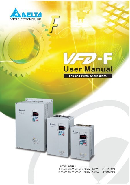
Preface<br />
Thank you for choosing DELTA’s high-performance <strong>VFD</strong>-F Series. <strong>VFD</strong>-F Series are<br />
manufactured by adopting high-quality components, material and incorporating the latest<br />
microprocessor technology available.<br />
DELTA ELECTRONICS, INC. ALL RIGHTS RESERVED<br />
<strong>VFD</strong>-F Series<br />
� Getting Started<br />
This manual will be helpful in the installation, parameter setting, troubleshooting, and daily<br />
maintenance of the AC motor drives. To guarantee safe operation of the equipment, read<br />
the following safety guidelines before connecting power to the AC drives. Keep this<br />
operating manual handy and distribute to all users for reference.<br />
!<br />
WARNING<br />
! Always read this manual thoroughly before using <strong>VFD</strong>-F series AC Motor Drives.<br />
! Ensure that <strong>VFD</strong>-F is grounded in a correct way before putting it into use.<br />
! DANGER! AC input power must be disconnected before any maintenance. Do not connect<br />
or disconnect wires and connectors while power is applied to the circuit. Maintenance must<br />
be performed by qualified technicians.<br />
! CAUTION! There are highly sensitive MOS components on the printed circuit boards.<br />
These components are especially sensitive to static electricity. To avoid damage to these<br />
components, do not touch these components or the circuit boards with metal objects or<br />
your bare hands.<br />
! DANGER! A charge may still remain in the DC-link capacitor with hazardous voltages even<br />
if the power has been turned off. To avoid personal injury, do not remove the cover of the<br />
AC drive until all “DISPLAY LED” lights on the digital keypad are off. Please note that there<br />
are live components exposed within the AC drive. Do not touch these live parts.<br />
! CAUTION! Ground the <strong>VFD</strong>-F using the ground terminal. The grounding method must<br />
comply with the laws of the country where the AC drive is to be installed. Refer to Basic<br />
Wiring Diagram.<br />
! DANGER! The AC drive may be destroyed beyond repair if incorrect cables are connected<br />
to the input/output terminals. Never connect the AC drive output terminals U/T1, V/T2, and<br />
W/T3 directly to the AC main circuit power supply.<br />
! CAUTION! The final enclosures of the AC drive must comply with EN50178. (Live parts<br />
shall be arranged in enclosures or located behind barriers that meet at least the<br />
requirements of the Protective Type IP20. The top surface of the enclosures or barrier that<br />
is easily accessible shall meet at least the requirements of the Protective Type IP40).<br />
(<strong>VFD</strong>-F series corresponds with this regulation.)<br />
! CAUTION! The rated voltage for the AC motor drive must be ≤ 240V for 230V models (≤<br />
480V for 460V models) and the mains supply current capacity must be ≤ 5000A RMS<br />
(≤10000A RMS for the ≥ 40hp (30kW) models)<br />
CAUTION! Heat sink may heat up over 70 o C (158 o F), during the operation. Do not touch<br />
the heat sink.
<strong>VFD</strong>-F Series<br />
TABLE OF CONTENTS<br />
CHAPTER 1 RECEIVING AND INSPECTIONS<br />
1.1 Nameplate Information ........................................................................ 1 - 1<br />
1.2 Model Explanation ............................................................................... 1 - 1<br />
1.3 Serial Number Explanation.................................................................. 1 - 2<br />
CHAPTER 2 STORAGE AND INSTALLATION<br />
2.1 Storage................................................................................................. 2 - 1<br />
2.2 Installation............................................................................................ 2 - 2<br />
CHAPTER 3 WIRING<br />
3.1 Basic Wiring Diagram .......................................................................... 3 - 2<br />
3.2 External Wiring .................................................................................... 3 - 5<br />
3.3 Main Circuit Connection ...................................................................... 3 - 6<br />
3.4 Control Terminals................................................................................. 3 - 9<br />
3.5 Specifications for Power Terminals and Control Terminals ................. 3-11<br />
3.6 Wiring Notes ........................................................................................ 3-14<br />
3.7 Motor Operation Precautions .............................................................. 3-16<br />
CHAPTER 4 DIGITAL KEYPAD OPERATION<br />
4.1 <strong>VFD</strong>-PU01 ........................................................................................... 4 - 2<br />
4.1.1 Description of the Digital Keypad <strong>VFD</strong>-PU01 ............................... 4 - 2<br />
4.1.2 Explanation of Display Message................................................... 4 - 2<br />
4.1.3 Operation Steps of the Digital Keypad <strong>VFD</strong>-PU01 ....................... 4 - 4<br />
DELTA ELECTRONICS, INC. ALL RIGHTS RESERVED
DELTA ELECTRONICS, INC. ALL RIGHTS RESERVED<br />
<strong>VFD</strong>-F Series<br />
4.2 KPF-CC01 ........................................................................................... 4 - 5<br />
4.2.1 Description of the Digital Keypad KPF-CC01 ............................... 4 - 5<br />
4.2.2 Explanation of Display Message................................................... 4 - 5<br />
4.2.3 KPF-CC01 Operation Flow Chart ................................................. 4 - 6<br />
CHAPTER 5 DESCRIPTION OF PARAMETER SETTINGS<br />
5.1 Group 0: AC Drive Status Parameters................................................. 5 - 1<br />
5.2 Group 1: Basic Parameters ................................................................. 5 - 4<br />
5.3 Group 2: Operation Method Parameters............................................. 5 - 9<br />
5.4 Group 3: Output Function Parameters ................................................ 5-15<br />
5.5 Group 4: Input Function Parameters................................................... 5-19<br />
5.6 Group 5: Multi-step Speed Frequency Parameters............................. 5-24<br />
5.7 Group 6: Protection Parameters.......................................................... 5-30<br />
5.8 Group 7: AC Drive and Motor Parameters .......................................... 5-36<br />
5.9 Group 8: Special Parameters .............................................................. 5-39<br />
5.10 Group 9: Communication Parameters............................................... 5-45<br />
5.11 Group 10: PID Control Parameters ................................................... 5-60<br />
5.12 Group 11: Fan and Pump Control Parameters.................................. 5-63<br />
CHAPTER 6 MAINTENANCE AND INSPECTIONS<br />
6.1 Periodic Inspection .............................................................................. 6 - 1<br />
6.2 Periodic Maintenance .......................................................................... 6 - 1<br />
CHAPTER 7 TROUBLESHOOTING AND FAULT INFORMATION........... 7 - 1
<strong>VFD</strong>-F Series<br />
CHAPTER 8 SUMMARY OF PARAMETER SETTINGS ............................ 8 - 1<br />
APPENDIX A SPECIFICATIONS ................................................................ A - 1<br />
APPENDIX B ACCESSORIES<br />
B.1 All Brake Resistors & Brake Units Used in AC Motor Drives.............. B - 1<br />
B.1.1 Dimensions and Weights for Brake Resistors.............................. B - 3<br />
B.1.2 Specifications for Brake Unit ........................................................ B - 5<br />
B.1.3 Dimensions for Brake Unit............................................................ B - 6<br />
B.2 AMD-EMI Filter Cross Reference........................................................ B - 8<br />
B.3 AC Reactor .......................................................................................... B-10<br />
B.3.1 AC Input Reactor Recommended Value ...................................... B-10<br />
B.3.2 AC Output Reactor Recommended Value.................................... B-11<br />
B.4 Non-fuse Circuit Breaker Chart........................................................... B-12<br />
B.5 Fuse Specification Chart ..................................................................... B-13<br />
B.6 PU06.................................................................................................... B-14<br />
B.6.1 Description of the Digital Keypad <strong>VFD</strong>-PU06............................... B-14<br />
B.6.2 Explanation of Display Message .................................................. B-14<br />
B.6.3 PU06 Operation Flow Chart ......................................................... B-15<br />
B.7 Relay Card .......................................................................................... B-16<br />
B.8 Zero Phase Reactor ............................................................................ B-18<br />
APPENDIX C DIMENSIONS........................................................................ C - 1<br />
DELTA ELECTRONICS, INC. ALL RIGHTS RESERVED
CHAPTER 1 RECEIVING AND INSPECTION<br />
DELTA ELECTRONICS, INC. ALL RIGHTS RESERVED 1-1<br />
<strong>VFD</strong>-F Series<br />
This <strong>VFD</strong>-F AC drive has gone through rigorous quality control tests at the factory before<br />
shipment. After receiving the AC drive, please check for the following:<br />
Receiving<br />
� Check to make sure that the package includes an AC drive, the User Manual, dust<br />
covers and rubber bushings.<br />
� Inspect the unit to insure it was not damaged during shipment.<br />
� Make sure that the part number indicated on the nameplate corresponds with the part<br />
number of your order.<br />
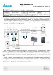
1.1 Nameplate Information: Example for 7.5HP/5.5kW 3-phase 460V AC drive<br />
AC Drive Model<br />
Input Spec.<br />
Output Spec.<br />
Output Frequency Range<br />
Enclosure type<br />
Serial Number & Bar Code<br />
1.2 Model Explanation<br />
<strong>VFD</strong> 055 F 43 A<br />
Series<br />
Name<br />
007: 1.0HP(0.75kW)<br />
015: 2.0HP(1.5kW)<br />
022: 3.0HP(2.2kW)<br />
037: 5.0HP(3.7kW)<br />
055: 7.5HP(5.5kW)<br />
075: 10 HP(7.5kW)<br />
110: 15 HP(11kW)<br />
MODEL : <strong>VFD</strong>055F43A<br />
INPUT : 3PH 380-480V 50/60Hz 14A<br />
OUTPUT : 3PH 0-480V 13 A 9.9KVA<br />
7.5HP<br />
Frequency Range : 1.5-120Hz<br />
Enclosure: TYPE 1<br />
055F43AT201001<br />
DELTA ELECTRONICS INC.<br />
Version Type<br />
Input Voltage<br />
23:Three phase 230V<br />
43:Three phase 460V<br />
MADE IN XXXXX<br />
<strong>VFD</strong>-F Series<br />
Applicable motor capacity<br />
150: 20HP(15kW) 750: 100HP(75kW)<br />
900: 120HP(90kW)<br />
220: 30 HP(22kW)<br />
300: 40HP(30kW)<br />
1100: 150HP(110kW)<br />
1320: 175HP(130kW)<br />
370: 50HP(37kW)<br />
450: 60HP(45kW)<br />
550: 75HP(55kW)<br />
1600: 215HP(160kW)<br />
1850: 250HP(185kW)<br />
2200: 300HP(220kW)<br />
1
<strong>VFD</strong>-F Series<br />
1.3 Series Number Explanation<br />
055F43A<br />
3<br />
460V 3-PHASE 7.5HP(5.5kW)<br />
1-2<br />
Production number<br />
Production model<br />
If there is any nameplate information not corresponding to your purchase order or any<br />
problem, please contact your distributor.<br />
DELTA ELECTRONICS, INC. ALL RIGHTS RESERVED<br />
1
CHAPTER 2 STORAGE AND INSTALLATION<br />
2.1 Storage<br />
DELTA ELECTRONICS, INC. ALL RIGHTS RESERVED 2-1<br />
<strong>VFD</strong>-F Series<br />
The AC drive should be kept in the shipping carton before installation. In order to retain the<br />
warranty coverage, the AC drive should be stored properly when it is not to be used for an<br />
extended period of time.<br />
Ambient Conditions:<br />
Operation Air Temperature: -10 o C to +40 o C (14 o F to 104 o F)<br />
+50 o C (122 o F) without dust cover.<br />
Atmosphere pressure: 86 to 106 kPa<br />
Installation Site Altitude: below 1000m<br />
Vibration: Maximum 9.80 m/s 2 (1G) at less than 20Hz<br />
Maximum 5.88 m/s 2 (0.6G) at 20Hz to 50Hz<br />
Storage<br />
Temperature: -20 o C to +60 o C (-4 o F to 140 o F)<br />
Relative Humidity: Less than 90%, no condensation allowed<br />
Atmosphere pressure: 86 to 106 kPa<br />
Transportation Temperature: -20 o C to +60 o C (-4 o F to 140 o F)<br />
Relative Humidity: Less than 90%, no condensation allowed<br />
Atmosphere pressure: 86 to 106 kPa<br />
Vibration: Maximum 9.86 m/s 2 (1G) at less than 20Hz, Maximum 5.88<br />
m/s 2 (0.6G) at 20Hz to 50Hz<br />
Pollution Degree 2: good for a factory type environment.<br />
2
<strong>VFD</strong>-F Series<br />
2.2 Installation<br />
CAUTION<br />
The control, power supply and motor leads must be laid separately. They must not be<br />
fed through the same cable conduit / trunking.<br />
High voltage insulation test equipment must not be used on cables connected to the<br />
drive.<br />
Improper installation of the AC drive will greatly reduce its life. Be sure to observe the<br />
following precautions when selecting a mounting location.<br />
Failure to observe these precautions may void the warranty!<br />
� Do not mount the AC drive near heat-radiating elements or in direct sunlight.<br />
� Do not install the AC drive in a place subjected to high temperature, high humidity,<br />
excessive vibration, corrosive gases or liquids, or airborne dust or metallic particles.<br />
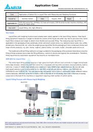
� Mount the AC drive vertically and do not restrict the air flow to the heat sink fins.<br />
� The AC drive generates heat. Allow sufficient space around the unit for heat dissipation.<br />
50mm<br />
150mm<br />
<strong>VFD</strong>-F<br />
F<br />
H<br />
U<br />
<strong>VFD</strong>-PU01<br />
RUNSTOP<br />
JO G<br />
FWD REV<br />
JOG<br />
STOP<br />
RUN RESET<br />
150mm<br />
50mm<br />
2-2<br />
Air Flow<br />
DELTA ELECTRONICS, INC. ALL RIGHTS RESERVED
CHAPTER 3 WIRING<br />
DANGER<br />
Hazardous Voltage<br />
Before accessing the AC drive:<br />
� Disconnect all power to the AC drive.<br />
� Wait five minutes for DC bus capacitors discharge.<br />
DELTA ELECTRONICS, INC. ALL RIGHTS RESERVED 3-1<br />
<strong>VFD</strong>-F Series<br />
Any electrical or mechanical modification to this equipment without prior written<br />
consent of <strong>Delta</strong> <strong>Electronics</strong>, Inc. will void all warranties and may result in a safety<br />
hazard in addition to voiding the UL listing.<br />
Short Circuit Withstand:<br />
The rated voltage for the AC motor drive must be ≤ 240V for 230V models (≤<br />
480V for 460V models) and the mains supply current capacity must be ≤<br />
5000A RMS (≤10000A RMS for the ≥ 40hp (30kW) models)<br />
3
<strong>VFD</strong>-F Series<br />
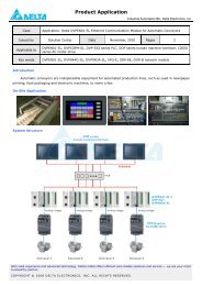
3.1 Basic Wiring Diagram<br />
Users must connect wires according to the following circuit diagram shown below. Do not<br />
plug a Modem or telephone line to the RS-485 communication port, permanent damage may<br />
result. Pins 1 & 2 are the power sources for the optional copy keypad and should not be<br />
used while using RS-485 communication.<br />
For 230V series, 1~15HP models<br />
460V series, 1~20HP models<br />
3-2<br />
Brake Resistor<br />
(Optional)<br />
R<br />
NFB<br />
+1 +2/B1<br />
R(L1)<br />
B2 -<br />
U(T1)<br />
Motor<br />
S<br />
T<br />
NFB<br />
SA<br />
S(L2)<br />
T(L3)<br />
E<br />
V(T2)<br />
W(T3)<br />
M<br />
3~<br />
Recommended circuit<br />
MC<br />
when power supply is<br />
turned OFF by a fault<br />
output.<br />
ON<br />
If the fault occurs, the OFF<br />
contact will be ON to turn<br />
MC<br />
off the power and protect the power system.<br />
Factory Setting:<br />
FWD/STOP<br />
Sink Mode<br />
REV/STOP<br />
Source<br />
E.F.<br />
Sw1<br />
Multi-step 1<br />
Sink<br />
Multi-step 2<br />
Please refer to the following Multi-step 3<br />
wiring for Sink mode and<br />
Source mode.<br />
Multi-step 4<br />
Factory<br />
RESET<br />
Setting JOG<br />
Accel/Decel Prohibit<br />
1/2 Accel/Decel Switch<br />
NOTE<br />
Digital Signal Common<br />
Don't apply the mains voltage<br />
directly to above terminals.<br />
SW2<br />
E<br />
RB<br />
RC<br />
RA1 Multi-function indication<br />
output contacts<br />
RB1 240VAC 2.5A<br />
120VAC 5A<br />
RC1<br />
24V<br />
28VDC 5A<br />
Factory setting: no function<br />
FWD<br />
RA2<br />
REV<br />
RB2 Factory setting:<br />
no function<br />
EF<br />
RC2<br />
MI1<br />
Multi-function analog output terminals<br />
MI2<br />
AFM1<br />
Factory setting: output frequency<br />
MI3<br />
0~10Vdc/2mA<br />
AFM2<br />
Factory setting: output current<br />
MI4 Multi-<br />
0~20mA/4~20mA<br />
MI5 function<br />
Max. Impedance: 500Ω<br />
Input<br />
ACM<br />
Analog Signal Common<br />
MI6 Terminals<br />
MI7<br />
E<br />
MI8<br />
RY00 RA3 Optional<br />
DCM<br />
RC3<br />
E<br />
RA4<br />
RC4<br />
+10V<br />
Power Supply<br />
RA5<br />
0-5V 0-10V<br />
5k<br />
3<br />
2<br />
1<br />
4~20mA<br />
4~20mA<br />
+10V 20mA<br />
AVI<br />
Master Frequency<br />
0~10V (47k )<br />
ACI1<br />
ACI2<br />
RC5<br />
RA6<br />
RC6<br />
RA7<br />
RC7<br />
ACM<br />
RA8<br />
Analog Signal Common RC8<br />
1:+EV<br />
Relay B.D.<br />
2:GND<br />
*RS-485<br />
3:SG-<br />
Serial Communication<br />
4:SG+ Interface<br />
5:NC<br />
Main circuit (power) terminals<br />
Control circuit terminals<br />
6:NC<br />
Shielded leads&cable<br />
DELTA ELECTRONICS, INC. ALL RIGHTS RESERVED
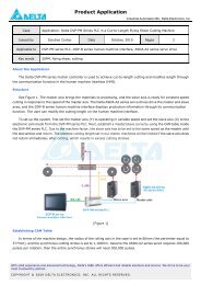
For 230V series, 20HP and above models<br />
460V series, 25HP and above models<br />
DELTA ELECTRONICS, INC. ALL RIGHTS RESERVED 3-3<br />
Brake Unit (Optional)<br />
<strong>VFD</strong>B B1<br />
PN B2 Brake Resistor<br />
(Optional)<br />
<strong>VFD</strong>-F Series<br />
R<br />
NFB<br />
+1 +2<br />
R(L1)<br />
-<br />
U(T1)<br />
Motor<br />
S<br />
T<br />
NFB<br />
Recommended circuit<br />
when power supply<br />
is turned OFF by a<br />
SA<br />
MC<br />
S(L2)<br />
T(L3)<br />
E<br />
RB<br />
V(T2)<br />
W(T3)<br />
E<br />
M<br />
3~<br />
fault output.<br />
If the fault occurs, the<br />
ON<br />
contact will be ON to turn<br />
OFF<br />
off the power and protect the power system. MC<br />
Factory setting: Sink Mode FWD/STOP<br />
Source<br />
REV/STOP<br />
Sw1 E.F.<br />
Sink<br />
Multi-step 1<br />
Please refer to the following Multi-step 2<br />
wiring for Sink mode and<br />
Source mode.<br />
Multi-step 3<br />
Multi-step 4<br />
Factory RESET<br />
Setting<br />
JOG<br />
RC<br />
24V<br />
FWD<br />
REV<br />
EF<br />
MI1<br />
MI2<br />
MI3<br />
Multi-<br />
MI4<br />
function<br />
MI5 Input<br />
MI6 Terminals<br />
RA1 Multi-function indication<br />
output contacts<br />
RB1 240VAC 2.5A<br />
120VAC 5A<br />
RC1<br />
28VDC 5A<br />
Factory setting: no function<br />
RA2<br />
RB2 Factory setting:<br />
no function<br />
RC2<br />
Multi-function Analog Output Terminals<br />
AFM1 Factory setting: output frequency<br />
0~10Vdc/2mA<br />
AFM2 Factory setting: output current<br />
0~20mA/4~20mA<br />
Max. Impedance: 500Ω<br />
ACM<br />
Analog Signal Common<br />
Accel/Decel Prohibit<br />
MI7<br />
E<br />
1/2 Accel/Decel Switch<br />
NOTE Digital Signal Common<br />
Don't apply the mains voltage<br />
directly to above terminals.<br />
MI8<br />
DCM<br />
E<br />
RY00 RA3 Optional<br />
RC3<br />
RA4<br />
RC4<br />
SW2<br />
0-5V 0-10V<br />
5k<br />
3<br />
2<br />
1<br />
4~20mA<br />
4~20mA<br />
+10V<br />
Power Supply<br />
+10V 20mA<br />
AVI<br />
Master Frequency<br />
0~10V (47k )<br />
ACI1<br />
ACI2<br />
RA5<br />
RC5<br />
RA6<br />
RC6<br />
RA7<br />
RC7<br />
ACM<br />
RA8<br />
Analog Signal Common RC8<br />
1:+EV<br />
Relay B.D.<br />
2:GND<br />
*RS-485<br />
3:SG-<br />
Serial Communication<br />
4:SG+<br />
Interface<br />
5:NC<br />
Main circuit (power) terminals<br />
Control circuit terminals<br />
6:NC<br />
Shielded leads&cable<br />
3
<strong>VFD</strong>-F Series<br />
Wiring for SINK mode and SOURCE mode<br />
Sink<br />
Sw1<br />
Source<br />
JOG<br />
1/2 Accel/Decel switch<br />
JOG<br />
1/2 Accel/Decel switch<br />
3-4<br />
MI7<br />
MI8<br />
MI7<br />
MI8<br />
DELTA ELECTRONICS, INC. ALL RIGHTS RESERVED
3.2 External Wiring<br />
Power Supply<br />
EMI Filter<br />
R/L1 S/L2 T/L3<br />
U/T1 V/T2 W/T3<br />
Motor<br />
FUSE/NFB<br />
Magnetic<br />
Contactor<br />
Input AC<br />
Line Reactor<br />
Zero-phase<br />
Reactor<br />
E<br />
+/B1<br />
B2<br />
DELTA ELECTRONICS, INC. ALL RIGHTS RESERVED 3-5<br />
-<br />
E<br />
Brake Unit<br />
(Optional)<br />
BR<br />
<strong>VFD</strong>B<br />
BR<br />
Zero-phase<br />
Reactor<br />
Output AC<br />
Line Reactor<br />
Brake Resistor<br />
(Optional)<br />
Power<br />
supply<br />
Items Explanations<br />
Fuse/NFB<br />
(Optional)<br />
Magnetic<br />
contactor<br />
(Optional)<br />
Input AC<br />
Line Reactor<br />
(Optional)<br />
Zero-phase<br />
Reactor<br />
(Ferrite Core<br />
Common<br />
Choke)<br />
(Optional)<br />
EMI filter<br />
(Optional)<br />
Brake<br />
Resistor<br />
(Optional)<br />
Output AC<br />
Line Reactor<br />
(Optional)<br />
Please follow the specific power<br />
supply requirements shown in<br />
Appendix A.<br />
<strong>VFD</strong>-F Series<br />
There may be an inrush current<br />
during power up. Please check the<br />
chart of Appendix B and select the<br />
correct fuse with rated current. Use<br />
of an NFB is optional.<br />
Please do not use a Magnetic<br />
contactor as the I/O switch of the AC<br />
motor drive, as it will reduce the<br />
operating life cycle of the AC drive.<br />
Used to improve the input power<br />
factor, to reduce harmonics and<br />
provide protection from AC line<br />
disturbances (surges, switching<br />
spikes, short interruptions, etc.). AC<br />
line reactor should be installed when<br />
the power supply capacity is 500kVA<br />
or more or advanced capacity is<br />
activated. The wiring distance should<br />
be ≤ 10m. Refer to appendix B for<br />
details.<br />
Zero-phase reactors are used to<br />
reduce radio noise especially when<br />
audio equipment is installed near the<br />
inverter. Effective for noise reduction<br />
on both the input and output sides.<br />
Attenuation quality is good for a wide<br />
range from AM band to 10MHz.<br />
Appendix B specifies the zero-phase<br />
reactor. (RF220X00A)<br />
To reduce electromagnetic<br />
interference, please refer to<br />
Appendix B for more details.<br />
Used to reduce the deceleration time<br />
of the motor. Please refer to the chart<br />
in Appendix B for specific Brake<br />
Resistors.<br />
Motor surge voltage amplitude<br />
depends on motor cable length. For<br />
applications with long motor cable<br />
(>20m), it is necessary to install a<br />
reactor at the inverter output side.<br />
3
<strong>VFD</strong>-F Series<br />
3.3 Main Circuit Connection<br />
Figure 1 for the main circuit terminals<br />
Non-fuse breaker<br />
(NFB)<br />
MC<br />
R<br />
S<br />
T<br />
Figure 2 for the main circuit terminals<br />
R<br />
S<br />
T<br />
Non-fuse breaker<br />
(NFB)<br />
MC<br />
+1 +2/B1 B2 -<br />
R(L1)<br />
U(T1)<br />
S(L2)<br />
V(T2)<br />
T(L3)<br />
W(T3)<br />
E<br />
E<br />
3-6<br />
Brake Resistor<br />
(Optional)<br />
<strong>VFD</strong>B<br />
+1 +2 -<br />
R(L1)<br />
U(T1)<br />
S(L2)<br />
T(L3)<br />
E<br />
V(T2)<br />
W(T3)<br />
E<br />
Motor<br />
IM<br />
3~<br />
Brake Resistor (Optional)<br />
Terminal Explanations<br />
Terminal Symbol Explanation of Terminal Function<br />
R/L1, S/L2, T/L3 AC line input terminals<br />
U/T1, V/T2, W/T3 AC drive output terminals motor connections<br />
+1,+2 Connections for DC Link Reactor (optional)<br />
+2/B1~B2 Connections for Brake Resistor (optional)<br />
+2~ -,+2/B1~ - Connections for External Brake Unit (<strong>VFD</strong>B series)<br />
Earth Ground<br />
Motor<br />
IM<br />
3~<br />
DELTA ELECTRONICS, INC. ALL RIGHTS RESERVED
Mains power terminals (R/L1, S/L2, T/L3)<br />
DELTA ELECTRONICS, INC. ALL RIGHTS RESERVED 3-7<br />
<strong>VFD</strong>-F Series<br />
� Connect these terminals (R/L1, S/L2, T/L3) via a non-fuse breaker or earth leakage<br />
breaker to 3-phase AC power (some models to 1-phase AC power) for circuit protection.<br />
It is unnecessary to consider phase-sequence.<br />
� It is recommended to add a magnetic contactor (MC) in the power input wiring to cut off<br />
power quickly and reduce malfunction when activating the protection function of AC<br />
motor drives. Both ends of the MC should have an R-C surge absorber.<br />
� Please make sure to fasten the screw of the main circuit terminals to prevent sparks<br />
which is made by the loose screws due to vibration.<br />
� Please use voltage and current within the regulation shown in Appendix A.<br />
� When using a general GFCI (Ground Fault Circuit Interrupter), select a current sensor<br />
with sensitivity of 200mA or above, and not less than 0.1-second detection time to avoid<br />
nuisance tripping. For the specific GFCI of the AC motor drive, please select a current<br />
sensor with sensitivity of 30mA or above.<br />
� Do NOT run/stop AC motor drives by turning the power ON/OFF. Run/stop AC motor<br />
drives by RUN/STOP command via control terminals or keypad. If you still need to<br />
run/stop AC drives by turning power ON/OFF, it is recommended to do so only ONCE<br />
per hour.<br />
� Do NOT connect 3-phase models to a 1-phase power source.<br />
Output terminals for main circuit (U, V, W)<br />
� If the AC drive is installed in the place where a load reactor is needed, install the filter<br />
close to U/T1, V/T2, W/T3 side of AC drive. Do not use a Capacitor or L-C Filter<br />
(Inductance-Capacitance) or R-C Filter (Resistance-Capacitance), unless approved by<br />
<strong>Delta</strong>.<br />
� DO NOT connect phase-compensation capacitors or surge absorbers at the output<br />
terminals of AC motor drives.<br />
� Use well-insulated motor, suitable for inverter operation.<br />
Terminals [+1, +2] for connecting DC reactor<br />
DC reactor<br />
Jumper<br />
� To improve power factor and reduce harmonics, connect a DC reactor between<br />
terminals [+1, +2]. Please remove the jumper before connecting the DC reactor.<br />
+1<br />
3
<strong>VFD</strong>-F Series<br />
Terminals [+2/B1, B2] for connecting brake resistor and terminals [+2/B1, -] for<br />
connecting external brake unit<br />
BR<br />
+2/B1 B2<br />
+2/B1<br />
BR<br />
<strong>VFD</strong>B<br />
3-8<br />
-<br />
Brake resistor(optional)<br />
Brake unit(optional)<br />
Refer to Appendix B for the use of<br />
special brake resistor/unit<br />
� Connect a brake resistor or brake unit in applications with frequent deceleration ramps,<br />
short deceleration time, too low brake torque or requiring increased brake torque.<br />
� If the AC motor drive has a built-in brake chopper, connect the external brake resistor to<br />
the terminals [+2/B1, B2].<br />
� Some models of <strong>VFD</strong>-F series don’t have a built-in brake chopper, please connect an<br />
external optional brake unit and brake resistor.<br />
� When not used, please leave the terminals [+2(+2/B1), -] open.<br />
WARNING!<br />
Short-circuiting [B2] or [-] to [+2/B1] can damage the AC motor drive.<br />
DELTA ELECTRONICS, INC. ALL RIGHTS RESERVED
3.4 Control Terminals<br />
Multi-function<br />
Input Terminal<br />
SINK/NPN Mode<br />
+24V<br />
Internal Circuit<br />
DCM<br />
DELTA ELECTRONICS, INC. ALL RIGHTS RESERVED 3-9<br />
Multi-function<br />
Input Terminal<br />
SOURCE/PNP Mode<br />
DCM<br />
+24V<br />
Internal Circuit<br />
<strong>VFD</strong>-F Series<br />
Terminal symbols and functions<br />
Terminal Symbols Terminal Functions Factory Settings<br />
FWD Forward-Stop command<br />
REV Reverse-Stop command<br />
EF External fault<br />
MI1 Multi-function Input 1 Factory setting: Multi-step speed command 1<br />
MI2 Multi-function Input 2 Factory setting: Multi-step speed command 2<br />
MI3 Multi-function Input 3 Factory setting: Multi-step speed command 3<br />
MI4 Multi-function Input 4 Factory setting: Multi-step speed command 4<br />
MI5 Multi-function Input 5 Factory setting: RESET<br />
MI6 Multi-function Input 6 Factory setting: JOG<br />
MI7 Multi-function Input 7 Factory setting: Accel/Decel prohibit<br />
MI8 Multi-function Input 8 Factory setting: Accel/Decel time switch 1<br />
+24V DC Voltage Source (+24V, 20mA), used for source mode.<br />
DCM Digital Signal Common<br />
Used as common for digital inputs and used<br />
for sink mode.<br />
RA 1<br />
Multi-function Relay1<br />
output (N.O.) a<br />
RB 1<br />
Multi-function Relay1<br />
output (N.C.) b<br />
RC 1<br />
RA 2<br />
RB 2<br />
RC 2<br />
Multi-function Relay1<br />
common<br />
Multi-function Relay2<br />
output (N.O.) a<br />
Multi-function Relay2<br />
output (N.C.) b<br />
Multi-function Relay2<br />
common<br />
1.5A(N.O.)/1A(N.C.) 240VAC<br />
1.5A(N.O.)/1A(N.C.) 24VDC<br />
Refer to Pr.03-00 to Pr.03-01<br />
3
<strong>VFD</strong>-F Series<br />
Terminal Symbols Terminal Functions Factory Settings<br />
+10V<br />
Potentiometer power<br />
source<br />
+10V 20mA<br />
AVI Analog voltage Input<br />
0 to +10V correspond to Max. operation<br />
frequency<br />
ACI 1/2 Analog current Input<br />
4 to 20mA correspond to Max. operation<br />
frequency<br />
AFM 1<br />
AFM 2<br />
ACM<br />
Analog frequency<br />
/current meter 1<br />
Analog frequency<br />
/current meter 2<br />
Analog control signal<br />
(common)<br />
* Control signal wiring size: 18 AWG (0.75 mm 2 ).<br />
0 to 10V correspond to Max. operation<br />
frequency<br />
4 to 20mA correspond to 2 times of output<br />
current<br />
Analog input terminals (ACI1, ACI2, ACM)<br />
� Analog input signals are easily affected by external noise. Use shielded wiring and keep<br />
it as short as possible (
DELTA ELECTRONICS, INC. ALL RIGHTS RESERVED 3-11<br />
<strong>VFD</strong>-F Series<br />
3.5 Specifications for Power Terminals and Control Terminals<br />
Frame B<br />
Power Terminals:<br />
R/L1, S/L2, T/L3, U/T1, V/T2, W/T3, , +1, +2/B1, -, B2<br />
Models<br />
<strong>VFD</strong>007F23A<br />
<strong>VFD</strong>007F43A<br />
<strong>VFD</strong>007F43H<br />
<strong>VFD</strong>015F23A<br />
Wire Gauge Torque Wire Type<br />
Frame C<br />
+1 +2 B1 - B2<br />
R/L1 S/L2 T/L3<br />
POWER<br />
U/T1 V/T2 W/T3<br />
Screw Torque :<br />
18Kgf-cm<br />
Wire Gauge :<br />
18~10AWG<br />
IM MOTOR<br />
3<br />
<strong>VFD</strong>015F43A<br />
<strong>VFD</strong>015F43H<br />
<strong>VFD</strong>022F23A<br />
<strong>VFD</strong>022F43A<br />
<strong>VFD</strong>022F43H<br />
<strong>VFD</strong>037F23A<br />
<strong>VFD</strong>037F43A<br />
<strong>VFD</strong>037F43H<br />
12-24 AWG.<br />
(3.3-0.2mm 2 )<br />
18kgf-cm<br />
(15.6in-lbf)<br />
Control Terminals:<br />
Wire Gauge Torque<br />
12-24AWG. (3.3-0.2mm 2 ) 4kgf-cm (3in-lbf)<br />
Stranded<br />
Copper only,<br />
75℃<br />
Power Terminals:<br />
R/L1, S/L2, T/L3, U/T1, V/T2, W/T3, , +1, +2/B1, -, B2<br />
Models<br />
<strong>VFD</strong>055F23A<br />
<strong>VFD</strong>055F43B<br />
<strong>VFD</strong>055F43H<br />
<strong>VFD</strong>075F23A<br />
Wire Gauge Torque Wire Type<br />
<strong>VFD</strong>075F43B<br />
<strong>VFD</strong>075F43H<br />
<strong>VFD</strong>110F23A<br />
<strong>VFD</strong>110F43A<br />
<strong>VFD</strong>110F43H<br />
<strong>VFD</strong>150F43A<br />
<strong>VFD</strong>150F43H<br />
12-8 AWG.<br />
(3.3-8.4mm 2 )<br />
30kgf-cm<br />
(26in-lbf)<br />
Stranded<br />
Copper only,<br />
75℃<br />
NOTE<br />
If wiring of the terminal utilizes the wire with a diameter of<br />
6AWG.(13.3mm 2 ), it is thus necessary to use the Recognized<br />
Ring Terminal to conduct a proper wiring.<br />
Control Terminals:<br />
Wire Gauge Torque<br />
12-24AWG. (3.3-0.2mm 2 ) 4kgf-cm (3in-lbf)<br />
3
Frame D<br />
Frame E<br />
<strong>VFD</strong>-F Series<br />
3 IM<br />
POWER ( ) ( - )<br />
+ DC DC MOTOR<br />
POWER<br />
CHARGE<br />
IM MOTOR<br />
3<br />
Power Terminals:<br />
R/L1, S/L2, T/L3, U/T1, V/T2, W/T3, , +1, +2, -,<br />
Models<br />
<strong>VFD</strong>150F23A<br />
<strong>VFD</strong>185F23A<br />
<strong>VFD</strong>185F43A<br />
Wire Gauge Torque Wire Type<br />
<strong>VFD</strong>185F43H<br />
<strong>VFD</strong>220F23A<br />
<strong>VFD</strong>220F43A<br />
<strong>VFD</strong>220F43H<br />
<strong>VFD</strong>300F43A<br />
<strong>VFD</strong>300F43H<br />
8-2 AWG.<br />
(8.4-33.6mm 2 )<br />
30kgf-cm<br />
(26in-lbf)<br />
Stranded<br />
Copper only,<br />
75℃<br />
NOTE<br />
If wiring of the terminal utilizes the wire with a diameter of<br />
1AWG.(42.4mm 2 ), it is thus necessary to use the Recognized<br />
Ring Terminal to conduct a proper wiring.<br />
Control Terminals:<br />
Wire Gauge Torque<br />
12-24AWG. (3.3-0.2mm 2 ) 4kgf-cm (3in-lbf)<br />
Power Terminals:<br />
R/L1, S/L2, T/L3, U/T1, V/T2, W/T3, , +1, +2, -,<br />
Models Wire Gauge Torque Wire Type<br />
<strong>VFD</strong>300F23A 1/0-4/0 AWG.<br />
(53.5-107.2mm 2 )<br />
<strong>VFD</strong>370F23A<br />
<strong>VFD</strong>750F43A<br />
<strong>VFD</strong>750F43H<br />
3/0-4/0 AWG.<br />
(85-107.2mm 2 )<br />
<strong>VFD</strong>900F43C 4/0 AWG.<br />
<strong>VFD</strong>900F43H (107.2mm 2 200kgf-cm<br />
(173in-lbf)<br />
<strong>VFD</strong>370F43A<br />
<strong>VFD</strong>370F43H<br />
)<br />
3 AWG. (26.7mm 2 )<br />
<strong>VFD</strong>450F43A<br />
<strong>VFD</strong>450F43H<br />
2 AWG. (33.6mm 2 57kgf-cm<br />
)<br />
(49.5in-lbf)<br />
<strong>VFD</strong>550F43A 1/0-4/0 AWG.<br />
<strong>VFD</strong>550F43H (53.5-107.2mm 2 Stranded<br />
Copper only,<br />
75℃<br />
200kgf-cm<br />
) (173in-lbf)<br />
Control Terminals:<br />
Wire Gauge Torque<br />
12-24AWG. (3.3-0.2mm 2 ) 4kgf-cm (3in-lbf)<br />
3-12<br />
DELTA ELECTRONICS, INC. ALL RIGHTS RESERVED
Frame G<br />
R/L1 S/L2 T/L3 +1 +2 U/T1 V/T2 W/T3<br />
POWER DC(+) DC(-) IM<br />
3 MOTOR<br />
Frame H<br />
R/L1 S/L2 T/L3 + - U/T1 V/T2 W/T3<br />
POWER DC ( + ) DC ( -)<br />
DELTA ELECTRONICS, INC. ALL RIGHTS RESERVED 3-13<br />
<strong>VFD</strong>-F Series<br />
Power Terminals:<br />
R/L1, S/L2, T/L3, U/T1, V/T2, W/T3, , +1, +2, -,<br />
Models<br />
<strong>VFD</strong>1100F43C<br />
Wire Gauge Torque Wire Type<br />
<strong>VFD</strong>1100F43H<br />
<strong>VFD</strong>1320F43A<br />
<strong>VFD</strong>1320F43H<br />
<strong>VFD</strong>1600F43A<br />
<strong>VFD</strong>1600F43H<br />
4/0 AWG. - 300MCM<br />
(107.2-152mm 2 )<br />
300kgf-cm<br />
(260in-lbf)<br />
Stranded<br />
Copper only,<br />
75℃<br />
NOTE<br />
It needs following additional terminal when wiring, and add<br />
insulation sheath on position where following figure shows.<br />
70MAX.<br />
16 +0<br />
-4<br />
31MAX.<br />
8.2MIN.<br />
26.5MAX.<br />
Control Terminals:<br />
Wire Gauge Torque<br />
12-24AWG. (3.3-0.2mm 2 )<br />
Power Terminals:<br />
4kgf-cm (3in-lbf)<br />
R/L1, S/L2, T/L3, U/T1, V/T2, W/T3, , +1, -,<br />
Models Wire Gauge Torque Wire Type<br />
<strong>VFD</strong>1850F43A<br />
<strong>VFD</strong>1850F43H<br />
<strong>VFD</strong>2200F43A<br />
<strong>VFD</strong>2200F43H<br />
500 MCM (max)<br />
408kgf-cm<br />
(354 in-lbf)<br />
Stranded<br />
copper only,<br />
75°C<br />
NOTE<br />
It needs following additional terminal when wiring, and add<br />
insulation sheath on position where following figure shows.<br />
12.2(MIN.)<br />
42.0(MAX.)<br />
INSULATION SHEATH<br />
42.0(MAX.)<br />
WIRE<br />
Control Terminals:<br />
Wire Gauge Torque<br />
12-24AWG. (3.3-0.2mm 2 ) 4kgf-cm (3in-lbf)<br />
23.0(MAX.)<br />
80.0(MAX.)<br />
3
<strong>VFD</strong>-F Series<br />
3.6 Wiring Notes: PLEASE READ PRIOR TO INSTALLATION.<br />
1. ! CAUTION: Do not connect the AC power to the U/T1, V/T2, W/T3 terminals, as it<br />
will damage the AC drive.<br />
2. ! WARNING: Ensure all screws are tightened to the proper torque rating.<br />
3. During installation, follow all local electrical, construction, and safety codes for the<br />
country the drive is to be installed in.<br />
4. Ensure that the appropriate protective devices (circuit breaker or fuses) are connected<br />
between the power supply and AC drive.<br />
5. Make sure that the leads are connected correctly and the AC drive is properly grounded.<br />
(Ground resistance should not exceed 0.1Ω.)<br />
6. Use ground leads that comply with AWG/MCM standards and keep them as short as<br />
possible.<br />
7. Multiple <strong>VFD</strong>-F units can be installed in one location. All the units should be grounded<br />
directly to a common ground terminal. The <strong>VFD</strong>-F ground terminals may also be<br />
connected in parallel, as shown in the figure below. Ensure there are no ground loops.<br />
3-14<br />
Forward<br />
running<br />
8. When the AC drive output terminals U/T1, V/T2, and W/T3 are connected to the motor<br />
terminals U, V, and W, respectively, the motor will rotate counterclockwise (as viewed<br />
from the shaft ends of the motor) when a forward operation command is received. To<br />
reverse the direction of motor rotation, switch over any of the two motor leads.<br />
9. Make sure that the power source is capable of supplying the correct voltage and<br />
required current to the AC drive.<br />
10. Do not attach or remove wiring when power is applied to the AC drive.<br />
11. Do not inspect components unless inside “CHARGE” lamp is turned off.<br />
12. Do not monitor the signals on the circuit board while the AC drive is in operation.<br />
DELTA ELECTRONICS, INC. ALL RIGHTS RESERVED
DELTA ELECTRONICS, INC. ALL RIGHTS RESERVED 3-15<br />
<strong>VFD</strong>-F Series<br />
13. For the single-phase rated AC drives, the AC power can be connected to any two of the<br />
three input terminals R/L1, S/L2, T/L3. Note: This drive is not intended for the use<br />
with single-phase motors.<br />
14. Route the power and control wires separately, or at 90°angle to each other.<br />
15. If a filter is required for reducing EMI (Electro Magnetic Interference), install it as close<br />
as possible to AC drive. EMI can also be reduced by lowering the Carrier Frequency.<br />
16. If the AC drive is installed in the place where a load reactor is needed, install the filter<br />
close to U/T1, V/T2, W/T3, side of AC drive. Do not use a Capacitor or L-C Filter<br />
(Inductance-Capacitance) or R-C Filter (Resistance-Capacitance), unless approved by<br />
<strong>Delta</strong>.<br />
17. When using a general GFCI (Ground Fault Circuit Interrupter), select a current sensor<br />
with sensitivity of 200mA or above, and not less than 0.1-second detection time to avoid<br />
nuisance tripping. For the specific GFCI of the AC motor drive, please select a current<br />
sensor with sensitivity of 30mA or above.<br />
18. To improve the input power factor, to reduce harmonics and provide protection from AC<br />
line disturbances (surges, switching spikes, short interruptions, etc.), AC line reactor<br />
should be installed when the power supply capacity is 500kVA or more.<br />
19. There are highly sensitive MOS components on the printed circuit boards. These<br />
components are especially sensitive to static electricity. To prevent damage to these<br />
components, do not touch these components or the circuit boards with metal objects or<br />
your bare hands.<br />
3
<strong>VFD</strong>-F Series<br />
3.7 Motor Operation Precautions<br />
1. When using the AC drive to operate a standard 3-phase induction motor, notice that the<br />
energy loss is greater than for an inverter duty motor.<br />
2. Avoid running a standard induction motor at low speed. Under these conditions, the<br />
motor temperature may rise above the motor rating due to limited airflow produced by<br />
the motor’s fan.<br />
3. When the standard motor operates at low speed, the output load must be decreased.<br />
4. If 100% output torque is desired at low speed, it may be necessary to use a special<br />
“inverter-duty” rated motor.<br />
3-16<br />
DELTA ELECTRONICS, INC. ALL RIGHTS RESERVED
CHAPTER 4 DIGITAL KEYPAD OPERATION<br />
DELTA ELECTRONICS, INC. ALL RIGHTS RESERVED 4-1<br />
<strong>VFD</strong>-F Series<br />
This chapter describes the various controls and indicators found on the digital keypad. The<br />
information in this chapter should be read and understood before performing the start–up<br />
procedures described in the chapter of parameter settings.<br />
� Description of the Keypad<br />
� Description of Display<br />
� Keypad Operation Modes & Programming Steps<br />
4
<strong>VFD</strong>-F Series<br />
4.1 <strong>VFD</strong>-PU01<br />
4.1.1 Description of the Digital Keypad <strong>VFD</strong>-PU01<br />
JOG<br />
By pressing JOG key.<br />
Initiates jog operation.<br />
Left key<br />
moves cursor to the left<br />
UP and DOWN Key<br />
Sets the parameter<br />
number and changes the<br />
numerical data, such as<br />
Master Frequency.<br />
F<br />
H<br />
U<br />
JOG<br />
<strong>VFD</strong>-PU01<br />
STOP<br />
RUN RESET<br />
4.1.2 Explanation of Display Message<br />
4-2<br />
LED Display<br />
Display frequency, current, voltage<br />
and error, etc.<br />
Part Number<br />
Status Display<br />
Display the driver's current status<br />
MODE<br />
Changes between different<br />
display mode.<br />
STOP/RESET<br />
RUN key<br />
Display Message Descriptions<br />
Display the AC drive Master Frequency.<br />
Display the actual operation frequency present at terminals<br />
U/T1, V/T2, and W/T3.<br />
Display voltage (V), Current (A), power factor and feedback<br />
signal (P)<br />
Display the output current present at terminals U/T1, V/T2,<br />
and W/T3.<br />
DELTA ELECTRONICS, INC. ALL RIGHTS RESERVED
Display Message Descriptions<br />
DELTA ELECTRONICS, INC. ALL RIGHTS RESERVED 4-3<br />
Display the AC drive forward run status.<br />
The AC drive reverse run status.<br />
Display the specified parameter setting.<br />
Display the actual value stored within the specified<br />
parameter.<br />
External Fault.<br />
<strong>VFD</strong>-F Series<br />
Display “End” for approximately 1 second if input has been<br />
accepted. After a parameter value has been set, the new<br />
value is automatically stored in memory. To modify an entry,<br />
use the or keys.<br />
Display “Err”, if the input is invalid.<br />
4
<strong>VFD</strong>-F Series<br />
4.1.3 Operation steps of the Digital Keypad <strong>VFD</strong>-PU01<br />
START<br />
F<br />
H<br />
U<br />
F<br />
H<br />
U<br />
Selecting mode<br />
Setting parameters<br />
MODE<br />
MODE<br />
NOTE: In the parameter setting mode, you can press MODE to return the selecting mode.<br />
To shift data<br />
START<br />
To modify data<br />
Setting direction<br />
or<br />
F<br />
H<br />
U<br />
F<br />
H<br />
U<br />
F<br />
H<br />
U<br />
F<br />
H<br />
U<br />
4-4<br />
MODE<br />
Note: In the selection mode, press to set the parameters.<br />
F<br />
H<br />
U<br />
F<br />
H<br />
U<br />
F<br />
H<br />
U<br />
START<br />
MODE<br />
F<br />
H<br />
U<br />
F<br />
H<br />
U<br />
F<br />
H<br />
U<br />
or<br />
move to previous display<br />
F<br />
H<br />
U<br />
F<br />
H<br />
U<br />
F<br />
H<br />
U<br />
F<br />
H<br />
U<br />
MODE<br />
F<br />
H<br />
U<br />
F<br />
H<br />
U<br />
Success to set parameter.<br />
F<br />
H<br />
U<br />
Input data error<br />
F<br />
H<br />
U<br />
F<br />
H<br />
U<br />
MODE<br />
GO START<br />
DELTA ELECTRONICS, INC. ALL RIGHTS RESERVED
4.2 KPF-CC01<br />
DELTA ELECTRONICS, INC. ALL RIGHTS RESERVED 4-5<br />
<strong>VFD</strong>-F Series<br />
For models of <strong>VFD</strong>-F (HVAC) series<br />
<strong>VFD</strong>007F43H; <strong>VFD</strong>015F43H; <strong>VFD</strong>022F43H; <strong>VFD</strong>037F43H; <strong>VFD</strong>055F43H; <strong>VFD</strong>075F43H;<br />
<strong>VFD</strong>110F43H; <strong>VFD</strong>150F43H; <strong>VFD</strong>185F43H; <strong>VFD</strong>220F43H; <strong>VFD</strong>300F43H; <strong>VFD</strong>370F43H;<br />
<strong>VFD</strong>450F43H; <strong>VFD</strong>550F43H; <strong>VFD</strong>750F43H; <strong>VFD</strong>900F43H; <strong>VFD</strong>1100F43H; <strong>VFD</strong>1320F43H;<br />
<strong>VFD</strong>1600F43H; <strong>VFD</strong>1850F43H; <strong>VFD</strong>2200F43H<br />
NOTE<br />
When KPF-CC01 is connected on AC motor drive, the communication protocol is forced to be 9600, 8,<br />
N, 2. After KPF-CC01 is disconnected, and AC motor drive immediately gets connection with other<br />
controller by RS-485, 1st communication fault may occur due to different communication protocol. AC<br />
motor drive will automatically reset communication protocol as previous parameter setting from 2nd<br />
communication.<br />
4.2.1 Description of the Digital Keypad KPF-CC01<br />
JOG Operation key<br />
Press this key to execute<br />
the JOG frequency operation.<br />
Left key<br />
Moves the cursor left.<br />
UP and DOWN key<br />
Set the parameter number and<br />
changes the numerical data, such<br />
as Master Frequency.<br />
FWD/REV Direction key<br />
Select FWD/REV operation<br />
RUN key<br />
Start AC drive operation.<br />
4.2.2 Explanation of Display Message<br />
Display Message Description<br />
LCD Display<br />
Indicates frequency, voltage, current, user<br />
defined units, read, and save etc.<br />
Model Number<br />
Status Display<br />
Display the driver's current status.<br />
MODE<br />
Change between different display mode.<br />
Parameter Unit key<br />
Switch the operation command source.<br />
Right key<br />
Moves the cursor right.<br />
PROG/DATA<br />
Used to enter programming parameters.<br />
STOP/RESET<br />
Stops AC drive operation or reset the drive<br />
after fault occurred.<br />
The AC motor drive Master Frequency Command.<br />
The Actual Operation Frequency present at terminals U, V, W.<br />
4
<strong>VFD</strong>-F Series<br />
Display Message Description<br />
The output current present at terminals U, V, W.<br />
The specified group description.<br />
The specified parameter description and setting<br />
Copy Mode: Press MODE key for about 2~3 seconds in main<br />
page. Use UP/DOWN key to select copy function (Read, Write,<br />
Delete) and LEFT/RIGHT key to select memory address. Total<br />
two blocks are available.<br />
Use UP/DOWN key to confirm copy function. Press PROG/DATA<br />
key to execute.<br />
External Fault.<br />
Input data is accepted.<br />
Input data is invalid.<br />
4.2.3 KPF-CC01 Operation Flow Chart<br />
KPF-CC01 Operation Flow Chart<br />
4-6<br />
DELTA ELECTRONICS, INC. ALL RIGHTS RESERVED
CHAPTER 5 DESCRIPTION OF PARAMETER SETTINGS<br />
�: This parameter can be set during operation.<br />
5.1 Group 0: AC Drive Status Parameters<br />
� Group 0 is read-only.<br />
DELTA ELECTRONICS, INC. ALL RIGHTS RESERVED 5-1<br />
<strong>VFD</strong>-F Series<br />
00 - 00 Software Version Factory setting: Read Only<br />
� This parameter displays the software version of AC drive.<br />
00 - 01 AC Drive Status Indication 1 Factory setting: Read Only<br />
� This parameter displays the AC drive status.<br />
Code AC Drive Status Explanation<br />
00 No fault occurred<br />
01 oc over current<br />
02 ov over voltage<br />
03 oH over temperature<br />
04 oL overload<br />
05 oL1 electronic thermal relay<br />
06 EF (external fault) EF-DCM is closed<br />
07 occ (AC drive IGBT fault ) IGBT short circuit protection<br />
08 cF3 (CPU failure) Abnormal A/D reading during self-check<br />
09 HPF (hardware protection failure) Hardware protection function activated during<br />
self-check.<br />
10 ocA (over current during acceleration) Output current exceeds protection level during<br />
acceleration<br />
11 ocd (over current during deceleration) Output current exceeds protection level during<br />
deceleration<br />
12 ocn (over current during steady state Output current exceeds protection level during<br />
operation)<br />
steady state operation.<br />
13 GFF (ground fault) Ground fault protection feature activated<br />
14 Lv (under voltage) Low input voltage<br />
15 cF1 EEPROM input data is abnormal<br />
16 cF2 EEPROM output data is abnormal<br />
17 bb (base block) BB is set and activated<br />
18 oL2 (motor over load 2) Output current exceeds rated motor current<br />
19 Reserved<br />
20 codE software or password protection<br />
21 EF1 (external emergency stop) EF1 (a multifunction-DCM is enabled)<br />
22 PHL (phase loss) Input power lacks phase.<br />
3-phase input power is unbalance and exceeds<br />
specification.<br />
23 Lc (Low Current) Low current detection during operation.<br />
24 FbL(Feedback Loss) Feedback signal is abnormal.<br />
25 Reserved<br />
5
<strong>VFD</strong>-F Series<br />
Code AC Drive Status Explanation<br />
26 FAnP Fan Power Fault<br />
27 FF1 Fan 1 Fault<br />
28 FF2 Fan 2 Fault<br />
29 FF3 Fan 3 Fault<br />
30 FF123 Fan 1, 2, 3 Fault<br />
31 FF12 Fan 1, 2 Fault<br />
32 FF13 Fan 1, 3 Fault<br />
33 FF23 Fan 2, 3 Fault<br />
34 Fv Gate Drive Low Voltage Protect<br />
00 - 02 AC Drive Status Indication 2 Factory setting: Read Only<br />
Display Bit 0~1: 00: Run LED is off and STOP led is on. (AC Drive stopping)<br />
01: Run LED is blink and STOP led is on. (AC Drive deceleration to stop)<br />
10: Run LED is on and STOP led is blink. (AC Drive standby)<br />
11: Run LED is on and STOP led is off. (AC Drive running)<br />
Bit 2: 1: Jog on.<br />
Bit 3~4: 00: Rev LED is off and FWD led is on. (Forward)<br />
01: Rev LED is blink and FWD led is on. (Reverse to Forward)<br />
10: Rev LED is on and FWD led is blink. (Forward to Reverse)<br />
11: Rev LED is on and FWD led is off. (Reverse)<br />
Bit 5-7: Reserved<br />
Bit 8: Master frequency source via communication interface<br />
Bit 9: Master frequency source via analog<br />
Bit10: Running command via communication interface<br />
Bit11: Parameter locked<br />
Bit12~15: Reserved<br />
00 - 03 Frequency Setting Factory setting: Read Only<br />
� This parameter displays the frequency command set by the user.<br />
00 - 04 Output Frequency Factory setting: Read Only<br />
� This parameter displays actual output frequency of the AC drive.<br />
00 - 05 Output Current Factory setting: Read Only<br />
� This parameter displays actual output current of the AC drive.<br />
00 - 06 DC-BUS Voltage Factory setting: Read Only<br />
� This parameter displays DC-BUS voltage of the AC drive.<br />
00 - 07 Output Voltage Factory setting: Read Only<br />
� This parameter displays output voltage of the AC drive.<br />
5-2<br />
DELTA ELECTRONICS, INC. ALL RIGHTS RESERVED
<strong>VFD</strong>-F Series<br />
00 - 08 Output Power Factor Factory setting: Read Only<br />
� This parameter displays output power factor.<br />
00 - 09 Output Power (kW) Factory setting: Read Only<br />
� This parameter displays output power of the AC drive.<br />
00 - 10 Feedback Signal Actual Value Factory setting: Read Only<br />
� This parameter displays feedback signal value.<br />
00 - 11 Feedback Signal (%) Factory setting: Read Only<br />
� This parameter displays feedback signal value (%).<br />
00 - 12 User Target Value (Low bit) uL 0-99.99 Factory setting: Read Only<br />
00 - 13 User Target Value (High bit) uH 0-9999 Factory setting: Read Only<br />
� User Target Value = Actual output frequency (0-04) × User Defined Multiplier (02-10).<br />
� Maximum summed display of both parameters is 999999.99.<br />
� When User Target Value
<strong>VFD</strong>-F Series<br />
5.2 Group 1: Basic Parameters<br />
01 - 00 Maximum Output Frequency Factory Setting: 60.00<br />
Settings 50.00~120.00Hz<br />
� This parameter determines the AC drives maximum output frequency. All master frequency<br />
commands set by the keypad or analog inputs are limited by this parameter. The analog commands<br />
(AVI, ACI1 and ACI2) may be scaled to correspond to the output frequency range. (Please refer to<br />
04-09~04-20.)<br />
01 - 01 Maximum Voltage Frequency (Base Frequency) Factory Setting: 60.00<br />
Settings 0.10~120.00 Hz<br />
� This parameter sets the frequency, where the maximum output voltage (Pr. 01-02) will be reached.<br />
The output frequency may exceed this setting, but the output voltage doesn’t increase beyond this<br />
point. This parameter should be set according to the rated frequency of the motor as indicated on the<br />
motor nameplate.<br />
� If this parameter setting is smaller than the rated frequency of the motor, nuisance over current faults<br />
or damage to the AC drive may occur.<br />
� If this parameter setting is greater than the rated frequency of the motor, the motor will encounter<br />
torque loss.<br />
01 - 02 Maximum Output Voltage Factory Setting: 220.0/440.0<br />
Settings 230V series: 0.1 ~ 255.0V<br />
460V series: 0.2 ~ 510.0V<br />
� This parameter determines the Maximum Output Voltage of the AC drive. This parameter setting<br />
should be set according to rated voltage of the motor as indicated on the motor nameplate. If rated<br />
voltage of the motor is 440V, this parameter must be set to 440V. If rated voltage of the motor is 380V,<br />
this parameter must be set to 380V.<br />
� If this setting is greater than the rated voltage of the motor, nuisance over current faults or damage to<br />
the AC drive may occur.<br />
01 - 03 Mid-point Frequency Factory Setting: 1.50<br />
Settings 0.10~120.00 Hz<br />
� This parameter sets the Mid-point Frequency of the V/f curve.<br />
� This parameter must meet the following argument. Pr.1-01 >= Pr.1-03 >= Pr.1-05.<br />
5-4<br />
DELTA ELECTRONICS, INC. ALL RIGHTS RESERVED
DELTA ELECTRONICS, INC. ALL RIGHTS RESERVED 5-5<br />
<strong>VFD</strong>-F Series<br />
01 - 04 Mid-point Voltage Factory Setting: 5.5/11.0<br />
Settings 230V series: 0.1 ~ 255.0V<br />
460V series: 0.2 ~ 510.0V<br />
� This parameter sets the Mid-point Voltage of the V/f curve.<br />
� This parameter must meet the following argument. Pr.1-02 >= Pr.1-04 >= Pr.1-06.<br />
01 - 05 Minimum Output Frequency Factory Setting: 1.50<br />
Settings 0.10~20.00 Hz<br />
� This parameter sets the Minimum Output Frequency of the AC drive. This parameter must be lower<br />
than or equal to the Mid-point frequency<br />
01 - 06 Minimum Output Voltage Factory Setting: 5.5/11.0<br />
Settings 230V series: 0.1 ~ 50.0V<br />
460V series: 0.2 ~100.0V<br />
� This parameter sets the Minimum Output Voltage of the AC Drive. The parameter must be lower<br />
than or equal to the Mid-point Voltage.<br />
01 - 07 Upper Bound Frequency Factory Setting: 60.00<br />
Settings 0.00~120.00 Hz<br />
� This parameter will limit the maximum output frequency of AC drive. If slip compensation<br />
(Pr.07-02~07-05) or feedback control (Pr.10-00~10-09) are enabled, the output frequency of AC<br />
drive may exceed the Master Frequency Command, but it will continue to be limited by this<br />
parameter setting.<br />
01 - 08 Lower Bound Frequency Factory Setting: 0.00<br />
Settings 0.00~120.00 Hz<br />
� This parameter will limit the minimum output frequency. Any Master Frequency Command below<br />
Pr.1-08 will result in an output equal to Pr.1-08.<br />
� Upon a start command, the drive will accelerate from Pr.1-05 Minimum Output Frequency to the<br />
Master Frequency Command point.<br />
� The Lower Bound Frequency setting must be smaller than the Dwell Frequency (Pr.11-08>=01-08).<br />
If lower bound frequency setting is greater than the Dwell Frequency, the AC drive will equalize the<br />
two settings to the Lower Bound point.<br />
5
<strong>VFD</strong>-F Series<br />
Output voltage<br />
01-02<br />
01-04<br />
01-06<br />
01-05 01-08 01-03 01-01<br />
01-00 01-07<br />
5-6<br />
Output Frequency<br />
01 - 09 Acceleration Time 1 � Factory Setting: 10.0/60.0<br />
01 - 10 Deceleration Time 1 �<br />
01 - 11 Acceleration Time 2 �<br />
Factory Setting: 10.0/60.0<br />
Factory Setting: 10.0/60.0<br />
01 - 12 Deceleration Time 2 � Factory Setting: 10.0/60.0<br />
01 - 13 Acceleration Time 3 � Factory Setting: 10.0/60.0<br />
01 - 14 Deceleration Time 3 � Factory Setting: 10.0/60.0<br />
01 - 15 Acceleration Time 4 � Factory Setting: 10.0/60.0<br />
01 - 16 Deceleration Time 4 � Factory Setting: 10.0/60.0<br />
01 - 17 JOG Acceleration Time � Factory Setting: 10.0/60.0<br />
01 - 18 JOG Deceleration Time � Factory Setting: 10.0/60.0<br />
Settings 0.1~3600.0 Sec Unit: 0.1sec<br />
� Acceleration time is the time required for the AC drive to ramp from 0 Hz to its Maximum Output<br />
Frequency (Pr.1-00). Deceleration time is the time required for the AC drive to decelerate from<br />
Maximum Output Frequency (Pr.1-00) down to 0 Hz.<br />
� An Acceleration or Deceleration time that is too quick, may cause the AC drives protection features<br />
to enable (over-current stall prevention during Accel 06-01 or over-voltage stall prevention 06-00).<br />
If this occurs, the actual Accel/Decel time will be longer than this setting.<br />
� Warning: An acceleration or deceleration that is too quick, may cause excess loads on the AC drive<br />
and may permanently damage the drive.<br />
� If you want to decelerate the AC drive in short time period, we recommend to add an external brake<br />
module and brake resistor.<br />
� You can set 1 st to 4 th Accel/Decel time via multi-function input terminals 04-00 to 04-07.<br />
DELTA ELECTRONICS, INC. ALL RIGHTS RESERVED
DELTA ELECTRONICS, INC. ALL RIGHTS RESERVED 5-7<br />
<strong>VFD</strong>-F Series<br />
01 - 19 JOG Frequency � Factory Setting: 6.00<br />
Settings 0.0 Hz~120.00 Hz Unit: 0.1sec<br />
� When the JOG function is to be utilized, users need to use the multi-function input terminals (Pr.<br />
04-00 to 04-07 set to 07) or the JOG key on keypad. Once a JOG command is initiated, the AC drive<br />
will accelerate from the Minimum Output Frequency (Pr.01-05) to the JOG frequency (Pr.01-19).<br />
� The accel/decel time of the JOG operation is determined by the JOG accel/decel speed (Pr.01-17 and<br />
01-18).<br />
� When the drive is in operation, the JOG command is disabled.<br />
01 - 20 S Curve Delay Time in Accel Factory Setting: 0.00<br />
01 - 21 S Curve Delay Time in Decel<br />
Settings 0.00~2.50sec<br />
� These parameters enable the S curve. The longer the S curve time period the smoother the transition<br />
between speeds.<br />
01 - 22 Modulation Index � Factory Setting: 1.00<br />
Settings 0.90~1.20 Unit: 0.1<br />
� This parameter sets the ratio of the Maximum Output Voltage to the input voltage.<br />
� The Maximum Output Voltage (Pr.01-02) is normally limited to the input voltage. With the<br />
Modulation Index parameter, the user is able to increase the output voltage beyond the incoming line<br />
voltage.<br />
� A Modulation Index of 1, defines the Maximum Output Voltage (Pr. 1-02) is equal to the input<br />
voltage.<br />
� A Modulation index of 1.2, defines the Maximum Output Voltage (Pr. 1-02) is 20% higher than in the<br />
input voltage. Please note, the output voltage wave form will be distorted due to harmonics and may<br />
increase torque ripple and noise in the motor.<br />
5
<strong>VFD</strong>-F Series<br />
01 - 23 Accel/Decel Time Unit<br />
Settings 00: Unit is 1 Sec<br />
01: Unit is 0.1 Sec<br />
02: Unit is 0.01 Sec<br />
� This parameter sets the resolution of accel/decel time (Pr.01-09 to 01-18).<br />
� A high resolution decreases the accel/decel time range as shown in the following chart.<br />
01-23 Accel/Decel time unit Accel/Decel time range<br />
00 1 Sec 1~36000 Sec<br />
01 0.1 Sec 0.1~3600.0 Sec<br />
02 0.01 Sec 0.01~360.00 Sec<br />
5-8<br />
Factory Setting: 01<br />
DELTA ELECTRONICS, INC. ALL RIGHTS RESERVED
5.3 Group 2: Operation Method Parameters<br />
DELTA ELECTRONICS, INC. ALL RIGHTS RESERVED 5-9<br />
<strong>VFD</strong>-F Series<br />
02 - 00 Source of Frequency Command � Factory Setting: 00<br />
Settings 00: via keypad<br />
01: via analog input AVI<br />
02: via analog input ACI1<br />
03: via analog input ACI2<br />
04: via RS485 serial communication<br />
05: via External Reference<br />
Settings:<br />
00: Frequency command source is the keypad. User may use UP/DOWN keys to adjust the<br />
frequency command. Also if the Multi-Function Input terminals (Pr.04-00 to 04-07) are set to<br />
13 or 14, their function will be the same as the UP/DOWN keys.<br />
01: Frequency command source is the analog input terminal AVI.<br />
02: Frequency command source is the analog input terminal ACI1.<br />
03: Frequency command source is the analog input terminal ACI2.<br />
04: Frequency command source is the RS485 serial communication.<br />
05: Frequency command source depends on the setting of Pr. 04-24.<br />
� You may use SW2 on the control board to choose between a 0~10V or 0~5V input range. When AVI<br />
is set to 0~5V, the voltage input is limited to 5V maximum. The relationship to frequency is 0V = 0<br />
Hz and 5V = Pr1-00.<br />
02 - 01 Source of Operation Command � Factory Setting: 00<br />
Settings 00: Controlled by the digital keypad<br />
01: Controlled by the external terminals, keypad STOP enabled.<br />
02: Controlled by the external terminals, keypad STOP disabled.<br />
03: Controlled by the RS-485 communication interface, keypad STOP enabled.<br />
04: Controlled by the RS-485 communication interface, keypad STOP<br />
disabled.<br />
� This parameter sets the operation command source of the AC drive.<br />
� When the AC drive is controlled by an external source, you may select 2-wire or 3-wire operation.<br />
Please refer to Pr.02-05.<br />
5
<strong>VFD</strong>-F Series<br />
02 - 02 Stop Method<br />
5-10<br />
Factory Setting: 00<br />
Settings 00:Stop = ramp to stop, E.F. (External Fault) = coast to stop<br />
01:Stop = coast to stop, E.F. = coast to stop<br />
02:Stop = ramp to stop, E.F. = ramp to stop<br />
03:Stop = coast to stop, E.F. = ramp to stop<br />
� Ramp: The AC drive decelerates the motor to minimum output frequency according to the<br />
deceleration time setting.<br />
� Coast: The AC drive output instantly stops upon command and the motor free spins until it comes to<br />
a complete stop.<br />
� External Fault may be enabled by the EF terminal or a Multi-Function terminal. Please refer to<br />
Pr.04-00 to 04-07.<br />
� Loss of an ACI signal may cause an E.F condition. Please refer to 02-07.<br />
Output<br />
Frequency<br />
Motor<br />
speed<br />
Frequency<br />
Operation<br />
Command RUN<br />
Stops according<br />
to deceleration<br />
time<br />
STOP<br />
Output<br />
Frequency<br />
Motor<br />
Speed<br />
Time<br />
Frequency<br />
Free running<br />
Operation<br />
to stop<br />
Command RUN STOP<br />
Ramp Coast<br />
02 - 03 PWM Carrier Frequency Selections � Unit: 1<br />
Time<br />
Settings 1~10HP 4000~10000Hz Factory Setting: 9000Hz<br />
15~30HP 3000~9000Hz Factory Setting: 6000Hz<br />
≧40HP 2000~6000Hz Factory Setting: 4000Hz<br />
� This parameter sets the carrier frequency of PWM output. The factory setting and setting range<br />
depend on the model type.<br />
� When the temperature of the heat sink is greater than its limit, the AC drive will automatic lower the<br />
carrier frequency to avoid over heating the AC drive.<br />
DELTA ELECTRONICS, INC. ALL RIGHTS RESERVED
DELTA ELECTRONICS, INC. ALL RIGHTS RESERVED 5-11<br />
<strong>VFD</strong>-F Series<br />
� The Carrier frequency of the PWM output has a signification influence on the electromagnetic noise,<br />
heat dissipation of the AC drive, and the acoustic noise to the motor as shown in the following chart.<br />
Carrier<br />
frequency<br />
Signification<br />
Acoustic<br />
Noise<br />
Minimal<br />
Electromagnetic<br />
Noise<br />
Signification<br />
Leakage<br />
Current<br />
Signification<br />
Heat<br />
Dissipation<br />
Signification<br />
Minimal Signification Minimal Minimal Minimal<br />
� When the carrier frequency is low, current ripple of the AC drive is large. This may result in a current<br />
display value greater than the actual value.<br />
02 - 04 Forward/Reverse Enable<br />
Settings 00: Forward/Reverse enabled<br />
01: Reverse disabled<br />
02: Forward disabled<br />
� This parameter enables the direction of the AC drive.<br />
02 - 05 2-wire/3-wire Operation Control Modes<br />
Settings 00: 2-wire (#1), FWD/STOP, REV/STOP<br />
01: 2-wire (#2), RUN/STOP, REV/FWD<br />
02: 3-wire<br />
� This parameter sets the operation mode when operating by external terminals.<br />
� Please refer to 02-01.<br />
02-05 External Terminal<br />
00 (2-wire #1)<br />
FWD / STOP<br />
REV / STOP<br />
01 (2-wire #2)<br />
RUN / STOP<br />
REV / FWD<br />
02 3-wire<br />
FWD/STOP<br />
REV/STOP<br />
RUN/STOP<br />
FWD/REV<br />
FWD:("OPEN":STOP)<br />
("CLOSE":FWD)<br />
REV: ("OPEN":STOP)<br />
("CLOSE":REV)<br />
DCM<br />
FWD:("OPEN":STOP)<br />
("CLOSE":RUN)<br />
REV :("OPEN":FWD)<br />
("CLOSE":REV)<br />
DCM<br />
STOP<br />
RUN<br />
FWD<br />
("CLOSE":RUN)<br />
EF ("OPEN":STOP)<br />
FWD/REV<br />
REV ("OPEN":FWD)<br />
("CLOSE":REV)<br />
DCM<br />
<strong>VFD</strong>-F<br />
Factory Setting: 00<br />
Factory Setting: 00<br />
5
<strong>VFD</strong>-F Series<br />
02 - 06 Line Start Lockout<br />
5-12<br />
Factory Setting: 01<br />
Settings 00: Enabled<br />
01: Disabled<br />
02: If the command to run still remains after<br />
resetting, the inverter will continue to run.<br />
� When enabled, the AC drive will not start when powered up with a run command applied. The AC<br />
drive must see the run command transition from stop to run after power up. When Line Start<br />
Lockout is disabled (also known as Auto-Start), the AC drive will start when powered-up with run<br />
commands applied.<br />
� Pr02-06=2:<br />
This determines the following matter. The <strong>VFD</strong> (Variable-Frequency Drive) detects an error message and<br />
eliminates the error. If the command terminal remains running in the external function terminals, you can<br />
simply press the RESET button to make the <strong>VFD</strong> running again.<br />
02 - 07 ACI(4~20mA)Loss of ACI Signal<br />
Settings 00: Decelerate to 0Hz<br />
01: E.F.<br />
02: Continue operation by the last frequency command<br />
03: Use loss of ACI Signal Frequency of Pr02-16<br />
� This parameter determines the AC drives response to a loss of the ACI input.<br />
Factory Setting: 01<br />
02 - 08 Start-up Display Selection � Factory Setting: 00<br />
Settings Bit0~1: 00 = F LED<br />
01 = H LED<br />
10 = U LED (special display)<br />
11 = Fwd / Rev<br />
Bit2: 0 = Fwd LED / 1 = Rev LED<br />
Bit3~5: 000 = 1st 7-step<br />
001 = 2nd 7-step<br />
010 = 3rd 7-step<br />
011 = 4th 7-step<br />
100 = 5th 7-step<br />
Bit6~7: Reserved<br />
� This parameter determines the display on keypad after each power up.<br />
DELTA ELECTRONICS, INC. ALL RIGHTS RESERVED
DELTA ELECTRONICS, INC. ALL RIGHTS RESERVED 5-13<br />
<strong>VFD</strong>-F Series<br />
� To program this parameter the user must first generate a Hex value with the information above. Then<br />
using the Hex to Decimal conversion to find the corresponding Decimal value and enter it into this<br />
parameter.<br />
� For example, a setting of 21 (decimal 21= hex 010101) will display the “H” and “REV” LEDs and<br />
the cursor will stay at the 3rd 7-step display upon power up.<br />
� When setting to U LED, please refer to 02-09.<br />
02 - 09 Special Display � Factory Setting: 00<br />
Settings 00: A displays output current of AC drive<br />
01: U displays DC-Bus voltage of AC drive<br />
02: E displays RMS of output voltage<br />
03: P displays feedback signal<br />
04: PLC display auto procedure state<br />
05: T displays heat sink’s temperature<br />
06: The keypad’s screen displays both target value and feedback value<br />
controlled by PID (Proportional–Integral–Derivative controller (PID<br />
controller)).<br />
� This parameter chooses the display on the keypad immediately following the “U” user defined<br />
setting.<br />
� “MODE” key will scroll from “F”, “H”, “U”, (Pr. 02-09), FWD, and back to “F”.<br />
� Users may also use the “LEFT” key on the digital keypad to switch display content.<br />
� When Pr02-09 is set to be 6, the keypad’s screen displays both target value and feedback value<br />
controlled by PID as shown below.<br />
F<br />
H<br />
U<br />
0.0 0.0<br />
Target 目標值 Value Feedback 回授值 Value<br />
5
<strong>VFD</strong>-F Series<br />
02 - 10 User Defined Coefficient � Factory Setting: 1.00<br />
Settings 0.01~160.00 Unit: 0.01<br />
� When this parameter is set, the “H “display value = actual output frequency of AC drive x 02-10.<br />
� If output frequency of AC drive is 90Hz, set 02-10 to 2.5. When H LED lights, the value on the<br />
display is 225.00.<br />
02 - 11 Flying Start � Factory Setting: 00<br />
Settings 00: Disable<br />
01: Enable (DC brake disabled)<br />
� When the AC drive starts into a running motor (Flying Start), it may cause an over current on the<br />
drive and may damage the motor. Using speed search upon start-up will allow the drive to slowly<br />
find the motor speed, smoothly take control of the motor, and bring it to command speed.<br />
� If the Flying Start feature is enabled upon start-up, the DC brake 08-01 will be disabled.<br />
02 - 12 Flying Start Frequency � Factory Setting: 00<br />
Settings 00: Begin search from Master Frequency Command<br />
01: Begin search from Maximum Frequency (Pr.01-00)<br />
02 - 13 Master Frequency Memory Setting � Factory Setting: 01<br />
Settings 00: Do not remember the last known frequency<br />
01: Remember the last known frequency<br />
� If this parameter is set to 00: The AC drive will not store the last known master frequency command,<br />
after power is removed.<br />
� If this parameter is set to 01: The AC drive will memorize the last known master frequency<br />
command after power off. Upon power up the last known frequency is displayed.<br />
� After a fault, the AC drive will always remember the last know master frequency command.<br />
� This feature is only enabled when Pr. 02-00 is set for 0 or 4.<br />
5-14<br />
DELTA ELECTRONICS, INC. ALL RIGHTS RESERVED
DELTA ELECTRONICS, INC. ALL RIGHTS RESERVED 5-15<br />
<strong>VFD</strong>-F Series<br />
02-14 Source of Second Frequency Command � Factory<br />
Setting<br />
00<br />
Setting<br />
Range<br />
Master Frequency Setting is controlled by PID<br />
00<br />
controller.<br />
Master frequency is controlled by an external terminal via analog input<br />
01<br />
AVI: DC 0~+10V.<br />
Master frequency is controlled by an external terminal via analog input<br />
02<br />
ACI1: DC 4~ 20mA.<br />
Master frequency is controlled by an external terminal via analog input<br />
03<br />
ACI2: DC 4~ 20mA<br />
Master frequency is handled via RS485 serial<br />
04<br />
communication (RJ-11).<br />
05 External Reference Master frequency via External Reference.<br />
� This parameter sets the source of inverter’s second frequency.<br />
02-15 Source of Second Operation Command � Factory Setting 00<br />
Setting<br />
Range<br />
00 Controlled by the digital keypad<br />
01 Controlled by the external terminals, keypad STOP enabled.<br />
02 Controlled by the external terminals, keypad STOP disabled<br />
Controlled by the RS-485 communication interface keypad STOP<br />
03<br />
enabled.<br />
Controlled by the RS-485 communication interface keypad STOP<br />
04<br />
disabled.<br />
� This parameter sets the source of inverter’s second operation command.<br />
02-16 Loss of ACI Signal � Factory Setting 0.00<br />
Setting<br />
Range<br />
0.00-Highest operational frequency<br />
� This parameter sets the loss of ACI signal<br />
5
<strong>VFD</strong>-F Series<br />
5.4 Group 3: Output Function Parameters<br />
03 - 00 Multi-function Output terminal 1 (Relay 1)<br />
03 - 01 Multi-function Output terminal 2 (Relay 2)<br />
03 - 02 Multi-function Output terminal 3 (Relay 3)<br />
03 - 03 Multi-function Output terminal 4 (Relay 4)<br />
03 - 04 Multi-function Output terminal 5 (Relay 5)<br />
03 - 05 Multi-function Output terminal 6 (Relay 6)<br />
03 - 06 Multi-function Output terminal 7 (Relay 7)<br />
03 - 07 Multi-function Output terminal 8 (Relay 8)<br />
Setting Range 00-43<br />
Setting Functions Descriptions<br />
00 No function<br />
01 Motor No. 1<br />
02 Motor No. 2<br />
03 Motor No. 3<br />
04 Motor No. 4<br />
05 Motor No. 5<br />
06 Motor No. 6<br />
07 Motor No. 7<br />
08 Motor No. 8<br />
09 Auxiliary 1 output<br />
10 Auxiliary 2 output<br />
11 Auxiliary 3 output<br />
12 Auxiliary 4 output<br />
13 Auxiliary 5 output<br />
14 Auxiliary 6 output<br />
15 Auxiliary 7 output<br />
5-16<br />
Factory Setting: 00<br />
Factory Setting: 00<br />
Factory Setting: 00<br />
Factory Setting: 00<br />
Factory Setting: 00<br />
Factory Setting: 00<br />
Factory Setting: 00<br />
Factory Setting: 00<br />
All unused terminals should be set to 00, to assure<br />
they have no effect on derive operation.<br />
When starting circulative control, AC drive will<br />
automatic set this parameter by 11-01 ~ 11-03. If<br />
there is only one motor available to operate while<br />
running circulative control, the circulative control<br />
will stop. That means the motor will not be<br />
switched.<br />
Parameter value 20 to 26 program Multi-Function<br />
Input Terminals (Pr.04-00~Pr.04-07) to correspond<br />
with the AC drive multi-function output terminals<br />
Pr.03-00 to 03-07 (settings 09-15).<br />
16 Indication during operation The corresponding output will be closed during<br />
operation (including DC brake time).<br />
17 Master frequency<br />
The corresponding output will be closed when<br />
attained<br />
output frequency reaches master frequency<br />
command.<br />
18 Zero Speed (including shutdown) The corresponding output will be closed when the<br />
AC drive has no output voltage signal.<br />
19 Over-torque The corresponding output relay will be closed when<br />
the AC drives output current exceeds the<br />
over-torque detection level 06-04.<br />
20 External Fault The corresponding output will be closed when the<br />
EF is enabled. (Pr. 4-00 to 4-07)<br />
DELTA ELECTRONICS, INC. ALL RIGHTS RESERVED
Setting Functions Descriptions<br />
DELTA ELECTRONICS, INC. ALL RIGHTS RESERVED 5-17<br />
<strong>VFD</strong>-F Series<br />
21 Low voltage detection The corresponding output will be closed when the<br />
DC Bus voltage drops below our threshold. The<br />
keypad will display “Lu”.<br />
22 Operation Mode indication The corresponding output will be closed when the<br />
AC drives “Operation Command” is controlled by<br />
the external terminals.<br />
23 Fault Indication The corresponding output will be closed when AC<br />
drive has experienced a fault.<br />
24 Master Frequency Attained 1 The corresponding output will be closed when the<br />
AC drives output frequency exceeds (Pr.03-08)<br />
Master Frequency Attained 1.<br />
25 Master Frequency Attained 2 The corresponding output will be closed when the<br />
AC drives output frequency exceeds (Pr.03-09)<br />
Master Frequency Attained 2.<br />
26 Over Temperature indication The corresponding output will be closed when the<br />
AC drive temperature exceeds its rating.<br />
27 Drive Ready The corresponding output will be closed the when<br />
the AC drive is ready and has no faults.<br />
28 External Emergency Stop (EF1) The corresponding output will be closed when<br />
multi-function input terminals (Pr.04-00 to 04-07)<br />
are set to emergency stop and then activated.<br />
29 Software brake output The corresponding output will be closed when the<br />
AC drives DC bus voltage exceeds (Pr.08-19) the<br />
brake level.<br />
30 OL or OL1 overload warning The corresponding output will be closed upon an<br />
overload (OL or OL1) fault.<br />
31 Dwell indication (sleep) The corresponding output will be closed when the<br />
AC drive is in a Dwell status (Pr.11-07).<br />
32 Low current indication The corresponding output will be closed when the<br />
AC drives output current is lower than the Low<br />
Current setting (Pr.06-08).<br />
33 PID feedback error indication The corresponding output will be closed when the<br />
PID feedback signal has an error.<br />
34 PLC Program Running<br />
The Output will be activated when PLC Program is<br />
35 PLC Program Step Completed<br />
36 PLC Program Completed<br />
37 PLC Operation Paused<br />
38 Loss of an ACI signal Indication<br />
39 HOA-Hand mode indication<br />
running.<br />
The Output will be activated for 0.5 sec when each<br />
multi-step speed is attained.<br />
The output will be activated for 0.5 sec when the<br />
PLC program cycle has completed<br />
The output will be activated when PLC operation is<br />
paused.<br />
When there is a loss of an ACI signal indication, the<br />
corresponding relay output will be closed.<br />
Under the Hand mode indication of HOA mode, the<br />
corresponding relay output will be closed.<br />
5
<strong>VFD</strong>-F Series<br />
Setting Functions Descriptions<br />
40 HOA-Off mode indication<br />
Under the Off mode indication of HOA mode, the<br />
corresponding relay output will be closed.<br />
Under the Automatic mode indication of HOA<br />
41 HOA-Auto mode indication<br />
mode, the corresponding relay output will be<br />
closed.<br />
42 Fire mode indication<br />
When Fire mode indication is activated, the<br />
corresponding relay output will be closed.<br />
43 Bypass fire mode indication<br />
Under the Bypass fire mode indication, the<br />
corresponding relay output will be closed.<br />
� The <strong>VFD</strong>-F has two form C relays (multi-function output 1 and 2). There is an optional External<br />
Relay Card with 6 NO contact relays (multi-function outputs 3-8).<br />
� External relay specifications = 8A/250VAC or 5A/30VDC.<br />
� Relay delay time is 5~10 msec.<br />
03 - 08 Master Frequency Attained 1<br />
03 - 09 Master Frequency Attained 2<br />
5-18<br />
Factory Setting: 0.00<br />
Settings 0.00~120.00 Hz Unit: 0.01<br />
� An output relay may be programmed to activate when the output frequency exceeds the desired<br />
attained frequency setting of these two parameters.<br />
� There is a � 2Hz window of operation. If the master frequency attained is 20Hz and the output<br />
frequency exceeds 20Hz, the corresponding output relay will be “closed”. When the output<br />
frequency is less than 18Hz, the corresponding output relay will be “opened” as the following<br />
diagram shows.<br />
Master frequency<br />
2 attained<br />
Master frequency<br />
1 attained<br />
Master frequency<br />
attained<br />
Frequency<br />
2Hz<br />
2Hz<br />
2Hz<br />
4Hz<br />
Master<br />
frequency 1<br />
Frequency<br />
command<br />
Master<br />
frequency 2<br />
Time<br />
Output frequency<br />
DELTA ELECTRONICS, INC. ALL RIGHTS RESERVED
03 - 10 Analog Output 1, (AFM1) 0~10Vdc<br />
03 - 11 Analog Output 2, (AFM2) 0/4~ 20mA<br />
Settings 00: Output frequency<br />
01: Output current<br />
02: Output voltage<br />
03: Frequency command<br />
04: Power factor loading<br />
� These parameters select the content of the analog output signals AFM1 and AFM2.<br />
� Setting 00: 0-10V = 0 - (Pr.01-00)<br />
� Setting 01: 0-10V = 0 - (2.52.0 x rated current)<br />
� Setting 02: 0-10V = 0 - (Pr.01-02)<br />
� Setting 03: 0-10V = 0 - Master Freq. command<br />
� Setting 04: 0-10V = 0.0 - output power factor 1.0<br />
� When using 0-20mA output, please refer to Pr. 3-14.<br />
DELTA ELECTRONICS, INC. ALL RIGHTS RESERVED 5-19<br />
<strong>VFD</strong>-F Series<br />
Factory Setting: 00<br />
Factory Setting: 01<br />
� Maximum impedance loading of analog output 2 (AFM2) can’t be greater than 500 ohms.<br />
03 - 12 Analog Output Gain 1 � Factory Setting: 100<br />
03 - 13 Analog Output Gain 2 Factory Setting: 100<br />
Settings 01~200%<br />
� This parameter is to determine analog output gain.<br />
� The analog output is limited to 10V and 20mA. The gain is designed to offer a normally small output<br />
signal to be enlarged for easier viewing on a meter.<br />
03 - 14 Analog Output 2 Selection<br />
Settings 00: 0~20mA<br />
01: 4~20mA<br />
� This parameter selects the output range of Analog Output 2 (AFM2).<br />
Factory Setting: 01<br />
5
<strong>VFD</strong>-F Series<br />
03 - 15 DC Fan Control<br />
5-20<br />
Factory Setting: 00<br />
Settings 00: Fan runs on power up.<br />
01: Fan begins upon a RUN command. Fan stops 1 minute after a STOP<br />
command.<br />
02: Fan begins upon a RUN command. Fan stops after a STOP command<br />
03: Fan is controlled by temperature. Approximately a 60°C temperature will<br />
start the fan.<br />
04: Unusual Fan status warning, inverter continues to run.<br />
(This setting is only available in the existing firmware v.3.104,<br />
the new released version v.1.302 and the versions above v.1.302)<br />
� This parameter determines DC fan control method.<br />
DELTA ELECTRONICS, INC. ALL RIGHTS RESERVED
5.5 Group 4: Input Function Parameters<br />
04 - 00 Multi-function Input terminal 1<br />
04 - 01 Multi-function Input terminal 2<br />
04 - 02 Multi-function Input terminal 3<br />
04 - 03 Multi-function Input terminal 4<br />
04 - 04 Multi-function Input terminal 5<br />
04 - 05 Multi-function Input terminal 6<br />
04 - 06 Multi-function Input terminal 7<br />
04 - 07 Multi-function Input terminal 8<br />
Settings 00~43<br />
Setting Functions Descriptions<br />
00 No function<br />
01 Multi-Speed terminal 1<br />
02 Multi-Speed terminal 2<br />
03 Multi-Speed terminal 3<br />
04 Multi-Speed terminal 4<br />
05 Reset (NO)<br />
06 Reset (NC)<br />
07 Jog operation (JOG)<br />
08 Accel/Decel disable<br />
09 Accel/Decel 2 selection<br />
10 Accel/Decel 3 selection<br />
11 B.B. (NO) input<br />
12 B.B. (NC) input<br />
13 Increase Frequency<br />
DELTA ELECTRONICS, INC. ALL RIGHTS RESERVED 5-21<br />
<strong>VFD</strong>-F Series<br />
Factory Setting: 01<br />
Factory Setting: 02<br />
Factory Setting: 03<br />
Factory Setting: 04<br />
Factory Setting: 05<br />
Factory Setting: 07<br />
Factory Setting: 08<br />
Factory Setting: 09<br />
All unused terminals should be set to 00, to assure<br />
they have no effect on drive operation.<br />
Allows selection of the 15 multi-step speeds. Please<br />
refer to 05-00 to 05-14 to program the 15 step<br />
speeds.<br />
� Clears (Reset) a fault and returns the AC drive to<br />
normal operation.<br />
� When the AC Drive doesn’t work properly, this<br />
terminal and the Stop/Reset key on the keypad<br />
share the same function.<br />
� This terminal and the JOG key on the keypad<br />
share the same function.<br />
� When the AC Drive is functioning, this terminal<br />
is disabled.<br />
It stops the acceleration or deceleration of the AC<br />
drive. AC drive then maintains a constant speed.<br />
� You can combine these two terminals and<br />
choose between Acel/Decel time 1 to 4 in<br />
Pr01-09 to Pr01-16.<br />
� Don’t do Accel/Decel time selection, but the<br />
AC drive choose automatically Accel/Decel<br />
time 1 as the Accel/Decel time<br />
Enables the base block (pause) function.<br />
Please refer to Pr.08-08, for base block functions.<br />
� This terminal shares the same function as the<br />
Up/Down key on the keypad to adjust the master<br />
5
<strong>VFD</strong>-F Series<br />
Setting Functions Descriptions<br />
14 Decrease Frequency<br />
15 Emergency stop (NO)<br />
16 Emergency stop (NC)<br />
17 AVI(open), ACI1(close)<br />
18 KEYPAD(open), EXT(close)<br />
19 PID disable<br />
20 Auxiliary 1 input<br />
21 Auxiliary 2 input<br />
22 Auxiliary 3 input<br />
23 Auxiliary 4 input<br />
24 Auxiliary 5 input<br />
25 Auxiliary 6 input<br />
26 Auxiliary 7 input<br />
27 Motor No.1 output disable<br />
28 Motor No.2 output disable<br />
29 Motor No.3 output disable<br />
30 Motor No.4 output disable<br />
31 All motor outputs disable<br />
frequency command.<br />
� This terminal is only available when the AC<br />
drive is functioning. This terminal is disabled<br />
wile the AC drive is not functioning<br />
� When this terminal is working, master frequency<br />
can be adjusted Up/Down at the real output<br />
frequency. The adjusting rate of master<br />
frequency command is related to the<br />
Accel/Decel time.<br />
Generates an external fault (EF1). The function is<br />
identical to the external terminal (EF).<br />
External selection of the Master Frequency<br />
command. (Analog input AVI = terminal open) or<br />
(ACI1 = terminal closed). This setting over-rides<br />
Pr.02-00.<br />
� External selection of the Operation Command<br />
Source. (Keypad = terminal open) or (External<br />
terminals = terminal closed). This setting is<br />
valid when Pr.02-01 is set to 00. Otherwise,<br />
the Operation Command Source will follow<br />
the setting in Pr.02-01.<br />
� When this terminal is set, the master<br />
frequency command from Pr02-01 is<br />
5-22<br />
automatically disabled.<br />
Disable PID feedback control and operate via<br />
Master Frequency Command source Pr.02-00.<br />
Parameter value 20 to 26 program Multi-Function<br />
Input Terminals (Pr.04-00~Pr.04-07) to correspond<br />
with the AC drive multi-function output terminals<br />
Pr.03-00 to 03-07 (settings 09-15).<br />
When multiple motors are controlled by an AC<br />
drive, these settings will allow the corresponding<br />
motor to disable and ignore this motor. AC drive<br />
will not accept a “Motor Output Disabled” signal<br />
when it is running.<br />
When multiplex motors are in circulative control<br />
mode, this terminal can stop the motor that power<br />
supply is not from AC drive and set the circulative<br />
control mode disable. Now only the motor in<br />
running keeps running.<br />
DELTA ELECTRONICS, INC. ALL RIGHTS RESERVED
Setting Functions Descriptions<br />
32 Run PLC Program<br />
33 Pause PLC Program<br />
34 Enable source of the second frequency<br />
35<br />
Enable the source of second operation<br />
command<br />
36 Motor No.5 output disabled<br />
37 Motor No.6 output disabled<br />
38 Motor No.7 output disabled<br />
39 Motor No.8 output disabled<br />
40 HOA-Hand mode indication<br />
41 HOA-Auto mode indication<br />
42 (NO) Fire mode (NO)<br />
43 Fire mode (NC)<br />
DELTA ELECTRONICS, INC. ALL RIGHTS RESERVED 5-23<br />
<strong>VFD</strong>-F Series<br />
Parameter value 32 programs Multi-Function Input<br />
Terminal to enable the AC drive internal PLC<br />
program. Parameter value 33 programs an input<br />
terminal to pause the PLC program.<br />
Note: Pr.05-00 to Pr.05-16 defines the PLC<br />
program.<br />
This terminal allows you to choose the master<br />
frequency or the second one.<br />
This terminal allows you to choose the master<br />
operation command or the second one.<br />
When multiple motors are controlled by an AC<br />
drive, these settings will allow the corresponding<br />
motor to disable and ignore this motor.<br />
AC drive will not accept the “Motor Output<br />
Disabled signal” when it is running.<br />
This terminal enables HOA function.<br />
MI40 ON MI40 OFF<br />
MI41 ON Off mode Auto mode<br />
MI41 OFF Hand mode Off mode<br />
Pr02-00 Refer to Pr02-00 for the source of<br />
frequency<br />
Auto mode:Pr02-14 Refer to Pr02-14 for the source<br />
of frequency. Pr02-15 Refer to Pr02-15 for source of<br />
operation command<br />
Off mode: AC Drive is permanently off.<br />
In accordance with Pr11-15[Fire Mode], this<br />
terminal can start the Fire Mode<br />
5
<strong>VFD</strong>-F Series<br />
04 - 08 Digital Input Terminal Response Time<br />
Settings 01~20<br />
5-24<br />
Factory Setting: 01<br />
� This parameter selects the response time of digital input terminals MI1 to MI8, EF, REV and FWD.<br />
� AC drive will scan the digital input terminals once every 2msec. During each scan the drive will<br />
check the status of each terminal (open or closed).<br />
� In noisy environments, it would be advantageous to verify the terminal status several times before<br />
executing a new command, nearly eliminating false signals.<br />
� Example: If Pr.04-08 is set to 4, the AC drive will confirm the terminal status (4+1 = 5) 5 times<br />
before a change is made. This correlates to an 8~10msec time response from input command to<br />
execution.<br />
� It is not recommended to set this parameter to 00, since interference may cause improper operation<br />
of the AC drive.<br />
04 - 09 AVI Minimum Voltage<br />
04 - 10 AVI Maximum Voltage<br />
Factory Setting: 0.0<br />
Factory Setting: 10.0<br />
Settings 0.0 ~ 10.0V Unit: 0.1<br />
04 - 11 AVI Minimum Frequency (percentage of Pr.1-00)<br />
04 - 12 AVI Maximum Frequency (percentage of Pr.1-00)<br />
Factory Setting: 0.00<br />
Factory Setting: 100.00<br />
Settings 0.00~100.00% Unit: 0.01<br />
04 - 13 ACI1 Minimum Current<br />
04 - 14 ACI1 Maximum Current<br />
Factory Setting: 4.0<br />
Factory Setting: 20.0<br />
Settings 0.0 ~ 20.0mA Unit: 0.1<br />
04 - 15 ACI1 Minimum Frequency (percentage of Pr.1-00)<br />
04 - 16 ACI1 Maximum Frequency (percentage of Pr.1-00)<br />
Factory Setting: 0.00<br />
Factory Setting: 100.00<br />
Settings 0.0~100.0% Unit: 0.01<br />
04 - 17 ACI2 Minimum Current<br />
04 - 18 ACI2 Maximum Current<br />
Factory Setting: 4.0<br />
Factory Setting: 20.0<br />
Settings 0.0 ~ 20.0mA Unit: 0.1<br />
DELTA ELECTRONICS, INC. ALL RIGHTS RESERVED
04 - 19 ACI2 Minimum frequency (percentage of Pr.1-00)<br />
04 - 20 ACI2 Maximum frequency (percentage of Pr.1-00)<br />
DELTA ELECTRONICS, INC. ALL RIGHTS RESERVED 5-25<br />
<strong>VFD</strong>-F Series<br />
Factory Setting: 0.00<br />
Factory Setting: 100.00<br />
Settings 0.00~100.00% Unit: 0.01<br />
� The above parameters are used to set the analog input reference values. The min and max<br />
frequencies are based on Pr.01-00 (during open-loop control) or the PID reference value Pr.10-01<br />
(during PID close-loop control).<br />
Please refer to the following diagram for more details:<br />
04-12<br />
04-16<br />
04-11<br />
04-15<br />
04-19<br />
01-00, 10-10<br />
04-09<br />
04-13<br />
04-17<br />
04-10<br />
04-14<br />
04-18<br />
Analog<br />
input<br />
� Example: Using the AVI (0~10V) as the target source and ACI1 (4~20mA corresponds to 0~5Pa)<br />
and ACI2 (0~10mA corresponds to 0~4Pa) as the feedback location for a pressure sensor connected.<br />
If your target value is between 3~7Pa (Set Pr.10-01 to 10, other parameters settings refer Pr.10-01 to<br />
set as shown in the following diagram and then setting the PID feedback relative parameters.) If<br />
setting AVI to 7.5V, pressure sum of ACI1 and ACI2 could be controlled at 6Pa.<br />
5
<strong>VFD</strong>-F Series<br />
04-12=70<br />
04-16=50<br />
04-20=40<br />
04-11=30<br />
04-15=0<br />
04-19=0<br />
Pressure Pa<br />
10-10=10.0 Pa<br />
04-9=0V 04-13=4mA<br />
04-17=0mA<br />
AVI<br />
5-26<br />
ACI2<br />
ACI1<br />
04-18=10mA<br />
Analog<br />
input<br />
� When analog input current of ACI1/ACI2 is lower than Pr.04-13/Pr.04-17, EF warning will pup-up.<br />
04 - 21 Analog Input Delay AVI<br />
04 - 22 Analog Input Delay ACI1<br />
04 - 23 Analog Input Delay ACI2<br />
Factory Setting: 0.50<br />
Factory Setting: 0.50<br />
Factory Setting: 0.50<br />
Settings 0.00 ~ 10.00 Sec Unit: 0.01<br />
� This parameter selects the time constant for the analog input signal filter. A properly adjusted time<br />
constant may help filter noise on the analog input terminals.<br />
� If the input delay is set too long, the system may experience oscillation. Be careful setting these<br />
parameters.<br />
DELTA ELECTRONICS, INC. ALL RIGHTS RESERVED
04 - 24 Summation of External Frequency Sources<br />
DELTA ELECTRONICS, INC. ALL RIGHTS RESERVED 5-27<br />
<strong>VFD</strong>-F Series<br />
Factory Setting: 00<br />
Settings 00: No functions<br />
01: AVI+ACI1<br />
02: ACI1+ACI2<br />
03: ACI2+AVI<br />
04: Communication master frequency +AVI<br />
05: Communication master frequency +ACI1<br />
06: Communication master frequency +ACI2<br />
07: First frequency + Second Frequency<br />
08: First frequency - Second Frequency<br />
� This parameter selects the terminals used for summation of the External Frequency Sources.<br />
04-25 Summation of First External Frequency Source � Factory Setting 00<br />
Setting<br />
Range<br />
00 Digital Keypad<br />
01 AVI External Terminal AVI<br />
02 External Terminal ACI1<br />
03 External Terminal ACI2<br />
04 RS-485 communication interface<br />
04-26 Summation of Second External Frequency Source � Factory Setting 00<br />
Setting<br />
Range<br />
00 Digital Keypad<br />
01 External Terminal AVI<br />
02 External Terminal ACI1<br />
03 External Terminal ACI2<br />
04 RS-485 Communication Interface<br />
5
<strong>VFD</strong>-F Series<br />
5.6 Group 5: Multi-step Speed Frequency Parameters<br />
05 - 00 1 st Step Speed Frequency � Factory Setting: 0.00<br />
05 - 01 2nd Step Speed Frequency � Factory Setting: 0.00<br />
05 - 02 3rd Step Speed Frequency � Factory Setting: 0.00<br />
05 - 03 4th Step Speed Frequency � Factory Setting: 0.00<br />
05 - 04 5th Step Speed Frequency � Factory Setting: 0.00<br />
05 - 05 6th Step Speed Frequency � Factory Setting: 0.00<br />
05 - 06 7th Step Speed Frequency � Factory Setting: 0.00<br />
05 - 07 8th Step Speed Frequency � Factory Setting: 0.00<br />
05 - 08 9th Step Speed Frequency � Factory Setting: 0.00<br />
05 - 09 10th Step Speed Frequency � Factory Setting: 0.00<br />
05 - 10 11th Step Speed Frequency � Factory Setting: 0.00<br />
05 - 11 12th Step Speed Frequency � Factory Setting: 0.00<br />
05 - 12 13th Step Speed Frequency � Factory Setting: 0.00<br />
05 - 13 14th Step Speed Frequency � Factory Setting: 0.00<br />
05 - 14 15th Step Speed Frequency � Factory Setting: 0.00<br />
Settings 0.00~120.00 Hz Unit: 0.01<br />
� The Multi-Function Input Terminals (refer to Pr.04-00 to 04-07) are used to select one of the AC<br />
drive Multi-Step speeds. The speeds (frequencies) are determined by Pr.05-00 to 05-14 shown<br />
above.<br />
05 - 15 PLC Mode Factory Setting: 00<br />
Settings 00 Disable PLC operation<br />
01 Execute one program cycle<br />
02 Continuously execute program cycles<br />
03 Execute one program cycle step by step<br />
04 Continuously execute program cycles step by step<br />
� This parameter selects the mode of PLC operation for the AC drive. The AC drive will change<br />
speeds and directions according to the user’s desired programming.<br />
5-28<br />
DELTA ELECTRONICS, INC. ALL RIGHTS RESERVED
DELTA ELECTRONICS, INC. ALL RIGHTS RESERVED 5-29<br />
<strong>VFD</strong>-F Series<br />
Example 1 (Pr.05-15 = 1): Execute one cycle of the PLC program. Its relative parameter settings are:<br />
Pr.05-00 to 05-14: 1 st to 15 th step speed (sets the frequency of each step speed)<br />
Pr.04-00 to 04-07:<br />
Multi-Function Input Terminals (set one multi-function terminal as 32 -<br />
PLC auto-operation).<br />
Multi-Function Output Terminals (set a Multi-Function Terminal as<br />
Pr.03-00 to 03-07: 34-PLC running indication, 35-PLC step completed or 36-PLC program<br />
completed).<br />
Pr.05-16: Direction of operation for the 1 st to 15 th step speed.<br />
Pr.05-17 to 05-31: Operation time setting of the 1 st to 15 th step speed.<br />
Program operation<br />
command<br />
Program operation<br />
indication<br />
Step operation<br />
indication<br />
Program operation<br />
fulfillment indication<br />
Note: The above diagram shows one complete PLC cycle. To restart the cycle, turn the PLC program off<br />
and on again.<br />
Example 2 (Pr.05-15 = 2): Continuously executes program cycles:<br />
The diagram above shows the PLC program stepping through each speed. Set Pr.05-15 to 2 continuously<br />
executes the program. To stop the PLC program, one must either pause the program or turn it off. (Refer<br />
to Pr.04-00 to 04-07 values 32 and 33).<br />
Example 3 (Pr.05-15 = 3) Execute one cycle step by step:<br />
5
<strong>VFD</strong>-F Series<br />
The example below shows how the PLC can perform one cycle at a time, within in a complete cycle.<br />
Each step will use the accel/decel times in Pr.01-09 to Pr.01-16. It should be noticed that the time each<br />
step spends at its intended frequency is diminished, due to the time spent during accel/decel.<br />
Frequency<br />
Program operation<br />
command OFF<br />
Program operation<br />
indication OFF<br />
Step operation<br />
indication OFF<br />
05-00<br />
PLC operation execution one cycle step by step<br />
05-01<br />
1 2 3 4<br />
05-17<br />
t<br />
05-18<br />
t<br />
05-19<br />
ON<br />
t<br />
05-20<br />
ON ON ON ON<br />
05 - 16 PLC Forward/Reverse Motion Factory Setting: 00<br />
Settings 00 to 32767<br />
� This parameter controls the direction of motion for the Multi-Step Speeds Pr.05-00 to Pr.05-14<br />
during PLC mode. All other direction commands are invalid during the PLC mode.<br />
Note:<br />
The equivalent 15-bit number is used to program the forward/reverse motion for each of the 15<br />
speed steps. The binary notation for the 15-bit number must be translated into decimal notation and<br />
then entered.<br />
5-30<br />
05-02<br />
05-03<br />
Time<br />
DELTA ELECTRONICS, INC. ALL RIGHTS RESERVED
Weights<br />
Bit 15 14 13 12 11 10 9 8 7 6 5 4 3 2 1 0<br />
Weights<br />
Bit 0 1 0 0 1 1 0 0 0 1 1 1 0 0 1 0<br />
DELTA ELECTRONICS, INC. ALL RIGHTS RESERVED 5-31<br />
<strong>VFD</strong>-F Series<br />
0=Forward<br />
1=Reverse<br />
Direction of 1st speed for Pr.05-00<br />
Direction of 2nd speed for Pr.05-01<br />
Direction of 3rd speed for Pr.05-02<br />
Direction of 4th speed for Pr.05-03<br />
Direction of 5th speed for Pr.05-04<br />
Direction of 6th speed for Pr.05-05<br />
Direction of 7th speed for Pr.05-06<br />
Direction of 8th speed for Pr.05-07<br />
Direction of 9th speed for Pr.05-08<br />
Direction of 10th speed for Pr.05-09<br />
Direction of 11th speed for Pr.05-10<br />
Direction of 12th speed for Pr.05-11<br />
Direction of 13th speed for Pr.05-12<br />
Direction of 14th speed for Pr.05-13<br />
Direction of 15th speed for Pr.05-14<br />
0=Forward<br />
1=Reverse<br />
Direction of Pr.05-00, 1st speed = Forward<br />
Direction of Pr.05-01,2nd speed=Reverse<br />
Direction of Pr.05-02, 3rd speed=Forward<br />
Direction of Pr.05-03, 4th speed=Forward<br />
Direction of Pr.05-04, 5th speed=Reverse<br />
Direction of Pr.05-05,6th speed=Reverse<br />
Direction of Pr.05-06,7th speed=Reverse<br />
Direction of Pr.05-07,8th speed=Forward<br />
Direction of Pr.05-08,9th speed=Forward<br />
Direction of Pr.05-09,10th speed=Forward<br />
Direction of Pr.05-10,11th speed=Reverse<br />
Direction of Pr.05-11,12th speed=Reverse<br />
Direction of Pr.05-12, 13th<br />
speed=Forward<br />
Direction of Pr.05-13,14th speed=Forward<br />
Direction of Pr.05-14,15th speed=Reverse<br />
13 2 1 0<br />
bit13x2 +....+bit2x2 +bit1x2 +bit0x2<br />
11 10 6 5 4 1<br />
14<br />
The setting value = bit14x2 +<br />
14<br />
= 1x2 + 1x2 +1x2 +1x2 +1x2 +1x2 +1x2<br />
=16384+2048+1024+64+32+16+2<br />
=19570<br />
Setting 05-16 =19570<br />
NOTE:<br />
14<br />
2 =16384<br />
9<br />
2=512<br />
4<br />
2=16<br />
13<br />
2 =8192<br />
8<br />
2=256<br />
3<br />
2=8<br />
12<br />
2 =4096<br />
7<br />
2=128<br />
2<br />
2=4<br />
11<br />
2 =2048<br />
6<br />
2=64<br />
1<br />
2=2<br />
10<br />
2 =1024<br />
5<br />
2=32<br />
0<br />
2=1<br />
5
<strong>VFD</strong>-F Series<br />
05 - 17 Time Duration of 1st Step Speed Factory Setting: 0.0<br />
05 - 18 Time Duration of 2nd Step Speed Factory Setting: 0.0<br />
05 - 19 Time Duration of 3rd Step Speed Factory Setting: 0.0<br />
05 - 10 Time Duration of 4th Step Speed Factory Setting: 0.0<br />
05 - 21 Time Duration of 5th Step Speed Factory Setting: 0.0<br />
05 - 22 Time Duration of 6th Step Speed Factory Setting: 0.0<br />
05 - 23 Time Duration of 7th Step Speed Factory Setting: 0.0<br />
05 - 24 Time Duration of 8th Step Speed Factory Setting: 0.0<br />
05 - 25 Time Duration of 9th Step Speed Factory Setting: 0.0<br />
05 - 26 Time Duration of 10th Step Speed Factory Setting: 0.0<br />
05 - 27 Time Duration of 11th Step Speed Factory Setting: 0.0<br />
05 - 28 Time Duration of 12th Step Speed Factory Setting: 0.0<br />
05 - 29 Time Duration of 13th Step Speed Factory Setting: 0.0<br />
05 - 30 Time Duration of 14th Step Speed Factory Setting: 0.0<br />
05 - 31 Time Duration of 15th Step Speed Factory Setting: 0.0<br />
Settings 0.0 to 65500 Unit: 1 /0.1sec<br />
� From Pr.05-17 to Pr.05-31 correspond to operation time of each step speed defined by Pr.05-00 to<br />
Pr.05-14. The maximum setting 65500 seconds will be displayed as t6550. If it shows t6550, that<br />
means 6550 seconds.<br />
Note: If a parameter is set to “00” (0 sec), the corresponding step will be skipped. This is commonly used<br />
to reduce the number of program steps.<br />
5-32<br />
DELTA ELECTRONICS, INC. ALL RIGHTS RESERVED
Frequency<br />
Run Signal<br />
1st step speed Multi-function Terminal<br />
Pr.04-00 to Pr.04-07 (MI1 to MI8 1)<br />
2nd step speed Multi-function Terminal<br />
Pr.04-00 to Pr.04-07 (MI1 to MI8 2)<br />
3rd step speed Multi-function Terminal<br />
Pr.04-00 to Pr.04-07 (MI1 to MI8 3)<br />
4th step speed Multi-function Terminal<br />
Pr.04-00 to Pr.04-07 (MI1 to MI8 4)<br />
Jog Freq.<br />
05-01<br />
05-00<br />
05-02<br />
Master Speed<br />
OFF<br />
ON<br />
05-03<br />
DELTA ELECTRONICS, INC. ALL RIGHTS RESERVED 5-33<br />
OFF<br />
OFF<br />
OFF<br />
OFF<br />
05-05<br />
05-04<br />
05-06<br />
05-07<br />
05-08<br />
05-09<br />
05-10<br />
05-11<br />
2 3 4 5 6 7 8 9101112131415<br />
ON<br />
ON<br />
ON<br />
ON ON ON ON ON ON ON<br />
ON ON ON<br />
ON<br />
05-12<br />
JOG Freq.<br />
05-13 01-19<br />
05-14<br />
Multi-Step Speed via External Terminals<br />
ON<br />
<strong>VFD</strong>-F Series<br />
05 - 32 Time Unit Settings Factory Setting: 00<br />
Settings 00 1 Sec<br />
01 0.1 Sec<br />
� This parameter determines the time unit for Pr.05-17~Pr.05-31.<br />
5
<strong>VFD</strong>-F Series<br />
5.7 Group 6: Protection Function Parameters<br />
06 - 00 Over-voltage Stall Prevention<br />
5-34<br />
Factory Setting: 390.0/780.0<br />
Settings 230V series: 330.0 ~ 410.0VDC<br />
460V series: 660.0 ~820.0VDC<br />
00: Disable<br />
� This parameter selects the voltage level for the Over-Voltage Stall Prevention function.<br />
� During decelerations, the DC bus voltage may exceed its maximum allowable value due to motor<br />
regeneration. When this function is enabled, the AC drive will stop decelerating and maintain a<br />
constant output frequency. The AC drive will only resume deceleration when the voltage drops<br />
below the preset value.<br />
� With moderate inertial loads, the over-voltage stall prevention will not occur and the deceleration<br />
time should be equal to Pr.1-10. With high inertial loads, the AC drive will automatically extend the<br />
deceleration time due to the step function shown below. If the deceleration time is critical for the<br />
application, then dynamic brake resistors should be used.<br />
Output frequency Deceleration characteristic<br />
when Over-voltage stall<br />
prevention enabled<br />
Deceleration Time<br />
06 - 01 Over-current Stall Prevention during Acceleration<br />
Frequency held<br />
Time<br />
Factory Setting: 120<br />
Settings 20~150% Unit: 1<br />
� This parameter selects the percentage of allowable over-current during acceleration before the stall<br />
prevention is enabled.<br />
� During acceleration, the AC drive output current may increase abruptly and exceed the value<br />
specified by Pr.06-01 due to rapid acceleration or excessive load on the motor. When this function is<br />
enabled, the AC drive will stop accelerating and maintain a constant output frequency. The AC drive<br />
will only resume acceleration when the current drops below the value set in Pr.06-01 (please see the<br />
graph below).<br />
� When the over-current stall prevention is activated, the acceleration time of the AC drive will be<br />
longer than the time set in Pr. 01-09.<br />
DELTA ELECTRONICS, INC. ALL RIGHTS RESERVED
Over-current Stall<br />
Prevention during<br />
acceleration<br />
06-01<br />
Over-current stall<br />
prevention during<br />
acceleration,<br />
frequency held<br />
DELTA ELECTRONICS, INC. ALL RIGHTS RESERVED 5-35<br />
Current<br />
Output<br />
frequency<br />
Time<br />
Over-current Stall Prevention during Acceleration<br />
06 - 02 Over-current Stall Prevention during operation<br />
<strong>VFD</strong>-F Series<br />
Factory Setting: 120<br />
Settings 20~150% Unit: 1<br />
� This parameter selects the percentage of allowable over-current during operation before the stall<br />
prevention function is enabled.<br />
� If the output current exceeds the value specified in Pr.06-02 when the drive is operating at steady<br />
state speed, the drive will decrease its output frequency to prevent the drive from faulting with an OC.<br />
Once the current falls below the value specified in Pr.06-02, the drive will then accelerate to catch up<br />
with the command frequency.<br />
Over-current Stall<br />
Prevention during<br />
operation 06-02<br />
Over-current Stall<br />
Prevention during<br />
operation, output<br />
frequency decrease<br />
Current<br />
Output<br />
frequency<br />
Over-current Stall Prevention during Operation<br />
Time<br />
5
<strong>VFD</strong>-F Series<br />
06 - 03 Over-torque Detection Selection<br />
5-36<br />
Factory Setting: 00<br />
Settings 00: Over-torque detection disabled.<br />
01: Over-torque detection enabled during constant speed operation (OL2), and<br />
operation continues.<br />
02: Over-torque detection enabled during constant speed operation (OL2), and<br />
operation halted.<br />
03: Over-torque detection enabled during operation (OL2), and operation<br />
continues.<br />
04: Over-torque detection enabled during constant speed operation (OL2), and<br />
operation halted.<br />
� This parameter selects the Over-torque Detection operation.<br />
� If this parameter is set to 01 or 02, over-torque detection will not occur during acceleration.<br />
06 - 04 Over-torque Detection Level<br />
Factory Setting: 110<br />
Settings 30~150% Unit: 1<br />
� This parameter sets the Over-torque Detection level based on the AC drive rated current.<br />
06 - 05 Over-torque Detection Time<br />
Factory Setting: 0.1<br />
Settings 0.1~60.0 Sec Unit: 0.1<br />
� This parameter selects the allowable time of Over-torque Detection before the AC drive faults with<br />
an OL2.<br />
� When the output current exceeds Pr.06-04 for the time set in Pr06-05, AC drive will fault and display<br />
“OL2” on the keypad.<br />
06 - 06 Electronic Thermal Relay Selection<br />
Factory Setting: 02<br />
Settings 00: Operation disabled.<br />
01: Operation with a standard motor (shaft mounted fan cooled).<br />
02: Operation with a vector motor (non-fan cooled or self powered fan)<br />
� This parameter provides electronic thermal protection for the motor. When the output current<br />
exceeds Pr.07-02 for the time set in Pr.06-07, the drive will fault with an OL1.<br />
06 - 07 Electronic Thermal Characteristic<br />
Factory Setting: 60<br />
Settings 30~600 Sec Unit: 1<br />
� This parameter selects the time required for the electronic thermal protection function to activate.<br />
� When Pr.6-06 is set for 1 or 2 and the output current exceeds Pr.7-02 for the time set in Pr.6-07, the<br />
drive will fault with an OL1.<br />
� The common electronic thermal reaction time (150% output current for 1 minute) is shown in the<br />
DELTA ELECTRONICS, INC. ALL RIGHTS RESERVED
chart below. The actual reaction time will vary depending on output current.<br />
5<br />
4<br />
3<br />
2<br />
1<br />
Operation<br />
Time(min)<br />
06 - 08 Low Current Detection Level<br />
DELTA ELECTRONICS, INC. ALL RIGHTS RESERVED 5-37<br />
60Hz or more<br />
50Hz<br />
10Hz<br />
5Hz<br />
0 20 40 60 80 100 120 140 160 180 200<br />
Load<br />
factor<br />
(%)<br />
<strong>VFD</strong>-F Series<br />
Factory Setting: 00<br />
Settings 00~100% (00 disabled) Unit: 1<br />
06 - 09 Low Current Detection Time<br />
Factory Setting: 10.0<br />
Settings 0.1~ 3600.0 Sec Unit: 0.1<br />
06 - 10 Low Current Detection Treatment<br />
Settings 00: Warn and Ramp to stop<br />
01: Warn and Coast to stop<br />
02: Warn and keep operating<br />
� These parameters set the low current detection mode, time, and operation.<br />
06 - 11 Present Fault Record<br />
06 - 12 Second Most Recent Fault Record<br />
06 - 13 Third Most Recent Fault Record<br />
06 - 14 Fourth Recent Fault Record<br />
Settings 00 No fault occurred<br />
01 Over-current (oc)<br />
02 Over-voltage (ov)<br />
03 Overheat (oH)<br />
04 Overload (oL)<br />
05 Electronic thermal relay (oL1)<br />
06 External fault (EF)<br />
07 AC drive IGBT fault (occ)<br />
Factory Setting: 01<br />
Factory Setting: 00<br />
Factory Setting: 00<br />
Factory Setting: 00<br />
Factory Setting: 00<br />
5
<strong>VFD</strong>-F Series<br />
06 - 15 Parameter Reset<br />
08 CPU failure (cF3)<br />
09 Hardware protection failure (HPF)<br />
10 Over current during acceleration (ocA)<br />
11 Over current during deceleration (ocd)<br />
12 Over current during steady state operation (ocn)<br />
13 Ground fault (GFF)<br />
14 Under voltage (Lv)<br />
15 EEPROM WRITE failure (cF1)<br />
16 EEPROM READ failure (cF2)<br />
17 Base Block (bb)<br />
18 Motor over load (oL2)<br />
19 Reserved<br />
20 Software/password protection (codE)<br />
21 External emergency stop (EF1)<br />
22 Phase-Loss (PHL)<br />
23 Low-current (Lc)<br />
24 FbL (Feedback Loss)<br />
25 Reserved<br />
26 Fan Power Fault (FAnP)<br />
27 Fan 1 Fault (FF1)<br />
28 Fan 2 Fault (FF2)<br />
29 Fan 3 Fault (FF3)<br />
30 Fan 1, 2, 3 Fault (FF123)<br />
31 Fan 1, 2 Fault (FF12)<br />
32 Fan 1, 3 Fault (FF13)<br />
33 Fan 2, 3 Fault (FF23)<br />
34 Gate Drive Low Voltage Protect (Fv)<br />
Settings 00~65535<br />
09: Reset parameters (50Hz, 220/380)<br />
10: Reset parameters (60Hz, 220/440)<br />
� This parameter resets all parameters to the factory setting.<br />
06 - 16 Parameter Protection Password Input<br />
5-38<br />
Factory Setting: 00<br />
Factory Setting: 00<br />
DELTA ELECTRONICS, INC. ALL RIGHTS RESERVED
Settings 00~65535<br />
DELTA ELECTRONICS, INC. ALL RIGHTS RESERVED 5-39<br />
<strong>VFD</strong>-F Series<br />
This parameter allows the user to enter their password to unlock the Parameter Protection feature.<br />
The password entered must match the value entered into Pr.6-17. After three invalid password<br />
attempts, the drive will no longer allow any operation. The drive must then be powered off and back<br />
on again.<br />
After successfully entering the password, the user may change parameters as they wish. Once the<br />
drive is powered off, the drive has locked the parameters again. To clear the password, the user must<br />
enter the correct password in Pr.6-16 and then set Pr.6-17 to 00.<br />
06 - 17 Parameter Protection Password Setting<br />
Factory Setting: 00<br />
Settings 00~65535<br />
00: No password protection<br />
This parameter allows the user to set a password for parameter protection. After entering a password,<br />
Pr.6-17 will display 1.<br />
Be sure to keep the password in a safe place. If the password is lost, please return the drive to<br />
DELTA.<br />
06-18<br />
Recording Mid/Low Voltage while running the<br />
AC Drive<br />
Setting<br />
Range<br />
00 None Recorded Low Voltage, Parameter Reset Automatically<br />
01 None Recorded Low Voltage, Parameter Reset Manually<br />
02 Recorded Low Voltage, Parameter Reset Manually<br />
Factory Setting 00<br />
5
<strong>VFD</strong>-F Series<br />
5.8 Group 7: AC Drive and Motor Parameters<br />
07 - 00 Identity Code of AC Drive<br />
Settings Display by model type<br />
� This parameter displays the AC drive model code.<br />
� This parameter is read-only.<br />
07 - 01 Rated Current of AC Drive<br />
Settings Display by model type<br />
5-40<br />
Factory Setting: ##<br />
Factory Setting: ##<br />
� This parameter displays rated output current of the AC drive. The following chart may be used to<br />
look up the identity code, current, and hp of your drive.<br />
230V series<br />
KW 0.75 1.5 2.2 3.7 5.5 7.5 11 15 18.5 22 30 37<br />
HP 1 2 3 5 7.5 10 15 20 25 30 40 50<br />
Pr.07-00 4 6 8 10 12 14 16 18 20 22 24 26<br />
Rated current (A) 5 7 11 17 25 33 49 65 75 90 120 145<br />
Max. Carried Freq. 10KHz 9KHz 6KHz<br />
Min. Carried Freq. 4KHz 3KHz 2KHz<br />
Factory Setting 9KHz 6KHz 4KHz<br />
460V series<br />
KW 0.75 1.5 2.2 3.7 5.5 7.5 11 15 18.5 22 30 37 45 55 75 90 110 130 160 185 220<br />
HP 1.0 2.0 3.0 5.0 7.5 10 15 20 25 30 40 50 60 75 100 125 150 175 215 250 300<br />
Pr.07-00 05 07 09 11 13 15 17 19 21 23 25 27 29 31 33 35 37 39 41 43 45<br />
Rated Current (A) 2.7 4.2 5.5 8.5 13 18 24 32 38 45 60 73 91 110 150 180 220 260 310 370 460<br />
Max. Carried Freq. 10KHz 9KHz 6KHz<br />
Min. Carried Freq. 4KHz 3KHz 2KHz<br />
Factory Setting 9KHz 6KHz 4KHz<br />
� This parameter is read-only.<br />
07 - 02 Full-load Current of Motor � Factory Setting: 100%<br />
Settings 30~120% Unit: 1<br />
� This parameter selects the full load current of the motor.<br />
� Pr7-02 = (full load motor current / drive rated current)<br />
� Example: If the rated current of AC drive is 150A, full-load current of motor is 120A, and then<br />
Pr.7-02 should be set to 80%.<br />
DELTA ELECTRONICS, INC. ALL RIGHTS RESERVED
DELTA ELECTRONICS, INC. ALL RIGHTS RESERVED 5-41<br />
<strong>VFD</strong>-F Series<br />
� This parameter is used with slip compensation Pr.7-04 to Pr.7-05 and electronic thermal relay<br />
Pr.6-06 to Pr.6-07. An incorrect setting will cause these functions to not work incorrectly and may<br />
damage the motor and drive.<br />
� The full-load current of the motor must be equal to or less than (but not less than 50%) the rated<br />
current of the AC drive.<br />
07 - 03 No-load Current of Motor � Factory Setting: 30%<br />
Settings 1~99% Unit: 1<br />
� This parameter sets the no-load current of the motor.<br />
Pr.7-03 = (no load current / drive rated current)<br />
Example: If the rated current of the AC drive is 150A and no-load current of the motor is 40A, then<br />
Pr.7-03 should be set to 27%.<br />
� This parameter is used with slip compensation Pr.7-04 and Pr.7-05. An incorrect setting will cause<br />
the function to work incorrectly and may damage the motor and drive.<br />
� If the no-load current of the motor is unavailable, it may be found by running the motor with no load<br />
and reading the current on the keypad display.<br />
07 - 04 Auto Slip Compensation Gain � Factory Setting: 0.0<br />
Settings 0.0~3.0 Unit: 0.1<br />
� This parameter is set to auto slip compensation gain.<br />
� Rotor speed of the motor (output frequency of AC drive) can’t synchronize due to induction motor<br />
characteristic. The difference between synchronization speed and rotor speed is called slip frequency.<br />
Slip frequency is in direct proportion with output torque and output current. Therefore, slip<br />
compensation could make rotor speed and master frequency command the same according output<br />
current (lo).<br />
� The equation of slip compensation is (07-05) X (07-04) X (Io-(07-03)) / ((07-02)-(07-03)). If rated<br />
current of AC drive is 150A, full-load current of the motor is 120A, no-load current is 40A, rated slip<br />
frequency is 5Hz and output current of AC drive is 100A. At this time, slip compensation is (07-04)<br />
X 5 X (100-40) / (120-40) = 3.75 X (07-04). If 07-04 is set to 1.0 and the compensation is 3.75. If<br />
master frequency command is set to 50Hz and output frequency is 53.75.<br />
� Output frequency after compensation is limited by 01-07 upper bound frequency. When using slip<br />
compensation, 01-07 should be set to the suitable value.<br />
� When PID feedback control, slip compensation function will be disabled.<br />
� Unsuitable setting value may cause over compensation.<br />
5
<strong>VFD</strong>-F Series<br />
07 - 05 Rated Slip Frequency of Motor<br />
5-42<br />
Factory Setting: 0.00<br />
Settings 0.00~20.00Hz Unit: 0.01<br />
� This parameter is to set rated slip of loaded motor. Users need to input rated rotation speed according<br />
to nameplate of loaded motor. If rated frequency of motor is 60Hz, number of motor poles is 4 and<br />
rated rotation speed of motor is 1650rpm. The rated slip frequency of motor is 60Hz-(1650rpm X<br />
4/120) = 5Hz.<br />
� This parameter has relation with 07-04 slip compensation. To have the best slip compensation, this<br />
parameter must be set correctly. Incorrect setting may cause above functions disable and even<br />
damage the motor and AC drive.<br />
07 - 06 Auto Torque Compensation Gain � Factory Setting: 0.0<br />
Settings 0.0~10.0 Unit: 0.1<br />
� This parameter is to set auto torque compensation gain.<br />
� When motor loading is high, a part of output frequency of AC drive will be absorbed by impedance<br />
of stator winding to make voltage of exciting inductance of motor is not enough. Therefore, the short<br />
of gap magnet field will make a high output current but low output torque. Auto torque<br />
compensation gain could adjust output voltage automatically according to loading to maintain in a<br />
fixed gap magnet of the motor to get the best running situation.<br />
� If the setting of compensation gain is too great, over-exciting magnet will cause the following<br />
situation: output current of AC drive is too great, motor is over-heating or protection function occurs.<br />
07 - 07 Torque Compensation Gain by Manual Operation � Factory Setting: 0.0<br />
Settings 0.0~10.0 Unit: 1.0<br />
� This parameter determines torque compensation gain by manual operation.<br />
� Torque compensation gain by manual operation won’t refer to the loading situation and adds<br />
compensation voltage on the setting V/f curve. Basically, it just changes V/f curve. It could be<br />
reached by adjusting V/f curve.<br />
07 - 08 Calculate Total Running Time of the Motor (Min)<br />
Factory Setting: 00<br />
Settings 00 to 1439 Min Unit: 1<br />
07 - 09 Calculate Total Running Time of the Motor (Day)<br />
Factory Setting: 00<br />
Settings 00 to 65535 Day Unit: 1<br />
� This parameter could display running time of the motor.<br />
07-10 Poles of Motor � Factory setting 4<br />
Setting<br />
Range<br />
2~10<br />
DELTA ELECTRONICS, INC. ALL RIGHTS RESERVED
07-11 Reserved � Factory setting<br />
Setting<br />
Range<br />
DELTA ELECTRONICS, INC. ALL RIGHTS RESERVED 5-43<br />
<strong>VFD</strong>-F Series<br />
5
<strong>VFD</strong>-F Series<br />
5.9 Group 8: Special Parameters<br />
08 - 00 DC Brake Current Level<br />
5-44<br />
Factory Setting: 00<br />
Settings 00~100% Unit: 1<br />
� This parameter determines the level of DC brake current output.<br />
08 - 01 DC Brake Time during Start-up<br />
Factory Setting: 0.0<br />
Settings 0.0~60.0 Sec Unit: 0.1<br />
� This parameter determines the duration of time that the DC brake current will be applied to the motor<br />
during the AC drive start-up.<br />
� The motor may rotate by external force or inertia itself before operating. It may damage the motor or<br />
start the AC drive protection function by an over current if the AC drive added at this time. This<br />
parameter enable the AC drive to output a direct current before running the motor that will produce a<br />
torque to forced motor stop and get a steady start-up characteristic.<br />
08 - 02 DC Brake Time during Stopping<br />
Factory Setting: 0.0<br />
Settings 0.00~60.00 Sec Unit: 0.01<br />
� This parameter determines the duration of time that the DC brake current will be applied to the motor<br />
during stopping.<br />
� Motor may be in rotation status after AC drive stops output and can’t in stop status accuracy when<br />
motor is running with external force or itself inertia. After AC drive stops output, this parameter<br />
could output a DC current to produce torque force motor to stop and make sure the motor has<br />
stopped accuracy.<br />
08 - 03 Start-point for DC Brake<br />
Factory Setting: 0.00<br />
Settings 0.00~120.00 Hz Unit: 0.01<br />
� This parameter determines the frequency when DC brake will begin during deceleration.<br />
� If this parameter is set greater than 01-05 minimum frequency setting, it won’t decelerate to 01-05<br />
and enter DC brake status when AC drive brakes. Suitable DC brake start-up frequency setting will<br />
get better brake characteristic.<br />
DELTA ELECTRONICS, INC. ALL RIGHTS RESERVED
Output frequency<br />
DC braking<br />
current<br />
level<br />
Run/Stop<br />
Minimum<br />
output<br />
frequency<br />
01-05<br />
DC Braking Time<br />
DELTA ELECTRONICS, INC. ALL RIGHTS RESERVED 5-45<br />
ON<br />
Stop point for<br />
DC braking<br />
time during<br />
stopping<br />
08-03<br />
08 - 04 Momentary Power Loss Operation Selection<br />
OFF<br />
DC braking<br />
time during<br />
stopping<br />
Settings 00: Disable<br />
01: Trace from top downward<br />
02: Trace from bottom upward<br />
� This parameter determines the start-up mode after momentary power loss operation.<br />
Time<br />
<strong>VFD</strong>-F Series<br />
Factory Setting: 00<br />
� The power system connects to AC drive may occurred momentary power loss by any probably<br />
reason. This function can make AC drive output voltage continuously after power loss and AC drive<br />
won’t stop by power loss.<br />
� If this parameter is set to 01, AC drive will trace from the last frequency before power loss<br />
downward. After output frequency of AC drive and running speed of the motor is synchronization, it<br />
will accelerate to master frequency command. It is recommended to use this setting if the motor<br />
loading has the characteristics of high inertial and low resistance.<br />
� If this parameter is set to 02, AC drive will trace from the Min. frequency upward. After output<br />
frequency of AC drive and running speed of the motor is synchronization, it will accelerate to master<br />
frequency command. It is recommended to use this setting if the motor loading has the<br />
characteristics of low inertial and high resistance.<br />
08 - 05 Maximum Allowable Power Loss Time<br />
Factory Setting: 2.0<br />
Settings 0.1~5.0 Sec Unit: 0.1<br />
� This parameter determines the maximum allowable power loss time. If the power loss time is less<br />
than the time defined by this parameter, the AC drive will execute 08-04 momentary power loss<br />
operation.<br />
� The allowable power loss time is beginning to count time after AC drive displays Lu. Therefore,<br />
actual allowable power loss time will change with loading.<br />
� The allowable power loss time must in the condition that AC drive auxiliary power is working<br />
normally. If auxiliary power is turned off in the allowable power loss time, the actual allowable<br />
power loss time will be shorter than the parameter setting.<br />
5
<strong>VFD</strong>-F Series<br />
08 - 06 Speed Search Time<br />
5-46<br />
Factory Setting: 0.5<br />
Settings 0.1~5.0 Sec Unit: 0.1<br />
� This parameter determines the delay time from fault (power loss, OV, OC or BB) recovery to start to<br />
execute the function of speed search time.<br />
08 - 07 Maximum Speed Search Current<br />
Factory Setting: 110<br />
Settings 30~150% Unit: 1<br />
� This parameter determines maximum current of speed search.<br />
� Maximum speed search current will have influence with synchronization attained time. The greater<br />
this parameter is set, the faster it will be synchronization. But if the parameter setting value is too<br />
great, it may cause over-loaded protection.<br />
� If 08-04 is set to 01: when speed search is from top downward, output frequency is searched from<br />
master frequency command downward. Now output voltage and output current will be added from<br />
zero. When output current is equal to 08-07 setting value, AC drive output current will retain in a<br />
fixed value and output frequency will keep on searching from top downward. When output<br />
frequency and output voltage is overlapped with V/f setting frequency, AC drive will judge that is<br />
synchronization attained and accelerates from V/f curve to master frequency command.<br />
� If 08-04 is set to 02: AC drive will accelerate according to V/f curve and won’t do any special<br />
treatment.<br />
Power<br />
Input<br />
Output<br />
Frequency<br />
Output<br />
Voltage<br />
Maximum allowable<br />
power loss time<br />
08-05<br />
08-04=01<br />
B.B. Time<br />
08-06<br />
Speed Search<br />
Speed<br />
Synchronization<br />
Detection<br />
Momentary Power Loss Operation<br />
Max. Allowable<br />
Power Loss Time<br />
08-05<br />
08-04=02<br />
B.B.Time<br />
08-06<br />
DELTA ELECTRONICS, INC. ALL RIGHTS RESERVED
Master frequency command Output frequency<br />
08-07<br />
Output voltage<br />
08 - 08 BB Speed Search Method<br />
V/F curve setting<br />
DELTA ELECTRONICS, INC. ALL RIGHTS RESERVED 5-47<br />
Output voltage<br />
Synchronization attained<br />
Actual V/F output<br />
output current<br />
Time<br />
Output frequency<br />
<strong>VFD</strong>-F Series<br />
Factory Setting: 00<br />
Settings 00: Trace from top downward<br />
01: Trace from bottom upward<br />
� This parameter determines BB speed search method when multi-function input terminal 04-00 to<br />
04-07 is set to BB External interrupt (11 or 12) and activates.<br />
� BB speed search method is the same with restart speed search after momentary loss power.<br />
08 - 09 Auto Restart Times After Fault<br />
Settings 00 ~10<br />
� This parameter determines the times of auto restart after fault.<br />
Factory Setting: 00<br />
� When AC drive has fault (OV, OC or OCC) and fault disappeared automatically, this parameter<br />
allows AC drive reset and runs with the parameter that is set before fault occurred.<br />
� If fault occurred times exceed 08-09 setting, AC drive will reject to restart and need to reset by users<br />
to keep on running.<br />
08 - 10 Auto Restart Time after Fault<br />
Factory Setting: 600<br />
Settings 00 to 60000 sec Unit:<br />
5
<strong>VFD</strong>-F Series<br />
� This parameter determines auto restart time after fault. After fault occurs and restart, there is no fault<br />
occurs during 08-10 setting time, AC drive will reset fault occurred record to zero.<br />
08 - 11<br />
08 - 12<br />
08 - 13<br />
08 - 14<br />
08 - 15<br />
08 - 16<br />
Operation Frequency Inhibition 1 UP Factory Setting: 0.00<br />
Operation Frequency Inhibition 1 DOWN Factory Setting: 0.00<br />
Operation Frequency Inhibition 2 UP Factory Setting: 0.00<br />
Operation Frequency Inhibition 2 DOWN Factory Setting: 0.00<br />
Operation Frequency Inhibition 3 UP Factory Setting: 0.00<br />
Operation Frequency Inhibition 3 DOWN Factory Setting: 0.00<br />
Settings 0.00~120.00 Hz Unit: 0.01<br />
� This parameter determines the inhibition operation frequency range. This function will let AC drive<br />
not run continuous in the resonance frequency of the motor or loading system, or inhibition<br />
operation frequency.<br />
� The settings of this parameter should follow as 08-11≧08-12≧08-13≧08-14≧08-15≧08-16. � Master frequency command can be set in inhibition operation frequency range. Now the output<br />
frequency will be limited in the lower bound of inhibition operation frequency.<br />
� When AC drive accelerates or decelerates, output frequency will pass through inhibition operation<br />
frequency range.<br />
08 - 17 Automatic Energy-saving<br />
Settings 00: Energy-saving operation disabled<br />
01: Energy-saving operation enabled<br />
� This parameter determines automatic energy-saving function.<br />
100%<br />
70%<br />
Output voltage<br />
08 - 18 Automatic Voltage Regulation (AVR)<br />
During the auto energy-saving<br />
operation, it will adjust the output<br />
voltage according to the output<br />
power. The maximum output<br />
voltage can be 30% lower than<br />
the normal output voltage.<br />
5-48<br />
Frequency<br />
Automatic Energy-saving Operation<br />
Factory Setting: 00<br />
Factory Setting: 00<br />
DELTA ELECTRONICS, INC. ALL RIGHTS RESERVED
DELTA ELECTRONICS, INC. ALL RIGHTS RESERVED 5-49<br />
<strong>VFD</strong>-F Series<br />
Settings 00: AVR function enabled<br />
01: AVR function disabled<br />
02: AVR function disabled for deceleration<br />
� This parameter determines the function of Automatic Voltage Regulation is enabled or disabled.<br />
� This parameter is set to 01: when AVR function is disabled, AC drive will calculate input voltage by<br />
DC Bus value (620VDC). Output voltage will vary by DC Bus varying and may cause output current<br />
insufficiently, over current or oscillation.<br />
� This parameter is set to 00: when AVR function is enabled, AC drive will calculate output voltage by<br />
actual voltage value of DC Bus. Output voltage won’t vary by DC Bus varying.<br />
� This parameter is set to 02: AC drive will disable AVR function during decelerate to stop. It can<br />
speed up braking in some degree.<br />
08 - 19<br />
Software Setting of the Brake Level<br />
(the action level of the brake resistor)<br />
Settings 230V series: 370.0 ~ 410.0VDC<br />
460V series: 740.0 ~ 820.0VDC<br />
00: Disable<br />
� This parameter determines software setting of the brake level.<br />
�<br />
Factory Setting: 380.0/ 760.0<br />
Unit: 0.1<br />
� The model <strong>VFD</strong>007~150F43A has brake chip, user could select suitable brake resistor to have the<br />
best deceleration characteristics.<br />
� The action level of the brake resistor could be set by this parameter.<br />
08 - 20 Vibration Compensation Factor � Factory Setting: 00<br />
Settings 00~1000 Unit: 1<br />
� This parameter will minimize vibration at low speed during vector control. The value of the<br />
parameter is a GAIN. The higher the value, the more vibration dampening that will occur.<br />
5
<strong>VFD</strong>-F Series<br />
5.10 Group 9: Communication Parameters<br />
09 - 00 Communication Address � Factory Setting: 01<br />
Settings When Pr09-09=0, Setting range is 01~254<br />
When Pr09-09=1, Setting range is 01~127<br />
When Pr09-09=2, Setting Range is 01~254<br />
� If the AC drive is controlled by RS-485 serial communication, the communication address for this<br />
drive must be set via this parameter.<br />
09 - 01 Transmission Speed (Baud Rate) � Factory Setting: 01<br />
Settings 00: Baud rate 4800<br />
01: Baud rate 9600<br />
02: Baud rate 19200<br />
03: Baud rate 38400<br />
� This parameter determines transmission speed of AC drive communication.<br />
09 - 02 Transmission Fault Treatment � Factory Setting: 03<br />
Settings 00: Warn and keep operating<br />
01: Warn and RAMP to stop<br />
02: Warn and COAST to stop<br />
03: No warning and no display<br />
� This parameter is set to detect if an error occurs and take actions.<br />
09 - 03 Time-out Detection during Transmission<br />
5-50<br />
Factory Setting: 00<br />
Settings 00: Disable<br />
01: Enable<br />
� This parameter is used for ASCII mode. When this parameter is set to 01, indicates that the over time<br />
detection is enable, the time slot between each character can’t exceed 500 ms.<br />
09 - 04 Communication Format<br />
Settings 00: 7-bit for ASCII<br />
01: 8-bit for ASCII<br />
02: 8-bit for RTU<br />
Factory Setting: 00<br />
DELTA ELECTRONICS, INC. ALL RIGHTS RESERVED
09 - 05<br />
DELTA ELECTRONICS, INC. ALL RIGHTS RESERVED 5-51<br />
<strong>VFD</strong>-F Series<br />
Even/Odd Parity and Stopping Parity Setting Factory Setting: 00<br />
Settings 00: None parity + 2 stop bit<br />
01: Even parity + 2 stop bit<br />
02: Odd parity + 2 stop bit<br />
03: None parity + 1 stop bit<br />
04: Even parity + 1 stop bit<br />
05: Odd parity + 1 stop bit<br />
� This parameter determines the communication format of serial communication.<br />
09 - 06 Communication Operation Command 1 � Factory Setting: 00<br />
Settings Bit0~1: 00: Disable<br />
01: Stop<br />
10: Start-up<br />
11: JOG start-up<br />
Bit2~3: Reserved<br />
Bit4~5: 00: No function<br />
01: FWD command<br />
10: REV command<br />
11: Direction change command<br />
Bit6~7: 00: 1 st step acce/decel speed<br />
01: 2 nd step acce/decel speed<br />
10: 3 rd step acce/decel speed<br />
11: 4 th step acce/decel speed<br />
Bit8~11: 0000: Master speed<br />
0001: 1 st step speed<br />
0010: 2 nd step speed<br />
0011: 3 rd step speed<br />
0100: 4 th step speed<br />
0101: 5 th step speed<br />
0110: 6 th step speed<br />
0111: 7 th step speed<br />
1000: 8 th step speed<br />
1001: 9 th step speed<br />
1010: 10 th step speed<br />
1011: 11 th step speed<br />
1100: 12 th step speed<br />
1101: 13 th step speed<br />
1110: 14 th step speed<br />
1111: 15 th step speed<br />
Bit12: Select Bit6~11 function<br />
Bit13~15: Reserved<br />
� This parameter can be set by communication settings. It can’t be set by keypad.<br />
5
<strong>VFD</strong>-F Series<br />
09 - 07 Communication Frequency Setting � Factory Setting: 60.00<br />
Settings 0~120.00Hz Unit: 0.01<br />
� This parameter can be set by communication settings. It can’t be set by keypad.<br />
09 - 08 Communication Operation Command 2 � Factory Setting: 00<br />
Settings Bit0: 1: EF ON<br />
Bit1: 1: Reset<br />
Bit2: 0: BB OFF, 1: BB ON<br />
Bit3~15: Reserved<br />
� This parameter can be set by communication settings. It can’t be set by keypad.<br />
� If you set BB action by this parameter and you also need to disable BB action by this parameter.<br />
There is a built-in RS-485 serial interface, marked (RJ-11 jack) on the control terminal block. The<br />
pins are defined below:<br />
1: EV<br />
2: GND<br />
3: SG-<br />
4: SG+<br />
5: NC<br />
6 1 6: for communication<br />
Each AC drive has a pre-assigned communication address specified by 9-00. The computer then<br />
controls each AC drive according to its communication address.<br />
AC drive can be setup to communicate on Modbus networks using one of the following modes:<br />
ASCII (American Standard Code for Information interchange) or RTU (Remote Terminal Unit).<br />
Users can select the desired mode along with the serial port communication protocol in 09-04 and<br />
09-05.<br />
09-09 Switching between Modbus & BACnet � Factory Setting 00<br />
Setting<br />
Range<br />
00 Modbus Mode<br />
01 BACnet Master Mode<br />
02 BACnet Slaver Mode<br />
� This parameter determines the switch between Modbus and BACnet.<br />
5-52<br />
DELTA ELECTRONICS, INC. ALL RIGHTS RESERVED
DELTA ELECTRONICS, INC. ALL RIGHTS RESERVED 5-53<br />
<strong>VFD</strong>-F Series<br />
09-10 BACnet DNET � Factory Setting 01<br />
Setting<br />
Range<br />
01~65535<br />
� This parameter determines the final IP address of the BACnet.<br />
09-11 BACnet Device Instance � Factory Setting 00<br />
Setting<br />
Range<br />
00~65535<br />
� This parameter determines the serial number of the BACnet.<br />
09-12 DCC password � Factory Setting 0<br />
Setting<br />
Range<br />
0~65535<br />
� This parameter determines the DCC password of the BACnet.<br />
The proprietary objects, properties and data type are supported by the BACnet.<br />
Property Type<br />
Object Type supported<br />
Device Analog Value Binary Value<br />
supported supported supported<br />
Object Identifier X X X<br />
Object Name X X X<br />
Object Type X X X<br />
System Status X<br />
Vendor Name X<br />
Vendor Identifier X<br />
Model Name X<br />
Firmware Revision X<br />
Appl Software revision X<br />
Protocol Version X<br />
Protocol Revision X<br />
Services Supported X<br />
Object Types supported X<br />
Object List X<br />
Max APDU Length X<br />
Segmentation Support X<br />
APDU Timeout X<br />
Number ADPU Retires X<br />
Max_Master X<br />
Max_Info_Frames X<br />
Device Address Binding X<br />
Database Revision X<br />
5
<strong>VFD</strong>-F Series<br />
Present Value X X<br />
Status Flag X X<br />
Event State X X<br />
Out-of-Service X X<br />
Units X<br />
Priority Array X* X*<br />
Relinquish Default X* X*<br />
Active Text X<br />
Inactive Text X<br />
� Only with commendable values<br />
<strong>VFD</strong>F-Analog Values Description:<br />
ID Object Name Description Unit<br />
0 AV00:RESERVED software version(.xx) NO_UNITS R<br />
1 AV01:ERROP Error Code(xx.) NO_UNITS R<br />
2 AV02:LEDOP <strong>VFD</strong>F status(xx.) NO_UNITS R<br />
3 AV03:FSET Frequency Command(xx.xx) HERZ R<br />
4 AV04:FOUT Output Frequency(xx.xx) HERZ R<br />
5 AV05:OUTAMP Output Current(xx.x) AMPERES R<br />
6 AV06:DCBUS DC Bus Voltage(xxx.x) VOLTS R<br />
7 AV07:OUTACV Output Voltage(xxx.x) VOLTS R<br />
8 AV08:PFANGLE PF angle(xx.xx) DEGREE_ANGULAR R<br />
9 AV09:POUT Output Power(xx.xx) KILPWATTS R<br />
10 AV10:PVFB PID feedback physical signal (x.x) NO_UNITS R<br />
11 AV11:SENSOR PID feedback (xx.xx) PERCENT R<br />
12 AV12:USERDL Low part of user define (xx.xx) NO_UNITS R<br />
13 AV13:USERDH High part of user define(xxxx) NO_UNITS R<br />
14 AV14:PLC_TIME PLC time (xxxx) UNIT_SECOND R<br />
15 AV15:TQ_RATIO Torque(xx.x) UNIT_NEWTON_METER R<br />
16 AV16:CMD_REM (RUN/STOP/JOG/FWD/REV) NO_UNITS(resolution 1.0) C<br />
17 AV17:FCMAIN Frequency command HERTZ C<br />
18 AV18:SCMD_REM (EF/Reset/BB) NO_UNITS(resolution 1.0) C<br />
19 AV19:PARAMETERID Parameter ID set 0.0~65535.0 (resolution 1.0) R/W<br />
20 AV20:PARAMETERVALUE Parameter value set 0.0~65535.0 R/W<br />
� To set up object AV16 from the BACnet Communication Protocol, Pr02-01 has to be set as 3 or 4.<br />
� To set up object AV17 from the BACnet Communication Protocol, Pr02-00 has to be set as 4.<br />
� To set up communication parameter from BACnet, please set up the object AV19 then set up<br />
object AV20.<br />
� Please refer to the description of Group 00 to set up objects AV00 to AV15.<br />
� Please refer to Pr09-06 for the description of object AV16.<br />
� Please refer to Pr09-07 for the description of the object AV17.<br />
� Please refer to Pr09-08 for the description of the object AV18.<br />
<strong>VFD</strong>F-Binary Values:<br />
ID Object Name Description Inactive/Active<br />
0 BV00:Ready or Not-Ready Ready State Not Ready/ Ready R<br />
For current Value Access Types, R = Read-only, R/W = Writable, C = Commandable.<br />
Commandable values support priority arrays and relinquish defaults.<br />
5-54<br />
DELTA ELECTRONICS, INC. ALL RIGHTS RESERVED
DELTA ELECTRONICS, INC. ALL RIGHTS RESERVED 5-55<br />
<strong>VFD</strong>-F Series<br />
Code Description:<br />
ASCII mode:<br />
Each 8-bit data is the combination of two ASCII characters. For example, a 1-byte data: 64<br />
Hex, shown as ‘64’ in ASCII, consists of ‘6’ (36Hex) and ‘4’ (34Hex).<br />
Character ‘0’ ‘1’ ‘2’ ‘3’ ‘4’ ‘5’ ‘6’ ‘7’<br />
ASCII Code 30H 31H 32H 33H 34H 35H 36H 37H<br />
Character ‘8’ ‘9’ ‘A’ ‘B’ ‘C’ ‘D’ ‘E’ ‘F’<br />
ASCII Code 38H 39H 41H 42H 43H 44H 45H 46H<br />
RTU mode:<br />
Each 8-bit is the combination of two 4-bit hexadecimal characters. For example, 64 Hex.<br />
2. Data format<br />
2.1 10-bit character frame (for 7-bit):<br />
� (7, N, 2: 9-04=0, 9-05=0)<br />
Start<br />
bit<br />
� (7, E, 1: 9-04=0, 9-05=04)<br />
Start<br />
bit<br />
� (7, O, 1: 9-04=0, 9-05=05)<br />
Start<br />
bit<br />
0 1 2 3 4 5 6<br />
7-bit character<br />
10-bit character frame<br />
0 1 2 3 4 5 6<br />
7-bit character<br />
10-bit character frame<br />
0 1 2 3 4 5 6<br />
7-bit character<br />
10-bit character frame<br />
Stop<br />
bit<br />
Stop<br />
bit<br />
Even Stop<br />
parity bit<br />
Odd Stop<br />
parity bit<br />
5
<strong>VFD</strong>-F Series<br />
2.2 11-bit character frame (for 8-bit):<br />
� (8, N, 2: 9-04=1 or 2, 9-05=00)<br />
Start<br />
bit<br />
� (8, E, 1: 9-04=1 or 2, 9-05=04)<br />
Start<br />
bit<br />
� (8, O, 1: 9-04=1 or 2, 9-05=05)<br />
Start<br />
bit<br />
0 1 2 3 4 5 6 7<br />
8-bit character<br />
11-bit character frame<br />
0 1 2 3 4 5 6 7<br />
8-bit character<br />
11-bit character frame<br />
0 1 2 3 4 5 6 7<br />
8-bit character<br />
11-bit character frame<br />
5-56<br />
Stop<br />
bit<br />
Stop<br />
bit<br />
Even Stop<br />
parity bit<br />
Odd Stop<br />
parity bit<br />
DELTA ELECTRONICS, INC. ALL RIGHTS RESERVED
3. Communication Protocol<br />
3.1 Communication Data Frame:<br />
ASCII mode:<br />
STX Start character ‘:’ (3AH)<br />
ADR 1 Communication address:<br />
ADR 0 8-bit address consists of 2 ASCII codes<br />
CMD 1 Command code:<br />
CMD 0 8-bit command consists of 2 ASCII codes<br />
DATA (n-1) Contents of data:<br />
……. N X 8-bit data consists of 2n ASCII codes.<br />
DATA 0 n
<strong>VFD</strong>-F Series<br />
3.3 CMD (command code) and DATA (data character)<br />
The format of data characters depends on the command code. The available command codes<br />
are described as followed:<br />
� Command code: 03H, read N words. The maximum value of N is 10. For example,<br />
reading parameters 01-01 and 01-02 from address 01H.<br />
ASCII mode:<br />
Command message: Response message: Error response message<br />
STX ‘:’ STX ‘:’ STX ‘:’<br />
ADR 1 ‘0’ ADR 1 ‘0’ ADR 1 ‘0’<br />
ADR 0 ‘1’ ADR 0 ‘1’ ADR 0 ‘1’<br />
CMD 1 ‘0’ CMD 1 ‘0’ CMD 1 ‘8’<br />
CMD 0 ‘3’ CMD 0 ‘3’ CMD 0 ‘3’<br />
Starting ‘0’ Number of ‘0’ Error code ‘0’<br />
data ‘1’ data(Word) ‘4’ ‘2’<br />
address ‘0’ Data ‘1’ LRC CHK 0 ‘6’<br />
‘1’ of ‘7’ LRC CHK 1 ‘D’<br />
Number ‘0’ 0101H ‘7’ END 1 CR<br />
of ‘0’ ‘0’ END 0 LF<br />
data ‘0’ Data ‘0’<br />
(Word) ‘2’ of ‘8’<br />
LRC CHK 1 ‘D’ 0102H ‘9’<br />
LRC CHK 0 ‘7’ ‘8’<br />
END 1 CR LRC CHK 1 ‘D’<br />
END 0 LF LRC CHK 0 ‘1’<br />
END 1 CR<br />
END 0 LF<br />
5-58<br />
DELTA ELECTRONICS, INC. ALL RIGHTS RESERVED
RTU mode:<br />
DELTA ELECTRONICS, INC. ALL RIGHTS RESERVED 5-59<br />
<strong>VFD</strong>-F Series<br />
Command message: Response message: Error response message<br />
ADR 01H ADR 01H ADR 01H<br />
CMD 03H CMD 03H CMD 90H<br />
Starting data 01H Number of data 04H Error code 02H<br />
address 01H data 0101H 17H CRC CHK LOW CDH<br />
Number of data 00H’ content 70H CRC CHK HIGH C1H<br />
(Word) 02H 0102H 08H<br />
CRC CHK Low 94H content 98H<br />
CRC CHK High 37H CRC CHK LOW F8H<br />
CRC CHK HIGH 36H<br />
� Command code: 06H, write a word<br />
For example, writing 6000(1770H) to address 0100H of AMD with address 01H.<br />
ASCII mode:<br />
Command message: Response message: Error response message<br />
STX ‘:’ STX ‘:’ STX ‘:’<br />
ADR 1 ‘0’ ADR 1 ‘0’ ADR 1 ‘0’<br />
ADR 0 ‘1’ ADR 0 ‘1’ ADR 0 ‘1’<br />
CMD 1 ‘0’ CMD 1 ‘0’ CMD 1 ‘8’<br />
CMD 0 ‘6’ CMD 0 ‘6’ CMD 0 ‘6’<br />
data ‘0’ data ‘0’ Error ‘0’<br />
starting ‘1’ starting ‘1’ code ‘2’<br />
address ‘0’ address ‘0’ LRC CHK 0 ‘6’<br />
‘0’ ‘0’ LRC CHK 1 ‘D’<br />
data ‘1’ data ‘1’ END 1 CR<br />
‘7’ ‘7’ END 0 LF<br />
‘7’ ‘7’<br />
‘0’ ‘0’<br />
LRC CHK 1 ‘7’ LRC CHK 1 ‘7’<br />
LRC CHK 0 ‘1’ LRC CHK 0 ‘1’<br />
END 1 CR END 1 CR<br />
END 0 LF END 0 LF<br />
5
<strong>VFD</strong>-F Series<br />
RTU mode:<br />
Command message: Response message: Error response message<br />
ADR 01H ADR 01H ADR 01H<br />
CMD 06H CMD 1 06H CMD 1 86H<br />
data 01H data 01H Error code 02<br />
Starting address 00H Starting address 00H CRC CHK LOW C3H<br />
data 17H data 17H CRC CHK HIGH A1H<br />
00H 70H<br />
CRC CHK LOW 87H CRC CHK LOW 87H<br />
CRC CHK HIGH C6H CRC CHK HIGH C6H<br />
� Command code: 08H, loop detection<br />
This command is used to test the communication condition between master control<br />
equipment (usually is PC or PLC) and AC drive. AC drive will deliver the data that<br />
received from AC drive to master control equipment.<br />
For example:<br />
ASCII mode:<br />
Command message: Response message: Error response message<br />
STX ‘:’ STX ‘:’ STX ‘:’<br />
ADR 1 ‘0’ ADR 1 ‘0’ ADR 1 ‘0’<br />
ADR 0 ‘1’ ADR 0 ‘1’ ADR 0 ‘1’<br />
CMD 1 ‘0’ CMD 1 ‘0’ CMD 1 ‘8’<br />
CMD 0 ‘8’ CMD 0 ‘8’ CMD 0 ‘8’<br />
data ‘0’ data ‘0’ Error ‘0’<br />
Starting ‘0’ Starting ‘0’ code ‘2’<br />
address ‘0’ ‘0’ LRC CHK 0 ‘6’<br />
‘0’ ‘0’ LRC CHK 1 ‘D’<br />
data ‘1’ data ‘1’ END 1 CR<br />
‘7’ ‘7’ END 0 LF<br />
‘7’ ‘7’<br />
‘0’ ‘0’<br />
LRC CHK 1 ‘7’ LRC CHK 1 ‘7’<br />
LRC CHK 0 ‘0’ LRC CHK 0 ‘0’<br />
END 1 CR END 1 CR<br />
END 0 LF END 0 LF<br />
5-60<br />
DELTA ELECTRONICS, INC. ALL RIGHTS RESERVED
RTU mode:<br />
DELTA ELECTRONICS, INC. ALL RIGHTS RESERVED 5-61<br />
<strong>VFD</strong>-F Series<br />
Command message: Response message: Error response message<br />
ADR 01H ADR 01H ADR 01H<br />
CMD 08H CMD 1 08H CMD 1 88H<br />
data 00H data 00H Error code 02<br />
Starting address 00H Starting address 00H CRC CHK LOW E0H<br />
data 17H data 17H CRC CHK HIGH 6DH<br />
70H 70H<br />
CRC CHK LOW EEH CRC CHK LOW EEH<br />
CRC CHK HIGH 1FH CRC CHK HIGH 1FH<br />
� Command code: 10H, write continuous words<br />
For example, modify multi-step speed setting of AC drive (address 01H)<br />
05-00=50.00(1388H),05-01=40.00(0FA0H)<br />
ASCII mode:<br />
Command message: Response message: Error response message<br />
STX ‘:’ STX ‘:’ STX ‘:’<br />
ADR 1 ‘0’ ADR 1 ‘0’ ADR 1 ‘0’<br />
ADR 0 ‘1’ ADR 0 ‘1’ ADR 0 ‘1’<br />
CMD 1 ‘1’ CMD 1 ‘1’ CMD 1 ‘9’<br />
CMD 0 ‘0’ CMD 0 ‘0’ CMD 0 ‘0’<br />
Data ‘0’ Data ‘0’ Error ‘0’<br />
Starting ‘5’ address ‘5’ code ‘2’<br />
address ‘0’ ‘0’ LRC CHK 0 ‘6’<br />
‘0’ ‘0’ LRC CHK 1 ‘D’<br />
Number ‘0’ Number ‘0’ END 1 CR<br />
Of ‘0’ Of ‘0’ END 0 LF<br />
data ‘0’ data ‘0’<br />
(Word) ‘2’ (Word) ‘2’<br />
Number of ‘0’ LRC CHK 1 ‘E’<br />
data (Byte) ‘4’ LRC CHK 0 ‘8’<br />
The first ‘1’ END 1 CR<br />
data ‘3’<br />
‘8’<br />
‘8’<br />
END 0 LF<br />
The second ‘0’<br />
data ‘F’<br />
‘A’<br />
‘0’<br />
LRC CHK 1 ‘9’<br />
LRC CHK 0 ‘A’<br />
END 1 CR<br />
END 0 LF<br />
5
<strong>VFD</strong>-F Series<br />
RTU mode:<br />
Command message: Response message: Error response message<br />
ADR 01H ADR 01H ADR 01H<br />
CMD 10H CMD 1 10H CMD 1 90H<br />
Data starting 05H Data starting 05H Error 02H<br />
address 00H address 00H CRC CHK LOW CDH<br />
Number of 00H Number of 00H CRC CHK HIGH C1H<br />
data (Word) 02H data (Word) 02H<br />
Number of data 04 CRC CHK LOW 41H<br />
(Byte)<br />
CRC CHK HIGH 04H<br />
The first 13H<br />
data 88H<br />
The second 0FH<br />
data A0H<br />
CRC CHK LOW 4DH<br />
CRC CHK HIGH D9H<br />
3.4 CHK (check sum)<br />
ASCII mode:<br />
LRC (Longitudinal Redundancy Check) is calculated by summing up, module 256, and the<br />
values of the bytes from ADR1 to last data character then calculating the hexadecimal<br />
representation of the 2’s complement negation of the sum.<br />
For example, reading 1 word from address 0401H of the AC drive with address 01H.<br />
STX ‘:’<br />
ADR 1 ‘0’<br />
ADR 0 ‘1’<br />
CMD 1 ‘0’<br />
CMD 0 ‘3’<br />
Data starting ‘0’<br />
address ‘4’<br />
‘0’<br />
‘1’<br />
Number of data ‘0’<br />
‘0’<br />
‘0’<br />
‘1’<br />
LRC CHK 1 ‘F’<br />
LRC CHK 0 ‘6’<br />
END 1 CR<br />
END 0 LF<br />
01H+03H+04H+01H+00H+01H=0AH, 2’s complement of 0AH is F6H.<br />
5-62<br />
DELTA ELECTRONICS, INC. ALL RIGHTS RESERVED
RTU mode:<br />
RTU mode uses CRC (Cyclical Redundancy Check) detect value. CRC (Cyclical<br />
Redundancy Check) is calculated by the following steps:<br />
Step 1: Load a 16-bit register (called CRC register) with FFFFH.<br />
DELTA ELECTRONICS, INC. ALL RIGHTS RESERVED 5-63<br />
<strong>VFD</strong>-F Series<br />
Step 2: Excusive OR the first 8-bit byte of the command message with the low order byte of<br />
the 16-bit CRC register, putting the result in the CRC register.<br />
Step 3: Examine the LSB of CRC register.<br />
Step 4: If the LSB of CRC register is 0, shift the CRC register one bit to the right with MSB<br />
zero filling, then repeat step 3. If the LSB of CRC register is 1, shift the CRC<br />
register one bit to the right with MSB zero filling, Exclusive OR the CRC register<br />
with the polynomial value A001H, then repeat step 3.<br />
Step 5: Repeat step 3 and 4 until eight shifts have been performed. When this is done, a<br />
complete 8-bit byte will have been processed.<br />
Step 6: Repeat step 2 to 5 for the next 8-bit byte of the command message. Continue doing<br />
this until all bytes have been processed. The final contents of the CRC register are<br />
the CRC value. When transmitting the CRC value in the message, the upper and<br />
lower bytes of the CRC value must be swapped, i.e. the lower order byte will be<br />
transmitted first.<br />
For example, read 2 words from the address 2102H of AMD with address 01H. The CRC<br />
register content of last byte from ADR to number of data is F76FH. The command message<br />
is as following. 6FH will transmit before F7H.<br />
Command message:<br />
ADR 01H<br />
CMD 03H<br />
Data starting 02H<br />
address 02H<br />
Number of data 00H<br />
(word) 02H<br />
CRC CHK Low 6FH<br />
CRC CHK High F7H<br />
The following is an example of CRC generation using C language. The function takes two<br />
arguments:<br />
Unsigned char* data � a pointer to the message buffer<br />
Unsigned char length � the quantity of bytes in the message buffer<br />
5
<strong>VFD</strong>-F Series<br />
The function returns the CRC values as a type of unsigned integer.<br />
unsigned int crc_chk(unsigned char* data, unsigned char length){<br />
int j;<br />
unsigned int reg_crc=0xFFFF;<br />
while(length--){<br />
reg_crc ^= *data++;<br />
for(j=0;j>1) ^ 0xA001;<br />
}else{<br />
reg_crc=reg_crc >>1;<br />
}<br />
}<br />
}<br />
return reg_crc;<br />
}<br />
5-64<br />
DELTA ELECTRONICS, INC. ALL RIGHTS RESERVED
3.5 Address List<br />
The contents of available addresses are shown as below:<br />
Content Address Function<br />
AC drive<br />
Parameters GGnnH<br />
Command<br />
Write only<br />
Status monitor<br />
Read only<br />
2000H<br />
DELTA ELECTRONICS, INC. ALL RIGHTS RESERVED 5-65<br />
<strong>VFD</strong>-F Series<br />
GG means parameter group, nn means parameter number, for example,<br />
the address of Pr 04-01 is 0401H. Referencing to chapter 5 for the<br />
function of each parameter. When reading parameter by command code<br />
03H, only one parameter can be read at one time.<br />
Bit 0-1<br />
00B: No function<br />
01B: Stop<br />
10B: Run<br />
11B: Jog + Run<br />
Bit 2-3 Reserved<br />
Bit 4-5<br />
00B: No function<br />
01B: FWD<br />
10B: REV<br />
11B: Change direction<br />
00B: Comm. forced 1st accel/decel<br />
01B: Comm. forced 2nd accel/decel<br />
Bit 6-7<br />
10B: Comm. forced 3rd accel/decel<br />
11B: Comm. forced 4th accel/decel<br />
Bit 8-11 Represented 16 step speeds.<br />
0: No comm. multi step speed or accel/decel time<br />
Bit 12<br />
1: Comm. multi step speed or accel/decel time<br />
Bit 13-15 Reserved<br />
2001H Frequency command<br />
Bit 0 1: EF (external fault) on<br />
2002H<br />
Bit 1<br />
Bit 2<br />
1: Reset<br />
1: External Base Block (B.B) on<br />
2100H<br />
0: External Base Block (B.B) off<br />
Error code:<br />
00: No fault occurred<br />
01: Over-current (oc)<br />
02: Over-voltage (ov)<br />
03: Overheat (oH)<br />
04: Overload (oL)<br />
05: Electronic thermal relay (oL1)<br />
06: EF (external fault)<br />
07: AC drive IGBT fault (occ)<br />
08: CPU failure (cF3)<br />
09: Hardware protection failure (HPF)<br />
10: Over current during acceleration (ocA)<br />
11: Over current during deceleration (ocd)<br />
12: Over current during steady state operation (ocn)<br />
13: Ground Fault (GFF)<br />
14: Under voltage (Lv)<br />
5
<strong>VFD</strong>-F Series<br />
Content Address Function<br />
15: EEPROM WRITE failure (cF1)<br />
16: EEPROM READ failure (cF2)<br />
17: Base Block (bb)<br />
18: Motor over load (oL2)<br />
19: Reserved<br />
20: Software or password protection (codE)<br />
21: External emergency stop (EF1)<br />
22: Phase-Loss (PHL)<br />
23: Low current (Lc)<br />
24: Feedback loss (FbL)<br />
25: Reserved<br />
26: FAnP (Fan Power Fault)<br />
27: FF1 (Fan 1 Fault)<br />
28: FF2 (Fan 2 Fault)<br />
29: FF3 (Fan 3 Fault)<br />
30: FF123 (Fan 1, 2, 3 Fault)<br />
31: FF1, 2 (Fan 1, 2 Fault)<br />
32: FF1, 3 (Fan 1, 3 Fault)<br />
33: FF2, 3 (Fan 2, 3 Fault)<br />
34: Gate Drive Low Voltage Protect (Fv)<br />
Status of AC drive<br />
00: Run LED is off and STOP led is on. (AC Drive<br />
stopping)<br />
01: RUN LED is blink and STOP led is on. (AC Drive<br />
Bit 0-1<br />
deceleration to stop)<br />
10: RUN LED is on and STOP led is blink. (AC Drive<br />
standby)<br />
11: RUN LED is on and STOP led is off. (AC Drive<br />
running)<br />
Bit 2 Jog on<br />
Bit 3~4 00: REV LED is off and FWD led is on. (Forward)<br />
2101H<br />
01: REV LED is blink and FWD led is on. (Reverse to<br />
Forward)<br />
10: REV LED is on and FWD led is blink. (Forward to<br />
Reverse)<br />
11: REV LED is on and FWD led is off. (Reverse)<br />
Bit 5~7 Reserved<br />
Bit 8 1: Master frequency source via communication interface<br />
Bit 9 1: Master frequency source via analog signal<br />
Bit 10 1: Running command via communication interface<br />
Bit 11 1: Parameter locked<br />
Bit 12 Reserved<br />
Bit 13 Reserved<br />
Bit 14-15 Reserved<br />
2102H Frequency command (F)<br />
2103H Output frequency (H)<br />
5-66<br />
DELTA ELECTRONICS, INC. ALL RIGHTS RESERVED
Content Address Function<br />
2104H Output current (AXXX.X)<br />
2105H DC-BUS Voltage (UXXX.X)<br />
2106H Output voltage (EXXX.X)<br />
2107H Output power factor (n)<br />
2108H Output power (XX. XXKW)<br />
2109H Feedback signal actual value<br />
210AH Feedback signal (XXX.XX %)<br />
210BH Estimated torque ratio (XXX.X)<br />
210CH User Target Value (Low bit) uL 0-99.99<br />
210DH User Target Value (High bit) uH 0-9999<br />
210EH PLC time<br />
220FH Reserved<br />
DELTA ELECTRONICS, INC. ALL RIGHTS RESERVED 5-67<br />
<strong>VFD</strong>-F Series<br />
3.6 Exception response<br />
The AC motor drive is expected to return a normal response after receiving command messages from the<br />
master device. The following depicts the conditions when no normal response is replied to the master<br />
device.<br />
The AC motor drive does not receive the messages due to a communication error; thus, the AC motor<br />
drive has no response. The master device will eventually process a timeout condition.<br />
The AC motor drive receives the messages without a communication error, but cannot handle them. An<br />
exception response will be returned to the master device and an error message “CExx” will be displayed<br />
on the keypad of AC motor drive. The xx of “CExx” is a decimal code equal to the exception code that is<br />
described below.<br />
In the exception response, the most significant bit of the original command code is set to 1, and an<br />
exception code which explains the condition that caused the exception is returned.<br />
Example of an exception response of command code 06H and exception code 02H:<br />
ASCII mode RTU mode<br />
STX ‘:’ Address 01H<br />
Address<br />
‘0’<br />
‘1’<br />
Function<br />
Exception code<br />
86H<br />
02H<br />
Function<br />
‘8’<br />
‘6’<br />
CRC CHK Low<br />
CRC CHK High<br />
C3H<br />
A1H<br />
Exception code<br />
‘0’<br />
‘2’<br />
LRC CHK<br />
‘7’<br />
‘7’<br />
END<br />
CR<br />
LF<br />
5
<strong>VFD</strong>-F Series<br />
The explanation of exception codes:<br />
Exception<br />
code<br />
01<br />
02<br />
03<br />
04<br />
10<br />
Explanation<br />
Illegal function code:<br />
The function code received in the command message is not available for the AC motor<br />
drive.<br />
Illegal data address:<br />
The data address received in the command message is not available for the AC motor<br />
drive.<br />
Illegal data value:<br />
The data value received in the command message is not available for the AC drive.<br />
Slave device failure:<br />
The AC motor drive is unable to perform the requested action.<br />
Communication time-out:<br />
If Pr.09-03 is not equal to 0.0, Pr.09-02=00~02, and there is no communication on the<br />
bus during the Time-out detection period (set by Pr.09-03), “cE10” will be shown on the<br />
keypad.<br />
5-68<br />
DELTA ELECTRONICS, INC. ALL RIGHTS RESERVED
5.11 Group 10: PID Control Parameters<br />
10 - 00 Input Terminal for PID Feedback<br />
DELTA ELECTRONICS, INC. ALL RIGHTS RESERVED 5-69<br />
<strong>VFD</strong>-F Series<br />
Factory Setting: 00<br />
Settings 00: No function<br />
01: Input via AVI<br />
02: Input via ACI1<br />
03: Input via ACI2<br />
04: Input via External Reference<br />
� This parameter is to set the source of PID control feedback signal. The source could be AVI, ACI1,<br />
ACI2 or external reference that defined by 04-24.<br />
� When this parameter is set to 00, PID feedback control function is disabled.<br />
� When this parameter is set to 02/03 and analog input current of ACI1/ACI2 is lower than<br />
Pr.04-13/Pr.04-17, EF warning will pup-up.<br />
� If this parameter isn’t set to 00, AC drive will automatically start-up PID feedback control. Output<br />
frequency is calculated by master frequency and PID feedback signal.<br />
Target<br />
value<br />
02-00<br />
+<br />
Detection<br />
Signal<br />
10-01<br />
Position/<br />
Negative<br />
Feedback<br />
10-02<br />
Difference<br />
Range<br />
P<br />
10-03<br />
10 - 01 PID Control Detection Signal Reference<br />
I<br />
10-04<br />
D<br />
10-05<br />
Upper<br />
Bound for<br />
Integral<br />
Control<br />
10-06<br />
+<br />
+<br />
+<br />
Primary<br />
Low Pass<br />
FilterTime<br />
10-07<br />
Upper/Lower<br />
bound Freq.<br />
01-07/01-08<br />
Frequency<br />
Command<br />
Factory Setting: 1000.0<br />
Settings 0.0-6550.0 Unit: 0.1<br />
� Please refer to 04-09 to 04-20 if this parameter is set to PID feedback control.<br />
10 - 02 PID Feedback Control Method<br />
Factory Setting: 00<br />
Settings 00: Negative feedback control<br />
01: Positive feedback control<br />
� This parameter could set the calculation method of deviation signal during PID feedback control<br />
circuit.<br />
� When this parameter is set to 00: when negative feedback control, the deviation equation is deviation<br />
= target value – detection signal. When increasing output frequency will increase detection value,<br />
this setting should be chose.<br />
5
<strong>VFD</strong>-F Series<br />
� When this parameter is set to 01: when positive control, the deviation equation is deviation =<br />
detection signal – target value. When increasing output frequency will decrease detection value, this<br />
setting should be chose.<br />
10 - 03 Proportional Gain (P)<br />
5-70<br />
Factory Setting: 1.0<br />
Settings 0.0~10.0 Unit: 0.1<br />
� This parameter is to set proportional gain (P). This gain determines the response degree of P<br />
controller to feedback deviation. If gain value is large, the response is fast. But if the gain value is too<br />
great, oscillation will occur. If gain value is small, the response is slow.<br />
10 - 04 Integral Time (I)<br />
Factory Setting: 1.00<br />
Settings 0.00~100.00 Sec Unit: 0.01<br />
� This parameter is set to integral gain of I controller. When much integral time is to be set, the gain of<br />
I controller is small and the response is slow. The control ability to external is poor. When less<br />
integral time is to be set, the gain of I controller is large and the response is fast. The control ability to<br />
external is fast.<br />
� If the setting of integral time is too small, output frequency and system may occur oscillation.<br />
� If integral time is set to 0.00, I controller is closed.<br />
10 - 05 Differential Time (D)<br />
Factory Setting: 0.00<br />
Settings 0.00~1.00 Sec Unit: 0.01<br />
� This parameter is set to D controller gain. This gain determines D controller to the response of<br />
change of deviation. Suitable differential time could decrease overshoot of P and I controller. The<br />
oscillation will be attenuation and steady quickly. But if much differential time is to be set, it may<br />
cause system oscillation.<br />
� Interference immunity ability is poor due to differential controller activates to change of deviation.<br />
It’s not recommended to use, especially during interferences.<br />
10 - 06 Upper Bound for Integral Control<br />
Factory Setting: 100<br />
Settings 00~200% Unit: 1<br />
� This parameter could set the upper bound of I controller. In other words, upper bound for integral<br />
control = (01-00) X (10-04) %<br />
10 - 07 Primary Low Pass Filter Time<br />
Factory Setting: 0.0<br />
DELTA ELECTRONICS, INC. ALL RIGHTS RESERVED
DELTA ELECTRONICS, INC. ALL RIGHTS RESERVED 5-71<br />
<strong>VFD</strong>-F Series<br />
Settings 0.0~2.5 Sec Unit: 0.1<br />
� This parameter determines primary Low Pass filter time.<br />
� Output frequency of PID controller will filter by primary low pass function. This function could<br />
decrease change of output frequency. A long primary low pass time means filter degree is high and<br />
vice versa.<br />
� Unsuitable primary low pass filter time setting may cause system oscillation.<br />
10 - 08 PID Feedback Signal Range<br />
Factory Setting: 600.0<br />
Settings 0.0~6550.0 Unit:0.1<br />
� This parameter setting could allow the maximum of PID deviation.<br />
� If PID function is normal, it should control the detective value to target value accurately in the<br />
certain time. If AC drive can’t control deviation in the 10-08 setting range during 10-09 setting time,<br />
FbL warning will pup-up and it means PID feedback control is abnormal. The treatment is set as<br />
10-10.<br />
10 - 09 PID Feedback Signal Fault Treatment Time<br />
Factory Setting: 0.0<br />
Settings 0.0~3600.0 Sec Unit: 0.1<br />
� This parameter is to set the detection time of abnormal PID derivative. If PID deviation detection<br />
time is set to 0.0, the function is disabled.<br />
10 - 10 PID Feedback Signal Fault Treatment � Factory Setting: 01<br />
Settings 00: Warn and RAMP stop<br />
01: Warn and COAST stop<br />
02: Warn and keep operating<br />
� This parameter is to set treatment of the abnormal PID deviation.<br />
10 - 11 PID Minimum Output Frequency � Factory Setting: 01<br />
Settings 0: By PID controller<br />
1: By AC drive<br />
� This parameter can decide the source of PID output minimum frequency when AC drive enters PID<br />
sleep process. If it is set to 0, minimum output frequency should be set by PID. If it is set to 1 and<br />
01-08 is 0, the output frequency is equal to the value of 01-05 setting. If it is set to 1 and 01-08 is not<br />
0, the output frequency is equal to the value of 01-08 setting.<br />
5
<strong>VFD</strong>-F Series<br />
10-12 PID Mode Selection Factory setting 00<br />
Setting<br />
Range<br />
00 Manual gain control mode<br />
01 Automatic gain control<br />
� This parameter allows you to choose PID control by hand or automatic PID control.<br />
� When the set up is Automatic PID Control, you can adjust Kp from Pr10-03[Propotional Gain],<br />
adjust TI from Pr10-04[Integral Time] and adjust Td from Pr10-05[Differential Time].<br />
5-72<br />
DELTA ELECTRONICS, INC. ALL RIGHTS RESERVED
5.12 Group 11: Fan and Pump Control Parameters<br />
11 - 00 V/f Curve Selection<br />
DELTA ELECTRONICS, INC. ALL RIGHTS RESERVED 5-73<br />
<strong>VFD</strong>-F Series<br />
Factory Setting: 00<br />
Settings 00: Determined by group 1<br />
01: 1.5 power curve<br />
02: 1.7 power curve<br />
03: 2 power curve<br />
04: cube curve<br />
� This parameter is to set V/f curve. If this parameter isn’t set to 00, parameter 01-03 and 01-04 will<br />
disable.<br />
� Input current of the motor could divide into two orthogonal vectors: magnetic vector and torque<br />
vector. Gap flux, which is produced by Magnetic vector, is in direct proportion with output voltage<br />
of motor. Torque vector produces torque. Torque is in direct proportion with the result of magnetic<br />
vector multiply by torque vector. In theory, if the value of magnet vector is the same with torque<br />
vector (in unsaturated flux condition), the input current is minimum. If motor loading is unsteady<br />
torque loading (loading torque is in direct proportion with speed. For example, the loading of fan or<br />
pump), loading torque is low during low speed, suitable lower input voltage will decrease input<br />
current of magnetic field to lower flux loss and iron loss of the motor and promote whole efficiency.<br />
� When this parameter is set to high power V/f curve and low frequency torque is lower, it is not<br />
suitable for AC drive to accel/decel quickly. If it needs to accel/decel quickly, it is not recommended<br />
to use this parameter.<br />
20<br />
10<br />
30<br />
80<br />
70<br />
60<br />
50<br />
40<br />
90<br />
100<br />
01-02 Voltage%<br />
3 power curve<br />
1.5 power curve<br />
1.7 power curve<br />
2 power curve<br />
Frequency<br />
%<br />
01-01<br />
0 20 40 60 80 100<br />
V/F Curve Diagram<br />
5
<strong>VFD</strong>-F Series<br />
11 - 01 Circulative Control<br />
5-74<br />
Factory Setting: 00<br />
Settings 00: No function<br />
01: Time circulation (by time)<br />
02: Fixed amount circulation (by PID)<br />
03: Fixed amount control (an AC drive runs with 4 motors)<br />
04: Fixed Time Switch + Fixed Amount Circulation<br />
05: Fixed Time Switch +Fixed Amount Control<br />
� This parameter is to set an AC drive runs with multiple motors in circulation control mode.<br />
� When Pr. 11-01 is set to 01 Time Circulation. Starts a motor, runs it for a fixed amount of time Pr.<br />
11-03 stops it (this motor will coast to stop), wait for delay time on Pr. 11-04, then starts the next<br />
motor, runs it for fixed amount of time, etc. Operates like an alternator (also notice that the Pr.11-03<br />
time includes both the acceleration time and the running time).<br />
Output Freq<br />
<strong>VFD</strong>-F operation<br />
Motor 1<br />
Motor 2<br />
Motor 3<br />
Motor 4<br />
freq<br />
Acc Time<br />
Pr01-09<br />
by <strong>VFD</strong>-F<br />
Acc Time<br />
Pr01-09<br />
by <strong>VFD</strong>-F<br />
coast to stop<br />
Acc Time<br />
Pr01-09<br />
by <strong>VFD</strong>-F<br />
Acc Time<br />
Pr01-09<br />
by <strong>VFD</strong>-F<br />
Acc Time<br />
Pr01-09<br />
Pr11-03 Pr11-04 Pr11-03 Pr11-04 Pr11-03 Pr11-04 Pr11-03 Pr11-04 Pr11-03 Pr11-04<br />
Off<br />
Off<br />
Off<br />
Off<br />
Off<br />
Off<br />
by <strong>VFD</strong>-F<br />
Off<br />
time<br />
DELTA ELECTRONICS, INC. ALL RIGHTS RESERVED
RY00<br />
<strong>VFD</strong>-F<br />
RA8<br />
RC8<br />
RA7<br />
RC7<br />
RA6<br />
RC6<br />
RA5<br />
RC5<br />
RA4<br />
RC4<br />
RA3<br />
DELTA ELECTRONICS, INC. ALL RIGHTS RESERVED 5-75<br />
RC3<br />
U V W<br />
RA2<br />
RB2<br />
RC2<br />
RA1<br />
RB1<br />
RC1<br />
L N<br />
Contactor<br />
Contactor<br />
Contactor<br />
Contactor<br />
M1<br />
M2<br />
M3<br />
M4<br />
<strong>VFD</strong>-F Series<br />
� When Pr. 11-01 is set to 02 “Fixed Amount Circulation” and adding relay card “RY-00”, <strong>VFD</strong>-F is<br />
able to drive 4 motors under PID control mode by turns.<br />
System powers up, <strong>VFD</strong>-F drives 1st motor as PID control mode. If <strong>VFD</strong>-F output frequency<br />
continually surpasses 11-06 frequency setting and 11-05 time period, after time lag of 11-04, <strong>VFD</strong>-F<br />
will switch 1st motor power supply to commercial power and energize 2nd motor. At this time, 1st<br />
motor is full power running and 2nd motor is running PID control mode by <strong>VFD</strong>-F.<br />
Previous routine repeats to 2nd motor→3rd motor→4th motor till <strong>VFD</strong>-F reaches proper PID values.<br />
<strong>VFD</strong>-F only runs PID control mode to last motor, others run full power.<br />
5
<strong>VFD</strong>-F Series<br />
RA8<br />
RC8<br />
RA7<br />
RC7<br />
RA6<br />
RY00<br />
RC6<br />
<strong>VFD</strong>-F<br />
RA5<br />
RC5<br />
RA4<br />
RC4<br />
RA3<br />
RC3<br />
U V W<br />
RA2<br />
RB2<br />
RC2<br />
RA1<br />
RB1<br />
RC1<br />
L N<br />
R S T<br />
5-76<br />
Contactor<br />
Contactor<br />
Contactor<br />
Contactor<br />
Contactor<br />
Contactor<br />
Contactor<br />
Contactor<br />
� When Pr. 11-01 is set to 03 “Fixed Amount Control” and adding relay card “RY-00”, <strong>VFD</strong>-F is able<br />
to drive 1 motor under PID control mode and another 4 motors as full power running.<br />
System powers up, <strong>VFD</strong>-F drives 1st motor as PID control mode. If <strong>VFD</strong>-F output frequency<br />
continually surpasses 11-06 frequency setting and 11-05 time period, after time lag of 11-04, <strong>VFD</strong>-F<br />
will energize 2nd motor as full power running and 1st motor is still running PID control mode by<br />
<strong>VFD</strong>-F.<br />
M1<br />
M2<br />
M3<br />
M4<br />
DELTA ELECTRONICS, INC. ALL RIGHTS RESERVED
DELTA ELECTRONICS, INC. ALL RIGHTS RESERVED 5-77<br />
<strong>VFD</strong>-F Series<br />
When 1st and 2nd motors are running, if <strong>VFD</strong>-F output frequency continually surpasses 11-06<br />
frequency setting and 11-05 time period, after time lag of 11-04, <strong>VFD</strong>-F will energize 3rd motor as<br />
full power running and 1st motor is still running PID control mode by <strong>VFD</strong>-F. At this time, 2nd and<br />
3rd motors are full power running.<br />
Previous routine repeats to 3rd motor→4th motor→5th motor till <strong>VFD</strong>-F reaches proper PID values.<br />
<strong>VFD</strong>-F only runs PID control mode to 1st motor, others run full power.<br />
RY00<br />
<strong>VFD</strong>-F<br />
RA8<br />
RC8<br />
RA7<br />
RC7<br />
RA6<br />
RC6<br />
RA5<br />
RC5<br />
RA4<br />
RC4<br />
RA3<br />
RC3<br />
U V W<br />
RA2<br />
RB2<br />
RC2<br />
RA1<br />
RB1<br />
RC1<br />
L N R S T<br />
Contactor<br />
Contactor<br />
Contactor<br />
Contactor<br />
� When this parameter isn’t set to 00, 03-00 to 03-07 multi-function terminals will automatically set<br />
the corresponding output motor.<br />
� When the AC drive is set to be Pr11-01 , the AC drive is able to<br />
run with 1 to 8 motors (the number of motor can be set by Pr11-02) while the order of running of<br />
those motors can be set by Pr11-03. To set the delay time of running of motors, use PR 11-04.<br />
M0<br />
M1<br />
M2<br />
M3<br />
M4<br />
5
<strong>VFD</strong>-F Series<br />
� When the setting is , and if the<br />
output frequency reaches the setting of and surpasses (or is equal to) the setting of , the AC drive will start to run a second motor. The AC<br />
drive is able to run up to 8 motors in order and simultaneously (the number of motors can be set by<br />
. When output frequency is lower than the output frequency of , the<br />
motors will stop running one by one.<br />
� When the setting is , its function is the same<br />
as fixed amount circulation. But since the Fixed Time Switch is also added, the current motor run by<br />
the AC drive will stop and start to run another idling motor. This function reduces efficiently the<br />
idling time of motors.<br />
� When the setting is ,<br />
its function is the same as Fixed Amount Control. But by adding a Fixed Switch Device<br />
will activate the auxiliary which is not in use and deactivate the one which is running.<br />
This function can prevent an auxiliary from being too long time at an idle mode.<br />
11 - 02 Multiple Motors Control<br />
Settings<br />
Range<br />
01~08<br />
5-78<br />
Factory Setting: 01<br />
� When this parameter is set to multiple motors control, multi-function terminals 03-00 to 03-07 will<br />
automatically set to suitable value. Users need to connect output terminal correctly to circulative<br />
control as shown in following chart.<br />
11-01<br />
Circulative<br />
Control<br />
11-02<br />
motors<br />
01<br />
Time Circulation<br />
02<br />
Fixed Amount Circulation<br />
01 02 03 04 01 02 03 04<br />
03-00 01<br />
Motor 1 runs<br />
by AC drive.<br />
01<br />
Motor 1 runs<br />
by AC drive.<br />
03-01 N/A 02<br />
Motor 2 runs<br />
by AC drive.<br />
01<br />
Motor 1 runs<br />
by AC drive.<br />
02<br />
Motor 2 runs<br />
by AC drive.<br />
03-02 N/A N/A 03<br />
Motor 3 runs<br />
by AC drive.<br />
01<br />
Motor 1 runs<br />
by AC drive.<br />
02<br />
Motor 2 runs<br />
by AC drive.<br />
03<br />
Motor 3 runs<br />
by AC drive.<br />
01<br />
Motor 1 runs<br />
by AC drive.<br />
02<br />
Motor 1 runs<br />
by<br />
commercial<br />
power.<br />
01<br />
Motor 1 runs<br />
by AC drive.<br />
02<br />
Motor 1 runs<br />
by<br />
commercial<br />
power.<br />
N/A 03<br />
Motor 2 runs<br />
by AC drive.<br />
01<br />
Motor 1 runs<br />
by AC drive.<br />
02<br />
Motor 1 runs<br />
by<br />
commercial<br />
power.<br />
03<br />
Motor 2 runs<br />
by AC drive.<br />
01<br />
Motor 1 runs<br />
by AC drive.<br />
02<br />
Motor 1 runs<br />
by<br />
commercial<br />
power.<br />
03<br />
Motor 2 runs<br />
by AC drive.<br />
DELTA ELECTRONICS, INC. ALL RIGHTS RESERVED
03-03 N/A N/A N/A 04<br />
Motor 4 runs<br />
by AC drive.<br />
DELTA ELECTRONICS, INC. ALL RIGHTS RESERVED 5-79<br />
N/A 04<br />
Motor 2 runs<br />
by<br />
commercial<br />
power.<br />
04<br />
Motor 2 runs<br />
by<br />
commercial<br />
power.<br />
03-04 N/A N/A N/A N/A N/A N/A 05<br />
Motor 3 runs<br />
by AC drive.<br />
03-05 N/A N/A N/A N/A N/A N/A 06<br />
Motor 3 runs<br />
by<br />
commercial<br />
power.<br />
<strong>VFD</strong>-F Series<br />
04<br />
Motor 2 runs<br />
by<br />
commercial<br />
power.<br />
05<br />
Motor 3 runs<br />
by AC drive.<br />
06<br />
Motor 3 runs<br />
by<br />
commercial<br />
power.<br />
03-06 N/A N/A N/A N/A N/A N/A N/A 07<br />
Motor 4 runs<br />
by AC drive.<br />
03-07 N/A N/A N/A N/A N/A N/A N/A 08<br />
Motor 4 runs<br />
by<br />
commercial<br />
power.<br />
11 - 03 Time Circulation Time Setting<br />
Factory Setting: 00<br />
Settings 00~65500 Min Unit: 1 Min<br />
� This parameter is to set running time of each motor (including acceleration time) when multiple<br />
motors are in time circulation mode (11-01=1). If this parameter is set to 00, time setting is disabled<br />
and run with a motor.<br />
� If multi-function input terminals (04-00 to 04-07) are set to 27 to 31, the corresponding output<br />
terminals will skip and not activate. The following diagram is the action schedule of time circulation<br />
when motor 3 is disabled.<br />
� The motor, which is running with AC drive doesn’t accept any disable command of motor.<br />
� When switching time circulation, AC drive won’t provide this selection when running motor is coast<br />
to stop.<br />
03-00= 01<br />
03-01= 02<br />
03-02= 03<br />
03-03= 04<br />
Run<br />
Output<br />
Frequency<br />
11-04 11-03<br />
11-01 = 01<br />
11-02 = 04<br />
04-00= 29 Motor 3 disable<br />
5
<strong>VFD</strong>-F Series<br />
11 - 04 Motor Switch Delay Time<br />
5-80<br />
Factory Setting: 1.0<br />
Settings 0.0~3600.0 sec Unit: 0.1<br />
� This parameter determines time interval of two motors during circulative control (11-01=01). Users<br />
need to set suitable time delay to avoid water hammer effect damaging AC drive, motor or system.<br />
� This parameter determines time interval between power supply changes from AC drive to<br />
commercial power during fixed circulative control (11-01=02). Users need to set the suitable time<br />
delay to make no shock to motor and runs by commercial power.<br />
11 - 05<br />
Motor Switch Delay Time during Fixed Amount<br />
Circulation<br />
Factory Setting: 10.0<br />
Settings 0.0~3600.0 sec Unit: 0.1<br />
� This parameter determines time interval between motor switch frequency and power supply of motor<br />
is not from AC drive during fixed amount circulation (11-01=02)/fixed amount control (11-01=03)<br />
and output frequency of AC drive attained.<br />
� As the diagram shown below, after output frequency attains 11-06 motor switch frequency, motor<br />
doesn’t switch at once. It will do motor switch action of circulation control after waiting the delay<br />
time that is set by 11-05. Suitable delay time setting will decrease motor switch times.<br />
� After power supply of motor is not from AC drive, the motor will coast to stop according to loading<br />
characteristics. Users need to set 11-06 motor switch frequency and 11-04 delay time of circulation<br />
control according to actual situation to make rotor speed equals to commercial frequency.<br />
11-06<br />
Commercial power<br />
frequency<br />
11-08<br />
01-08<br />
RUN<br />
03-00= 01<br />
03-01= 02<br />
03-02= 03<br />
03-03= 04<br />
11-05<br />
11-04<br />
Motor 1 frequency<br />
Output frequency of AC drive<br />
11-04<br />
11-07 11-07<br />
DELTA ELECTRONICS, INC. ALL RIGHTS RESERVED
11 - 06 Motor Switch Frequency during Fixed Amount Circulation<br />
DELTA ELECTRONICS, INC. ALL RIGHTS RESERVED 5-81<br />
<strong>VFD</strong>-F Series<br />
Factory Setting: 60.00 Hz<br />
Settings 0.00 to 120.00 Hz Unit: 0.01Hz<br />
� This parameter determines frequency that motor runs by commercial power during fixed amount<br />
circulation (11-01=02)/fixed amount control (11-01=03). This parameter should be greater than<br />
commercial frequency. If output frequency of AC drive attains to motor switch frequency, it means<br />
that even motor runs in full speed it can’t make detection value of PID control attains to target value.<br />
Therefore, the power supply of the motor needs to be changed from AC drive to commercial power.<br />
AC drive runs with the next motor and makes the detection value close to target.<br />
� In the following chart<br />
T1: enter sleep process time (Pr.11-07)<br />
T2: motor switch delay time during fixed amount circulation (Pr.11-05)<br />
T3: motor switch delay time (Pr.11-04)<br />
N: motor 1<br />
YES<br />
N= OFF<br />
H= 0<br />
Fixed amount<br />
circulation switch<br />
process<br />
T2=T2+1<br />
T2>(11-05)<br />
H>(11-06)<br />
YES<br />
Are there any<br />
motors that<br />
doesn't run?<br />
NO<br />
NO<br />
Fixed amount<br />
circulation<br />
control process<br />
PID control<br />
calculates H<br />
H<br />
T1=0<br />
T2=0<br />
H(11-07)<br />
YES<br />
Are there any<br />
motors that power<br />
supply is from<br />
commercial<br />
power?<br />
YES<br />
Away from commercial<br />
power in order<br />
T1= 0<br />
NO<br />
Sleep<br />
Process<br />
5
<strong>VFD</strong>-F Series<br />
T3=T3+1<br />
T3=(11-04)<br />
YES<br />
N+1 ON<br />
T3= 0<br />
T3=T3+1<br />
T3=(11-04)<br />
YES<br />
N+2 ON<br />
T3= 0<br />
11 - 07 Enter Sleep Process Time<br />
Fixed amount<br />
circulation<br />
switch process<br />
Fixed amount<br />
circulation<br />
control process<br />
NO<br />
NO<br />
PID<br />
calculates<br />
F<br />
PID<br />
calculates<br />
F<br />
5-82<br />
Sleep<br />
Process<br />
PID<br />
calculates<br />
F<br />
F>(11-09)<br />
YES<br />
Fixed amount<br />
circulation<br />
control process<br />
NO<br />
Factory Setting: 0.0<br />
Settings 0.0~3600.0sec Unit: 0.1 Sec<br />
� This parameter is to set output frequency of AC drive being smaller than the time interval between<br />
sleep frequency and enter sleep process.<br />
� When AC drive starts running, frequency command calculated by PID is smaller than sleep<br />
frequency. AC drive will enter sleep status and won’t be limited by this parameter.<br />
� When AC motor drive is in sleep process, SLEEP will be displayed on the digital keypad till<br />
frequency command attains to wake up frequecy.<br />
11 - 08<br />
Sleep Frequency of Sleep Process (hz) / Wake Up Feedback<br />
Frequency of Sleep Process (%)<br />
Factory Setting: 0.00<br />
Settings 0.00~11-09 (wake up frequency) Unit: 0.01<br />
� This parameter determines frequency after AC drive enters sleep process.<br />
� After AC drive enters sleep status, it will stop to output signal but PID controller will keep working.<br />
� When Pr11-12 = 1, this parameter is a certain percentage of PID rate.<br />
DELTA ELECTRONICS, INC. ALL RIGHTS RESERVED
11 - 09 Wake Up Frequency of Sleep Process<br />
DELTA ELECTRONICS, INC. ALL RIGHTS RESERVED 5-83<br />
<strong>VFD</strong>-F Series<br />
Factory Setting: 0.00<br />
Settings 0.00 to 120.00Hz Unit: 0.01<br />
� This parameter determines wake up frequency after AC drive enters sleep process.<br />
� PID control function will keep calculating frequency command (F) when AC drive is in sleep<br />
process. When frequency command attains to wake up frequency, AC drive will accelerate from<br />
01-05 minimum frequency setting according to V/f curve.<br />
� The setting of wake up frequency needs to be greater than sleep frequency.<br />
� The Sleep feedback rate of Sleep Process has to be bigger than Wake up feedback rate of Sleep<br />
Process.<br />
� When Pr11-12 =1, this parameter is a certain percentage of PID rate.<br />
feedback<br />
motor frequency<br />
01-08 01-05 target<br />
P[ 11- 09]<br />
P[ 11- 07]+ 5 seconds<br />
P[ 11- 08]<br />
t<br />
t<br />
5
<strong>VFD</strong>-F Series<br />
11 - 10 Treatment of Fixed Amount Circulation Malfunction<br />
5-84<br />
Factory Setting: 00<br />
Settings 00: Turn off all motors<br />
01: Turn off AC drive<br />
� This parameter determines treatment of AC drive malfunction during fixed amount circulation.<br />
� When AC drive occurs power circuit malfunction to make auxiliary power disable and<br />
microprocessor can’t work, all output will close automatically.<br />
DELTA ELECTRONICS, INC. ALL RIGHTS RESERVED
11 - 11 Stop Frequency of Auxiliary Motor<br />
DELTA ELECTRONICS, INC. ALL RIGHTS RESERVED 5-85<br />
<strong>VFD</strong>-F Series<br />
Factory Setting: 0.00<br />
Settings 0.00~120.00Hz Unit: 0.01Hz<br />
� If output frequency of AC drive is less than or equal to this parameter when AC drive is fixed amount<br />
circulation (11-01=02) or fixed amount (11-01=03), AC drive will make motor stop in sequence.<br />
11-12 Setting of Sleep Mode Function Factory Setting 00<br />
Setting<br />
Range<br />
01-08<br />
00 Refer to PID Output Command<br />
01 Refer to Feedback signal<br />
� When the setting is 00: the Pr11-08 is the while Pr11-09 is the<br />
<br />
� When the setting is 01: the Pr11-08 is the Wake Up Feedback Frequency of Sleep Process, while<br />
Pr11-09 is the Sleep Feedback of Sleep Process.><br />
11-13 Reserved<br />
Factory<br />
Setting<br />
Setting<br />
Range Reserved<br />
11-14 Delay Time when Switching Circulating Motors (2) Factory Setting 1.0<br />
Setting<br />
Range<br />
0.0-3600.0 Sec<br />
� This parameter determines the delay time of switching circulating motors from mains electricity<br />
while doing fixed amount control (Pr11-01=2)<br />
5
<strong>VFD</strong>-F Series<br />
Fire Mode:<br />
� By choosing the fire mode and ignoring most of errors to make the AC drive to work<br />
non-stop could cause damages or mal function to the AC Drive and the system itself.<br />
It could even incur a fire accident. If any errors occurred by using the fire mode then<br />
lead to damages of personnel or properties, <strong>Delta</strong> <strong>Electronics</strong> Co. Ltd will not be<br />
responsible. If an AC drive is set to be at fire mode and is running under this mode,<br />
then any direct, indirect, specific or afterward damages happen to the end users or<br />
others, <strong>Delta</strong> <strong>Electronics</strong> will not be responsible for that.<br />
� Note:<br />
Only under certain circumstance, the fire mode may be used to keep the motors<br />
running. For example: To keep the ventilation system running in the stair ways and<br />
tunnels, ventilation systems cannot be shut down to help the evacuation. Some errors<br />
occurred while running the fire mode will be ignored to keep the motors running<br />
d<br />
� Action time<br />
When Pr-11-15 is not equal to zero and when external terminal MI=42 or MI=43.<br />
� The error code of AC drive under normal usage and fire mode<br />
Code Error Name Normal<br />
Usage<br />
Fire Mode<br />
1 OC X X<br />
2 OV X X<br />
3 OH X X<br />
4 OL X<br />
5 OL1 X<br />
6 EF X<br />
7 OCC X X<br />
8 CF3 X X<br />
9 HPF X X<br />
10 OCA X X<br />
11 OCN X X<br />
12 OCD X X<br />
13 GFF X X<br />
14 LV X<br />
15 CF1 X<br />
16 CF2 X X<br />
17 BB X<br />
18 OL2 X<br />
20 Code X<br />
21 EF1 X<br />
5-86<br />
DELTA ELECTRONICS, INC. ALL RIGHTS RESERVED
22 PHL X<br />
23 Lc X<br />
24 FbL X<br />
26 FANP X<br />
27 Fan1 Abnormal X<br />
28 Fan2 Abnormal X<br />
29 Fan3 Abnormal X<br />
30 Fan1,2,3<br />
X<br />
Abnormal<br />
31 Fan1,2 Abnormal X<br />
32 Fan1,3 Abnormal X<br />
33 Fan2,3 Abnormal X<br />
34 FV X X<br />
41 HPF1 X X<br />
42 HPF2 X X<br />
43 HPF3 X X<br />
44 HPF4 X X<br />
45 CF33 X X<br />
46 CF34 X X<br />
47 CF35 X X<br />
48 CF36 X X<br />
49 CF37 X X<br />
50 CF38 X X<br />
DELTA ELECTRONICS, INC. ALL RIGHTS RESERVED 5-87<br />
<strong>VFD</strong>-F Series<br />
11-15 Fire Mode Function � Factory Setting 0<br />
Setting<br />
Range<br />
00 Turn off Fire Mode Function<br />
01 To turn at Clock-wise direction<br />
02 To turn at counter clock-wise direction<br />
� This parameter determines to turn on or off the Fire mode function and the direction of fire mode.<br />
11-16 Operation Frequency at Fire Mode � Factory Setting 60.00<br />
Setting<br />
Range<br />
0~FMAX<br />
� This parameter determines the operation frequency at fire mode.<br />
Number of Times to Re-activate while Abnormal<br />
11-17 Factory Setting 0<br />
Fire Mode<br />
Setting<br />
0~10<br />
Range<br />
� This parameter determines the number of times to re-activate the system while abnormal fire mode.<br />
� Able to re-activate while abnormal fire mode: OC、OV、OH、OCC、OCA、OCN、OCD、GFF、<br />
FV。<br />
� This parameter is only effective when bypass mode is already set up. If bypass mode is not set up,<br />
then the AC drive will always be reset.<br />
5
<strong>VFD</strong>-F Series<br />
11-18 Bypass Function<br />
Setting<br />
Range<br />
Factory Setting 00<br />
00 Turn Off<br />
01 Turn On<br />
� This parameter determines to turn on or turn off the bypass function. AC drive can switch to operate<br />
under this function.<br />
� The abnormal codes are to activate bypass function under the fire mode. OC、OV、OH、OCC、<br />
CF3、HPF、OCA、OCN、OCD、GFF、PHL、FV。<br />
11-19 Bypass Delay time under Fire Mode Factory Setting 0.0<br />
Setting<br />
0.0~6550.0 Second<br />
Range<br />
� This parameter determines the bypass delay time.<br />
� When the external bypass actuation timing starts, the inverter stops any output.<br />
� External bypass actuation timing<br />
When error codes such as CF3, HPF are shown on the inverter, wait for command of Pr11-19 then the bypass will actuate.<br />
P[ 11- 19] Bypass delay time under Fire Mode<br />
Errors occurred<br />
Bypass actuation<br />
� External bypass actuation timing<br />
When error codes are not eliminated (i.e. OC, OV, OH, OCC, OCA, OCD, OCN, GFF and FV) and<br />
when Pr11-19 arrives.<br />
5-88<br />
DELTA ELECTRONICS, INC. ALL RIGHTS RESERVED
speed<br />
Errors occurred<br />
DELTA ELECTRONICS, INC. ALL RIGHTS RESERVED 5-89<br />
P[ 11- 17] Number of Times of Reactivation<br />
caused by unusual Fire Mode<br />
P[ 11- 19] Bypass Delay Time under Fire Mode<br />
Errors occurred<br />
Bypass actuation<br />
<strong>VFD</strong>-F Series<br />
� External bypass Actuation Timing<br />
Under the fire mode, the number of time of auto-rest is ZERO for the following error code: OC, OV, OH,<br />
OCC, OCA, OCD, OCN, and GFF.<br />
speed<br />
Errors occurred<br />
P[ 11- 17] Number of times of Reactivation<br />
caused by unusual Fire Mode<br />
Erros Occurred<br />
P[ 11- 19] Bypass delay time under Fire Mode<br />
Bypass actuation<br />
5
<strong>VFD</strong>-F Series<br />
Additional information on Circulative Control<br />
Pr11-01=01 :Fixed Time Circulation<br />
After Motor#1 follows Pr11-03 to run for some time, it will park freely. Then<br />
Motor # 2 will wait for the Pr11-04 and start to run. The order to run of fixed time<br />
circulation is Motor1-Motor2-Motor3-Motor4-Motor1-Motor2-Motor3-Motor4 repeatedly.<br />
� Setting of Related Parameters:<br />
Pr11-01=01 Select <br />
Pr11-02=X Set quantity of motors, maximum 8 motors.<br />
Pr11-03=X Set time for fixed time circulation.<br />
Pr11-04=X Set time for motor switch delay time.<br />
Multi-function output terminal will follow Pr11-02 for setting.<br />
Pr11-02= 01 02 03 04 05 06 07 08<br />
Pr03-00= 1 1 1 1 1 1 1 1<br />
Pr03-01= - 2 2 2 2 2 2 2<br />
Pr03-02= - - 3 3 3 3 3 3<br />
Pr03-03= - - - 4 4 4 4 4<br />
Pr03-04= - - - - 5 5 5 5<br />
Pr03-05= - - - - - 6 6 6<br />
Pr03-06= - - - - - - 7 7<br />
Pr03-07= - - - - - - - 8<br />
Output Freq<br />
<strong>VFD</strong>-F operation<br />
Motor 1<br />
Motor 2<br />
Motor 3<br />
Motor 4<br />
freq<br />
Acc Time<br />
Pr01-09<br />
by <strong>VFD</strong>-F<br />
Acc Time<br />
Pr01-09<br />
by <strong>VFD</strong>-F<br />
coast to stop<br />
Acc Time<br />
Pr01-09<br />
by <strong>VFD</strong>-F<br />
5-90<br />
Acc Time<br />
Pr01-09<br />
by <strong>VFD</strong>-F<br />
Acc Time<br />
Pr01-09<br />
Pr11-03 Pr11-04 Pr11-03 Pr11-04 Pr11-03 Pr11-04 Pr11-03 Pr11-04 Pr11-03 Pr11-04<br />
Off<br />
Off<br />
Off<br />
Off<br />
Off<br />
Off<br />
Description of Fixed Time Circulation<br />
by <strong>VFD</strong>-F<br />
Off<br />
time<br />
DELTA ELECTRONICS, INC. ALL RIGHTS RESERVED
� Example of Fixed Time Circulation: Connecting 4 Motors<br />
RA8<br />
RC8<br />
RA7<br />
RC7<br />
RA6<br />
RY00<br />
RC6<br />
<strong>VFD</strong>-F<br />
RA5<br />
RC5<br />
RA4<br />
RC4<br />
RA3<br />
RC3<br />
DELTA ELECTRONICS, INC. ALL RIGHTS RESERVED 5-91<br />
U V W<br />
RA2<br />
RB2<br />
RC2<br />
RA1<br />
RB1<br />
RC1<br />
L N<br />
Contactor<br />
Contactor<br />
Contactor<br />
Contactor<br />
M1<br />
M2<br />
M3<br />
M4<br />
<strong>VFD</strong>-F Series<br />
5
<strong>VFD</strong>-F Series<br />
Pr11-01=02 :Fixed Amount Circulation<br />
When Motor#1 of the inverter accelerate from 0Hz to the highest frequency, it will follow<br />
Pr11-05 to decelerate. After the time set by<br />
Pr11-04, Motor01 will not be powered by the inverter but by the mains.<br />
Then after the same length of time set by Pr11-04, Motor#2 will be powered<br />
by the inverter, so on and so forth. Please refer to the Increasing Demand graph.<br />
When Motor#4 which is powered by the inverter decreases from the largest frequency to 0Hz and after it<br />
runs for the length of time set by Pr11-16, it will make one of the motor not to be powered by the mains<br />
electricity. Then after it runs again for the same length of time set by Pr11-16, it will stop another motor<br />
being powered by the mains electricity, so on and so forth. Please refer to the Decreasing demand graph.<br />
No matter it is the acceleration or the deceleration, the 4 motors will be running at this order repeatedly:<br />
1-2-3-4-1-2-3-4<br />
� Setting of Related Parameters<br />
Pr11-01=02 Select .<br />
Pr11-02=X Set quantity of motors, maximum 4.<br />
Pr11-05=X Set motor switch delay time<br />
Pr11-06=X Activation Frequency of an Auxiliary<br />
Pr11-04=X Command from the AC drive to increase the motor switch delay time (Please refer to<br />
Increasing demand graph)<br />
Pr11-14=X Command from the AC drive to decrease the motor switch delay time (Please refer to<br />
the Decreasing demand graph).<br />
Multi-function output terminal will follow Pr11-02 for setting.<br />
Pr11-02= 01 02 03 04<br />
Pr03-00= 1 1 1 1 Motor #1 by <strong>VFD</strong>-F<br />
Pr03-01= 2 2 2 2 Motor #1 on Mains<br />
Pr03-02= - 3 3 3 Motor #2 by <strong>VFD</strong>-F<br />
Pr03-03= - 4 4 4 Motor #2 on Mains<br />
Pr03-04= - - 5 5 Motor #3 by <strong>VFD</strong>-F<br />
Pr03-05= - - 6 6 Motor #3 on Mains<br />
Pr03-06= - - - 7 Motor #4 by <strong>VFD</strong>-F<br />
Pr03-07= - - - 8 Motor #4 on Mains<br />
5-92<br />
DELTA ELECTRONICS, INC. ALL RIGHTS RESERVED
n e xt m o to r<br />
V FD-F operation<br />
Motor #2<br />
Motor #3<br />
s to p m o to r<br />
Total output<br />
M o to r 1<br />
M o to r 2<br />
M o to r 3<br />
M o to r 4<br />
Pr11-06<br />
m ains (50Hz)<br />
0Hz<br />
freq<br />
output (flow or pressure)<br />
fre q<br />
by <strong>VFD</strong>-F<br />
by <strong>VFD</strong>-F<br />
DELTA ELECTRONICS, INC. ALL RIGHTS RESERVED 5-93<br />
Off<br />
Motor 1<br />
Off<br />
Off<br />
Motor 2<br />
AC Mains<br />
See below<br />
fo r d e ta ils<br />
Motor 3<br />
AC Mains<br />
by <strong>VFD</strong>-F AC Mains<br />
by <strong>VFD</strong>-F<br />
Pr11-05 Pr11-04 Pr11-04<br />
Motor 4<br />
dem and<br />
dem and<br />
Increasing dem and<br />
Motor #2 by <strong>VFD</strong>-F M otor #2 on m ains<br />
M otor #3 off<br />
Increasing dem and 圖 示<br />
Motor #3 by <strong>VFD</strong>-F<br />
tim e<br />
<strong>VFD</strong>-F Series<br />
5
<strong>VFD</strong>-F Series<br />
m a x<br />
V FD-F operation<br />
m in<br />
Total output<br />
M o to r 4<br />
M o to r 3<br />
M o to r 2<br />
M o to r 1<br />
Decreasing dem and<br />
Motor #4<br />
Motor #1<br />
0Hz<br />
m ains (50H z)<br />
0Hz<br />
fre q<br />
output (flow or pressure)<br />
freq<br />
Off<br />
Off<br />
Motor 3<br />
Off<br />
by <strong>VFD</strong>-F<br />
M otor #1 on m ains<br />
Motor 2<br />
5-94<br />
Motor 1<br />
AC Mains<br />
D ecreasing dem and 圖 示<br />
AC Mains<br />
Pr11-14<br />
M o to r # 4 b y V F D -F<br />
AC Mains<br />
See below<br />
fo r d e ta ils<br />
Motor 4<br />
dem and<br />
dem and<br />
M otor #1 off (coasting)<br />
tim e<br />
DELTA ELECTRONICS, INC. ALL RIGHTS RESERVED
� Example of Fixed Amount Circulation: Connecting to 4 motors<br />
RY00<br />
<strong>VFD</strong>-F<br />
DELTA ELECTRONICS, INC. ALL RIGHTS RESERVED 5-95<br />
U V W<br />
RA8<br />
RC8<br />
RA7<br />
RC7<br />
RA6<br />
RC6<br />
RA5<br />
RC5<br />
RA4<br />
RC4<br />
RA3<br />
RC3<br />
RA2<br />
RB2<br />
RC2<br />
RA1<br />
RB1<br />
RC1<br />
L N<br />
R S T<br />
Contactor<br />
Contactor<br />
Contactor<br />
Contactor<br />
Contactor<br />
Contactor<br />
Contactor<br />
Contactor<br />
M1<br />
M2<br />
M3<br />
M4<br />
<strong>VFD</strong>-F Series<br />
5
<strong>VFD</strong>-F Series<br />
Pr11-01=03 :Fixed Amount Control<br />
The motor powered by the inverter accelerates from 0Hz to exceed the frequency value set at Pr11-06.<br />
Then after the inverter runs for the length of time set at Pr11-05, it will pass Auiliary#1 to be powered by<br />
the mains electricity. Then it will pass other auxiliaries to be powered by the main electricity in the same<br />
way. (Please refer to Increasing Demand graph)<br />
The motor powered by the inverter decelerates from its largest frequency to 0Hz. Then when it passes the<br />
length of time set at Pr11-05, it will stop Auxiliary#1 being powered by the mains electricity. It will<br />
continue to stop repeatedly other auxiliaries being powered by the mains electricity one by one in the<br />
following order: 1-2-3-4-1-2-3-4.<br />
� Setting of related Parameters<br />
Pr11-01=01 Select fixed time circulation<br />
Pr11-02=X Set quantity of motors, maximum 8 motors.<br />
Pr11-05=X Delay time to activate auxiliaries.<br />
Pr11-06=X Activation frequency of auxiliaries<br />
Multi-function output terminals follow automatically the settings of Pr11-02<br />
Pr11-02= 01 02 03 04 05 06 07 08<br />
Pr03-00= 1 1 1 1 1 1 1 1<br />
Pr03-01= - 2 2 2 2 2 2 2<br />
Pr03-02= - - 3 3 3 3 3 3<br />
Pr03-03= - - - 4 4 4 4 4<br />
Pr03-04= - - - - 5 5 5 5<br />
Pr03-05= - - - - - 6 6 6<br />
Pr03-06= - - - - - - 7 7<br />
Pr03-07= - - - - - - - 8<br />
5-96<br />
Motor#1 on Mains<br />
Motor#2 on Mains<br />
Motor#3 on Mains<br />
Motor#4 on Mains<br />
Motor#5 on Mains<br />
Motor#6 on Mains<br />
Motor#7 on Mains<br />
Motor#8 on Mains<br />
DELTA ELECTRONICS, INC. ALL RIGHTS RESERVED
pump max<br />
V FD-F operation of<br />
first p u m p<br />
Pump #0<br />
Pump #x<br />
stop pum p<br />
Total output<br />
Pump 0<br />
Pump 1<br />
Pump 2<br />
Pump 3<br />
freq<br />
dem and (flow or pressure<br />
by <strong>VFD</strong>-F<br />
DELTA ELECTRONICS, INC. ALL RIGHTS RESERVED 5-97<br />
Off<br />
Off<br />
AC Mains<br />
AC Mains<br />
O ff A C M ains<br />
Pump 4 Off AC Mains<br />
Pr11-06<br />
0Hz<br />
See below<br />
for details<br />
Increasing dem and<br />
freq Pr11-05<br />
Pr11-05 Pr11-05<br />
Pump #1 off<br />
Pum p #1 o ff<br />
Pump #2 off<br />
P um p #0 by V F D -F<br />
Pump #1 on AC Mains<br />
Pum p #3 off<br />
Increasing Graph: Increasing demand Demand<br />
圖 示<br />
Pump #2 on AC Mains<br />
tim e<br />
dem and<br />
dem and<br />
P um p #3 on A C M ains<br />
<strong>VFD</strong>-F Series<br />
5
<strong>VFD</strong>-F Series<br />
pum p m ax<br />
V FD-F operation of<br />
first p um p<br />
Total output<br />
Pump #0<br />
Pump #x<br />
stop pum p<br />
Pump 0<br />
Pump 1<br />
Pump 2<br />
Pump 3<br />
Pump 4<br />
fre q<br />
dem and (flow or pressure<br />
Min Freq<br />
0Hz<br />
by <strong>VFD</strong>-F<br />
AC Mains<br />
AC Mains<br />
AC Mains<br />
AC Mains<br />
See below<br />
for details<br />
5-98<br />
Off<br />
Off<br />
Off<br />
Off<br />
Decreasing dem and<br />
freq Pr11-05<br />
Pr11-05 Pr11-05<br />
Pump #1 off<br />
Pum p #0 by V FD -F<br />
Pump #1 on AC Mains Pump #1 off<br />
Pump #2 on AC Mains Pump #2 off<br />
Decreasing demand 圖 示<br />
Graph: Increasing Demand<br />
tim e<br />
dem and<br />
dem and<br />
Pump #3 on AC Mains Pump #3 off<br />
DELTA ELECTRONICS, INC. ALL RIGHTS RESERVED
� Example of Fixed Amount Control: Connecting to 4 motors<br />
RA8<br />
RC8<br />
RA7<br />
RC7<br />
RA6<br />
RY00<br />
RC6<br />
<strong>VFD</strong>-F<br />
RA5<br />
RC5<br />
RA4<br />
RC4<br />
RA3<br />
RC3<br />
DELTA ELECTRONICS, INC. ALL RIGHTS RESERVED 5-99<br />
U V W<br />
RA2<br />
RB2<br />
RC2<br />
RA1<br />
RB1<br />
RC1<br />
L N<br />
R S T<br />
Contactor<br />
Contactor<br />
Contactor<br />
Contactor<br />
M0<br />
M1<br />
M2<br />
M3<br />
M4<br />
<strong>VFD</strong>-F Series<br />
5
CHAPTER 6 MAINTENANCE AND INSPECTIONS<br />
DELTA ELECTRONICS, INC. ALL RIGHTS RESERVED 6-1<br />
<strong>VFD</strong>-F Series<br />
Modern AC drives are based on solid state electronics technology, preventive maintenance is<br />
required to operate this AC drive in its optimal condition, and to ensure a long life. It is<br />
recommended to perform a monthly check up of the AC drive by a qualified technician.<br />
Before the check up, always turn off the AC Input Power to the unit. Wait at least 10 minutes<br />
after all display lamps have gone out, and then confirm that the capacitors have fully<br />
discharged by measuring the voltage between B1 and Ground using a multimeter set to<br />
measure DC.<br />
6.1 Periodic Inspection<br />
Basic check up items to detect if there were any abnormality during the operation:<br />
1. Whether the motors are operating as expected.<br />
2. Whether the installation environment is abnormal.<br />
3. Whether the cooling system is operating as expected.<br />
4. Whether any irregular vibration or sound occurred during the operation.<br />
5. Whether the motors are overheated during the operation.<br />
6. Always check the input voltage of the AC drive with Voltmeter.<br />
6.2 Periodic Maintenance<br />
! WARNING! Disconnecting AC power before processing!<br />
1. Tighten and reinforce the screws of the AC drive if necessary, cause it may loose due to<br />
the vibration or changing of temperatures.<br />
2. Whether the conductors or insulators were corroded and damaged.<br />
3. Check the resistance of the insulation with Meg-ohmmeter.<br />
4. Often check and change the capacitors and relays.<br />
5. If use of the AC drive is discontinued for a long period of time, turn the power on at least<br />
once every two years and confirm that it still functions properly. To confirm functionality,<br />
disconnect the motor and energize the AC drive for 5 hours or more before attempting to<br />
run a motor with it.<br />
6. Clean off any dust and dirt with a vacuum cleaner. Place special emphasis on cleaning<br />
the ventilation ports and PCBs. Always keep these areas clean, as accumulation of dust<br />
and dirt can cause unforeseen failures.<br />
6
DELTA ELECTRONICS, INC. ALL RIGHTS RESERVED<br />
This page intentionally left blank.<br />
<strong>VFD</strong>-F Series
CHAPTER 7 Troubleshooting and Fault Information<br />
DELTA ELECTRONICS, INC. ALL RIGHTS RESERVED 7-1<br />
<strong>VFD</strong>-F Series<br />
The AC drive has a comprehensive fault diagnostic system that includes several<br />
different alarms and fault messages. Once a fault is detected, the corresponding<br />
protective functions will be activated. The following faults are displayed as<br />
shown on the AC drive digital keypad display. The four most recent faults can be<br />
read on the digital keypad display.<br />
NOTE: Faults can be cleared by a reset from the keypad or Input Terminal.<br />
Common Problems and Solutions:<br />
Fault<br />
Name<br />
Fault Descriptions Corrective Actions<br />
The AC drive detects an<br />
abnormal increase in<br />
current.<br />
The AC drive detects<br />
that the DC bus voltage<br />
has exceeded its<br />
maximum allowable<br />
value.<br />
1. Check whether the motors horsepower<br />
corresponds to the AC drive output<br />
power.<br />
2. Check the wiring connections between<br />
the AC drive and motor for possible<br />
short circuits.<br />
3. Increase the Acceleration time.<br />
4. Check for possible excessive loading<br />
conditions at the motor.<br />
5. If there are any abnormal conditions<br />
when operating the AC drive after<br />
short-circuit being removed, it should be<br />
sent back to manufacturer.<br />
1. Check whether the input voltage falls<br />
within the rated AC drive input voltage.<br />
2. Check for possible voltage transients.<br />
3. Bus over-voltage may also be caused by<br />
motor regeneration. Either increase the<br />
decel time or add an optional brake<br />
resistor.<br />
4. Check whether the required brake power<br />
is within the specified limits.<br />
7
Fault<br />
Name<br />
<strong>VFD</strong>-F Series<br />
Fault Descriptions Corrective Actions<br />
The AC drive<br />
temperature sensor<br />
detects excessive heat.<br />
The AC drive detects<br />
that the DC bus voltage<br />
has fallen below its<br />
minimum value.<br />
The AC drive detects<br />
excessive drive output<br />
current.<br />
Note: The AC drive can<br />
withstand up to 150% of<br />
the rated current for a<br />
maximum of 60<br />
seconds.<br />
Internal electronic<br />
overload trip<br />
Motor overload. Check<br />
the parameter settings<br />
(Pr.6-03 to Pr.6-05)<br />
1. Ensure that the ambient temperature<br />
falls within the specified temperature<br />
range.<br />
2. Make sure that the ventilation holes are<br />
not obstructed.<br />
3. Remove any foreign objects on the<br />
heatsinks and check for possible dirty<br />
heat sink fins.<br />
4. Provide enough spacing for adequate<br />
ventilation.<br />
Check whether the input voltage falls within<br />
the rated AC drive’s input voltage.<br />
1. Check whether the motor is overloaded.<br />
2. Reduce torque compensation setting as<br />
set in Pr.7-02.<br />
3. Increase the AC drive’s output capacity.<br />
1. Check for possible motor overload.<br />
2. Check electronic thermal overload<br />
setting.<br />
3. Increase motor capacity.<br />
4. Reduce the current level so that the drive<br />
output current does not exceed the value<br />
set by the Motor Rated Current Pr.7-00.<br />
1. Reduce the motor load.<br />
2. Adjust the over-torque detection setting<br />
to an appropriate setting (Pr.06-03 to<br />
Pr.06-05).<br />
GFF hardware error Return to the factory.<br />
CC (Current Clamp) Return to the factory.<br />
7-2<br />
DELTA ELECTRONICS, INC. ALL RIGHTS RESERVED
Fault<br />
Name<br />
Fault Descriptions Corrective Actions<br />
OC hardware error Return to the factory.<br />
OV hardware error Return to the factory.<br />
OH hardware error Return to the factory.<br />
Communication Error<br />
Over-current during<br />
acceleration:<br />
1. Short-circuit at motor<br />
output.<br />
2. Torque boost too<br />
high.<br />
3. Acceleration time too<br />
short.<br />
4. AC drive output<br />
capacity is too small.<br />
DELTA ELECTRONICS, INC. ALL RIGHTS RESERVED 7-3<br />
<strong>VFD</strong>-F Series<br />
1. Check the connection between the AC<br />
drive and computer for loose wires.<br />
2. Check if the communication protocol is<br />
properly set.<br />
1. Check for possible poor insulation at the<br />
output line.<br />
2. Decrease the torque boost setting in<br />
Pr.7-02.<br />
3. Increase the acceleration time.<br />
4. Replace with the AC drive with one that<br />
has a higher output capacity (next HP<br />
size).<br />
Over-current during<br />
deceleration:<br />
1. Check for possible poor insulation at the<br />
1. Short-circuit at motor<br />
output line.<br />
output.<br />
2. Increase the deceleration time.<br />
2. Deceleration time too<br />
short.<br />
3. Replace with the AC drive with one that<br />
has a higher output capacity (next HP<br />
3. AC drive output<br />
size).<br />
capacity is too small.<br />
Over-current during<br />
steady state operation:<br />
1. Short-circuit at motor<br />
output.<br />
2. Sudden increase in<br />
motor loading.<br />
3. AC drive output<br />
capacity is too small.<br />
1. Check for possible poor insulation at the<br />
output line.<br />
2. Check for possible motor stall.<br />
3. Replace with the AC drive with one that<br />
has a higher output capacity (next HP<br />
size).<br />
7
Fault<br />
Name<br />
<strong>VFD</strong>-F Series<br />
Fault Descriptions Corrective Actions<br />
Analog Signal Error<br />
Emergency stop.<br />
When the multi-function<br />
input terminals (MI1 to<br />
MI8) stop, AC drive<br />
stops any output.<br />
Internal memory IC<br />
cannot be programmed.<br />
Internal memory IC<br />
cannot be read.<br />
1. Check ACI wiring.<br />
2. Check whether the input current of ACI is<br />
lower than Pr.04-13/04-17 setting.<br />
Press RESET after fault has been cleared.<br />
1. Return to the factory.<br />
2. Check the EEPROM on the control<br />
board.<br />
1. Return to the factory.<br />
2. Reset drive to factory defaults.<br />
U-phase error Return to the factory.<br />
V-phase error Return to the factory.<br />
W-phase error Return to the factory.<br />
OV or LV Return to the factory.<br />
Isum error Return to the factory.<br />
OH error Return to the factory.<br />
Software protection<br />
failure<br />
Auto accel/decel failure<br />
Return to the factory.<br />
Don’t use the function of auto acceleration<br />
/deceleration.<br />
7-4<br />
DELTA ELECTRONICS, INC. ALL RIGHTS RESERVED
Fault<br />
Name<br />
Fault Descriptions Corrective Actions<br />
Ground fault:<br />
The AC drive output is<br />
abnormal. When the<br />
output terminal is<br />
grounded (short circuit<br />
current is 50% more<br />
than the AC drive rated<br />
current), the AC drive<br />
power module may be<br />
damaged. The short<br />
circuit protection is<br />
provided for AC drive<br />
protection, not user<br />
protection.<br />
External Base Block.<br />
AC drive output is turned<br />
off.<br />
PID Feedback Signal<br />
Error<br />
Fan Power Fault<br />
(150~300HP)<br />
Fan 1 fault (150~300HP)<br />
Fan 2 fault (150~300HP)<br />
Fan 3 fault (150~300HP)<br />
DELTA ELECTRONICS, INC. ALL RIGHTS RESERVED 7-5<br />
<strong>VFD</strong>-F Series<br />
Ground fault:<br />
1. Check whether the IGBT power module<br />
is damaged.<br />
2. Check for possible poor insulation at the<br />
output line.<br />
1. When the external input terminal (B.B) is<br />
active, the AC drive output will be turned<br />
off.<br />
2. Disable this connection and the AC drive<br />
will begin to work again.<br />
1. Check parameter settings (Pr.10-00)<br />
and AVI/ACI1/ACI2 wiring.<br />
2. Check for possible fault between system<br />
reaction time and the feedback signal<br />
detection time (Pr.10-08/Pr.10-09).<br />
Return to the factory.<br />
Remove any foreign objects on the<br />
heatsinks and check for possible dirty heat<br />
sink fins.<br />
Remove any foreign objects on the<br />
heatsinks and check for possible dirty heat<br />
sink fins.<br />
Remove any foreign objects on the<br />
heatsinks and check for possible dirty heat<br />
sink fins.<br />
7
Fault<br />
Name<br />
<strong>VFD</strong>-F Series<br />
Fault Descriptions Corrective Actions<br />
Fan 1, 2, 3 fault<br />
(150~300HP)<br />
Fan 1, 2 fault<br />
(150~300HP)<br />
Fan 1, 3 fault<br />
(150~300HP)<br />
Fan 2, 3 fault<br />
(150~300HP)<br />
Gate Drive Low Voltage<br />
Protect<br />
Remove any foreign objects on the<br />
heatsinks and check for possible dirty heat<br />
sink fins.<br />
Remove any foreign objects on the<br />
heatsinks and check for possible dirty heat<br />
sink fins.<br />
Remove any foreign objects on the<br />
heatsinks and check for possible dirty heat<br />
sink fins.<br />
Remove any foreign objects on the<br />
heatsinks and check for possible dirty heat<br />
sink fins.<br />
Return to the factory.<br />
7-6<br />
DELTA ELECTRONICS, INC. ALL RIGHTS RESERVED
CHAPTER 8 PARAMETER SUMMARY<br />
Group 0 AC Drive Status Parameter<br />
Parameters Functions Settings<br />
00-00 Software Version Read only<br />
00-01 AC Drive Status Indication 1 00: No Fault occurred<br />
01: oc (over current)<br />
02: ov (over voltage)<br />
03: oH (over temperature)<br />
04: oL (overload)<br />
05: oL1 (electronic thermal relay)<br />
06: EF (External Fault)<br />
07: occ (AC drive IGBT fault)<br />
08: cF3 (CPU failure)<br />
09: HPF (Hardware Protection<br />
Failure)<br />
10: ocA (current exceed during<br />
Acceleration)<br />
11: ocd (current exceed during<br />
Deceleration)<br />
12: ocn (current exceed during Steady<br />
State)<br />
13: GFF (Ground Fault)<br />
14: Lv (Low voltage)<br />
15: cF1 (input data abnormal)<br />
16: cF2 (output data abnormal)<br />
17: bb (base block)<br />
18: oL2 (over load2)<br />
19: Reserved<br />
20: codE (software or password<br />
protection)<br />
21: EF1 (external emergency stop)<br />
22: PHL (phase loss)<br />
23: Lc (Low current)<br />
24: FbL (Feedback loss)<br />
25: Reserved<br />
26: FAnP (Fan Power Fault)<br />
27: FF1 (Fan 1 fault)<br />
28: FF2 (Fan 2 fault)<br />
29: FF3 (Fan 3 fault)<br />
30: FF123 (Fan 1, 2, 3 fault)<br />
31: FF12 (Fan 1, 2 fault)<br />
32: FF13 (Fan 1, 3 fault)<br />
33: FF23 (Fan 2, 3 fault)<br />
34: Fv (Gate Drive Low Voltage<br />
Protect)<br />
DELTA ELECTRONICS, INC. ALL RIGHTS RESERVED 8-1<br />
<strong>VFD</strong>-F Series<br />
Factory<br />
Setting Customer<br />
Read<br />
8
<strong>VFD</strong>-F Series<br />
Parameters Functions Settings<br />
00-02 AC Drive Status Indication 2 Bit 0~1: 00: Run led is off and stop<br />
led is on.<br />
01: Run led is blink and stop<br />
led is on.<br />
10: Run led is on and stop<br />
led is blink.<br />
11: Run led is on and stop<br />
led is off.<br />
Bit 2: 1: Jog on.<br />
Bit 3~4: 00: Rev led is off and FWD<br />
led is on.<br />
01: Rev led is blink and<br />
FWD led is on.<br />
10: Rev led is on and FWD<br />
led is blink.<br />
11: Rev led is on and FWD<br />
led is off.<br />
Bit 5-7: Reserved<br />
Bit 8: Master frequency source via<br />
communication interface<br />
Bit 9: Master frequency source via<br />
analog<br />
Bit10: Running command via<br />
communication interface<br />
Bit11: Parameter locked<br />
Bit12~15: Reserved<br />
8-2<br />
Factory<br />
Setting Customer<br />
Read<br />
00-03 Frequency Setting Read only Read<br />
00-04 Output Frequency Read only Read<br />
00-05 Output Current Read only Read<br />
00-06 DC-BUS Voltage Read only Read<br />
00-07 Output Voltage Read only Read<br />
00-08 Output Power Factor Read only Read<br />
00- 09 Output Power (kW) Read only Read<br />
00-10 Feedback Signal Actual Value Read only Read<br />
00-11 Feedback Signal (%) Read only Read<br />
00-12 User Target Value (Low bit)<br />
uL 0-99.99<br />
Read only Read<br />
00-13 User Target Value (High bit) Read only Read<br />
uH 0-9999<br />
00-14 PLC time Read only Read<br />
00-15 Stall Torque Output Read only Read<br />
DELTA ELECTRONICS, INC. ALL RIGHTS RESERVED
Group 1 Basic Parameter (Twice the value for 460V class)<br />
Parameters Functions Settings<br />
Factory<br />
Setting<br />
01-00 Maximum Output Frequency 50.00~120.00Hz 60.00<br />
01-01 Maximum Voltage Frequency<br />
(Base Frequency)<br />
0.10~120.00 Hz 60.00<br />
01-02 Maximum Output Voltage 230V series: 0.1~255.0V 220.0<br />
460V series: 0.2~510.0V 440.0<br />
01-03 Mid-point Frequency 0.10~120 Hz 1.50<br />
01-04 Mid-point Voltage 230V series: 0.1~255.0V 5.5<br />
460V series: 0.2~510.0V 11.0<br />
01-05 Minimum Output Frequency 0.10~20.00 Hz 1.50<br />
01-06 Minimum Output Voltage 230V series: 0.1~50.0V 5.5<br />
460V series: 0.2V~100.0V 11.0<br />
01-07 Upper Bound Frequency 0.00~120.00 Hz 60.00<br />
01-08 Lower Bound Frequency 0.00~120.00 Hz 0.00<br />
�01-09 Acceleration Time 1 0.1~3600.0 Sec 10.0/<br />
60.0<br />
�01-10 Deceleration Time 1 0.1~3600.0 Sec 10.0/<br />
60.0<br />
�01-11 Acceleration Time 2 0.1~3600.0 Sec 10.0/<br />
60.0<br />
�01-12 Deceleration Time 2 0.1~3600.0 Sec 10.0/<br />
60.0<br />
�01-13 Acceleration Time 3 0.1~3600.0 Sec 10.0/<br />
60.0<br />
�01-14 Deceleration Time 3 0.1~3600.0 Sec 10.0/<br />
60.0<br />
�01-15 Acceleration Time 4 0.1~3600.0 Sec 10.0/<br />
60.0<br />
�01-16 Deceleration Time 4 0.1~3600.0 Sec 10.0/<br />
60.0<br />
�01-17 JOG Acceleration Time 0.1~3600.0 Sec 10.0/<br />
60.0<br />
�01-18 JOG Deceleration Time 0.1~3600.0 Sec 10.0/<br />
60.0<br />
�01-19 JOG frequency 0.0 Hz~120.00 Hz 6.00<br />
01-20 S Curve Delay Time in Accel 0.00~2.50sec 0.00<br />
01-21 S Curve Delay Time in Decel 0.00~2.50sec 0.00<br />
�01-22 Modulation Index 0.90~1.20 1.00<br />
01-23 Accel/Decel Time Unit 00: Unit is 1 Sec<br />
01: Unit is 0.1 Sec<br />
02: Unit is 0.01 Sec<br />
01<br />
DELTA ELECTRONICS, INC. ALL RIGHTS RESERVED 8-3<br />
<strong>VFD</strong>-F Series<br />
Customer<br />
8
<strong>VFD</strong>-F Series<br />
Group 2 Digital Output/Input Parameter<br />
Parameters Functions Settings<br />
�02-00 Source of Frequency Command 00: via keypad<br />
01: via analog input AVI<br />
02: via analog input ACI1<br />
03: via analog input ACI2<br />
04: via RS485 serial<br />
communication<br />
05: via External Reference<br />
�02-01 Source of Operation Command 00: Controlled by the digital<br />
keypad<br />
01: Controlled by the external<br />
terminals, keypad STOP<br />
enabled.<br />
02: Controlled by external<br />
terminals, keypad STOP<br />
disabled.<br />
03: Controlled by the RS-485<br />
communication interface,<br />
keypad STOP enabled.<br />
04: Controlled by the RS-485<br />
communication interface,<br />
keypad STOP disabled.<br />
02-02 Stop Method 00:Stop = ramp to stop, E.F.<br />
(External Fault) = coast to stop<br />
01:Stop = coast to stop, E.F. =<br />
coast to stop<br />
02:Stop = ramp to stop, E.F. =<br />
ramp to stop<br />
03:Stop = coast to stop, E.F. =<br />
02-03 PWM Carrier Frequency<br />
� Selections<br />
ramp to stop<br />
1~10HP: 4000~10000Hz<br />
15~30HP: 3000~9000Hz<br />
≧40HP: 2000~6000Hz<br />
02-04 Forward/Reverse Enable 00: Forward enabled<br />
01: Reverse disabled<br />
02-05 2-wire/3-wire Operation Control<br />
Modes<br />
02: Forward disabled<br />
00: 2-wire (#1), FWD/STOP,<br />
REV/STOP<br />
01: 2-wire (#2), RUN/STOP,<br />
REV/FWD<br />
02: 3-wire<br />
02-06 Line Start Lockout 00: Enabled<br />
01: Disabled<br />
02: If the command to run still<br />
remains after resetting, the<br />
inverter will continue to run.<br />
8-4<br />
Factory<br />
Setting<br />
00<br />
00<br />
00<br />
9000Hz<br />
6000Hz<br />
4000Hz<br />
00<br />
00<br />
01<br />
Customer<br />
DELTA ELECTRONICS, INC. ALL RIGHTS RESERVED
Parameters Functions Settings<br />
02-07 Loss of ACI Signal 00: Decelerate to 0Hz<br />
01: E.F.<br />
02: Continue operation by the last<br />
frequency command<br />
03: Use loss of ACI Signal<br />
DELTA ELECTRONICS, INC. ALL RIGHTS RESERVED 8-5<br />
Frequency of Pr02-16<br />
�02-08 Start-up Display Selection Bit0~1: 00 = F LED<br />
01 = H LED<br />
10 = U LED (special<br />
display)<br />
11 = Fwd / Rev<br />
Bit2: 0 = Fwd LED /<br />
1 = Rev LED<br />
Bit3~5: 000 = 1st 7-step<br />
001 = 2nd 7-step<br />
010 = 3rd 7-step<br />
011 = 4th 7-step<br />
100 = 5th 7-step<br />
Bit6~7: Reserved<br />
Factory<br />
Setting<br />
01<br />
�02-09 Special Display 00: A displays output current of<br />
AC drive<br />
01: U displays DC-Bus voltage of<br />
AC drive<br />
02: E displays RMS of output<br />
voltage<br />
03: P displays feedback Signal<br />
04: PLC display auto procedure<br />
state<br />
05: T displays heat sink’s<br />
temperature<br />
06: The keypad’s screen displays<br />
both target value and feedback<br />
value controlled by PID<br />
(proportional–integral–deri<br />
vative controller (PID<br />
controller)).<br />
00<br />
�02-10 User Defined Coefficient 0.01~160.00 1.00<br />
�02-11 Flying Start 00: Disable<br />
01: Enable (Dc brake disabled)<br />
�02-12 Flying Start Frequency 00: Trace from master frequency<br />
command<br />
01: Trace from maximum setting<br />
frequency 01-00<br />
00<br />
00<br />
00<br />
<strong>VFD</strong>-F Series<br />
Customer<br />
8
<strong>VFD</strong>-F Series<br />
Parameters Functions Settings<br />
�02-13 Master Frequency Memory<br />
Setting<br />
�02-14 Source of Second Frequency<br />
Command<br />
�02-15 Source of Second Operation<br />
Command<br />
00: Do not remember the last<br />
known frequency<br />
01: Remember the last known<br />
frequency<br />
00: Master Frequency Setting is<br />
controlled by PID controller.<br />
01: Master frequency is controlled<br />
by an external terminal via<br />
analog input AVI: DC<br />
0~+10V.<br />
02: Master frequency is controlled<br />
by an external terminal via<br />
analog input ACI1: DC 4~<br />
20mA.<br />
03: Master frequency is controlled<br />
by an external terminal via<br />
analog input ACI2: DC 4~<br />
20mA<br />
04: Master frequency is handled<br />
via RS485 serial<br />
communication (RJ-11).<br />
05: External Reference Master<br />
frequency via External<br />
Reference.<br />
00: Controlled by the digital<br />
keypad<br />
01: Controlled by the external<br />
terminals, keypad STOP<br />
enabled.<br />
02: Controlled by the external<br />
terminals, keypad STOP<br />
disabled<br />
03: Controlled by the RS-485<br />
communication interface<br />
keypad STOP enabled.<br />
04: Controlled by the RS-485<br />
communication interface<br />
keypad STOP disabled.<br />
�02-16 Loss of ACI Signal 00-Highest operational frequency 00<br />
8-6<br />
Factory<br />
Setting<br />
01<br />
00<br />
00<br />
Customer<br />
DELTA ELECTRONICS, INC. ALL RIGHTS RESERVED
Group 3 Output Function Parameters<br />
DELTA ELECTRONICS, INC. ALL RIGHTS RESERVED 8-7<br />
<strong>VFD</strong>-F Series<br />
Parameters Functions Settings<br />
Factory<br />
Setting Customer<br />
03-00 Multi-function Output terminal 1 00: No function<br />
00<br />
03-01 Multi-function Output terminal 2 01: Motor No.1<br />
00<br />
03-02 Multi-function Output terminal 3 02: Motor No.2<br />
00<br />
03-03<br />
03-04<br />
03-05<br />
03-06<br />
03-07<br />
Multi-function Output terminal 4<br />
Multi-function Output terminal 5<br />
Multi-function Output terminal 6<br />
Multi-function Output terminal 7<br />
Multi-function Output terminal 8<br />
03: Motor No.3<br />
04: Motor No.4<br />
05: Motor No.5<br />
06: Motor No.6<br />
07: Motor No.7<br />
08: Motor No.8<br />
09: Auxiliary 1 output<br />
10: Auxiliary 2 output<br />
11: Auxiliary 3 output<br />
12: Auxiliary 4 output<br />
13: Auxiliary 5 output<br />
14: Auxiliary 6 output<br />
15: Auxiliary 7 output<br />
16: Indication during operation<br />
17: Master frequency attained<br />
18: Zero speed (including<br />
shutdown)<br />
19: Over-torque<br />
20: External fault<br />
21: Low voltage detection<br />
22: Operation mode indication<br />
23: Fault indication<br />
24: Master frequency attained 1<br />
25: Master frequency attained 2<br />
26: Over temperature indication<br />
27: Drive ready<br />
28: External emergency stop<br />
(EF1)<br />
29: Software brake output<br />
30: OL or OL1 overload warning<br />
31: Dwell indication (sleep)<br />
32: Low current indication<br />
33: PID feedback error indication<br />
34: PLC program running<br />
35: PLC program step completed<br />
36: PLC program completed<br />
00<br />
00<br />
00<br />
00<br />
00<br />
8
<strong>VFD</strong>-F Series<br />
Parameters Functions Settings<br />
Factory<br />
Setting Customer<br />
37: PLC program operation<br />
Paused<br />
38: Loss of an ACI signal<br />
indication<br />
39: HOA-Hand mode indication<br />
40: HOA-Off mode indication<br />
41: HOA-Auto mode indication<br />
42: Fire mode indication<br />
43: Bypass fire mode indication<br />
03-08 Master Frequency Attained 1 0.00~120.00 Hz 0.00<br />
03-09 Master Frequency Attained 2 0.00~120.00 Hz 0.00<br />
03-10 Analog Output 1, (AFM1) 00: Output frequency<br />
00<br />
0~10Vdc<br />
01: Output current<br />
03-11 Analog Output 2, (AFM2) 02: Output voltage<br />
01<br />
0/4~ 20mA<br />
03: Frequency command<br />
04: Power factor loading<br />
�03-12 Analog Output Gain 1 01~200% 100<br />
�03-13 Analog Output Gain 2 01~200% 100<br />
03-14 Analog Output 2 Selection (AFM2 00: 0~20mA<br />
01<br />
Definition)<br />
01: 4~20mA<br />
03-15 DC Fan Control 00: Fan runs on power up.<br />
01: Fan begins upon a RUN<br />
command. Fan stops 1<br />
minute after a STOP<br />
command.<br />
02: Fan begins upon a RUN<br />
command. Fan stops after a<br />
STOP command<br />
03: Fan is controlled by<br />
temperature.<br />
Approximately a 60°C<br />
temperature will start the fan.<br />
04: Unusual fan status warning,<br />
inverter continues to run.<br />
(Setting 04 is only available in the<br />
existing firmware v.3.104,<br />
the new released version v.1.302<br />
and the versions above v.1.302)<br />
00<br />
8-8<br />
DELTA ELECTRONICS, INC. ALL RIGHTS RESERVED
Group 4 Input Function Parameters<br />
Parameters Functions Settings<br />
Factory<br />
Setting<br />
04-00 Multi-function Input terminal 1 00: No function<br />
01<br />
04-01 Multi-function Input terminal 2 01: Multi-Speed terminal 1 02<br />
04-02 Multi-function Input terminal 3 02: Multi-Speed terminal 2 03<br />
04-03<br />
04-04<br />
04-05<br />
04-06<br />
Multi-function Input terminal 4<br />
Multi-function Input terminal 5<br />
Multi-function Input terminal 6<br />
Multi-function Input terminal 7<br />
03: Multi-Speed terminal 3<br />
04: Multi-Speed terminal 4<br />
05: Reset (NO)<br />
06: Reset (NC)<br />
04<br />
05<br />
07<br />
08<br />
DELTA ELECTRONICS, INC. ALL RIGHTS RESERVED 8-9<br />
<strong>VFD</strong>-F Series<br />
Customer<br />
8
<strong>VFD</strong>-F Series<br />
Parameters Functions Settings<br />
Factory<br />
Setting<br />
04-07 Multi-function Input terminal 8<br />
07: Jog operation (JOG)<br />
08: Accel/Decel disable<br />
09: Accel/Decel 2 selection<br />
10: Accel/Decel 3 selection<br />
11: B.B. (NO) input<br />
12: B.B. (NC) input<br />
13: Increase frequency<br />
14: Decrease frequency<br />
15: Emergency stop (NO)<br />
16: Emergency stop (NC)<br />
17: AVI(open), ACI1(close)<br />
18: KEYPAD(open),<br />
EXT(close)<br />
19: PID disable<br />
20: Auxiliary 1 input<br />
21: Auxiliary 2 input<br />
22: Auxiliary 3 input<br />
23: Auxiliary 4 input<br />
24: Auxiliary 5 input<br />
25: Auxiliary 6 input<br />
26: Auxiliary 7 input<br />
27: Motor No.1 output disable<br />
28: Motor No.2 output disable<br />
29: Motor No.3 output disable<br />
30: Motor No.4 output disable<br />
31: All motor output disable<br />
32: Run PLC program<br />
33: Pause PLC program<br />
34: Enable the source of the<br />
second frequency<br />
35: Enable the second operation<br />
command<br />
36: Motor No.5 output disabled<br />
37: Motor No.6 output disabled<br />
09<br />
38: Motor No.7 output disabled<br />
39: Motor No.8 output disabled<br />
40: HOA-Hand mode indication<br />
41: HOA-Auto mode indication<br />
42: (NO)Fire mode (NO)<br />
43: Fire mode(NC)<br />
04-08 Digital Input Terminal Response<br />
Time<br />
01~20 01<br />
04-09 AVI Minimum voltage 0.0~10.0V 0.0<br />
04-10 AVI Maximum voltage 0.0~10.0V 10.0<br />
04-11 AVI Minimum frequency<br />
(percentage of Pr.1-00)<br />
0.00~100.00% 0.00<br />
8-10<br />
Customer<br />
DELTA ELECTRONICS, INC. ALL RIGHTS RESERVED
Parameters Functions Settings<br />
Factory<br />
Setting<br />
04-12 AVI Maximum frequency<br />
(percentage of Pr.1-00)<br />
0.00~100.00% 100.00<br />
04-13 ACI1 Minimum current 0.0~20.0mA 4.0<br />
04-14 ACI1 Maximum current 0.0~20.0mA 20.0<br />
04-15 ACI1 Minimum frequency<br />
(percentage of Pr.1-00)<br />
0.0~100.0% 0.00<br />
04-16 ACI1 Maximum frequency<br />
(percentage of Pr.1-00)<br />
0.0~100.0% 100.00<br />
04-17 ACI2 Minimum current 0.0~20.0mA 4.0<br />
04-18 ACI2 Maximum current 0.0~20.0mA 20.0<br />
04-19 ACI2 Minimum frequency<br />
(percentage of Pr.1-00)<br />
0.00~100.00% 0.00<br />
04-20 ACI2 Maximum frequency<br />
(percentage of Pr.1-00)<br />
0.00~100.00% 100.00<br />
04-21 Analog Input Delay AVI 0.00~10.00 Sec 0.50<br />
04-22 Analog Input Delay ACI1 0.00~10.00 Sec 0.50<br />
04-23 Analog Input Delay ACI2 0.00~10.00 Sec 0.50<br />
04-24 Summation of External Frequency 00: No functions<br />
00<br />
Sources<br />
01: AVI+ACI1<br />
02: ACI1+ACI2<br />
03: ACI2+AVI<br />
04: Communication master<br />
frequency +AVI<br />
05: Communication master<br />
frequency +ACI1<br />
06: Communication master<br />
frequency +ACI2<br />
07: First frequency + Second<br />
frequency<br />
08: First frequency – Second<br />
frequency<br />
�04-25 Summation of First External 00: Digital keypad<br />
00<br />
Frequency Source<br />
01: External Terminal AVI<br />
02: External Terminal ACI1<br />
03: External Terminal ACI2<br />
04: RS-485 Communication<br />
Interface<br />
�04-26 Summation of Second External 00: Digital Keypad<br />
Frequency Source<br />
01: External Terminal AVI<br />
02: External Terminal ACI1<br />
03: External Terminal ACI2<br />
04: RS-485 Communication<br />
Interface<br />
DELTA ELECTRONICS, INC. ALL RIGHTS RESERVED 8-11<br />
<strong>VFD</strong>-F Series<br />
Customer<br />
8
<strong>VFD</strong>-F Series<br />
Group 5 Multi-step Speed Frequency Parameters<br />
Parameters Functions Settings<br />
Factory<br />
Setting<br />
�05-00 1 st Step Speed Frequency 0.00~120.00 Hz 0.00<br />
�05-01 2 nd Step Speed Frequency 0.00~120.00 Hz 0.00<br />
�05-02 3 rd Step Speed Frequency 0.00~120.00 Hz 0.00<br />
�05-03 4 th Step Speed Frequency 0.00~120.00 Hz 0.00<br />
�05-04 5 th Step Speed Frequency 0.00~120.00 Hz 0.00<br />
�05-05 6 th Step Speed Frequency 0.00~120.00 Hz 0.00<br />
�05-06 7 th Step Speed Frequency 0.00~120.00 Hz 0.00<br />
�05-07 8 th Step Speed Frequency 0.00~120.00 Hz 0.00<br />
�05-08 9 th Step Speed Frequency 0.00~120.00 Hz 0.00<br />
�05-09 10 th Step Speed Frequency 0.00~120.00 Hz 0.00<br />
�05-10 11 th Step Speed Frequency 0.00~120.00 Hz 0.00<br />
�05-11 12 th Step Speed Frequency 0.00~120.00 Hz 0.00<br />
�05-12 13 th Step Speed Frequency 0.00~120.00 Hz 0.00<br />
�05-13 14 th Step Speed Frequency 0.00~120.00 Hz 0.00<br />
�05-14 15 th Step Speed Frequency 0.00~120.00 Hz<br />
00: Disable PLC operation<br />
01: Execute one program cycle<br />
02: Continuously execute<br />
0.00<br />
05-15 PLC Mode<br />
program cycles<br />
03: Execute one program cycle<br />
step by step<br />
04: Continuously execute<br />
program cycles step by step<br />
00<br />
05-16 PLC Forward/ Reverse<br />
Motion<br />
00 to 32767<br />
(00: FWD 01: REV)<br />
00<br />
05-17 Time Duration Step 1 0.0 to 65500 sec 0.0<br />
05-18 Time Duration Step 2 0.0 to 65500 sec 0.0<br />
05-19 Time Duration Step 3 0.0 to 65500 sec 0.0<br />
05-20 Time Duration Step 4 0.0 to 65500 sec 0.0<br />
05-21 Time Duration Step 5 0.0 to 65500 sec 0.0<br />
05-22 Time Duration Step 6 0.0 to 65500 sec 0.0<br />
05-23 Time Duration Step 7 0.0 to 65500 sec 0.0<br />
05-24 Time Duration Step 8 0.0 to 65500 Sec 0.0<br />
05-25 Time Duration Step 9 0.0 to 65500 Sec 0.0<br />
05-26 Time Duration Step 10 0.0 to 65500 Sec 0.0<br />
05-27 Time Duration Step 11 0.0 to 65500 Sec 0.0<br />
05-28 Time Duration Step 12 0.0 to 65500 Sec 0.0<br />
05-29 Time Duration Step 13 0.0 to 65500 Sec 0.0<br />
8-12<br />
Customer<br />
DELTA ELECTRONICS, INC. ALL RIGHTS RESERVED
Parameters Functions Settings<br />
Factory<br />
Setting<br />
05-30 Time Duration Step 14 0.0 to 65500 Sec 0.0<br />
05-31 Time Duration Step 15 0.0 to 65500 Sec 0.0<br />
05-32 Time Unit Settings<br />
00: 1 Sec<br />
01: 0.1 Sec<br />
00<br />
DELTA ELECTRONICS, INC. ALL RIGHTS RESERVED 8-13<br />
<strong>VFD</strong>-F Series<br />
Customer<br />
8
<strong>VFD</strong>-F Series<br />
Group 6 Protection Function Parameters (Twice the value for 460V class)<br />
Parameters Functions Settings<br />
06-00 Over-voltage Stall Prevention 230V: 330.0~410.0VDC<br />
460V: 660.0~820.0VDC<br />
00: Disable<br />
06-01 Over-current Stall Prevention 20~150%<br />
during Acceleration<br />
06-02 Over-current Stall Prevention<br />
during operation<br />
06-03 Over-torque Detection<br />
Selection<br />
00: Disable<br />
20~150%<br />
00: Disable<br />
00: Over-torque detection disabled.<br />
01: Over-torque detection enabled<br />
during constant speed operation<br />
(OL2), and operation continues.<br />
02: Over-torque detection enabled<br />
during constant speed operation<br />
(OL2), and operation halted.<br />
03: Over-torque detection enabled<br />
during operation (OL2), and<br />
operation continues.<br />
04: Over-torque detection enabled<br />
during operation (OL2), and<br />
operation halted.<br />
06-04 Over-torque Detection Level 30~150% 110<br />
06-05 Over-torque Detection Time 0.1~60.0 Sec 0.1<br />
06-06 Electronic Thermal Relay 00: Operate disabled.<br />
02<br />
Selection<br />
01: Operate with a standard motor.<br />
02: Operate with a special motor.<br />
06-07 Electronic Thermal<br />
Characteristic<br />
30~600 Sec 60<br />
06-08 Low Current Detection Level 00~100% (00 disabled) 00<br />
06-09 Low Current Detection Time 0.1~ 3600.0 Sec 10.0<br />
06-10 Low Current Detection<br />
Treatment<br />
00: Warn and ramp to stop<br />
01: Warn and coast to stop<br />
02: Warn and keep operating<br />
06-11 Present Fault Record 00: No fault<br />
00<br />
06-12<br />
06-13<br />
Second Most Recent Fault<br />
Record<br />
Third Most Recent Fault<br />
Record<br />
01: Oc (over-current)<br />
02: Ov (over-voltage)<br />
03: OH (over temperature)<br />
04: OL (over load)<br />
00<br />
00<br />
8-14<br />
Factory<br />
Setting Customer<br />
390.0<br />
780.0<br />
120<br />
120<br />
00<br />
01<br />
DELTA ELECTRONICS, INC. ALL RIGHTS RESERVED
Parameters Functions Settings<br />
06-14 Fourth Recent Fault Record<br />
DELTA ELECTRONICS, INC. ALL RIGHTS RESERVED 8-15<br />
05: oL1 (over load 1)<br />
06: EF (External Fault)<br />
07: Occ (IGBT module is abnormal)<br />
08: cF3 (driver’s internal circuitry is<br />
abnormal)<br />
09: HPF (Hardware Protection<br />
Failure)<br />
10: OcA (over-current during<br />
acceleration)<br />
06-15 Parameter Reset<br />
11: Ocd (over-current during<br />
deceleration)<br />
12: Ocn (over-current during steady<br />
state operation)<br />
13: GFF(Ground Fault)<br />
14: Lv (Low voltage)<br />
15: cF1 (EEPROM WRITE failure)<br />
16: cF2 (EEPROM READ failure)<br />
17: bb (Base block)<br />
18: OL2 (over load2)<br />
19: Reserved<br />
20: Code (software/password<br />
protection)<br />
21: EF1 (Emergency stop)<br />
22: PHL (phase-loss)<br />
23: Lc (Low Current)<br />
24: FbL (Feedback Loss)<br />
25: Reserved<br />
26: FAnP (Fan Power Fault)<br />
27: FF1 (Fan 1 fault)<br />
28: FF2 (Fan 2 fault)<br />
29: FF3 (Fan 3 fault)<br />
30: FF123 (Fan 1, 2, 3 fault)<br />
31: FF12 (Fan 1, 2 fault)<br />
32: FF13 (Fan 1, 3 fault)<br />
33: FF23 (Fan 2, 3 fault)<br />
34: Fv (Gate Drive Low Voltage<br />
Protect)<br />
00~65535<br />
09: Reset parameters<br />
(50Hz, 220/380)<br />
10: Reset parameters<br />
(60Hz, 220/440)<br />
00<br />
06-16 Parameter Protection Password 00~65535 00<br />
Input<br />
06-17 Parameter Protection Password<br />
Setting<br />
00~65535<br />
00: No password protection<br />
<strong>VFD</strong>-F Series<br />
Factory<br />
Setting Customer<br />
00<br />
00<br />
8
<strong>VFD</strong>-F Series<br />
Parameters Functions Settings<br />
06-18 Recording Mid/Low Voltage<br />
while running the AC Drive<br />
Group 7 AC Drive and Motor Parameters<br />
00: None recorded low voltage,<br />
parameter reset automatically<br />
01: None recorded low voltage,<br />
parameter reset manually<br />
02: Recorded low voltage, parameter<br />
reset manually<br />
Parameters Functions Settings<br />
Factory<br />
Setting<br />
07-00 Identity Code of AC Drive Display by model type ##<br />
07-01 Rated Current of AC Drive Display by model type ##<br />
�07-02 Full-load Current of Motor 30~120% 100%<br />
�07-03 No-load Current of Motor 1~99% 30%<br />
�07-04 Auto Slip Compensation Gain 0.0~3.0 0.0<br />
07-05 Rated Slip Frequency of Motor 0.00~20.00Hz 0.00<br />
�07-06 Auto Torque Compensation Gain 0.0~10.0 0.0<br />
�07-07 Torque Compensation Gain by<br />
Manually<br />
0.0~10.0 0.0<br />
07-08 Calculate Total Running Time of<br />
the Motor (Min)<br />
00 to 1439 Min 00<br />
07-09 Calculate Total Running Time of<br />
the Motor (Day)<br />
00 to 65535 Day 00<br />
�07-10 Poles of Motors 2~10 4<br />
�07-11 Reserved<br />
8-16<br />
Factory<br />
Setting Customer<br />
00<br />
Customer<br />
DELTA ELECTRONICS, INC. ALL RIGHTS RESERVED
Group 8 Special Parameters (Twice the value for 460V class)<br />
Parameters Functions Settings<br />
Factory<br />
Setting<br />
08-00 DC Brake Current Level 00~100% 00<br />
08-01 DC Brake Time during Start-up 0.0~60.0 Sec 0.0<br />
08-02 DC Brake Time during Stopping 0.00~60.00 Sec 0.0<br />
08-03 Start-point for DC Brake 0.00~120.00 Hz 0.00<br />
08-04 Momentary Power Loss Operation 00: Disable<br />
00<br />
Selection<br />
01: Trace from top downward<br />
02: Trace from bottom upward<br />
08-05 Maximum Allowable Power Loss<br />
Time<br />
0.1~5.0 Sec 2.0<br />
08-06 Speed Search Time 0.1~5.0 Sec 0.5<br />
08-07 Maximum Speed Search Current 30~150% 110<br />
08-08 BB speed search method 00: Trace from top downward<br />
01: Trace from bottom upward<br />
00<br />
08-09 Auto Restart Times after Fault 00~10 00<br />
08-10 Auto Restart Time after Fault 00 to 60000 sec 600<br />
08-11 Operation Frequency Inhibition 1<br />
UP<br />
0.00~120.00 Hz 0.00<br />
08-12 Operation Frequency Inhibition 1<br />
DOWN<br />
0.00~120.00 Hz 0.00<br />
08-13 Operation Frequency Inhibition 2<br />
UP<br />
0.00~120.00 Hz 0.00<br />
08-14 Operation Frequency Inhibition 2<br />
DOWN<br />
0.00~120.00 Hz 0.00<br />
08-15 Operation Frequency Inhibition 3<br />
UP<br />
0.00~120.00 Hz 0.00<br />
08-16 Operation Frequency Inhibition 3<br />
DOWN<br />
0.00~120.00 Hz 0.00<br />
08-17 Automatic Energy-saving 00: Energy-saving operation<br />
disabled<br />
01: Energy-saving operation<br />
enabled<br />
00<br />
08-18 Automatic Voltage Regulation 00: AVR function enabled 00<br />
(AVR)<br />
01: AVR function disabled<br />
02: AVR function disabled for<br />
deceleration<br />
�08-19 Software Setting of the Brake 230V: 370~410VDC<br />
380.0<br />
Level<br />
460V: 740~820VDC<br />
760.0<br />
(the action level of the brake<br />
resistor)<br />
00:Disable<br />
�08-20 Vibration Compensation Factor 00~1000 00<br />
DELTA ELECTRONICS, INC. ALL RIGHTS RESERVED 8-17<br />
<strong>VFD</strong>-F Series<br />
Customer<br />
8
<strong>VFD</strong>-F Series<br />
Group 9 Communication Parameters<br />
Parameters Functions Settings<br />
�09-00 Communication Address ●When Pr09-09=0, Setting<br />
range is 01~254<br />
●When Pr09-09=1, Setting<br />
range is 01~127<br />
●When Pr09-09=2, Setting<br />
Range is 01~254<br />
�09-01 Transmission Speed (Baud Rate) 00: Baud rate 4800<br />
01: Baud rate 9600<br />
02: Baud rate 19200<br />
03: Baud rate 38400<br />
�09-02 Transmission Fault Treatment 00: Warn and keep operating<br />
01: Warn and RAMP to stop<br />
02: Warn and COAST to stop<br />
03: No warning and no display<br />
09-03 Over Time Detection during 00: Disable<br />
Transmission<br />
01: Enable<br />
09-04 Communication Format 00: 7-bit for ASCII<br />
01: 8-bit for ASCII<br />
02: 8-bit for RTU<br />
09-05 Even/Odd Parity and Stopping<br />
Parity Setting<br />
�09-06 Communication Operation<br />
Command 1<br />
00: None parity + 2 stop bit<br />
01: Even parity + 2 stop bit<br />
02: Odd parity + 2 stop bit<br />
03: None parity + 1 stop bit<br />
04: Even parity + 1 stop bit<br />
05: Odd parity + 1 stop bit<br />
Bit0~1: 00: Disable<br />
01: Stop<br />
10: Start-up<br />
11: JOG start-up<br />
Bit2~3: Reserved<br />
Bit4~5: 00: No function<br />
01: FWD command<br />
10: REV command<br />
11: Change direction<br />
command<br />
Bit6~7: 00: 1 st step accel/decel<br />
speed<br />
01: 2 nd step accel/decel<br />
speed<br />
10: 3 rd step accel/decel<br />
speed<br />
11: 4 th step accel/decel<br />
speed<br />
8-18<br />
Factory<br />
Setting<br />
01<br />
01<br />
03<br />
00<br />
00<br />
00<br />
00<br />
Customer<br />
DELTA ELECTRONICS, INC. ALL RIGHTS RESERVED
Parameters Functions Settings<br />
�09-06 Communication Operation<br />
Command 1<br />
DELTA ELECTRONICS, INC. ALL RIGHTS RESERVED 8-19<br />
Bit8~11:<br />
0000: Master speed<br />
0001: 1 st step speed<br />
0010: 2 nd step speed<br />
0011: 3 rd step speed<br />
0100: 4 th step speed<br />
0101: 5 th step speed<br />
0110: 6 th step speed<br />
0111: 7 th step speed<br />
1000: 8 th step speed<br />
1001: 9 th step speed<br />
1010: 10 th step speed<br />
1011: 11 th step speed<br />
1100: 12 th step speed<br />
1101: 13 th step speed<br />
1110: 14 th step speed<br />
1111: 15 th step speed<br />
Bit12: Select Bit6~11 function<br />
Bit13~15 Reserved<br />
Factory<br />
Setting<br />
00<br />
�09-07 Communication Frequency Setting 0~120.00Hz 60.00<br />
�09-08 Communication Operation<br />
Command 2<br />
�09-09 Switching between Modbus &<br />
BAC net<br />
Bit0: 1: EF ON<br />
Bit1: 1: Reset<br />
Bit2: 0: BB OFF, 1: BB ON<br />
Bit3~15: Reserved<br />
00: Modbus mode<br />
01: BACnet Master Mode<br />
02: BACnet Slaver Mode<br />
�09-10 BACnet DNET 01~65535 01<br />
�09-11 BACnet Device Instance 00~65535 00<br />
�09-12 DCC password 0 ~65535 0<br />
00<br />
00<br />
<strong>VFD</strong>-F Series<br />
Customer<br />
8
<strong>VFD</strong>-F Series<br />
Group 10 PID Controls<br />
Parameters Functions Settings<br />
10-00 Input Terminal for PID Feedback 00: No function<br />
01: Input via AVI<br />
02: Input via ACI1<br />
03: Input via ACI2<br />
8-20<br />
Factory<br />
Setting<br />
00<br />
10-01 PID Control Detection Signal<br />
Reference<br />
04: Input via External Reference<br />
0.0-6550.0 1000.0<br />
10-02 PID Feedback Control Method 00: Negative feedback control<br />
01: Positive feedback control<br />
00<br />
10-03 Proportional Gain (P) 0.0~10.0 1.0<br />
10-04 Integral Time (I) 0.00~100.00 Sec 1.00<br />
10-05 Differential Time (D) 0.00~1.00 Sec 0.00<br />
10-06 Upper Bound for Integral Control 00~200% 100<br />
10-07 Primary Low Pass Filter Time 0.0~2.5 Sec 0.0<br />
10-08 PID Feedback Signal Range 0.0~6550.0 600.0<br />
10-09 PID Feedback Signal Fault 0. 0~3600.0 Sec<br />
0.0<br />
Treatment Time<br />
0.0: Disable<br />
� 10-10 PID Feedback Signal Fault 00: Warn and RAMP stop 01<br />
Treatment<br />
01: Warn and COAST stop<br />
02: Warn and keep operating<br />
� 10-11 PID Minimum Output Frequency 0: By PID controller<br />
1: By AC drive<br />
01<br />
� 10-12 PID Mode 00: Default PID control<br />
01: Smart PID Control<br />
00<br />
Customer<br />
DELTA ELECTRONICS, INC. ALL RIGHTS RESERVED
Group 11 Fan and Pump Control Parameters<br />
Parameters Functions Settings<br />
11-00 V/F Curve Selection 00: Determined by group 01<br />
01: 1.5 power curve<br />
02: 1.7 power curve<br />
03: 2 power curve<br />
DELTA ELECTRONICS, INC. ALL RIGHTS RESERVED 8-21<br />
04: 3 power curve<br />
11-01 Circulative Control 00: No function<br />
01: Time circulation (by time)<br />
02: Fixed amount circulation<br />
(by PID)<br />
03: Fixed amount control (an<br />
AC drive runs with 4<br />
motors)<br />
04: Fixed Time Switch + Fixed<br />
Amount Circulation<br />
05: Fixed Time Switch+ Fixed<br />
Amount Control<br />
00<br />
11-02 Multiple Motors Control 01~08 01<br />
11-03 Time Circulation Time Setting 00~65500 Min 00<br />
11-04 Motor Switch Delay Time 0.0~3600.0 sec 1.0<br />
Factory<br />
Setting<br />
00<br />
11-05 Motor Switch Delay Time during<br />
Fixed Amount Circulation<br />
0.0~3600.0 sec 10.0<br />
11-06 Motor Switch Frequency during<br />
Fixed Amount Circulation<br />
0.00 to 120.00 Hz 60.00<br />
11-07 Enter Sleep Process Time 0.0~3600.0sec<br />
0.0: Sleep function disable<br />
0.00<br />
11-08 Sleep Frequency of Sleep Process 0.00 ~ 11-09<br />
(Wake up Frequency)<br />
0.0<br />
11-09 Wake Up Frequency of Sleep<br />
Process<br />
0.00 to 120.0Hz 0.0<br />
11-10 Treatment of Fixed Amount 00: Turn off all motors 00<br />
Circulation Malfunction 01: Turn off AC drive<br />
11-11 Stop Frequency of Auxiliary Motor 0.00~120.00Hz 0.00<br />
11-12 Setting of Sleep Mode Function 00: Refer to PID Output<br />
Command<br />
01: Refer feedback signal<br />
00<br />
11-13 Reserved Reserved 00<br />
11-14 Delay Time when Switching<br />
Circulating Motors (2)<br />
0.0 ~ 3600.0 sec 1.0<br />
<strong>VFD</strong>-F Series<br />
Customer<br />
8
DELTA ELECTRONICS, INC. ALL RIGHTS RESERVED<br />
This page intentionally left blank.<br />
<strong>VFD</strong>-F Series
Specifications<br />
Voltage Class 230V Class<br />
DELTA ELECTRONICS, INC. ALL RIGHTS RESERVED A-1<br />
<strong>VFD</strong>-F Series<br />
Model Number <strong>VFD</strong>-_ _ _F23_ 007 015 022 037 055 075 110 150 185 220 300 370<br />
Max. Applicable Motor Output (kW) 0.75 1.5 2.2 3.7 5.5 7.5 11 15 18.5 22 30 37<br />
Max. Applicable Motor Output (HP) 1.0 2.0 3.0 5.0 7.5 10 15 20 25 30 40 50<br />
Rated Output Capacity (KVA) 1.9 2.5 4.2 6.5 9.5 12.5 18.3 24.7 28.6 34.3 45.7 55<br />
Rated Output Current (A) 5.0 7.0 11 17 25 33 49 65 75 90 120 145<br />
Maximum Output Voltage (V) Proportional to Input Voltage<br />
Rated Frequency (Hz) 0.10-120.00Hz<br />
Output Rating<br />
Input<br />
Rating<br />
Carrier Frequency (kHz) 4-10 3-9 2-6<br />
Rated Input Current (A) 5.7 7.6 15.5 20.6 26 34 50 60 75 90 110 142<br />
Rated Voltage 3-phase 180-264 V<br />
Frequency Tolerance 47 – 63 Hz<br />
Voltage Class 460V Class<br />
Model Number <strong>VFD</strong>-_ _ _F43_ 007 015 022 037 055 075 110 150 185 220 300 370 450 550 750 900 1100 1320 1600 1850 2200<br />
Max. Applicable Motor Output (kW) 0.75 1.5 2.2 3.7 5.5 7.5 11 15 18.5 22 30 37 45 55 75 90 110 132 160 185 220<br />
Max. Applicable Motor Output (HP) 1.0 2.0 3.0 5.0 7.5 10 15 20 25 30 40 50 60 75 100 125 150 175 215 250 300<br />
Rated Output Capacity (KVA) 2.3 3.2 4.2 6.5 10 14 18 25 29 34 46 56 69 84 114 137 168 198 236 281 350<br />
Rated Output Current (A) 2.7 4.2 5.5 8.5 13 18 24 32 38 45 60 73 91 110 150 180 220 260 310 370 460<br />
Maximum Output Voltage (V) Proportional to Input Voltage<br />
Rated Frequency (Hz) 0.10-120.00Hz<br />
Carrier Frequency (kHz) 4-10 3-9 2-6<br />
Rated Input Current (A) 3.2 4.3 5.9 11.2 14 19 25 32 39 49 60 73 91 120 160 160 200 240 300 380 400<br />
Rated Voltage 3-phase 342-528 V<br />
Frequency Tolerance 47 – 63 Hz<br />
Output Rating<br />
Input<br />
Rating<br />
General Specifications<br />
Control System SPWM (Sinusoidal Pulse Width Modulation, carrier frequency 2-10kHz)<br />
Output Frequency Resolution 0.01Hz<br />
Torque Characteristics Including the auto-torque, auto-slip compensation; starting torque can be 150% at 1.0Hz<br />
Overload Endurance 120% of rated current for 1 minute<br />
Accel/Decel Time 1-36000/0.1-3600.0/0.01-360.00 seconds (3 Independent settings for Accel/Decel Time)<br />
V/f Pattern Adjustable V/f pattern<br />
Stall Prevention Level 20 to 150%, Setting of Rated Current<br />
Keypad Setting by<br />
Control Characteristics<br />
Operating Characteristics<br />
Frequency<br />
Setting External Signal<br />
Operation<br />
Setting<br />
Signal<br />
1 set of AVI analog voltage DC0-+10V/0-+5V, 2 sets of ACI analog current 0/4-20mA,<br />
15 Multi-Function Inputs, RS-485 interface (MODBUS), External terminals UP/DOWN<br />
Key<br />
Keypad Set by RUN, STOP and JOG<br />
External Signal<br />
Operation by FWD, REV, JOG and communication operation<br />
Multi-Function Input Signal<br />
Multi-Function Output<br />
Indication<br />
Multi-step selection 0 to 15, Jog, accel/decel inhibit, first to forth accel/decel switches,<br />
counter, external Base Block (NC, NO), JOG, auxiliary motor start/maintenance<br />
AC Drive Operating, Frequency Attained, Desired Frequency Attained, Zero speed, Base<br />
Block, Fault Indication, Local/Remote indication, and Auxiliary Motor Output<br />
Analog Output Signal 2 sets of Analog frequency/current signal output<br />
A
Enviromment<br />
<strong>VFD</strong>-F Series<br />
Other Functions<br />
Protection<br />
Built-in Reactor<br />
AVR, 2 kinds of S-Curve, Over-Voltage, Over-Current Stall Prevention, Fault Records,<br />
Reverse inhibition, DC Brake, Momentary Power Loss restart, Auto torque and slip<br />
compensation, PID Control, Parameter Lock/Reset, Frequency Limits, Adjustable Carrier<br />
Frequency, 4 sets of Fan & Pump Control,<br />
Self-testing, Over Voltage, Over Current, Under Voltage, Overload, Overheating, External<br />
Fault, Electronic thermal, Ground Fault, Phase-loss<br />
A-2<br />
DC Reactor: 25~215HP<br />
AC Reactor: 250~300HP<br />
Built-in Brake Chopper 1~20HP<br />
Cooling Methods Forced Fan-cooled<br />
Installation Location Altitude 1,000 m or lower, keep from corrosive gasses, liquid and dust<br />
Pollution Degree 2<br />
Ambient Temperature -10 o C to 40 o C Non-Condensing and not frozen<br />
Storage/ Transportation<br />
Temperature<br />
-20 o C to 60 o C<br />
Ambient Humidity Below 90% RH (non-condensing)<br />
Vibration 9.80665m/s 2 (1G) less than 20Hz, 5.88m/s 2 (0.6G) at 20 to 50Hz<br />
DELTA ELECTRONICS, INC. ALL RIGHTS RESERVED
ACCESSORIES<br />
B.1 All Brake Resistors & Brake Units Used in AC Motor Drives<br />
DELTA ELECTRONICS, INC. ALL RIGHTS RESERVED B-1<br />
<strong>VFD</strong>-F Series<br />
Note: Please only use DELTA resistors and recommended values. Other resistors and values<br />
will void <strong>Delta</strong>’s warranty. Please contact your nearest <strong>Delta</strong> representative for use of special<br />
resistors. For instance, in 460 V series, 100 HP, AC drive has 2 brake units with total of 16<br />
brake resistors, so each brake unit uses 8 brake resistors. There should be at least 10 cm<br />
away from AC drive to avoid possible noise. Refer to the “Brake Unit Module User Manual” for<br />
further detail.<br />
Voltage<br />
230V series<br />
460V Series<br />
Applicable<br />
Motor<br />
HP kW<br />
�Full<br />
Load<br />
Torque<br />
KG-M<br />
Equivalent<br />
Resistors<br />
Specification for<br />
Each AC Drive<br />
Brake Unit<br />
Model <strong>VFD</strong>B<br />
No. of Unit Used<br />
Brake<br />
Resistors Model<br />
No. of Units Used<br />
Equivalent<br />
Brake<br />
Minimum Resistor<br />
Torque<br />
Value for Each<br />
10%ED%<br />
AC Drive<br />
1 0.75 0.427 80W 200Ω BR080W200 1 125 80Ω<br />
2 1.5 0.849 300W 100Ω BR300W100 1 125 55Ω<br />
3 2.2 1.262 300W 70Ω BR300W070 1 125 35Ω<br />
5 3.7 2.080 400W 40Ω BR400W040 1 125 25Ω<br />
7.5 5.5 3.111 500W 30Ω BR500W030 1 125 16Ω<br />
10 7.5 4.148 1000W 20Ω BR1K0W020 1 125 12Ω<br />
15 11 6.186 2400W 13.6Ω BR1K2W6P8 2 125 13.6Ω<br />
20 15 8.248 3000W 10Ω 2015 1 BR1K5W005 2 125 10Ω<br />
25 18.5 10.281 4800W 8Ω 2022 1 BR1K2W008 4 125 8Ω<br />
30 22 12.338 4800W 6.8Ω 2022 1 BR1K2W6P8 4 125 6.8Ω<br />
40 30 16.497 6000W 5Ω 2015 2 BR1K5W005 4 125 5Ω<br />
50 37 20.6 9600W 4Ω 2015 2 BR1K2W008 8 125 4Ω<br />
1 0.75 0.427 80W 750Ω BR080W750 1 125 160Ω<br />
2 1.5 0.849 300W 400Ω BR300W400 1 125 160Ω<br />
3 2.2 1.262 300W 250Ω BR300W250 1 125 160Ω<br />
5 3.7 2.080 400W 150Ω BR400W150 1 125 130Ω<br />
7.5 5.5 3.111 500W 100Ω BR500W100 1 125 60Ω<br />
10 7.5 4.148 1000W 75Ω BR1K0W075 1 125 45Ω<br />
15 11 6.186 1000W 50Ω BR1K0W050 1 125 50Ω<br />
20 15 8.248 1500W 40Ω BR1K5W040 1 125 40Ω<br />
25 18.5 10.281 4800W 32Ω 4030 1 BR1K2W008 4 125 32Ω<br />
30 22 12.338 4800W 27.2Ω 4030 1 BR1K2W6P8 4 125 27.2Ω<br />
40 30 16.497 6000W 20Ω 4030 1 BR1K5W005 4 125 20Ω<br />
50 37 20.6 9600W 16Ω 4045 1 BR1K2W008 8 125 16Ω<br />
60 45 24.745 9600W 13.6Ω 4045 1 BR1K2W6P8 8 125 13.6Ω<br />
75 55 31.11 12000W 10Ω 4030 2 BR1K5W005 8 125 10Ω<br />
100 75 42.7 19200W 6.8Ω 4045 2 BR1K2W6P8 16 125 6.8Ω<br />
120 90 52.5 13500W 5Ω 4132 1 BR1K5W005 9 120 5Ω<br />
150 110 61 21600W 4Ω 4132 1 BR1K2W008 18 120 4Ω<br />
175 132 73.5 21600W 4Ω 4132 1 BR1K2W008 18 100 4Ω<br />
215 160 89 21600W 3.4Ω 4132 1 BR1K2W6P8 18 97 3.4Ω<br />
250 185 103 27000W 2.5Ω 4132 2 BR1K5W005 18 115 2.5Ω<br />
300 220 122.5 27000W 2.5Ω 4132 2 BR1K5W005 18 96 2.5Ω<br />
�: Standard 4-pole motor<br />
B
NOTE<br />
<strong>VFD</strong>-F Series<br />
1. Please select the brake unit and/or brake resistor according to the table. “-“ means no <strong>Delta</strong><br />
product. Please use the brake unit according to the Equivalent Resistor Value.<br />
2. If damage to the drive or other equipment is due to the fact that the brake resistors and the<br />
brake modules in use are not provided by <strong>Delta</strong>, the warranty will be void.<br />
3. Take into consideration the safety of the environment when installing the brake resistors.<br />
4. If the minimum resistance value is to be utilized, consult local dealers for the calculation of the<br />
power in Watt.<br />
5. Please select thermal relay trip contact to prevent resistor over load. Use the contact to switch<br />
power off to the AC motor drive!<br />
6. When using more than 2 brake units, equivalent resistor value of parallel brake unit can’t be<br />
less than the value in the column “Minimum Equivalent Resistor Value for Each AC Drive” (the<br />
right-most column in the table).<br />
7. Please read the wiring information in the user manual of the brake unit thoroughly prior to<br />
installation and operation.<br />
8. In applications with brake resistor or brake unit, Pr.06-00 (Over-voltage stall prevention) must<br />
be disabled. And Pr.08-18 (AVR function) shall not be used.<br />
9. Definition for Brake Usage ED%<br />
Explanation: The definition of the brake usage ED(%) is for assurance of enough time for the<br />
brake unit and brake resistor to dissipate away heat generated by braking. When the brake<br />
resistor heats up, the resistance would increase with temperature, and brake torque would<br />
decrease accordingly. Suggest cycle time is one minute.<br />
100%<br />
T1<br />
Braking Time<br />
Cycle Time<br />
T0<br />
B-2<br />
ED% = T1/T0x100(%)<br />
10. For safety reasons, install a thermal overload relay between brake unit and brake resistor.<br />
Together with the magnetic contactor (MC) in the mains supply circuit to the drive it offers<br />
protection in case of any malfunctioning. The purpose of installing the thermal overload relay is<br />
to protect the brake resistor against damage due to frequent braking or in case the brake unit is<br />
continuously on due to unusual high input voltage. Under these circumstances the thermal<br />
overload relay switches off the power to the drive. Never let the thermal overload relay switch off<br />
only the brake resistor as this will cause serious damage to the AC Motor Drive.<br />
NFB<br />
MC<br />
R/L1<br />
R/L1 U/T1<br />
S/L2<br />
S/L2 V/T2<br />
IM<br />
T/L3<br />
O.L.<br />
MC<br />
Thermal<br />
Overload SA<br />
Relay or Surge<br />
temperature Absorber<br />
switch<br />
T/L3 W/T3<br />
<strong>VFD</strong> Series<br />
+P ( )<br />
-N ( )<br />
E.F<br />
DCM<br />
MOTOR<br />
+P ( ) B1<br />
-N ( )<br />
RA Brake<br />
RC<br />
Unit<br />
B2<br />
Thermal Overload<br />
Relay<br />
O.L.<br />
Brake<br />
BR Resistor<br />
Temperature<br />
Switch<br />
Note1: When using the AC drive with DC reactor, please refer to wiring diagram in the AC drive<br />
user manual for the wiring of terminal +(P) of brake unit.<br />
Note2: Do NOT wire terminal -(N) to the neutral point of power system.<br />
DELTA ELECTRONICS, INC. ALL RIGHTS RESERVED
B.1.1 Dimensions and Weights for Brake Resistors<br />
(Dimensions are in millimeter)<br />
Order P/N: BR080W200, BR080W750, BR300W070, BR300W100, BR300W250,<br />
BR300W400, BR400W150, BR400W040<br />
TYPE L1 L2 H D W MAX. WEIGHT(g)<br />
BR080W200 140 125 20 5.3 60 160<br />
BR080W750 140 125 20 5.3 60 160<br />
BR300W070 215 200 30 5.3 60 750<br />
BR300W100 215 200 30 5.3 60 750<br />
BR300W250 215 200 30 5.3 60 750<br />
BR300W400 215 200 30 5.3 60 750<br />
BR400W150 265 250 30 5.3 60 930<br />
BR400W040 265 250 30 5.3 60 930<br />
DELTA ELECTRONICS, INC. ALL RIGHTS RESERVED B-3<br />
<strong>VFD</strong>-F Series<br />
B
<strong>VFD</strong>-F Series<br />
Order P/N: BR500W030, BR500W100, BR1K0W020, BR1K0W075<br />
TYPE L1 L2 H D W MAX. WEIGHT(g)<br />
BR500W030 335 320 30 5.3 60 1100<br />
BR500W100 335 320 30 5.3 60 1100<br />
BR1K0W020 400 385 50 5.3 100 2800<br />
BR1K0W075 400 385 50 5.3 100 2800<br />
Order P/N: BR1K0W050, BR1K2W008, BR1K2W6P8, BR1K5W005, BR1K5W040<br />
B-4<br />
DELTA ELECTRONICS, INC. ALL RIGHTS RESERVED
B.1.2 Specifications for Brake Unit<br />
Voltage Class 230V Series 460V Series<br />
Model Number <strong>VFD</strong>B-□□□□ 2015 2022 4030 4045 4132<br />
Max. Motor Power (kW) 15 22 30 45 132<br />
Output Rating<br />
Input<br />
Rating<br />
Protection<br />
Environment<br />
Max. Peak Discharge<br />
Current (A) 10%ED<br />
Continuous Discharge<br />
Current (A)<br />
Brake Start-up Voltage<br />
(DC)<br />
DELTA ELECTRONICS, INC. ALL RIGHTS RESERVED B-5<br />
40 60 40 60 240<br />
15 20 15 18 75<br />
330/345/360/380/400/415<br />
±3V<br />
660/690/720/760/800/830<br />
±6V<br />
<strong>VFD</strong>-F Series<br />
618/642/667/<br />
690/725/750±6V<br />
DC Voltage 200~400VDC 400~800VDC 480~750VDC<br />
Heat Sink Overheat Temperature over +95°C (203 o F)<br />
Alarm Output RELAY contact 5A120Vac/28Vdc(RA, RB, RC)<br />
Power Charge Display Blackout until bus (+~-) voltage is below 50VDC<br />
Installation Location Indoor (no corrosive gases, metallic dust)<br />
Operating Temperature -10℃~+50℃<br />
Storage Temperature -20℃~+60℃<br />
Humidity 90% Non-condensing<br />
Vibration<br />
9.8m/S 2 (1G) under 20Hz<br />
2m/S 2 (0.2G) at 20~50Hz<br />
Wall-mounted Enclosed Type IP50 IP10<br />
B
<strong>VFD</strong>-F Series<br />
B.1.3 Dimensions for Brake Unit<br />
(Dimensions are in millimeter[inch])<br />
Figure 1: <strong>VFD</strong>B2015, <strong>VFD</strong>B2022, <strong>VFD</strong>B4030, <strong>VFD</strong>B4045<br />
121.0 [4.76]<br />
80.0 [3.15]<br />
CHARGE ACT. ERR.<br />
GREEN YELLOW RED<br />
R3.3 [R0.13]<br />
189.5 [7.46]<br />
200.0 [7.87]<br />
B-6<br />
130.0 [5.12]<br />
DELTA ELECTRONICS, INC. ALL RIGHTS RESERVED
Figure 2: <strong>VFD</strong>B4132<br />
<strong>VFD</strong>B4132<br />
CHARGE ACT OC OH<br />
DELTA ELECTRONICS, INC. ALL RIGHTS RESERVED B-7<br />
<strong>VFD</strong>-F Series<br />
B
<strong>VFD</strong>-F Series<br />
B.2 AMD-EMI Filter Cross Reference<br />
AC Drives EMI Model Number<br />
<strong>VFD</strong>007F23A/H, <strong>VFD</strong>015F23A/H, <strong>VFD</strong>022F23A/H, <strong>VFD</strong>037F23A/H 26TDT1W4C<br />
<strong>VFD</strong>110F23A/H, <strong>VFD</strong>055F23A/H, <strong>VFD</strong>075F23A/H, <strong>VFD</strong>185F43A/H 50TDS4W4C<br />
<strong>VFD</strong>150F23A/H, <strong>VFD</strong>220F43A/H, <strong>VFD</strong>300F43A/H, <strong>VFD</strong>370F43A/H 100TDS84C<br />
<strong>VFD</strong>220F23A/H, <strong>VFD</strong>185F23A/H, <strong>VFD</strong>300F23A/H, <strong>VFD</strong>450F43A/H 150TDS84C<br />
<strong>VFD</strong>370F23A/H, <strong>VFD</strong>550F43A/H 180TDS84C<br />
<strong>VFD</strong>750F43A/H 200TDDS84C<br />
Installation<br />
All electrical equipment, including AC motor drives, will generate high-frequency/low-frequency<br />
noise and will interfere with peripheral equipment by radiation or conduction when in operation.<br />
By using an EMI filter with correct installation, much interference can be eliminated. It is<br />
recommended to use DELTA EMI filter to have the best interference elimination performance.<br />
We assure that it can comply with following rules when AC motor drive and EMI filter are<br />
installed and wired according to user manual:<br />
� EN61000-6-4<br />
� EN61800-3: 1996 + A11: 2000<br />
� EN55011 (1991) Class A Group 1 (1 st Environment, restricted distribution)<br />
General precaution<br />
1. EMI filter and AC motor drive should be installed on the same metal plate.<br />
2. Please install AC motor drive on footprint EMI filter or install EMI filter as close as possible<br />
to the AC motor drive.<br />
3. Please wire as short as possible.<br />
4. Metal plate should be grounded.<br />
5. The cover of EMI filter and AC motor drive or grounding should be fixed on the metal plate<br />
and the contact area should be as large as possible.<br />
Choose suitable motor cable and precautions<br />
Improper installation and choice of motor cable will affect the performance of EMI filter. Be<br />
sure to observe the following precautions when selecting motor cable.<br />
1. Use the cable with shielding (double shielding is the best).<br />
2. The shielding on both ends of the motor cable should be grounded with the minimum length<br />
and maximum contact area.<br />
3. Remove any paint on metal saddle for good ground contact with the plate and shielding.<br />
B-8<br />
DELTA ELECTRONICS, INC. ALL RIGHTS RESERVED
Remove any paint on metal saddle for good ground contact with<br />
the plate and shielding.<br />
DELTA ELECTRONICS, INC. ALL RIGHTS RESERVED B-9<br />
saddle the plate with grounding<br />
Saddle on both ends<br />
Saddle on one end<br />
<strong>VFD</strong>-F Series<br />
B
<strong>VFD</strong>-F Series<br />
B.3 AC Reactor<br />
AC Input Reactor Recommended Value<br />
460V, 50/60Hz, 3-Phase<br />
KW HP<br />
Fundamental Max. Continuous Inductance (mh)<br />
Amps Amps 3% impedance 5% impedance<br />
0.75 1 4 6 9 12<br />
1.5 2 4 6 6.5 9<br />
2.2 3 8 12 5 7.5<br />
3.7 5 8 12 3 5<br />
5.5 7.5 12 18 2.5 4.2<br />
7.5 10 18 27 1.5 2.5<br />
11 15 25 37.5 1.2 2<br />
15 20 35 52.5 0.8 1.2<br />
18.5 25 35 52.5 0.8 1.2<br />
22 30 45 67.5 0.7 1.2<br />
30 40 55 82.5 0.5 0.85<br />
37 50 80 120 0.4 0.7<br />
45 60 80 120 0.4 0.7<br />
55 75 100 150 0.3 0.45<br />
75 100 130 195 0.2 0.3<br />
90 125 160 240 0.15 0.23<br />
110 150 200 300 0.11 0.185<br />
132 175 250 375 0.09 0.15<br />
160 215 320 480 0.075 0.125<br />
185 250 400 560 0.06 0.105<br />
220 300 500 700 0.05 0.085<br />
460V DC Choke<br />
Input Voltage kW HP DC Amps Inductance (mh)<br />
0.75 1 4 25.00<br />
1.5 2 9 11.50<br />
2.2 3 9 11.50<br />
3.7 5 12 6.00<br />
5.5 7.5 18 3.75<br />
7.5 10 25 4.00<br />
11 15 32 2.68<br />
15 20 50 2.00<br />
NOTE<br />
18.5kW~132kW models: built-in DC choke<br />
160kW~220kW models: built-in AC reactor<br />
B-10<br />
DELTA ELECTRONICS, INC. ALL RIGHTS RESERVED
AC Output Reactor Recommended Value<br />
230V, 50/60Hz, 3-Phase<br />
DELTA ELECTRONICS, INC. ALL RIGHTS RESERVED B-11<br />
<strong>VFD</strong>-F Series<br />
kW HP<br />
Inductance (mH)<br />
Fundamental<br />
Amps<br />
Max. continuous<br />
Amps 3% impedance 5% impedance<br />
0.75 1 8 12 3 5<br />
1.5 2 8 12 1.5 3<br />
2.2 3 12 18 1.25 2.5<br />
3.7 5 18 27 0.8 1.5<br />
5.5 7.5 25 37.5 0.5 1.2<br />
7.5 10 35 52.5 0.4 0.8<br />
11 15 55 82.5 0.25 0.5<br />
15 20 80 120 0.2 0.4<br />
18.5 25 80 120 0.2 0.4<br />
22 30 100 150 0.15 0.3<br />
30 40 130 195 0.1 0.2<br />
37 50 160 240 0.075 0.15<br />
460V, 50/60Hz, 3-Phase<br />
kW HP<br />
Inductance (mH)<br />
Fundamental<br />
Amps<br />
Max. continuous<br />
Amps 3% impedance 5% impedance<br />
0.75 1 4 6 9 12<br />
1.5 2 4 6 6.5 9<br />
2.2 3 8 12 5 7.5<br />
3.7 5 12 18 2.5 4.2<br />
5.5 7.5 18 27 1.5 2.5<br />
7.5 10 18 27 1.5 2.5<br />
11 15 25 37.5 1.2 2<br />
15 20 35 52.5 0.8 1.2<br />
18.5 25 45 67.5 0.7 1.2<br />
22 30 45 67.5 0.7 1.2<br />
30 40 80 120 0.4 0.7<br />
37 50 80 120 0.4 0.7<br />
45 60 100 150 0.3 0.45<br />
55 75 130 195 0.2 0.3<br />
75 100 160 240 0.15 0.23<br />
90 125 160 240 0.15 0.23<br />
110 150 200 300 0.11 0.185<br />
185 250 320 480 0.75 0.125<br />
220 300 400 600 0.06 0.105<br />
B
<strong>VFD</strong>-F Series<br />
B.4 Non-fuse Circuit Breaker Chart<br />
The fuse should comply with UL248 and the breaker should comply with UL489.<br />
The current rating of the breaker shall be within 2~4 times maximum input current rating.<br />
3-phase<br />
Model Recommended non-fuse breaker (A)<br />
<strong>VFD</strong>007F23A 10<br />
<strong>VFD</strong>007F43A/H 5<br />
<strong>VFD</strong>015F23A 15<br />
<strong>VFD</strong>015F43A/H 10<br />
<strong>VFD</strong>022F23A 30<br />
<strong>VFD</strong>022F43A/H 15<br />
<strong>VFD</strong>037F23A 40<br />
<strong>VFD</strong>037F43A/H 20<br />
<strong>VFD</strong>055F23A 50<br />
<strong>VFD</strong>055F43B/H 30<br />
<strong>VFD</strong>075F23A 60<br />
<strong>VFD</strong>075F43B/H 40<br />
<strong>VFD</strong>110F23A 100<br />
<strong>VFD</strong>110F43A/H 50<br />
<strong>VFD</strong>150F23A 125<br />
<strong>VFD</strong>150F43A/H 60<br />
<strong>VFD</strong>185F23A 150<br />
<strong>VFD</strong>185F43A/H 75<br />
<strong>VFD</strong>220F23A 175<br />
<strong>VFD</strong>220F43A/H 100<br />
<strong>VFD</strong>300F23A 225<br />
<strong>VFD</strong>300F43A/H 125<br />
<strong>VFD</strong>370F23A 250<br />
<strong>VFD</strong>370F43A/H 150<br />
<strong>VFD</strong>450F43A/H 175<br />
<strong>VFD</strong>550F43A/H 250<br />
<strong>VFD</strong>750F43A/H 300<br />
<strong>VFD</strong>900F43C/H 300<br />
<strong>VFD</strong>1100F43C/H 400<br />
<strong>VFD</strong>1320F43A/H 500<br />
<strong>VFD</strong>1600F43A/H 600<br />
<strong>VFD</strong>1850F43A/H 600<br />
<strong>VFD</strong>2200F43A/H 800<br />
B-12<br />
DELTA ELECTRONICS, INC. ALL RIGHTS RESERVED
DELTA ELECTRONICS, INC. ALL RIGHTS RESERVED B-13<br />
<strong>VFD</strong>-F Series<br />
B.5 Fuse Specification Chart<br />
Smaller fuses than those shown in the table are permitted.<br />
Model<br />
I (A)<br />
Input<br />
I (A)<br />
Output I (A)<br />
Line Fuse<br />
Bussmann P/N<br />
<strong>VFD</strong>007F23A 5.7 5.0 10 JJN-10<br />
<strong>VFD</strong>007F43A/H 3.2 2.7 5 JJS-6<br />
<strong>VFD</strong>015F23A 7.6 7.0 15 JJN-15<br />
<strong>VFD</strong>015F43A/H 4.3 4.2 10 JJS-10<br />
<strong>VFD</strong>022F23A 15.5 11 30 JJN-30<br />
<strong>VFD</strong>022F43A/H 5.9 5.5 15 JJS-15<br />
<strong>VFD</strong>037F23A 20.6 17 40 JJN-40<br />
<strong>VFD</strong>037F43A/H 11.2 8.5 20 JJS-20<br />
<strong>VFD</strong>055F23A 26 25 50 JJN-50<br />
<strong>VFD</strong>055F43B/H 14 13 30 JJS-30<br />
<strong>VFD</strong>075F23A 34 33 60 JJN-60<br />
<strong>VFD</strong>075F43B/H 19 18 40 JJS-40<br />
<strong>VFD</strong>110F23A 50 49 100 JJN-100<br />
<strong>VFD</strong>110F43A/H 25 24 50 JJS-50<br />
<strong>VFD</strong>150F23A 60 65 125 JJN-125<br />
<strong>VFD</strong>150F43A/H 32 32 60 JJS-60<br />
<strong>VFD</strong>185F23A 75 75 150 JJN-150<br />
<strong>VFD</strong>185F43A/H 39 38 75 JJS-70<br />
<strong>VFD</strong>220F23A 90 90 175 JJN-175<br />
<strong>VFD</strong>220F43A/H 49 45 100 JJS-100<br />
<strong>VFD</strong>300F23A 110 120 225 JJN-225<br />
<strong>VFD</strong>300F43A/H 60 60 125 JJS-125<br />
<strong>VFD</strong>370F23A 142 145 250 JJN-250<br />
<strong>VFD</strong>370F43A/H 63 73 150 JJS-150<br />
<strong>VFD</strong>450F43A/H 90 91 175 JJS-175<br />
<strong>VFD</strong>550F43A/H 130 110 250 JJS-250<br />
<strong>VFD</strong>750F43A/H 160 150 300 JJS-300<br />
<strong>VFD</strong>900F43C/H 160 180 300 JJS-300<br />
<strong>VFD</strong>1100F43C/H 200 220 400 JJS-400<br />
<strong>VFD</strong>1320F43A/H 240 260 500 JJS-500<br />
<strong>VFD</strong>1600F43A/H 300 310 600 JJS-600<br />
<strong>VFD</strong>1850F43A/H 380 370 600 JJS-600<br />
<strong>VFD</strong>2200F43A/H 400 460 800 JJS-800<br />
B
B.6 PU06<br />
<strong>VFD</strong>-F Series<br />
B.6.1 Description of the Digital Keypad <strong>VFD</strong>-PU06<br />
Frequency Command<br />
Status indicator<br />
Output Frequency<br />
Status indicator<br />
User Defined Units<br />
Status indicator<br />
F<br />
H<br />
U<br />
JOG<br />
<strong>VFD</strong>-PU06<br />
EXT PU<br />
JOG<br />
By pressing JOG key,<br />
Jog frequency operation. MODE<br />
UP and DOWN Key<br />
Set the parameter number<br />
and changes the numerical<br />
data, such as Master Frequency.<br />
Left Key<br />
Move cursor to the left.<br />
FWD/REV Key<br />
Select FWD/REV operation.<br />
B.6.2 Explanation of Display Message<br />
Display Message<br />
PU<br />
STOP<br />
RUN RESET<br />
B-14<br />
Descriptions<br />
LED Display<br />
Indicates frequency, voltage, current, user<br />
defined units, read, and save, etc.<br />
Model Number<br />
The AC motor drive Master Frequency Command.<br />
Status Display<br />
Display the driver's current status.<br />
Change between different display mode.<br />
Right key<br />
Move the cursor to the right<br />
STOP/RESET<br />
Stops AC drive operation and reset the drive<br />
after fault occurred.<br />
RUN Key<br />
Start AC drive operation.<br />
The Actual Operation Frequency present at terminals U, V, and W.<br />
The custom unit (u)<br />
The output current present at terminals U, V, and W.<br />
Press to change the mode to READ. Press PROG/DATA for about 2<br />
sec or until it’s flashing, read the parameters of AC drive to the digital<br />
keypad PU06. It can read 4 groups of parameters to PU06. (read 0 – read<br />
3)<br />
Press to change the mode to SAVE. Press PROG/DATA for about 2<br />
sec or until it’s flashing, then write the parameters from the digital keypad<br />
PU06 to AC drive. If it has saved, it will show the type of AC motor drive.<br />
DELTA ELECTRONICS, INC. ALL RIGHTS RESERVED
Display Message<br />
The specified parameter setting.<br />
DELTA ELECTRONICS, INC. ALL RIGHTS RESERVED B-15<br />
Descriptions<br />
The actual value stored in the specified parameter.<br />
External Fault<br />
B.6.3 PU06 Operation Flow Chart<br />
<strong>VFD</strong>-F Series<br />
“End” displays for approximately 1 second if the entered input data have<br />
been accepted. After a parameter value has been set, the new value is<br />
automatically stored in memory. To modify an entry, use the<br />
or keys.<br />
“Err” displays if the input is invalid.<br />
Communication Error. Please check the AC motor drive user manual<br />
(Chapter 5, Group 9 Communication Parameter) for more details.<br />
<strong>VFD</strong>-PU06 Operation Flow Chart<br />
-ERR-<br />
Cannot<br />
write in<br />
XX<br />
XX-XX<br />
XXXXX<br />
-END-<br />
Succeed to<br />
Write in<br />
Or<br />
Press UP key to select<br />
SAVE or READ.<br />
Press PROG/DATA for<br />
about 2 seconds or until<br />
it is flashing, then save<br />
parameters from PU06 to<br />
AC drive or read parameters<br />
from AC drive to PU06.<br />
B
<strong>VFD</strong>-F Series<br />
B.7 Relay Card<br />
Specifications:<br />
1. Screw Length (between RELAY CARD and Control Board): 8mm or less.<br />
2. Torque Rating: 3~4 kgf-cm or less.<br />
3. Wire Gauge: 16~26 AWG.<br />
4. Maximum Voltage/Current of each contact: Max. 250VAC/2A<br />
5. Maximum Momentary Voltage/Current of each contact:<br />
Max. 350VAC/8A, transient time is 10m sec<br />
6. Close/Restoring Time of each contact: Typical 5/1 ms<br />
7. Ambient Temperature: -10 0 C to 40 0 C (non-condensing and not frozen)<br />
8. Ambient Humidity: less than 90%RH (not frozen)<br />
9. Environment:<br />
• Installation Altitude: below 1000m<br />
• Always use this product in a clean indoor location free from dust, corrosive gases and<br />
liquid.<br />
10. Vibration:<br />
• Maximum 9.80665 m/s2 (1G) at less than 20 Hz<br />
• Maximum 5.88 m/s2 (0.6G) at 20Hz to 50Hz<br />
Notes:<br />
1. Please put RC network or Varistor on the side of coil to prevent sparks when connect the<br />
inductance loading device, i.e. relay, magnetic contactor, motor…etc.<br />
2. It is recommended to put the fuses into the circuit if having safety concern when using this<br />
product. (The specification of used fuses must be within the limit of contact.)<br />
3. Please use the isolated wires as much as possible to avoid interferences. (The isolated<br />
layer must be grounded to the earth.)<br />
4. The ends of wires must be plated with tin or connected with terminals.<br />
5. For the safety concern, route the Relay Card wires separately and far away from other<br />
control wires, motor wires and power wires…etc. at least 15cm. Where these wires must<br />
cross to each other please make sure they are at a 90 degree angle.<br />
6. Always use and operate this product within the limit of its specifications.<br />
7. For other operation notes, please refer to the user’s manuals of AC motor drive.<br />
B-16<br />
DELTA ELECTRONICS, INC. ALL RIGHTS RESERVED
PCB-SUPPORT<br />
SCREW M3*P0.5<br />
TORQUE=2~4Kgf-cm<br />
INSULATOR<br />
RELAY-CARD<br />
PCB-SUPPORT<br />
SCREW M3*P0.5<br />
TORQUE=2~4Kgf-cm<br />
INSULATOR<br />
RELAY-CARD<br />
DELTA ELECTRONICS, INC. ALL RIGHTS RESERVED B-17<br />
PCB-SUPPORT<br />
CONTROL-BOARD<br />
PCB-SUPPORT<br />
CONTROL-BOARD<br />
<strong>VFD</strong>-F Series<br />
B
<strong>VFD</strong>-F Series<br />
B.8 Zero Phase Reactor (RF220X00A)<br />
Dimensions are in millimeter and (inch)<br />
Cable<br />
type<br />
Recommended<br />
Wire Size (mm 2 )<br />
(Note) AWG mm 2 Nominal<br />
(mm 2 )<br />
Qty. Wiring<br />
Method<br />
≦10 ≦5.3 ≦5.5 1 Diagram<br />
Single-<br />
A<br />
core<br />
≦2 ≦33.6 ≦38 4<br />
Diagram<br />
B<br />
≦12 ≦3.3 ≦3.5 1 Diagram<br />
Three-<br />
A<br />
core<br />
≦1 ≦42.4 ≦50 4<br />
Diagram<br />
B<br />
Note: 600V Insulated unshielded Cable.<br />
Diagram A<br />
Please wind each wire 4 times around the<br />
core. The reactor must be put at inverter<br />
output as close as possible.<br />
Power<br />
Supply<br />
R/L1 U/T1<br />
S/L2 V/T2<br />
T/L3 W/T3<br />
Zero Phase Reactor<br />
MOTOR<br />
B-18<br />
Diagram B<br />
Please put all wires through 4 cores in<br />
series without winding.<br />
Power<br />
Supply<br />
R/L1 U/T1<br />
S/L2 V/T2<br />
T/L3 W/T3<br />
Zero Phase Reactor<br />
MOTOR<br />
Note 1: The table above gives approximate<br />
wire size for the zero phase reactors, but the<br />
selection is ultimately governed by the type<br />
and diameter of cable fitted, i.e. the cable<br />
must fit through the center hole of zero<br />
phase reactors.<br />
Note 2: Only the phase conductors should<br />
pass through, not the earth core or screen.<br />
Note 3: When long motor output cables are<br />
used, an output zero phase reactor may be<br />
required to reduce radiated emissions from<br />
the cable.<br />
DELTA ELECTRONICS, INC. ALL RIGHTS RESERVED
DIMENSIONS<br />
Frame B<br />
W<br />
W1<br />
H1<br />
H<br />
DELTA ELECTRONICS, INC. ALL RIGHTS RESERVED C-1<br />
S1<br />
D<br />
D1<br />
S2<br />
<strong>VFD</strong>-F Series<br />
UNIT: mm [inch]<br />
Frame W W1 H H1 D D1 S1 S2<br />
B1<br />
150.0<br />
[5.91]<br />
135.0<br />
[5.32]<br />
260.0<br />
[10.24]<br />
244.3<br />
[9.63]<br />
160.2<br />
[6.31]<br />
4.0<br />
[0.16]<br />
8.0<br />
[0.32]<br />
NOTE<br />
Frame B(B1): <strong>VFD</strong>007F23A; <strong>VFD</strong>007F43A; <strong>VFD</strong>007F43H; <strong>VFD</strong>015F23A; <strong>VFD</strong>015F43A; <strong>VFD</strong>015F43H; <strong>VFD</strong>022F23A;<br />
<strong>VFD</strong>022F43A; <strong>VFD</strong>022F43H; <strong>VFD</strong>037F23A; <strong>VFD</strong>037F43A; <strong>VFD</strong>037F43H<br />
6.5<br />
[0.26]<br />
C
Frame C<br />
<strong>VFD</strong>-F Series<br />
W<br />
W1<br />
H1<br />
H<br />
UNIT: mm [inch]<br />
Frame W W1 H H1 D D1 D2 S1 S2<br />
C1<br />
200.0<br />
[7.88]<br />
185.6<br />
[7.31]<br />
323.0<br />
[12.72]<br />
303.0<br />
[11.96]<br />
183.2<br />
[7.22]<br />
C-2<br />
S1<br />
76.5<br />
[3.01]<br />
D<br />
3.0<br />
[0.12]<br />
D2<br />
D1<br />
S2<br />
7.0<br />
[0.28]<br />
NOTE<br />
Frame C(C1): <strong>VFD</strong>055F23A; <strong>VFD</strong>055F43B; <strong>VFD</strong>055F43H; <strong>VFD</strong>075F23A; <strong>VFD</strong>075F43B; <strong>VFD</strong>075F43H; <strong>VFD</strong>110F23A;<br />
<strong>VFD</strong>110F43A; <strong>VFD</strong>110F43H; <strong>VFD</strong>150F43A; <strong>VFD</strong>150F43H<br />
7.0<br />
[0.28]<br />
DELTA ELECTRONICS, INC. ALL RIGHTS RESERVED
Frame D<br />
DELTA ELECTRONICS, INC. ALL RIGHTS RESERVED C-3<br />
W<br />
W1<br />
H1<br />
H<br />
D<br />
S1<br />
D1<br />
<strong>VFD</strong>-F Series<br />
UNIT: mm [inch]<br />
Frame W W1 H H1 D D1 D2 S1<br />
D1<br />
250.0<br />
[9.84]<br />
226.0<br />
[8.90]<br />
403.8<br />
[15.90]<br />
384.0<br />
[15.12]<br />
205.4<br />
[8.08]<br />
110.0<br />
[4.33]<br />
8.0<br />
[0.31]<br />
NOTE<br />
Frame D(D1): <strong>VFD</strong>150F23A; <strong>VFD</strong>185F23A; <strong>VFD</strong>185F43A; <strong>VFD</strong>185F43H; <strong>VFD</strong>220F23A; <strong>VFD</strong>220F43A; <strong>VFD</strong>220F43H;<br />
<strong>VFD</strong>300F43A; <strong>VFD</strong>300F43H<br />
D2<br />
10.0<br />
[0.39]<br />
C
Frame E<br />
<strong>VFD</strong>-F Series<br />
H<br />
W<br />
W1<br />
H2<br />
H1<br />
UNIT: mm [inch]<br />
Frame W W1 H H1 H2 D D1 D2 S1 S2 S3<br />
370.0 335.0 - 589.0 560.0 260.0 132.5 18.0 13.0 13.0 18.0<br />
E1<br />
[14.57] [13.19] [23.19] [22.05] [10.24] [5.22] [0.71] [0.51] [0.51] [0.71]<br />
370.0 335.0 595.0 589.0 560.0 260.0<br />
E2<br />
[14.57] [13.19] [23.43] [23.19] [22.05] [10.24]<br />
C-4<br />
132.5<br />
[5.22]<br />
S1<br />
S3<br />
18.0<br />
[0.71]<br />
D<br />
D1<br />
S2<br />
D2<br />
13.0<br />
[0.51]<br />
NOTE<br />
Frame E(E1): <strong>VFD</strong>300F23A; <strong>VFD</strong>370F23A; <strong>VFD</strong>750F43A; <strong>VFD</strong>750F43H; <strong>VFD</strong>900F43C; <strong>VFD</strong>900F43H<br />
Frame E(E2): <strong>VFD</strong>370F43A; <strong>VFD</strong>370F43H; <strong>VFD</strong>450F43A; <strong>VFD</strong>450F43H; <strong>VFD</strong>550F43A; <strong>VFD</strong>550F43H<br />
13.0<br />
[0.51]<br />
18.0<br />
[0.71]<br />
DELTA ELECTRONICS, INC. ALL RIGHTS RESERVED
Frame G<br />
W<br />
W1<br />
H1<br />
H<br />
DELTA ELECTRONICS, INC. ALL RIGHTS RESERVED C-5<br />
F<br />
H<br />
U<br />
RUN STOP JOG FWD REV<br />
JOG<br />
RUN<br />
<strong>VFD</strong>-PU01<br />
MODE<br />
PROG<br />
DATA<br />
STOP<br />
RESET<br />
H2<br />
S1<br />
D<br />
S2<br />
D1<br />
S3<br />
S4<br />
D2<br />
<strong>VFD</strong>-F Series<br />
UNIT: mm [inch]<br />
Frame W W1 H H1 H2 D D1 D2 S1 S2 S3 S4<br />
425.0 381.0 850.0 819.5 746.0 264.0 19.0 18.0 13.0 13.0 20.00 18.0<br />
G1<br />
[16.73] [15.00] [33.46] [32.26] [30.08] [10.39] [0.75] [0.71] [0.51] [0.51] [0.79] [0.71]<br />
NOTE<br />
Frame G(G1): <strong>VFD</strong>1100F43C; <strong>VFD</strong>1100F43H; <strong>VFD</strong>1320F43A; <strong>VFD</strong>1320F43H; <strong>VFD</strong>1600F43A; <strong>VFD</strong>1600F43H<br />
C
Frame H<br />
<strong>VFD</strong>-F Series<br />
W<br />
W1<br />
F<br />
H<br />
U<br />
RUN STOP JOG FWD REV<br />
JOG<br />
RUN<br />
<strong>VFD</strong>-PU01<br />
MODE<br />
PROG<br />
DATA<br />
STOP<br />
RESET<br />
H1<br />
H<br />
UNIT: mm [inch]<br />
Frame W W1 H H1 H2 H3 D D1 S1 S2 S3<br />
547.0 480.0 1357.6 1150.0 1119.0 1072.6 360.0 20.00 13.0 13.0 20.00<br />
H1<br />
[21.54] [18.90] [53.45] [45.28] [44.06] [42.23] [14.17] [0.79] [0.51] [0.51] [0.79]<br />
NOTE<br />
Frame H(H1): <strong>VFD</strong>1850F43A; <strong>VFD</strong>1850F43H; <strong>VFD</strong>2200F43A; <strong>VFD</strong>2200F43H<br />
C-6<br />
H2<br />
S1<br />
D<br />
S2<br />
D1<br />
S3<br />
S4<br />
D2<br />
DELTA ELECTRONICS, INC. ALL RIGHTS RESERVED
<strong>VFD</strong>-PU01<br />
JOG<br />
RUN<br />
73.0 [2.87]<br />
MODE<br />
PROG<br />
DATA<br />
STOP<br />
110.0 [4.33]<br />
DELTA ELECTRONICS, INC. ALL RIGHTS RESERVED C-7<br />
19.0 [0.75]<br />
77.0 [3.03]<br />
44.0 [1.73]<br />
<strong>VFD</strong>-F Series<br />
Unit: mm (inches)<br />
? 40.0[1.58]<br />
M4* 0.7(2X)<br />
97.0 [3.82]<br />
6.5 [0.26]<br />
C
KPF-CC01<br />
<strong>VFD</strong>-F Series<br />
C-8<br />
Unit: mm (inches)<br />
DELTA ELECTRONICS, INC. ALL RIGHTS RESERVED