RAMTRANS Vol. 12, Nos. 2/3, pp. 105 - TES Technische Sicherheit ...
RAMTRANS Vol. 12, Nos. 2/3, pp. 105 - TES Technische Sicherheit ...
RAMTRANS Vol. 12, Nos. 2/3, pp. 105 - TES Technische Sicherheit ...

Create successful ePaper yourself
Turn your PDF publications into a flip-book with our unique Google optimized e-Paper software.
<strong>RAMTRANS</strong><br />
<strong>Vol</strong>. <strong>12</strong>, <strong>Nos</strong>. 2/3, <strong>pp</strong>. <strong>105</strong>–113 (2001)<br />
Nuclear Technology Publishing<br />
<strong>TES</strong>T FACILITIES FOR RADIOACTIVE MATERIALS<br />
TRANSPORT PACKAGINGS (BAM, GERMANY)<br />
B. Droste, T. Quercetti and B. Gogolin<br />
Bundesanstalt für Materialforschung und –prüfung<br />
<strong>12</strong>200 Berlin, Germany<br />
Abstract — The test facilities, test and safety assessment methods available at the Bundesanstalt für Materialforschung und –<br />
prüfung (Federal Institute for Materials Research and Testing), Germany, for testing radioactive materials transport packages are<br />
described in this paper.<br />
INTRODUCTION<br />
The Bundesanstalt für Materialforschung und -prüfung<br />
(BAM) (Federal Institute for Materials Research and<br />
Testing) located in Berlin, Germany is a technical and<br />
scientific superior federal institution under the authority<br />
of the Bundesministerium für Wirtschaft und Technologie<br />
(Federal Ministry for Economic Affairs and Technology)<br />
and acts in certain areas of safety assessment on behalf<br />
of other federal or federal state authorities. In the field of<br />
radioactive materials package testing, BAM is the only<br />
competent institution authorised by the regulations issued<br />
by the Bundesministerium für Verkehr, Bau und<br />
Wohnungswesen (Federal Ministry for Transport, Building<br />
and Houses). BAM offers extensive test capabilities,<br />
experience, and analytical methods to perform design<br />
verification of all types of packages for the transport of<br />
radioactive materials in accordance with the IAEA Regulations<br />
for the Safe Transport of Radioactive Materials (1,2)<br />
or storage containers according to storage acceptance criteria.<br />
Apart from this, extra-regulatory test environments<br />
can be simulated.<br />
<strong>TES</strong>T FACILITY CAPABILITIES<br />
Drop test facilities<br />
At present, BAM operates two drop test facilities to<br />
evaluate package response to mechanical tests demon-<br />
Table 1. Drop test facilities and their characteristics.<br />
Facility Drop system Max. mass of Maximum hook Impact pad Target Target area<br />
test object (kg) height (m) area (m 2 ) mass (kg) (m 2 )<br />
I Tower; open air 100,000 28 7 � 2 1,000,000 10 � 10<br />
II Crane in closed build- 5,000 <strong>12</strong>.5 4 � 2 280,000 6 � 6<br />
ing<br />
III Tower with 200,000 35 7 � 2.5 2,000,000 14 � 14<br />
closed building<br />
(under construction)<br />
Contact author E-mail: bernhard.droste�bam.de<br />
<strong>105</strong><br />
strating safety under accident conditions. Table 1 gives an<br />
overview with some characteristic data of the facilities.<br />
Facility I, situated on the BAM test area in Lehre-<br />
Kampstüh, is designed for test objects with a mass up to<br />
100,000 kg (Figure 1). A 30 m high drop tower provides<br />
the capability for lifting and dro<strong>pp</strong>ing in any desired<br />
orientation from a height of 9 m or more. Lifting is performed<br />
with an electric chain hoist. The maximum hook<br />
height is 28 m. The impact target is constructed of a<br />
1,000,000 kg reinforced concrete block (10 m � 10 m �<br />
4 m) faced with a steel plate (7 m � 2m � 0.3 m) of<br />
32,000 kg as impact pad. Facility II is located in a closed<br />
building in the grounds of BAM headquarters in Berlin<br />
(Figure 2). The target, also a reinforced concrete block,<br />
has a mass of 280,000 kg, with dimensions of 6 m � 6m<br />
� 3 m. The impact pad is a steel plate of 18,700 kg (4 m<br />
� 2m � 0.3 m) embedded and fixed onto the concrete<br />
block. The maximum hook height of the crane is <strong>12</strong>.5 m.<br />
To avoid damage to the building the mass of the test<br />
object must be limited to 5000 kg.<br />
A new drop test facility (Facility III) for specimens<br />
with a mass up to 200,000 kg is under construction at<br />
the BAM test area in Horstwalde. Completion is<br />
expected within the next 2 or 3 years.<br />
Two different devices are used to release packagings,<br />
depending upon their weight. The first can be operated<br />
to test objects with a mass up to 5000 kg. The mechanism<br />
is electro-mechanical. Two lock pawls are
B. DROSTE, T. QUERCETTI and B. GOGOLIN<br />
released electromagnetically. For packages up to Stacking tests<br />
100,000 kg, a hydraulically operated system developed<br />
by BAM is in use. The technical principle is that the<br />
rupture of a screw by a hydraulic mechanism with an<br />
electric controlling device releases the test object, caus-<br />
A static load test (max. 50 kN) or compression test with<br />
a servo hydraulic 25 MN testing machine is available.<br />
ing it to drop. The screw (M 48) is adapted to the test Type C package testing<br />
object’s mass by varying the diameter of the screw’s<br />
shank. Both mechanisms impart no torque to the test<br />
object during the release operation. Thus it is guaranteed<br />
that any adjusted dro<strong>pp</strong>ing position of the specimen<br />
remains unchanged.<br />
There is often a need to test packages at subzero tem-<br />
For Type C packages or LDM testing BAM can cooperate<br />
with the Bundesamt für Wehrtechnik und Beschaffung,<br />
Erprobungsstelle Me<strong>pp</strong>en, where missile impact<br />
facilities developed for military a<strong>pp</strong>lications are available.<br />
peratures. For packages with large dimensions BAM<br />
uses a mobile refrigeration unit to reach temperatures<br />
Thermal test facilities<br />
down to �40°C. Smaller packages can be cooled in Open gas fire<br />
temperature conditioning chambers (Table 2).<br />
The thermal test requirements for Type B packages<br />
are based on a liquid hydrocarbon pool fire. BAM per-<br />
Puncture test<br />
formed thermal tests at a corresponding test facility until<br />
For punch testing, both facilities use steel punches<br />
designed to the specifications given in the regulations. The<br />
punch is welded to a steel plate which is welded again to<br />
the impact pad for the test. To measure the impact force<br />
the steel punch is equi<strong>pp</strong>ed with strain gauges.<br />
1990. Because of air pollution by heavy smoke emission<br />
using the fuel oil pool fire BAM had to develop an alternative<br />
experimental test method. Since 1991 BAM has<br />
used a propane-fired test facility for objects up to<br />
100,000 kg (Figure 3). Various investigations have<br />
shown that this new test method complies with the<br />
IAEA thermal requirements (3) . The test object is located<br />
inside a flat concrete trough (8.5 m � 5 m). The<br />
engulfing fire is produced by burning propane which is<br />
released in the liquid state from a maximum of 32 gas<br />
nozzles in a pipe that surrounds the test object. The pipe<br />
can be adapted to the various dimensions of the packagings<br />
to obtain a totally engulfing fire in every case. The<br />
intensity of the heat input can be regulated by varying<br />
the pressure, release rate and number of nozzles. The<br />
fire has a peak temperature of 1100°C. To eliminate<br />
wind effects the concrete trough is surrounded by a wall<br />
made of steel sheets. The test facility is located beside<br />
the drop tower in Lehre. A new thermal test facility for<br />
objects with mass up to 200,000 kg is under construction<br />
at the new BAM test site in Horstwalde.<br />
Figure 1. Drop test facility in Lehre. Horizontal drop test with<br />
a 70 t POLLUX cask.<br />
106<br />
Furnaces<br />
For smaller packages or cask component testing, furnaces<br />
controlled to the standard fire curve (Facilities IIa<br />
and IIb) or the hydrocarbon fire curve (Facility IIc) are<br />
Table 2. Temperature conditioning chambers.<br />
Chamber Min. Max. mass of Max.<br />
temperature test object (kg) dimensions<br />
(°C) (w � d � h)<br />
(m 3 )<br />
I �70 1,000 1 � 1 � 1<br />
II �30 3,000 2 � 2 � 3
available from a BAM laboratory for civil engineering.<br />
Table 3 gives an overview of the thermal test facilities.<br />
Leak testing<br />
Equipment and experienced staff are available to perform<br />
every a<strong>pp</strong>ropriate kind of leak testing. Helium<br />
mass spectrometers for all types of helium leakage rate<br />
testing (Figure 4), equipment for pressure rise and<br />
equipment for bubble and soap solution testing are<br />
available. The minimum detectable leakage rate is 5 �<br />
10�<strong>12</strong> Pa.m3 .s�1 .<br />
Special form material test<br />
Equipment and experienced staff are available to perform<br />
all the IAEA and ISO tests (ISO 2919 sealed radioactive<br />
sources classification) for special form radioactive<br />
material.<br />
SUPPORT SERVICES<br />
Instrumentation and data acquisition<br />
The packages can be fully instrumented to record<br />
decelerations and strains during the extremely short period<br />
of the impact event. A variety of modern measurement<br />
equipment for high dynamic signals is available.<br />
<strong>TES</strong>T FACILITIES AT BAM, GERMANY<br />
Figure 2. Indoor drop test facility in Berlin. Puncture test of an ANF-10 cask for the transport of fresh fuel.<br />
107<br />
In general, two portable compact systems are used. Each<br />
system comprises 32 channels, each channel with a<br />
wideband differential bridge amplifier enabling direct<br />
connection of all bridge type devices (e.g. strain gauges,<br />
Figure 3. Open air propane fire test facility in Lehre.
piezoresistive accelerometers), an analogue-to-digital<br />
transducer with sample rates up to 500 kSamples/s<br />
(vertical resolution <strong>12</strong> bit) and a transient recorder with<br />
a memory up to 520 kSamples. The integrated PC with<br />
control and display software allows recorded signals to<br />
be displayed immediately after the test and to be stored<br />
for further post-test analysis.<br />
During thermal testing, the fire and test object temperatures<br />
can be measured at multiple points by means<br />
of steel-coated thermocouples with computer aided data<br />
acquisition and equipment for measuring internal pressures.<br />
All test instrumentation is calibrated by certified<br />
BAM laboratories.<br />
B. DROSTE, T. QUERCETTI and B. GOGOLIN<br />
Table 3. Thermal test facilities and their characteristics.<br />
Facility System Max. Max. mass of Max. dimensions<br />
temperature (°C) test object (w � d � h) (m 3 )<br />
I Open gas fire 1100 100,000 kg 8 � 3 � 3<br />
IIa<br />
IIb<br />
Oil burner<br />
1100 200 kg.m<br />
4.5 � 3.5 � 3<br />
�2 IIc<br />
Furnaces<br />
0.5 � 0.5 � 0.5<br />
0.5 � 0.5 � 0.5<br />
III Open gas fire 1100 200,000 kg � Facility I<br />
Figure 4. Leak testing with a helium mass spectrometer of a CASTOR Ic lid system.<br />
108<br />
Data processing/computing<br />
The measured data are analysed with modern computer<br />
codes for the evaluation of package behaviour in<br />
transport or handling accident conditions with respect<br />
to structural and heat transfer problems. These analysis<br />
results are also often the basis for further cask development<br />
by a<strong>pp</strong>licants.<br />
High speed photography<br />
A film record of the impact scenario is often an<br />
important aid in the analysis of the impact event and
the interpretation of measured strains and decelerations.<br />
High speed cameras with 10,000 frames/s in combination<br />
with a high effective lighting system are used.<br />
Both drop test facilities have housings for high speed<br />
cameras.<br />
ADDITIONAL FACILITIES AND SERVICES<br />
Equipment and experienced staff at BAM are available<br />
to perform mechanical testing of samples and structures<br />
under creep, static, dynamic and vibration loads<br />
according to national and international test standards,<br />
with static loads up to � 25 MN, dynamic loads (servo<br />
hydraulic) up to 13 MN, vibration load vector (electro)<br />
up to 30 kN, dynamic shaker and frequencies up to 5<br />
kHz. Non destructive testing of packages or components<br />
by ultrasonic or radiation test methods can be performed<br />
by associated BAM laboratories.<br />
Chemical and physical testing, investigations on the<br />
properties of metals, organic materials and minerals are<br />
possible. Evaluation of the behaviour of materials under<br />
irradiation and evaluation of the physical and chemical<br />
<strong>TES</strong>T FACILITIES AT BAM, GERMANY<br />
Figure 5. (a) Aircraft crash simulating test of a missile impact onto the lid system of a CASTOR IIa segment with full scale<br />
diameter. (b) CASTOR IIa segment in test position for missile impact.<br />
Figure 6. (a) Lifting the 1:2 model of a TN8/9 Cask with a helicopter to a height of 200 m. (b) TN8/9 cask after impact.<br />
109<br />
compatibility of materials (corrosion investigations) can<br />
also be undertaken.<br />
Equipment and experienced staff are available to perform<br />
structural or thermal analysis with the finite<br />
element (FE) method in the field of package behaviour<br />
under accident conditions. On several workstations calculations<br />
with the FE code ABAQUS Standard/Explicit,<br />
ANSYS and the Pre/Post processor PATRAN can be<br />
performed by BAM.<br />
EXAMPLES OF TYPE A AND TYPE B<br />
PACKAGES <strong>TES</strong>TED<br />
BAM has been engaged in the drop testing of transport<br />
packages for radioactive materials since the mid-<br />
1960s. Extensive test series with full and half scale<br />
CASTOR spent fuel casks of different types (CASTOR<br />
Ia, IIa and Ic, CASTOR MTR), with the packages TN-<br />
THTR, TN1300, TN900, TN-SAB G300Pb, SNR 300<br />
and TS 28 V were made over a period of <strong>12</strong> years from<br />
1978. Since 1990 various other packages such as CAS-<br />
TOR VHLW for vitrified HAW, MOSAIK II-15,
MOSAIK II-15 TR for waste, and POLLUX have been<br />
tested (4) . In 1994 an extensive test series with the 70,000<br />
kg full-scale prototype cask POLLUX for shi<strong>pp</strong>ing,<br />
interim storage and final disposal of spent fuel was<br />
carried out (5) . In the context of the design safety evaluation<br />
of the POLLUX cask BAM performed six drop<br />
tests under IAEA Type B and storage handling accident<br />
impacts. The test object was instrumented with more<br />
than 80 strain gauges or accelerometers. Strains on the<br />
Figure 7. Horizontal drop of a full scale CASTOR Ic from a<br />
height of 19.5 m onto a concrete highway target.<br />
B. DROSTE, T. QUERCETTI and B. GOGOLIN<br />
Figure 8. Finite element calculation of the impact of a cubic ductile cast iron container from a height of 5 m flat onto a concrete<br />
target. (a) Maximum deformation (magnified scale). (b) Maximum stresses.<br />
110<br />
inner and outer cask body, and on weldings were measured<br />
during impact to obtain an image of the structural<br />
behaviour under impact loading (6) .<br />
During the last 3 years BAM has tested four different<br />
types of new package design for the transport of fresh<br />
fuel (ESBB, RA3D, ANF10 and ANF18).<br />
EXTRA-REGULATORY <strong>TES</strong>TING<br />
The description of the facilities given above has concentrated<br />
on tests to demonstrate compliance of containers<br />
to the IAEA regulations in respect of mechanical<br />
and thermal tests for normal handling and accident conditions.<br />
However, BAM also undertakes impact testing<br />
of containers to examine their safety margins and to<br />
develop safety criteria (7) .<br />
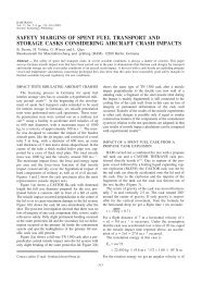
In 1980 BAM investigated the effect of an aeroplane<br />
crash simulating projectile impact onto a CASTOR IIa<br />
spent fuel transport cask within the licensing procedure<br />
started for the interim spent fuel storage facilities. At a<br />
test site of the Bundesamt für Wehrtechnik und Beschaffung,<br />
Erprobungsstelle Me<strong>pp</strong>en a projectile with a mass<br />
of 1000 kg and a velocity of 300 m.s�1 was impacted<br />
perpendicular to the centre of the cask’s lid system<br />
(Figure 5).<br />
Drop tests with casks from heights of 200 m were<br />
performed onto a concrete target to simulate the drop
from high bridges and to investigate the existing safety<br />
margins. The 1:2 model of the TN8/9 spent fuel cask<br />
(mass 4000 kg) was lifted with a helicopter to a height<br />
of 200 m (Figure 6a). With an impact velocity of nearly<br />
225 km.h �1 the cask penetrates the u<strong>pp</strong>er 600 mm thick<br />
reinforced concrete layer of the target (Figure 6b).<br />
<strong>TES</strong>T FACILITIES AT BAM, GERMANY<br />
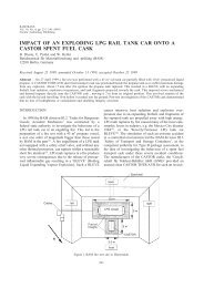
Figure 9. Fire and explosion test with a propane rail tank car and a CASTOR THTR/AVR spent fuel cask. (a) LPG rail tank car<br />
and CASTOR cask before the test. (b) Situation after the propane rail tank explosion.<br />
111<br />
Another example in this context is the drop test of a full<br />
scale CASTOR Ic from a height of 19.5 m onto a concrete<br />
highway target (8) (Figure 7). On behalf of the European<br />
Commission, BAM has carried out a study concerning<br />
the analysis of cask impacts onto a real target.<br />
This study included an extensive literature survey, and
the development of analytical and finite element calculation<br />
methods (9,10) . Figure 8 gives examples of the<br />
results for a cubic waste package.<br />
BAM has also carried out several test programmes (11–<br />
13) concerning the safety against brittle fracture of ductile<br />
iron casks. One of the test objects was a full-scale<br />
CASTOR VHLW with an artificial flaw of <strong>12</strong>0 mm<br />
depth in the 260 mm thick wall. The object was dro<strong>pp</strong>ed<br />
without impact limiters from a height of 14 m onto cylindrical<br />
rails, which were laid on the unyielding IAEA<br />
target: no fracture occurred (14) .<br />
An actual demonstration of existing safety margins of<br />
spent fuel casks is the impact of an exploding LPG rail<br />
tank car onto a CASTOR spent fuel cask (15) .On27<br />
April 1999 a fire test was performed with a 45 m 3 rail<br />
tank car partially filled with 10 m 3 pressurised liquid<br />
propane. A CASTOR THTR/AVR spent fuel transport<br />
cask was positioned beside the propane tank in order to<br />
suffer maximum damage from any explosion (Figure<br />
9a). The explosion of the tank imposed severe mechanical<br />
and thermal impacts onto the CASTOR cask<br />
(Figure 9b).<br />
GENERAL DESCRIPTION OF SI<strong>TES</strong> AND<br />
ROU<strong>TES</strong> OF ACCESS<br />
The 100,000 kg drop test facility and the open fire<br />
test facility are situated in Lehre–Kampstüh near to<br />
Braunschweig, a<strong>pp</strong>roximately 220 km from Berlin. The<br />
location of the new drop test and thermal test facility is<br />
on the BAM test area in Horstwalde, 50 km south-east<br />
B. DROSTE, T. QUERCETTI and B. GOGOLIN<br />
REFERENCES<br />
1. International Atomic Energy Agency. Regulations for the Safe Transport of Radioactive Materials — 1985 edition (as<br />
amended 1990). Safety Series, No. 6, (Vienna: IAEA) (1990).<br />
2. International Atomic Energy Agency. Regulations for the Safe Transport of Radioactive Material — 1996 edition (revised).<br />
Regulations TS-R-1 (ST-1, revised). Safety Standard Series. (Vienna: IAEA) (2000).<br />
3. Droste, B., Probst, U. and Wieser, G. Thermal Test Requirements and their Verification by Different Test Methods. In: Proc.<br />
of the 10th International Conference on Packaging and Transportation of Radioactive Materials (PATRAM ’92), Sept.13–<br />
18, 1992, Yokohama City, Japan. <strong>Vol</strong>. 3, <strong>pp</strong>. <strong>12</strong>63–<strong>12</strong>72.<br />
4. Zeisler, P., Droste, B. and Rödel, R. Current A<strong>pp</strong>roval Status and Test Procedures for Large Type B Packages in Germany.<br />
Int. J. Radioact. Mater. Trans. 8(1), 53–62 (1997).<br />
5. Gogolin, B., Droste, B. and Quercetti, T. Drop Test Program with the German ‘POLLUX’ Cask for Final Disposal of Spent<br />
Fuel. In: Proc. of the 11th International Conference on Packaging and Transportation of Radioactive Materials (PATRAM<br />
’95), Dec. 3–8, 1995, Las Vegas, USA. <strong>Vol</strong>. 1, <strong>pp</strong>. 159–166.<br />
6. Quercetti, T., Gogolin, B. and Droste, B. Integrity of the ‘POLLUX’ Cask for Final Disposal: Experimental Results of the<br />
Mechanical Tests. In: Proc. of the 11th International Conference on Packaging and Transportation of Radioactive Materials<br />
(PATRAM ’95), Dec. 3–8, 1995, Las Vegas, USA. <strong>Vol</strong>. 3, <strong>pp</strong>. 1091–1098.<br />
7. Schulz-Forberg, B. and Hübner, H. W. Klassifizierung und <strong>Sicherheit</strong>sreserven von Transportbehältern für radioaktive Stoffe.<br />
Forschungsbericht 230, 2. aktualisierte Auflage. (Berlin: BAM) (2000).<br />
8. Wieser, K. E., Jais, M. and Holzlöhner, U. Drop from the Reactor Building Crane — an event covered by the 9 m Drop Test<br />
Requirement? In: Proc. of the 7th International Conference on Packaging and Transportation of Radioactive Materials<br />
(PATRAM ’83), May 15–20, 1983, New Orleans, USA. <strong>Vol</strong>. 2, <strong>pp</strong>. 879–884.<br />
9. Droste, B. et al (BAM), Tso, C. F. et al (OAPIL), Hüggenberg, R. et al (GNB). Evaluation of Safety of Casks Impacting<br />
Different Kind of Targets. Final report to the Commission of the European Communities. Project EC-DG XVII/C/3. Contract<br />
No. B4–1020/D/96–017. Berlin, Germany, November 1998.<br />
10. Ballheimer, V., Probst, U. and Droste, B. Numerical Assessment of Spent Fuel Casks Impacting on Real Targets. Int. J.<br />
Radioact. Mater. Trans. 11(1–2), 45–51 (2000).<br />
1<strong>12</strong><br />
of Berlin. All other test sites are at BAM, D-<strong>12</strong>200<br />
Berlin, Unter den Eichen 87.<br />
AVAILABILITY OF FACILITIES<br />
The facilities are operated by BAM Division III.3,<br />
Safety of Transport and Storage Containers. Further<br />
information can be obtained from:<br />
B. Droste<br />
(Director and Professor)<br />
BAM, Bundesanstalt für Materialforschung und –prüfung<br />
Fachgru<strong>pp</strong>e III.3, <strong>Sicherheit</strong> von Transport und Lagerbehältern<br />
(Division III.3, Safety of Transport and Storage<br />
Containers)<br />
<strong>12</strong>200 Berlin, Germany<br />
Tel �49 (030) 8104 1330<br />
Fax �49 (030) 8104 1337<br />
E-mail bernhard.droste�bam.de<br />
B. Gogolin<br />
BAM, Bundesanstalt für Materialforschung und –prüfung<br />
Laboratorium III.31, Experimentelle Behälteruntersuchungen<br />
(Laboratory III.31, Testing of Containers)<br />
<strong>12</strong>200 Berlin, Germany<br />
Tel �49 (030) 8104 1331<br />
Fax �49 (030) 8104 1337<br />
E-mail bernd.gogolin@bam.de
<strong>TES</strong>T FACILITIES AT BAM, GERMANY<br />
11. Zencker, U., Quercetti, T., Wieser, G., Völzke, H. and Droste, B. Mechanical Impact Assessment of Cubic Waste Containers<br />
Depending on Target Construction. In: Proc. of the <strong>12</strong>th International Conference on Packaging and Transportation of Radioactive<br />
Materials (PATRAM ’98), May 10–15, 1998, Paris, France. <strong>Vol</strong>. 3, <strong>pp</strong>.1152–1157.<br />
<strong>12</strong>. Zencker, U., Zeisler, P. and Droste, B. Dynamic Fracture Mechanics Assessments for Cubic Ductile Cast Iron Containers.<br />
Int. J. Radioact. Mater. Trans. 11(1–2), 113–118 (2000).<br />
13. Wieser, K. E., Aurich, D. and Wüstenberg, H. The Status of Ductile Cast Iron Shi<strong>pp</strong>ing and Storage Containers in the<br />
Federal Republic of Germany. In: Proc. of the 9th International Conference on Packaging and Transportation of Radioactive<br />
Materials (PATRAM ’89), June 11–16, 1989, Washington, DC, USA. <strong>Vol</strong>. 2, <strong>pp</strong>. 701–711.<br />
14. Droste, B., Gogolin, B., Völzke, H., Quercetti, T. and Günther, B. Extended Drop Tests of DCI Casks with Artificial Flaws<br />
Demonstrating the Existing Safety Margins. Int. J. Radioact. Mater. Trans. 6(2–3), 177–182 (1995).<br />
15. Droste, B., Probst, U. and Heller, W. Impact of an Exploding LPG Rail Tank Car onto a CASTOR Spent Fuel Cask. Int. J.<br />
Radioact. Mater. Trans. 10(4), 231–240 (1999).<br />
113
114