pdf - 14652 kB - CARNet
pdf - 14652 kB - CARNet
pdf - 14652 kB - CARNet

You also want an ePaper? Increase the reach of your titles
YUMPU automatically turns print PDFs into web optimized ePapers that Google loves.
S. BockUS: A STUdy of ThE MIcRoSTRUcTURE And MEchAnIcAL pRopERTIES of ...<br />
used. The capacity of the not heated metal receiver of<br />
the machine was 2 tons. The cylindrical and rectangular<br />
specimens were cast by continuous casting.<br />
Effect of chemical composition on continuous casting<br />
ingots initial microstructure was investigated on various<br />
composition cast iron (eutectic Se = 0,8 - 1,0, ratio of<br />
silicon to carbon Si/c = 0,5 - 0,9).<br />
A microstructural analysis was made by optical microscopy.<br />
The graphite flake type, form, and size were defined<br />
by procedure described in the European Standard “cast<br />
iron - designation of microstructure of graphite” (En ISo<br />
945-1994). The procedure of quantitative metalography was<br />
carried out in accordance with Russian Standard “Iron castings<br />
with different form of graphite. Evaluation of structure“<br />
(GoST 3443-87). The microstructures observed were identified<br />
from the corresponding reference diagrams included<br />
in this standard. The tensile test was been determined on<br />
the machined test pieces prepared from samples cut from<br />
the continuously cast ingots in accordance with En 1561.<br />
The test piece diameter was 16 mm. The hardness was been<br />
determined as Brinell hardness from the samples cut from<br />
a casting, according to standard En 10003-1.<br />
results And discussion<br />
Investigation of the microstructure of the continuously<br />
cast 100 × 50 mm cross-section ingots showed that there<br />
was point graphite in surface of the ingots edges. It was<br />
situated in between dendrites. At about 10 mm distance<br />
from the surface the point graphite became substantially<br />
bigger but it was located among dendrites yet. Additionally,<br />
dendrites arms were substantially bigger than they<br />
were in the ingots surface. In 20 mm thickness layer from<br />
the surface almost all graphite was flaky. In the more<br />
deeply located layers the flakes fattened.<br />
There was only 6 percent of a pearlite in the ingots surface<br />
layer. Such little amount of pearlite results from cooling<br />
rate. high cooling rate raises the number of nucleation sites<br />
and reduces the coagulative and coalescentive processes.<br />
As a result, it reduces the carbon diffusion path during the<br />
eutectoid transformation and increases the amount of ferrite<br />
in the structure. on the other hand, there is not time enough<br />
for the growing of the nucleuses to take place, and finally<br />
there are many point graphite in the cast iron structure.<br />
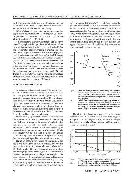
The effect of these two factors on continuously cast<br />
ingots was investigated on various composition cast iron<br />
(eutectic Se = 0,8 - 1,0; ratio of silicon to carbon Si/c =<br />
0,5 - 0,9). Results of the tests are generalized in the structural<br />
nomograph shown in the figure 1. The difference of<br />
presented nomograph from analogical nomographs is that<br />
zone with interdendritic graphite is included and the critical<br />
values of solidification rates are fixed; when approaching<br />
to these values, graphite formation way becomes different.<br />
Investigation of the effect of ratio Si/c on cast iron micro-<br />
288<br />
structure showed that, when Si/c = 0,5 - 0,6 one form of the<br />
graphite transforms to another in the narrow solidification<br />
rate interval. In the cast irons with ratio Si/c = 0,7 - 0,9 interdendritic<br />
graphite forms up at higher solidification rates.<br />
Thus, for continuous casting the cast iron with higher silicon<br />
to carbon ratio should be used for two reasons: to decrease<br />
occurrence of hard spots in a cast iron and to decrease<br />
zone of interdendritic graphite. Besides, grey cast iron with<br />
higher silicon to carbon ratio and lower degree of eutectic<br />
is stronger and resistant to cracking.<br />
The effect of carbon equivalent (cE) on the tensile<br />
strength in the 50 × 50 mm cross-section billet is given<br />
in figure 2. As this figure shows, the tensile strength<br />
decrease significantly with an increase in CE, as a result<br />
of increase in ferrite content.<br />
METALURGIJA 45 (2006) 4, 287-290