

Danfoss VLT 2800 Drives Quick Guide - CTi Automation
Danfoss VLT 2800 Drives Quick Guide - CTi Automation
Danfoss VLT 2800 Drives Quick Guide - CTi Automation

Create successful ePaper yourself
Turn your PDF publications into a flip-book with our unique Google optimized e-Paper software.
<strong>VLT</strong> <strong>2800</strong> <strong>Quick</strong> <strong>Guide</strong> 1 <strong>Quick</strong> <strong>Guide</strong><br />
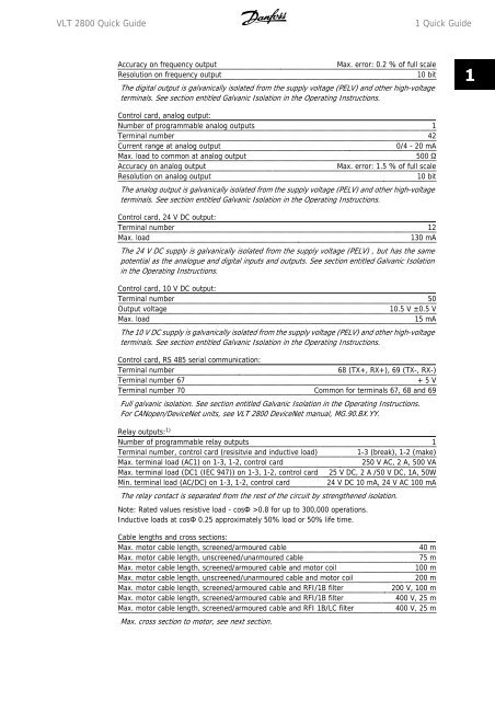
Accuracy on frequency output Max. error: 0.2 % of full scale<br />
Resolution on frequency output 10 bit<br />
The digital output is galvanically isolated from the supply voltage (PELV) and other high-voltage<br />
terminals. See section entitled Galvanic Isolation in the Operating Instructions.<br />
Control card, analog output:<br />
Number of programmable analog outputs 1<br />
Terminal number 42<br />
Current range at analog output 0/4 - 20 mA<br />
Max. load to common at analog output 500 Ω<br />
Accuracy on analog output Max. error: 1.5 % of full scale<br />
Resolution on analog output 10 bit<br />
The analog output is galvanically isolated from the supply voltage (PELV) and other high-voltage<br />
terminals. See section entitled Galvanic Isolation in the Operating Instructions.<br />
Control card, 24 V DC output:<br />
Terminal number 12<br />
Max. load 130 mA<br />
The 24 V DC supply is galvanically isolated from the supply voltage (PELV) , but has the same<br />
potential as the analogue and digital inputs and outputs. See section entitled Galvanic Isolation<br />
in the Operating Instructions.<br />
Control card, 10 V DC output:<br />
Terminal number 50<br />
Output voltage 10.5 V ±0.5 V<br />
Max. load 15 mA<br />
The 10 V DC supply is galvanically isolated from the supply voltage (PELV) and other high-voltage<br />
terminals. See section entitled Galvanic Isolation in the Operating Instructions.<br />
Control card, RS 485 serial communication:<br />
Terminal number 68 (TX+, RX+), 69 (TX-, RX-)<br />
Terminal number 67 + 5 V<br />
Terminal number 70 Common for terminals 67, 68 and 69<br />
Full galvanic isolation. See section entitled Galvanic Isolation in the Operating Instructions.<br />
For CANopen/DeviceNet units, see <strong>VLT</strong> <strong>2800</strong> DeviceNet manual, MG.90.BX.YY.<br />
Relay outputs: 1)<br />
Number of programmable relay outputs 1<br />
Terminal number, control card (resisitvie and inductive load) 1-3 (break), 1-2 (make)<br />
Max. terminal load (AC1) on 1-3, 1-2, control card 250 V AC, 2 A, 500 VA<br />
Max. terminal load (DC1 (IEC 947)) on 1-3, 1-2, control card 25 V DC, 2 A /50 V DC, 1A, 50W<br />
Min. terminal load (AC/DC) on 1-3, 1-2, control card 24 V DC 10 mA, 24 V AC 100 mA<br />
The relay contact is separated from the rest of the circuit by strengthened isolation.<br />
Note: Rated values resistive load - cosΦ >0.8 for up to 300,000 operations.<br />
Inductive loads at cosΦ 0.25 approximately 50% load or 50% life time.<br />
Cable lengths and cross sections:<br />
Max. motor cable length, screened/armoured cable 40 m<br />
Max. motor cable length, unscreened/unarmoured cable 75 m<br />
Max. motor cable length, screened/armoured cable and motor coil 100 m<br />
Max. motor cable length, unscreened/unarmoured cable and motor coil 200 m<br />
Max. motor cable length, screened/armoured cable and RFI/1B filter 200 V, 100 m<br />
Max. motor cable length, screened/armoured cable and RFI/1B filter 400 V, 25 m<br />
Max. motor cable length, screened/armoured cable and RFI 1B/LC filter 400 V, 25 m<br />
Max. cross section to motor, see next section.<br />
MG.28.M1.02 - <strong>VLT</strong> ® is a registered <strong>Danfoss</strong> trademark 31<br />
1


