DPA UPScale™ ST Technical Specifications - Atek Teknik A/S
DPA UPScale™ ST Technical Specifications - Atek Teknik A/S
DPA UPScale™ ST Technical Specifications - Atek Teknik A/S

You also want an ePaper? Increase the reach of your titles
YUMPU automatically turns print PDFs into web optimized ePapers that Google loves.
Edition 01.11.2009<br />
<strong>DPA</strong> UPScale <strong>ST</strong><br />
<strong>Technical</strong> <strong>Specifications</strong><br />
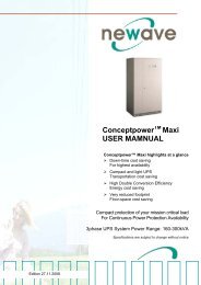
<strong>DPA</strong> UPSCALE TM highlights at a glance<br />
<strong>DPA</strong> UPScale with Safe-Swap Modules (SSM)<br />
For premium power protection availability<br />
Low total Cost of Ownership (TCO)<br />
Cost saving during entire life-cycle<br />
Flexibility/Scalability<br />
Ease of power upgrade, pay as you grow<br />
Enhanced Serviceability<br />
Rapid fault recovery<br />
Link to Newavewatch TM<br />
Instantaneous fault recognition<br />
Safe-Swap Modular Power Protection<br />
Power range: 10-120KW per rack<br />
<strong>Specifications</strong> are subject to change without notice
TABLE OF CONTENTS<br />
Section-10<br />
10.1 <strong>DPA</strong> UPScale <strong>ST</strong> SY<strong>ST</strong>EM DESCRIPTION ..............................................................................................3<br />
10.2 TECHNICAL CHARACTERI<strong>ST</strong>ICS ............................................................................................................4<br />
10.2.1 MECHANICAL CHARACTERI<strong>ST</strong>ICS FRAMES AND MODULES..........................................................4<br />
10.3 INPUT CHARACTERI<strong>ST</strong>ICS ......................................................................................................................5<br />
10.3.1 GRAPH: INPUT PF VERSUS % LOAD..................................................................................................6<br />
10.3.2 GRAPH: INPUT DI<strong>ST</strong>ORTION THDI VERSUS % LOAD.......................................................................6<br />
10.4 BATTERY CHARACTERI<strong>ST</strong>ICS................................................................................................................7<br />
10.5 OUTPUT CHARACTERI<strong>ST</strong>ICS ..................................................................................................................7<br />
10.5.1 GRAPH: AC – AC EFFICIENCY with Linier load @ cosphi 1 ................................................................8<br />
10.5.2 GRAPH: Output Power in KW and KVA VERSUS cosphi.....................................................................8<br />
10.6 ENVIRONMENTAL CHARACTERI<strong>ST</strong>ICS .................................................................................................9<br />
10.7 <strong>ST</strong>ANDARDS..............................................................................................................................................9<br />
10.8 COMMUNICATION ...................................................................................................................................10<br />
10.8.1 POWER MANAGEMENT DISPLAY (PMD)..........................................................................................10<br />
10.8.2 MIMIC DIAGRAM..................................................................................................................................10<br />
10.8.3 DISPLAY...............................................................................................................................................10<br />
10.8.4 CU<strong>ST</strong>OMER INTERFACES Terminals X1…X2 ..................................................................................11<br />
10.8.5 CU<strong>ST</strong>OMER INPUTS DRY PORT s: Terminal block X2......................................................................11<br />
10.8.6 CU<strong>ST</strong>OMER OUTPUTS DRY PORTs : Terminal blocks X1...............................................................11<br />
10.9 OPTIONS ..................................................................................................................................................12<br />
10.9.1 MODEM/ETHERNET CARD / Newavewatch TM MANAGEMENT SOFTWARE ...................................12<br />
10.9.2 SNMP card / WaveMon Management Software..................................................................................13<br />
10.9.3 BATTERY CABINETS ..........................................................................................................................13<br />
10.10 BATTERY AUTONOMIES........................................................................................................................14<br />
10.10.1 Examples of Internal Battery Autonomy of <strong>DPA</strong> UPScale <strong>ST</strong>40 and <strong>ST</strong> 60 ....................................14<br />
10.10.2 Examples of External Battery Autonomy..........................................................................................15<br />
10.11 IN<strong>ST</strong>ALLATION PLANNING ....................................................................................................................16<br />
10.11.1 HEAT DISSIPATION PER MODULE WITH NON-LINEAR LOAD...................................................16<br />
10.12 WIRING AND BLOCK DIAGRAMS FOR ALL FRAMES AND MODULES.............................................17<br />
10.12.1 TERMINAL CONNECTIONS OVERVIEW .......................................................................................17<br />
10.12.2 SINGLE FEED INPUT ......................................................................................................................18<br />
10.12.3 SINGLE FEED INPUT / Cable Sections...........................................................................................18<br />
10.12.4 DUAL FEED INPUT..........................................................................................................................19<br />
10.12.5 Dual FEED INPUT / Cable Sections.................................................................................................19<br />
www.newaveups.com<br />
04-0313_S10_NW_TDS<strong>DPA</strong>_UPSCALE_<strong>ST</strong>_GB_091101.DOC Page 2/19<br />
Printed in Switzerland – Modifications reserved
Section-10<br />
10.1 <strong>DPA</strong> UPScale <strong>ST</strong> SY<strong>ST</strong>EM DESCRIPTION<br />
In environments that demand zero downtime, continuous power protection availability is essential. In order<br />
to respond to today’s dynamic IT and process-related environments that experience daily change through<br />
new server technologies, migration and centralization, resilient and easily adaptable power protection<br />
concepts are required.<br />
<strong>DPA</strong> UPScale is the foundation for continuous power protection availability of network-critical<br />
infrastructures in enterprise data centers where business continuity has paramount importance and in<br />
process control environment where manufacturing continuity is essential.<br />
NEWAVE <strong>DPA</strong> UPScale’s is a second generation high-power-density (HPD), leading-edge doubleconversion<br />
power protection technology that has standardized on a modular component approach which<br />
helps speed deployment, improve adaptability and increase system availability while reducing total cost of<br />
ownership.<br />
<strong>DPA</strong> UPScale’s is a unique on-demand architecture that integrates the power rack, power distribution unit,<br />
back-up battery rack and monitoring and management solutions to allow easy selection of optimized<br />
configurations.<br />
<strong>DPA</strong> UPScale’s (Distributed Parallel Architecture) provides highest availability, unmatched flexibility and at<br />
the same time lowest cost of ownership in IT environments.<br />
This <strong>Technical</strong> Specification provides detailed technical information on the mechanical, electrical and<br />
environmental performance of the <strong>DPA</strong> UPScale model types that can support to give answers to tender<br />
and end-user requirements. The <strong>DPA</strong> UPScale family was designed to respond to the most stringent<br />
safety, EMC and other important UPS standards. <strong>DPA</strong> UPScale family is offered in two types of solutions:<br />
A) <strong>DPA</strong> UPScale <strong>ST</strong> is a rack-mounted modular design offering 4-types of Racks (Frames) types.<br />
This solution can accommodate 2 types of <strong>DPA</strong> UPScale Rack based Modules for a wide range of power<br />
requirements:<br />
<strong>DPA</strong> UPScale <strong>ST</strong> (standard) frames:<br />
• <strong>DPA</strong> UPScale <strong>ST</strong> 40 (40kW)<br />
• <strong>DPA</strong> UPScale <strong>ST</strong> 60 (60kW)<br />
• <strong>DPA</strong> UPScale <strong>ST</strong> 80 (80kW)<br />
• <strong>DPA</strong> UPScale <strong>ST</strong> 120 (120kW)<br />
<strong>DPA</strong> UPScale Modules types:<br />
• UPScale M 10 (kW)<br />
• UPScale M 20 (kW)<br />
Key Features of <strong>DPA</strong> UPScale <strong>ST</strong> and <strong>DPA</strong> UPScale RI:<br />
• Highest Availability<br />
Modular, Decentralized Parallel Architecture (<strong>DPA</strong>)<br />
Near-zero down time<br />
• High Power Density (up to 272kW / m 2 ),<br />
Small Footprint<br />
Space-saving of expensive floor space<br />
• Unity Output Power Factor No de-rating for loads with Unity PF<br />
Full power for loads with unity PF<br />
• Highest Efficiency even with partial loads Energy cost saving during UPS-life-cycle<br />
Efficiency = 94.5 - 95.5% for loads 25-100%<br />
(depending on Module power and type of load)<br />
• Very low input current distortion THDi Gen-set power and installation cost saving<br />
THDi = < 3@ 100 % load<br />
www.newaveups.com<br />
04-0313_S10_NW_TDS<strong>DPA</strong>_UPSCALE_<strong>ST</strong>_GB_091101.DOC Page 3/19<br />
Printed in Switzerland – Modifications reserved
Section-10<br />
10.2 TECHNICAL CHARACTERI<strong>ST</strong>ICS<br />
10.2.1 MECHANICAL CHARACTERI<strong>ST</strong>ICS FRAMES AND MODULES<br />
<strong>DPA</strong> UPScale <strong>ST</strong> UPScale <strong>ST</strong> 40 UPScale <strong>ST</strong> 60 UPScale <strong>ST</strong> 80 UPScale <strong>ST</strong> 120<br />
<strong>DPA</strong> UPScale <strong>ST</strong><br />
FRAMES<br />
Configuration<br />
accommodates:<br />
Max.<br />
2 module<br />
(10 or 20kW)<br />
and<br />
80 x 7/9Ah<br />
batteries<br />
3 modules<br />
(10 or 20kW)<br />
and<br />
240 x 7/9Ah<br />
batteries<br />
4 modules<br />
(10 or 20kW)<br />
and<br />
NO batteries<br />
6 modules<br />
(10 or 20kW)<br />
and<br />
NO batteries<br />
Max. Power connection kW 40 60 80 120<br />
Dimensions (WxHxD) mm 550x1135x770 550x1975x770 550x1135x770 550x1975x770<br />
Weight of Empty Frame<br />
w/o modules and<br />
w/o batteries<br />
Weight of Frame<br />
with modules and<br />
w/o batteries<br />
Colours<br />
MODULES<br />
kg 92 173 82 133<br />
kg<br />
130 up to 136<br />
(with 2 Module)<br />
229 up to 238<br />
(with 3 Module)<br />
157up to 169<br />
(with 4 Modules)<br />
245 up to 263<br />
(with 6 Modules)<br />
Front : Graphite grey (Pulverlacke No. 4222903402 serie 09RCCAT1)<br />
Side walls: Graphite grey (Pulverlacke No. 4222903402 serie 09RCCAT1)<br />
UPScale M 10 UPScale M 20<br />
Output Active Rated Power KW 10 20<br />
Variable Number of 12V<br />
Battery Blocks<br />
Dimensions (WxHxD)<br />
No. 20-50 *1) 30-50 *1)<br />
mm 488 x 132 x 540<br />
(3 HU)<br />
Weight UPS Module kg 18.6 21.5<br />
Colors Front : RAL 7016<br />
Note : * 1) Depending of the effective load in kW used by the module (see chapter 10.5 Battery characteristics)<br />
www.newaveups.com<br />
04-0313_S10_NW_TDS<strong>DPA</strong>_UPSCALE_<strong>ST</strong>_GB_091101.DOC Page 4/19<br />
Printed in Switzerland – Modifications reserved
10.3 INPUT CHARACTERI<strong>ST</strong>ICS<br />
Module Range UPScale M 10 or M 20<br />
Section-10<br />
Module Type UPScale M 10 UPScale M 20<br />
Output Rated Power per Module cosphi 0.8 kVA 10 20<br />
Output Rated Power per Module cosphi 1.0 KW 10 20<br />
Nominal Input Voltage V 3x380/220V+N, 3x400V/230V+N, 3x415/240V+N<br />
Input Voltage Tolerance<br />
(ref to 3x400/230V) for Loads in %:<br />
V<br />
(-23%/+15%) 3x308/177 V to 3x460/264 V for
10.3.1 GRAPH: INPUT PF VERSUS % LOAD<br />
Input power factor<br />
1<br />
0.8<br />
0.6<br />
0.4<br />
0.2<br />
0<br />
Input power factor versus load (Leading)<br />
0.96<br />
0.985<br />
0.99<br />
25 50 75 100<br />
load %<br />
10.3.2 GRAPH: INPUT DI<strong>ST</strong>ORTION THDI VERSUS % LOAD<br />
Input THDi %<br />
6.0<br />
5.5<br />
5.0<br />
4.5<br />
4.0<br />
3.5<br />
3.0<br />
2.5<br />
2.0<br />
1.5<br />
Input Current Distortion THDi<br />
4.0<br />
3.7<br />
3.4<br />
25 50 75 100<br />
Load %<br />
3.0<br />
0.99<br />
Section-10<br />
www.newaveups.com<br />
04-0313_S10_NW_TDS<strong>DPA</strong>_UPSCALE_<strong>ST</strong>_GB_091101.DOC Page 6/19<br />
Printed in Switzerland – Modifications reserved
10.4 BATTERY CHARACTERI<strong>ST</strong>ICS<br />
Module Range UPScale M 10 or M 20<br />
Module Type UPScale M 10 UPScale M 20<br />
Variable Number of 12V Battery Blocks No. 20-50 *1) 30-50 *1)<br />
Maximum Battery Charger Current A 4 A 4 A<br />
Battery Charging Curve Ripple free ; IU (DIN 41773)<br />
Temperature compensation Standard (temp. sensor optional)<br />
Battery Test Automatic and periodically (adjustable)<br />
Battery Type Maintenance free VRLA or NiCd<br />
Note : * 1) Depending of the effective load in kW used by the module (see table below)<br />
Section-10<br />
Description UPScale Module M 10 UPScale Module M 20<br />
Number of battery blocks 20 24 28 30 34-50 30 34 36 40 40 48-50<br />
Max. Power in KW 6 8 8 10 10 12 12 16 20 16 20<br />
Max. autonomy (min.) 5 5 5 5 999 5 999 5 5 999 999<br />
10.5 OUTPUT CHARACTERI<strong>ST</strong>ICS<br />
Module Range UPScale M 10 or M 20<br />
Module Type UPScale M 10 UPScale M 20<br />
Output Rated Power per Module cosphi 0.8 kVA 10 20<br />
Output Rated Power per Module cosphi 1.0 KW 10 20<br />
Output Current In @ cosphi 1.0 (400 V) A 14.5 29<br />
Output Rated Voltage V 3x380/220V or 3x400/230V or 3x415/240V<br />
Output Voltage Stability %<br />
Static:<br />
Dynamic (Step load 0%-100% or 100%-0%)<br />
< +/- 1%<br />
< +/- 4%<br />
Output Voltage Distortion %<br />
With Linear Load<br />
With Non-linear Load (EN62040-3:2001)<br />
< 1.5%<br />
< 3%<br />
Output Frequency Hz 50 Hz or 60 Hz<br />
Synchronized with mains < +/- 2 %<br />
Output Frequency Tolerance % (selectable for bypass operation) or < +/- 4 %<br />
Bypass operation<br />
Permissible Unbalanced Load<br />
(All 3 phases regulated independently)<br />
Phase Angle Tolerance<br />
(With 100 % Unbalanced load)<br />
Free running +/- 0.1 %<br />
At Nominal Input voltage of 3x400 V +/- 15%<br />
or 190 V to 264 V ph-N<br />
% 100%<br />
Deg. +/- 0 deg.<br />
Overload Capability on Inverter %<br />
125 % load<br />
150 % load<br />
10 min.<br />
60 sec.<br />
Output short capability (RMS) A<br />
Inverter :<br />
Bypass :<br />
3 x In during 200 ms<br />
10 x In during 20 ms<br />
Crest - Factor 3 : 1<br />
www.newaveups.com<br />
04-0313_S10_NW_TDS<strong>DPA</strong>_UPSCALE_<strong>ST</strong>_GB_091101.DOC Page 7/19<br />
Printed in Switzerland – Modifications reserved
10.5.1 GRAPH: AC – AC EFFICIENCY with Linier load @ cosphi 1<br />
Efficiency up to 1 % higher with output PF cosphi 0.8<br />
Details refer to paragraph 10.7 Environmental Characteristics<br />
100<br />
95<br />
90<br />
85<br />
80<br />
75<br />
70<br />
%<br />
Linear Load (cosphi=1)<br />
94.5<br />
95<br />
95.5<br />
UPScale M10 / M20<br />
10.5.2 GRAPH: Output Power in KW and KVA VERSUS cosphi<br />
22.0<br />
21.0<br />
20.0<br />
19.0<br />
18.0<br />
17.0<br />
16.0<br />
15.0<br />
14.0<br />
13.0<br />
12.0<br />
11.0<br />
10.0<br />
9.0<br />
8.0<br />
7.0<br />
6.0<br />
5.0<br />
4.0<br />
3.0<br />
2.0<br />
1.0<br />
0.0<br />
95.5<br />
25 50 75 100 Load %<br />
UPScale Module UPScale Module<br />
M 10<br />
M 20<br />
cosphi kW kVA kW kVA<br />
0.9 9 10 18 20<br />
0.95 9.5 10 19 20<br />
unity 1 10 10 20 20<br />
0.95 10 10 19 20<br />
0.9 9 10 18 20<br />
0.85 8.5 10 17 20<br />
0.8 8 10 16 20<br />
0.75 7.5 10 15 20<br />
0.7 7 10 14 20<br />
0.6 6 10 12 20<br />
Ind.<br />
UPSCALE 10 (kW)<br />
UPSCALE 10 (kVA)<br />
UPSCALE 20 (kW)<br />
UPSCALE 20 (kVA)<br />
0.9 1.0 1.0 1.0 0.9 0.9 0.8 0.8 0.7 0.6<br />
Changes of this table without notice – modifications reserved<br />
Section-10<br />
www.newaveups.com<br />
04-0313_S10_NW_TDS<strong>DPA</strong>_UPSCALE_<strong>ST</strong>_GB_091101.DOC Page 8/19<br />
Printed in Switzerland – Modifications reserved
10.6 ENVIRONMENTAL CHARACTERI<strong>ST</strong>ICS<br />
Module Range UPScale M 10 or M 20<br />
Section-10<br />
Module Type UPScale M 10 UPScale M 20<br />
Audible Noise with 100% / 50% Load dBA 55 / 49 57 / 49<br />
Operation temperature °C 0 – 40<br />
Ambient Temperature for Batteries (recommended) °C 20 – 25<br />
Storage Temperature °C -25 - +70<br />
Battery Storage Time at Ambient Temperature Max. 6 months<br />
Max. altitude (above sea level) m 1000m (3300ft) without de-rating<br />
Meter above sea level (m / ft) De-Rating Factor for Power<br />
De-rating factor for use at altitudes above 1000m sea<br />
level according (IEC 62040-3)<br />
1500 / 4850<br />
2000 / 6600<br />
2500 / 8250<br />
0.95<br />
0.91<br />
0.86<br />
3000 / 9900 0.82<br />
Relative Air-humidity Max. 95% (non-condensing)<br />
Accessibility<br />
Totally front accessibility for service and<br />
maintenance (no need for side, top or rear access)<br />
Positioning Min. 20 cm rear space (required for fan)<br />
Input and Output Power Cabling From the bottom on the front<br />
Efficiency AC-AC up to (at cosphi 1.0)<br />
(depending on Module power)<br />
%<br />
Load<br />
M 20<br />
M 10<br />
:<br />
:<br />
:<br />
100 %<br />
95.5%<br />
95.5%<br />
75 %<br />
95.5%<br />
95.5%<br />
50%<br />
95%<br />
95%<br />
25%<br />
94.5%<br />
94.5%<br />
Efficiency with Linear Load at cosphi =0.8 ind<br />
Efficiency Non-linear Load (EN 62040-1-1:2003)<br />
Typically up to 1 % higher of above values<br />
Typically up to 1 % lower of above values<br />
Eco-Mode efficiency at 100% load % 98 %<br />
10.7 <strong>ST</strong>ANDARDS<br />
Safety EN 62040-1-1, EN 60950-1<br />
Electromagnetic Compatibility<br />
EN 61000-6-4 Prod.standard: EN 62040-2<br />
EN 61000-6-2 Prod.standard: EN 62040-2<br />
EN 61000-4-2, EN 61000-4-3 - EN 61000-4-4 - EN 61000-4-5 - EN 61000-4-6<br />
EMC Classification for M 10 M 20<br />
Emission Class C2 C2<br />
Immunity Class C3 C3<br />
Performance EN62040-3<br />
Product certification CE<br />
Degree of protection IP 20<br />
www.newaveups.com<br />
04-0313_S10_NW_TDS<strong>DPA</strong>_UPSCALE_<strong>ST</strong>_GB_091101.DOC Page 9/19<br />
Printed in Switzerland – Modifications reserved
10.8 COMMUNICATION<br />
Power Management Display (PMD) 1 LCD display for each module<br />
RJ45 Plug (Not used) RJ45 Plug (for future options)<br />
Customer Interfaces : Outputs<br />
DRY PORT X 2<br />
Customer Interfaces : Inputs<br />
DRY PORT X1<br />
Serial ports RS232 on Sub-D9<br />
5 voltage free contacts<br />
For remote signaling and automatic computer shutdown<br />
1 x Remote Shut down [EMERGENCY OFF (Normally closed)]<br />
2 x Programmable Customer’s Inputs<br />
(1 st default as GEN-ON (Normally open)<br />
(2 nd free Programmable Customer’s Inputs (Normally open)<br />
1 x Temp. Sensor for Battery Control<br />
1 x 12 Vdc output (max. 200mA)<br />
1 x system frame<br />
For monitoring and integration in network management<br />
USB 1x For monitoring and software management<br />
Slot for SNMP<br />
SNMP card (optional)<br />
For monitoring and integration in network management<br />
Slot for Newavewatch TM Newavewatch TM card (optional) for Premium Power Protection<br />
Section-10<br />
10.8.1 POWER MANAGEMENT DISPLAY (PMD)<br />
The user-friendly PMD consists of three parts the MIMIC DIAGRAM, CONTROL KEYS and LCD that<br />
provides the necessary monitoring information about the UPS.<br />
10.8.2 MIMIC DIAGRAM<br />
The mimic diagram serves to give the general status of the UPS. The LED-indicators show the power flow<br />
status and in the event of mains failure or load transfer from inverter to bypass and vice-versa the<br />
corresponding LED-indicators will change color from green (normal) to red (warning). The LED’s LINE 1<br />
(rectifier) and LINE 2 (bypass) indicate the availability of the mains power supply. The LED’s INVERTER<br />
and BYPASS if green indicate which of the two are supplying power to the critical load. When the LEDindicator<br />
BATTERY is lit it means that the battery due to mains failure is supplying the load. The LEDindicator<br />
ALARM is a visual indication of any internal or external alarm condition. At the same time the<br />
audible alarm will be activated.<br />
10.8.3 DISPLAY<br />
The 2 x 20 character LCD simplifies the communication with the UPS. The menu driven LCD enables the<br />
access to the EVENT REGI<strong>ST</strong>ER, or to monitor the input and output U, I, f, P, Autonomy Time and other<br />
Measurement’s, to perform commands like start-up and shut-down of INVERTER or load transfer from<br />
INVERTER to BYPASS and vice-versa and finally it serves for the DIAGNOSIS (SERVICE MODE) for<br />
adjustments and testing (for more details see the USER MANUAL of <strong>DPA</strong> UPScale TM ).<br />
Power Management Display (PMD)<br />
of <strong>DPA</strong> UPScale<br />
www.newaveups.com<br />
04-0313_S10_NW_TDS<strong>DPA</strong>_UPSCALE_<strong>ST</strong>_GB_091101.DOC Page 10/19<br />
Printed in Switzerland – Modifications reserved
10.8.4 CU<strong>ST</strong>OMER INTERFACES Terminals X1…X2<br />
10.8.5 CU<strong>ST</strong>OMER INPUTS DRY PORT s: Terminal block X2<br />
Connection of Remote Shut down facilities, Generator Operation, Customers specials<br />
(see UM Section 9 / OPTIONS)<br />
10.8.6 CU<strong>ST</strong>OMER OUTPUTS DRY PORTs : Terminal blocks X1<br />
Provision of signals for the automatic and orderly shutdown of servers, AS400 or Automation building<br />
systems<br />
All voltage free contacts are rated 60 VAC max. and 500 mA max.:<br />
All the interfaces are connected to Phoenix Spring terminals with wires : 0.5 mm2<br />
Block Terminal Contact Signal On Display Function<br />
X2<br />
X1<br />
X2 / 1 NO MAINS_OK Mains Present<br />
X2 / 2 NC ALARM Mains Failure<br />
X2 / 3 C Common<br />
X2 / 4 NO LOAD_ON_INV Load on Inverter<br />
X2 / 5 NC Message (Load on Mains bypass)<br />
X2 / 6 C Common<br />
X2 / 7 NO BATT_LOW Battery Low<br />
X2 / 8 NC ALARM Battery OK<br />
X2 / 9 C Common<br />
X2 / 10 NO LOAD_ON_MAINS Load on bypass (Mains)<br />
X2 / 11 NC Message (Load on Inverter)<br />
X2 / 12 C Common<br />
X2 / 13 NO COMMON_ALARM Common Alarm (System)<br />
X2 / 14 NC ALARM NO Alarm Condition<br />
X2 / 15 C Common<br />
X1 / 1 IN + 12Vdc Customer IN 1 (default as Generator Operation )<br />
X1 / 2 GND GND (NC = Generator ON)<br />
X1 / 3 IN + 12Vdc Customer IN 2<br />
X1 / 4 GND GND (Function on request, to be defined)<br />
X1 / 5 IN + 3.3Vdc Temperature Battery<br />
X1 / 6 GND GND<br />
Section-10<br />
(If connected , the battery charger current if depending of the battery<br />
temp.)<br />
X1 / 7 IN + 12Vdc Remote Shut down<br />
X1 / 8 GND GND<br />
(Do not remove the factory mounted bridge until external Remote Shut<br />
down is connected)<br />
X1 / 9 IN + 12Vdc 12 Vdc sourse<br />
X1 / 10 GND GND (max. 200 mA load)<br />
Phoenix Spring Terminals (X1…X2) Connection<br />
www.newaveups.com<br />
04-0313_S10_NW_TDS<strong>DPA</strong>_UPSCALE_<strong>ST</strong>_GB_091101.DOC Page 11/19<br />
Printed in Switzerland – Modifications reserved
10.9 OPTIONS<br />
- Modem/Ethernet card or Modem/GSM card for Newavewatch TM Management Software<br />
- SNMP card and WaveMon Management Software , Modbus Protocol<br />
- External Battery Cabinets<br />
- In/Output Transformator for special voltages on request<br />
- Temp. sensor for battery temp. control<br />
Section-10<br />
10.9.1 MODEM/ETHERNET CARD / Newavewatch TM MANAGEMENT SOFTWARE<br />
Newavewatch TM is a redundant remote monitoring and management service which is a part of the Premium<br />
Power Protection Concept, providing you with peace-of-mind protection, knowing the mission critical facility<br />
is under careful, continuous watch 24/7/365. There are two different solution cards Modem/Ethernet or<br />
Modem/GSM to connect the UPS to the outside world.<br />
Continuous monitoring is an affordable insurance policy to detect and warn before they become a crisis.<br />
Acquire key performance parameter and productivity information in real-time to empower you with the<br />
details needed to better understand machine performance and faster troubleshoot downtime events.<br />
Early warning system, so problems can be addressed before they become a real threat to the load.<br />
Professional experts, your virtual service technician onside.<br />
Total transparency of information and actions performed like Notification of all critical status changes,<br />
Coordination of equipment service, Reporting of all alarms with priorities.<br />
What are the features?<br />
• Redundant and secure communication<br />
• Alarm acknowledgment<br />
• Priority driven Management (with escalation)<br />
Comprehensive Management System<br />
– Reception and management of alarm calls from UPS<br />
– Storage of UPS Data in a database exportable in a CVS-format for easy handling in Excel<br />
– Unlimited number of UPS that can be managed<br />
– User administration with passwords and permission-level<br />
– Administration of Log file<br />
– Data logging with statistical analysis and diagnostics, report<br />
UPS-System<br />
1….1000<br />
Alarm-<br />
Situation<br />
Visualization of the UPS data:<br />
• Current status (“single” and “parallel” operation)<br />
• Measured values for single or three phase<br />
• Recording function including graphs with zooming capabilities for selected measured values<br />
• Display of event log file<br />
• Display of UPS Parameters<br />
• Web Server functionality, for data access from any Web Browser<br />
Redundant<br />
Interface Card<br />
MODEM<br />
Call back<br />
Modem GSM<br />
Modem<br />
Network interface<br />
(ethernet)<br />
SSL<br />
INTERNET<br />
MODEM<br />
Communication<br />
Interface<br />
1<br />
…<br />
.1<br />
Communication<br />
Interface<br />
INTERNET<br />
Management<br />
Station<br />
www.newaveups.com<br />
04-0313_S10_NW_TDS<strong>DPA</strong>_UPSCALE_<strong>ST</strong>_GB_091101.DOC Page 12/19<br />
Printed in Switzerland – Modifications reserved
Section-10<br />
10.9.2 SNMP card / WaveMon Management Software<br />
The Simple Network Management Protocol (SNMP) is a worldwide-standardized communication-protocol.<br />
It is used to monitor any device in the network via simple control language. The UPS-Management<br />
Software WaveMon also provides its data in this SNMP format with its internal software agent. The<br />
operating system you are using must support the SNMP protocol. We offer our WaveMon software with<br />
SNMP functionality for Novell, OS/2, all Windows running on INTEL and ALPHA, DEC VMS, Apple.<br />
Two types of SNMP interfaces with identical functionality are available: an external SNMP-Adapter (Box)<br />
and an internal SNMP-Card. Both can manage a parallel system (N modules) and return either global<br />
values - which are consistent for the whole parallel system - or specific values from the single modules.<br />
UPS<br />
10.9.3 BATTERY CABINETS<br />
S-type = For Separate. Battery<br />
C-type = For Common. Battery<br />
BATTERY FRAMES<br />
Configuration accommodates:<br />
Battery fuses / Max. Batt. Strings :<br />
Terminals :<br />
Battery fuses / Max. Batt. Strings<br />
Terminals :<br />
Max.<br />
S-type<br />
C-type<br />
CBAT-UPScale-120<br />
S-type or C-type<br />
120 Batt. block x 24Ah/28Ah<br />
on 8 shelf<br />
3x5=15 blocks/shelf<br />
9 / 9<br />
(Terminal 9 x 16/25mm2)<br />
9 / 9<br />
+ Com. Connection Bar<br />
3 x (2xM8) +PE 2xM8<br />
CBAT-UPScale-200<br />
S-type or C-type<br />
200 Batt. blocks x 24Ah/28Ah<br />
on 7 shelf<br />
6x5=30 blocks/shelf<br />
10 / 10<br />
(Terminal 15 x 16/25mm2)<br />
10 / 10<br />
+ Com. Connection Bar<br />
3 x (2xM10) +PE 2xM10<br />
Fuse Type (Very Fast acting) A 3x100 A 5x100A<br />
Dimensions (WxHxD) mm 730x1975x800 1200x1975x800<br />
Weight with trays and w/o batteries kg 290 410<br />
Possible Battery configurations<br />
within the Battery Cabinets<br />
Ethernet<br />
External SNMP-Adapter<br />
Internal SNMP-Card<br />
Battery Configurations<br />
(1x40)x28Ah<br />
(2x40)x28Ah<br />
(3x40)x28Ah<br />
(2x50)x28Ah<br />
Battery Configurations<br />
(1x40)x28Ah<br />
(2x40)x28Ah<br />
(3x40)x28Ah<br />
(4x40)x28Ah<br />
(5x40)x28Ah<br />
(2x50x28Ah)<br />
(4x50)x28Ah<br />
www.newaveups.com<br />
04-0313_S10_NW_TDS<strong>DPA</strong>_UPSCALE_<strong>ST</strong>_GB_091101.DOC Page 13/19<br />
Printed in Switzerland – Modifications reserved<br />
9
10.10 BATTERY AUTONOMIES<br />
10.10.1 Examples of Internal Battery Autonomy of <strong>DPA</strong> UPScale <strong>ST</strong>40 and <strong>ST</strong> 60<br />
Module Type UPScale M 10<br />
UPScale M 20<br />
Module need at least 48 blocks for full power<br />
or minimum 40 blocks for 16kW<br />
Internal Separate Battery configuration Battery Autonomy in (min.) per Module<br />
Section-10<br />
Frame Type Separate Battery / Module 8kW 10kW 12kW 16kW 20KW<br />
UPScale <strong>ST</strong> 40<br />
max. 80 blocks<br />
up to 2 modules<br />
(1x40)x7Ah / Module 8 6 5<br />
UPScale <strong>ST</strong> 40<br />
max. 80 blocks<br />
1 modules ONLY<br />
(1x50)x7Ah / Module 11 8. 7 4<br />
UPScale <strong>ST</strong> 60<br />
max. 240 blocks<br />
up to 3 modules<br />
UPScale <strong>ST</strong> 60<br />
max. 240 blocks<br />
up to 3 modules<br />
(1x40)x7Ah / Module 8 6 5<br />
(2x40)x7Ah / Module 21 15 12 8 5<br />
Internal Common Battery configuration Battery Autonomy in (min.) for Tot. System Power<br />
With 1 Module<br />
Module Type<br />
Total System Power<br />
1 x UPScale M 10<br />
8kW 10kW 12kW<br />
1 x UPScale M 20<br />
16kW 20KW<br />
UPScale <strong>ST</strong> 40 or<br />
UPScale <strong>ST</strong> 60<br />
1x (2x40)x7Ah 21 15 12 8 5<br />
UPScale <strong>ST</strong> 60 2x (1x50)x7Ah 28 21 16 11 8<br />
UPScale <strong>ST</strong> 60 3x (1x40)x7Ah 35 26 21 14 5<br />
UPScale <strong>ST</strong> 60 3x (1x50)x7Ah 47 35 28 19 14<br />
UPScale <strong>ST</strong> 60 4x (1x50)x7 Ah 69 52 41 28 21<br />
UPScale <strong>ST</strong> 60 3x (2x40)x7Ah 88 66 52 35 5<br />
With 2 Modules<br />
Module Type<br />
Total System Power<br />
2 x UPScale M 10<br />
16kW 20kW 24kW<br />
2 x UPScale M 20<br />
32KW 40kW<br />
UPScale <strong>ST</strong> 40 or<br />
UPScale <strong>ST</strong> 60<br />
1x (2x40)x7Ah 8 6 5<br />
UPScale <strong>ST</strong> 60 2x (1x50)x7Ah 11 8 7 4<br />
UPScale <strong>ST</strong> 60 3x (1x40)x7Ah 14 11 8 6 5<br />
UPScale <strong>ST</strong> 60 3x (1x50)x7Ah 19 14 11 8 6<br />
UPScale <strong>ST</strong> 60 4x (1x50)x7 Ah 28 21 16 11 8<br />
UPScale <strong>ST</strong> 60 3x (2x40)x7Ah 35 26 21 14 5<br />
With 3 Modules<br />
Module Type 3 x UPScale M 10 3 x UPScale M 20<br />
Total System Power 24kW 30KW 36kW 48KW 60kW<br />
UPScale <strong>ST</strong> 60 2x (1x50)x7Ah 7 5 4<br />
UPScale <strong>ST</strong> 60 3x (1x40)x7Ah 8 6 5<br />
UPScale <strong>ST</strong> 60 2x (2x40)x7Ah 12 9 7 5 4<br />
UPScale <strong>ST</strong> 60 4x (1x50)x7 Ah 16 12 10 7 5<br />
UPScale <strong>ST</strong> 60 3x (2x40)x7Ah 21 15 12 8 5<br />
www.newaveups.com<br />
04-0313_S10_NW_TDS<strong>DPA</strong>_UPSCALE_<strong>ST</strong>_GB_091101.DOC Page 14/19<br />
Printed in Switzerland – Modifications reserved
10.10.2 Examples of External Battery Autonomy<br />
This configuration are mostly used in combination with the frame UPScale <strong>ST</strong> 80 or <strong>ST</strong> 120<br />
Module Type UPScale M 10 UPScale M 20<br />
External Separate Battery configuration Battery Autonomy in (min.) per Module<br />
Battery Cabinet Battery / Module 1x UPScale M 10 (at 10 kW) 1 x UPScale M 20 (at 20kW)<br />
Total System Power 8kW 10kW 16kW 20kW<br />
1x CBAT--UPScale -120 1x40x28Ah 54 41 22 5<br />
1x CBAT--UPScale -120 1x50x28Ah 72 54 30 22<br />
Extenal Common Battery configuration (with<br />
40bl./string)<br />
Battery Autonomy in (min.) for Tot. System Power (3+1)<br />
With 3 Modules<br />
Module Type<br />
Total System Power<br />
3 x UPScale M 10<br />
30 KW<br />
3 x UPScale M 20<br />
48KW<br />
1x CBAT-UPScale-120 (2x40)x28Ah 24 13<br />
1x CBAT-UPScale-120 (3x40)x28Ah 41 22<br />
1x CBAT-UPScale-200 (4x40)x28Ah 59 32<br />
1x CBAT-UPScale-200 (5x40)x28Ah 78 43<br />
External Common Battery configuration (with<br />
50bl./string)<br />
Battery Autonomy in (min.) for Tot. System Power (3+1)<br />
With 3 Modules Total System Power 30 KW 60 KW<br />
1x CBAT-UPScale-120 (1x50)x28Ah 13 5<br />
1x CBAT-UPScale-120 (2x50)x28Ah 32 13<br />
1x CBAT-UPScale-200 (3x50x28Ah 54 22<br />
1x CBAT-UPScale-200 (4x50)x28Ah 78 32<br />
External Common Battery configuration (with<br />
40bl./string)<br />
Battery Autonomy in (min.) for Tot. System Power (5+1)<br />
With 5 Modules<br />
Module Type<br />
Total System Power<br />
5 x UPScale M 10<br />
50 KW<br />
5 x UPScale M 20<br />
80KW<br />
1x CBAT-UPScale-120 (2x40)x28Ah 13 7<br />
1x CBAT-UPScale-120 (3x40)x28Ah 21 12<br />
1x CBAT-UPScale-200 (4x40)x28Ah 31 17<br />
1x CBAT-UPScale-200 (5x40)x28Ah 41 22<br />
External Common Battery configuration (with<br />
50bl./string)<br />
Battery Autonomy in (min.) for Tot. System Power (5+1)<br />
With 5 Modules Total System Power 50 KW 100 KW<br />
1x CBAT-UPScale-120 (1x50)x28Ah 7<br />
1x CBAT-UPScale-120 (2x50)x28Ah 17 7<br />
1x CBAT-UPScale-200 (3x50x28Ah 28 12<br />
1x CBAT-UPScale-200 (4x50)x28Ah 41 17<br />
Section-10<br />
www.newaveups.com<br />
04-0313_S10_NW_TDS<strong>DPA</strong>_UPSCALE_<strong>ST</strong>_GB_091101.DOC Page 15/19<br />
Printed in Switzerland – Modifications reserved
10.11 IN<strong>ST</strong>ALLATION PLANNING<br />
Clearances X Y<br />
Minimum 200mm 900 mm<br />
Section-10<br />
UPS Frame type (40kW up to 120 kW) UPScale <strong>ST</strong> 40 UPScale <strong>ST</strong> 60 UPScale <strong>ST</strong> 80 UPScale <strong>ST</strong> 120<br />
Dimensions (WxHxD) mm 550x1135x770 550x1975x770 550x1135x770 550x1975x770<br />
External Battery Cabinet Type CBAT UPScale-120 CBAT UPScale-200<br />
Dimensions (WxHxD) mm 730x1975x800 1200x1975x800<br />
Accessibility<br />
Totally front accessibility for service and maintenance<br />
(no need for side, top or rear access)<br />
Positioning Min. 20 cm rear space (required for fan)<br />
Input and Output Power Cabling From the bottom on the front<br />
10.11.1 HEAT DISSIPATION PER MODULE WITH NON-LINEAR LOAD<br />
Module Range UPScale M 10or M 20<br />
Module Type UPScale M 10 UPScale M 20<br />
Heat Dissipation with 100% Non-linear<br />
Load per Module (EN 62040-1-1:2003)<br />
Heat Dissipation with 100% Non-linear<br />
Load per Module (EN 62040-1-1:2003)<br />
Airflow (25° - 30°C) with Non-linear Load<br />
per Module (EN 62040-1-1:2003)<br />
X<br />
UPS<br />
Frames<br />
Open<br />
Doors<br />
Y<br />
Battery<br />
Cabinet<br />
UPS<br />
Frames<br />
Figure 1: UPS space recommendation Figure 2 : : UPS + Battery space recommendation<br />
W 550 1100<br />
BTU/h 1887 3754<br />
m 3 /h 150 150<br />
Dissipation at no load W 120 150<br />
www.newaveups.com<br />
04-0313_S10_NW_TDS<strong>DPA</strong>_UPSCALE_<strong>ST</strong>_GB_091101.DOC Page 16/19<br />
Printed in Switzerland – Modifications reserved<br />
X<br />
Open Doors<br />
Y
Section-10<br />
10.12 WIRING AND BLOCK DIAGRAMS FOR ALL FRAMES AND MODULES<br />
The customer has to supply the wiring to connect the UPS to the local power source. The installation inspection<br />
and initial start up of the UPS and extra battery cabinet must be carried out by a qualified service personnel such<br />
as a licensed service engineer from the manufacturer or from an agent authorized by the manufacturer.<br />
More details and procedure are mentioned in the user manual.<br />
10.12.1 TERMINAL CONNECTIONS OVERVIEW<br />
FRAME TYPE<br />
Terminals (T)<br />
Connection Bar (B)<br />
Battery Earth<br />
PE<br />
UPScale <strong>ST</strong> 40 16/25mm 2 (T)<br />
UPScale <strong>ST</strong> 60 50/70 mm 2 (T)<br />
UPScale <strong>ST</strong> 80 50/70 mm 2 (T)<br />
UPScale <strong>ST</strong> 120 50/70 mm 2 (T)<br />
UPScale <strong>ST</strong> 40<br />
Batt. Input Output<br />
UPScale <strong>ST</strong> 80<br />
Batt. Input Output<br />
Separate. Battery<br />
(+ / N / - )<br />
2x<br />
(3 x 10/16mm 2 ) (T)<br />
3x<br />
3 x 10/16mm 2 ) (T)<br />
4x<br />
(3 x 10/16mm 2 ) (T)<br />
6x<br />
(3 x 10/16mm 2 ) (T)<br />
Common<br />
Battery<br />
(+ / N / - )<br />
Input Bypass<br />
3+N<br />
Input Rectifier<br />
3+N+PE<br />
Output load<br />
3+N+PE<br />
3 x M5 (B) 4 x 16/25 mm 2 (T) 5 x 16/25 mm 2 (T) 5 x 16/25 mm 2 (T)<br />
3 x M6 (B) 4 x 35/50 mm 2 (T)<br />
3 x M6 (B)<br />
3 x 2xM5 (B)<br />
or<br />
3 x M10 (B)<br />
3 x 50/70 mm 2 (T)<br />
+ N 70/90 mm 2<br />
(T)<br />
4 x 70/95mm 2 (T)<br />
UPScale <strong>ST</strong> 60<br />
Batt. Input Output<br />
UPScale <strong>ST</strong> 120<br />
4 x 35/50 mm 2 (T)<br />
+PE 50/70 mm 2 (T)<br />
3 x 50/70 mm 2 (T)<br />
+ N 70/90 mm 2 (T)<br />
+PE 50/70 mm 2 (T)<br />
4 x 70/95mm 2 (T)<br />
+PE 50/70 mm 2 (T)<br />
Batt. Input Output<br />
4 x 35/50 mm 2 (T)<br />
+PE 50/70 mm 2 (T)<br />
3 x 50/70 mm 2 (T)<br />
+ N 70/90 mm 2 (T)<br />
+PE 50/70 mm 2 (T)<br />
4 x 70/95mm 2 (T)<br />
+PE 50/70 mm 2 (T)<br />
www.newaveups.com<br />
04-0313_S10_NW_TDS<strong>DPA</strong>_UPSCALE_<strong>ST</strong>_GB_091101.DOC Page 17/19<br />
Printed in Switzerland – Modifications reserved
10.12.2 SINGLE FEED INPUT<br />
Cable Sections and Fuse Ratings recommended. Alternatively, local standards to be respected<br />
10.12.3 SINGLE FEED INPUT / Cable Sections<br />
Frame<br />
type<br />
Cable E<br />
Fuse<br />
E<br />
Frame<br />
Fuse<br />
Cable A<br />
F1 F2<br />
Rectifier<br />
Inverter<br />
Static Switch<br />
Input 3x400V/230V<br />
Load<br />
in KW Fuse A<br />
(Agl/CB)<br />
UPS module 1<br />
MAINS 3x400/230V<br />
Cable A<br />
(mm 2 )<br />
(IEC 60950-<br />
1:2001)<br />
F1 F2<br />
Rectifier<br />
Inverter<br />
Static Switch<br />
UPS module 2…4<br />
Maintenance Bypass IA1<br />
Cable D<br />
Load 3x400/230 V<br />
Max. Input Current<br />
with battery<br />
charging (A)<br />
<strong>ST</strong>ANDARD VERSION (SINGLE FEED INPUT)<br />
Output 3x400V230V<br />
@ cosphi 1.0<br />
Cable D<br />
(mm 2 )<br />
(IEC 60950-<br />
1:2001)<br />
I nom<br />
(A)<br />
Battery<br />
Fuse E<br />
+ / N / -<br />
(Agl/CB)<br />
Section-10<br />
Cable E (mm 2 )<br />
for CBAT UPScale 120 or<br />
200 ONLY<br />
+ / N / -<br />
Com.<br />
Battery<br />
Sep. Battery<br />
UPScale <strong>ST</strong> 40 40 3x80A 5x16 68 5x16 58 A 3x100A *1 3x25 *1 2x(3x10)<br />
UPScale <strong>ST</strong> 60 60 3x125A 5x35 102 5x35 87 A 3x160A*1 3x50 *1 3x (3x10)<br />
UPScale <strong>ST</strong> 80 80 3x160A 5x50 136 5x50 116 A 3x224A*1 3x95 *1 4x (3x25)<br />
UPScale <strong>ST</strong>120 120 3x224A 5x95 208 5x70 174 A 3x300A*1 3x150 *1 6x (3x25)<br />
F1 F2<br />
Rectifier<br />
Inverter<br />
Static Switch<br />
M1 M2 – M5 M6<br />
UPS module 5<br />
*1 only valid for common battery use<br />
www.newaveups.com<br />
04-0313_S10_NW_TDS<strong>DPA</strong>_UPSCALE_<strong>ST</strong>_GB_091101.DOC Page 18/19<br />
Printed in Switzerland – Modifications reserved
10.12.4 DUAL FEED INPUT<br />
Cable Sections and Fuse Ratings recommended. Alternatively, local standards to be respected<br />
Cable E<br />
Fuse<br />
E<br />
Frame<br />
10.12.5 Dual FEED INPUT / Cable Sections<br />
Frame type<br />
Fuse B<br />
Cable B<br />
F1 F2<br />
Rectifier<br />
Inverter<br />
Static Switch<br />
Load<br />
in KW<br />
M1<br />
UPS module 1<br />
Input 3x400V/230V<br />
Fuse B<br />
(Agl/CB)<br />
Fuse C<br />
Cable C<br />
F1 F2<br />
Rectifier<br />
Inverter<br />
Static Switch<br />
Cable B<br />
(mm 2 )<br />
(IEC 60950-<br />
1:2001)<br />
UPS module 2…4<br />
M2-M5<br />
Maintenance Bypass IA1<br />
MAINS 3x400/230V<br />
Cable D<br />
Load 3x400/230 V<br />
Max. Input<br />
Current<br />
with battery<br />
charging<br />
(A)<br />
F1 F2<br />
Rectifier<br />
Inverter Module<br />
Static Switch<br />
Bypass<br />
3x400V/230V<br />
Fuse C<br />
(Agl/CB)<br />
Cable C<br />
(mm 2 )<br />
(IEC<br />
60950-<br />
1:2001)<br />
VERSION (DUAL FEED INPUT)<br />
Output<br />
3x400V/230V<br />
@ cosphi 1.0<br />
Cable D<br />
(mm 2 )<br />
(IEC<br />
60950-<br />
1:2001)<br />
I nom<br />
Battery<br />
Fuse E<br />
+/N/-<br />
(Agl/CB)<br />
Section-10<br />
Cable E (mm 2 )<br />
for CBAT UPScale<br />
120 or 200 ONLY<br />
+ / N / -<br />
Com.<br />
Battery<br />
Sep.<br />
Battery<br />
UPScale <strong>ST</strong> 40 40 3x80A 5x16 68 3x80A 4x16 5x16 58 A 3x100A *1 3x25 *1 2x(3x10)<br />
UPScale <strong>ST</strong> 60 60 3x125A 5x35 102 3x125A 4x35 5x35 87 A 3x160A*1 3x50 *1 3x (3x10)<br />
UPScale <strong>ST</strong> 80 80 3x160A 5x50 136 3x160A 4x50 5x50 116 A 3x224A*1 3x95 *1 4x (3x25)<br />
UPScale <strong>ST</strong>120 120 3x224A 5x95 208 3x224A 4x95 5x70 174 A 3x300A*1 3x150 *1 6x (3x25)<br />
M6<br />
UPS module 5<br />
*1 only valid for common battery use<br />
www.newaveups.com<br />
04-0313_S10_NW_TDS<strong>DPA</strong>_UPSCALE_<strong>ST</strong>_GB_091101.DOC Page 19/19<br />
Printed in Switzerland – Modifications reserved
CONTACT INFORMATION<br />
Newave Group Companies<br />
Newave Energy Holding SA<br />
Via Luserte Sud 9<br />
6572 Quartino<br />
Switzerland<br />
Tel. +41 91 850 29 29<br />
Fax +41 91 840 12 54<br />
info@newave.ch<br />
www.newaveups.com<br />
Head office: Operations, Sales & Marketing<br />
Newave SA<br />
Via Luserte Sud 9<br />
6572 Quartino<br />
Switzerland<br />
Subsidiaries<br />
Austria<br />
Newave Österreich GmbH<br />
Ungargasse 36<br />
A-1030 Wien<br />
Österreich<br />
Tel. +43 (1) 710 96 70 16<br />
Fax +43 (1) 710 96 70 12<br />
info@newaveups.at<br />
www.newaveups.at<br />
Brazil<br />
Newave South America LTDA<br />
Rua Clodomiro Amazonas No. 1422<br />
Suite 68<br />
BR-04537-002 - São Paulo<br />
Tel. +55 11 3045 0809<br />
Fax +55 11 3045 0764<br />
info@newavesam.com<br />
www.newaveups.com<br />
Finland<br />
Newave Finland OY<br />
Niittlyäntie 5 (postal)<br />
Läkkisepänkuja 6 (visiting)<br />
FIN-00620 Helsinki<br />
Tel. +358 9 751 46 100<br />
Fax +358 9 751 46 120<br />
info@newaveups.fi<br />
www.newaveups.fi<br />
Germany<br />
Newave USV Systeme GmbH<br />
Summerside Ave. C 207<br />
Baden Airpark<br />
D-77836 Rheinmünster<br />
Tel. +49 7229 1866-0<br />
Fax +49 7229 1866-33<br />
zentrale@newave-usv.de<br />
www.newave-usv.de<br />
Tel. +41 91 850 29 29<br />
Fax +41 91 840 12 54<br />
info@newave.ch<br />
www.newaveups.com<br />
Hong Kong & China<br />
Newave Energy Hong Kong ltd<br />
Room 2506, West Tower, Shun Tak Centre<br />
HK-168-200 Connaught Road Central<br />
Tel. +31642215512<br />
info@newave.cn.com<br />
with branch office in China:<br />
Newave Energy (Jiangmen) Limited<br />
9/F Kawa House, 49 Jiangshe Road,<br />
Jiangmen, GuangDong, China<br />
Postal Code: 529000<br />
Tel. +86 750 3680239<br />
Fax +86 750 3680229<br />
info @newave.cn.com<br />
www.newave.com.cn<br />
India<br />
Newave Energy India Private Limited<br />
102/103 Tanishka, Akurli Road,<br />
Near Big Bazar, Kandivali East<br />
IN-400 101 Mumbai<br />
Tel. +91 (22) 42179292<br />
Fax +91 (22) 42179200<br />
rshah@absothermindia.com<br />
www.newaveups.com<br />
Italy<br />
NEWAVE Italia<br />
Via Vincenzo Ussani, 90<br />
I-00151 Roma<br />
Tel. +39 06 87451674<br />
Fax. +39 06 39389924<br />
newaveitalia@gmail.com<br />
www.newaveups.it<br />
Newave Certifications & Recognitions<br />
Spain<br />
Newave España SA<br />
Arturo Soria 329 1 D<br />
ES-28033 Madrid<br />
Tel. +34 (91) 768 22 22<br />
Fax +34 (91) 383 21 50<br />
newave@newave.es<br />
www.newave.es<br />
Switzerland<br />
ServiceNet AG<br />
Industriestrasse 5<br />
CH-5432 Neuenhof<br />
Switzerland<br />
Tel. +41 56 416 01 01<br />
Fax +41 56 416 01 00<br />
info@servicenet.ch<br />
www.servicenet.ch<br />
with branch office in Biel:<br />
Am Wald 36<br />
CH-2504 Biel<br />
Switzerland<br />
Tel. +41 32 366 60 30<br />
Fax +41 32 366 60 35<br />
biel@servicenet.ch<br />
The Netherlands<br />
Newave UPS Systems BV<br />
Stephensonweg 9<br />
NL-4207 HA Gorinchem<br />
Tel. +31 183 64 6474<br />
Fax +31 183 62 3540<br />
info@newaveups.nl<br />
www.newaveups.nl