DPA UPSCALE ST USER MANUAL - Atek Teknik A/S
DPA UPSCALE ST USER MANUAL - Atek Teknik A/S
DPA UPSCALE ST USER MANUAL - Atek Teknik A/S

You also want an ePaper? Increase the reach of your titles
YUMPU automatically turns print PDFs into web optimized ePapers that Google loves.
Edition 01.11.2009<br />
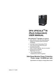
<strong>DPA</strong> <strong>UPSCALE</strong> TM <strong>ST</strong><br />
<strong>USER</strong> <strong>MANUAL</strong><br />
<strong>DPA</strong> <strong>UPSCALE</strong> TM highlights at a glance<br />
<strong>DPA</strong> UPScale with Safe-Swap Modules<br />
(SSM) For premium power protection<br />
availability<br />
Low total Cost of Ownership (TCO)<br />
Cost saving during entire life-cycle<br />
Flexibility/Scalability<br />
Ease of power upgrade, pay as you grow<br />
Enhanced Serviceability<br />
Rapid fault recovery<br />
Link to Newavewatch TM<br />
Instantaneous fault recognition<br />
Safe-Swap Modular Power Protection<br />
Power range: 10-120KW per rack<br />
Specifications are subject to change without notice
GENERAL CONTENTS OF THE<br />
<strong>USER</strong> <strong>MANUAL</strong> <strong>DPA</strong> <strong>UPSCALE</strong> TM <strong>ST</strong><br />
1 SECTION-1:<br />
1.2 MECHANICAL CHARACTERI<strong>ST</strong>ICS <strong>DPA</strong> <strong>UPSCALE</strong> <strong>ST</strong><br />
1.3 SAFETY IN<strong>ST</strong>RUCTIONS<br />
1.3.1 GENERAL SAFETY INTRODUCTION<br />
1.3.2 DESCRIPTION OF SYMBOLS USED IN THIS <strong>MANUAL</strong><br />
1.3.3 SYMBOLS, CONTROLS, AND INDICATORS<br />
1.3.4 OPERATOR PRECAUTIONS<br />
1.3.5 ENVIRONMENTAL CONSIDERATIONS<br />
1.3.6 DECLARATION OF SAFETY CONFORMITY AND CE MARKING<br />
1.3.7 INQUERIES<br />
1.4 SY<strong>ST</strong>EM DESCRIPTION<br />
1.4.1 GENERAL SY<strong>ST</strong>EM DESCRIPTION<br />
1.4.2 <strong>DPA</strong> <strong>UPSCALE</strong> <strong>ST</strong>TM BASIC SY<strong>ST</strong>EM CONFIGURATION<br />
1.4.3 QUALITY <strong>ST</strong>ANDARDS AND UPS CLASSIFICATION CODE<br />
1.4.4 SINGLE/PARALLEL-MODULES OPERATION<br />
1.4.5 WARRANTY<br />
1.4.6 EXTENDED WARRANTY<br />
1.5 DELVERY – TRANSPORT - <strong>ST</strong>ORAGE<br />
1.5.1 INTRODUCTION<br />
1.5.2 RECEIPT OF THE UPS AND VISUAL INSPECTION<br />
1.5.3 UNPACKING<br />
1.5.4 NAMEPLATE<br />
1.5.5 BATTERIES AND <strong>ST</strong>ORAGE<br />
1.6 SITE PLANNING AND POSITIONING<br />
1.6.1 PLANNING BEFORE THE IN<strong>ST</strong>ALLATION<br />
1.6.2 POSITIONING OF UPS AND BATTERY CABINET<br />
1.7 ELECTRICAL IN<strong>ST</strong>ALLATION<br />
1.7.1 PREPARATION FOR THE INPUT CABLING<br />
1.7.2 IN<strong>ST</strong>ALLATION CHECKLI<strong>ST</strong><br />
04-0314_CoverNEUTRAL_OPM<strong>DPA</strong>-UPScale_<strong>ST</strong>_GB_091101.doc Page 2/5<br />
Printed in Switzerland – Modifications reserved
2 SECTION-2:<br />
2.2 BLOCK DIAGRAM<br />
2.1.1 WIRING AND BLOCK DIAGRAMS FOR ALL FRAMES AND MODULES<br />
2.1.2 RECOMMENDED CABLE SECTIONS & FUSE RATINGS<br />
2.1.3 BLOCK DIAGRAM <strong>DPA</strong> <strong>UPSCALE</strong><br />
2.3 FRONT VIEW<br />
2.3.1 FRONT VIEW OF <strong>UPSCALE</strong> <strong>ST</strong> FRAMES<br />
2.4 BATTERY CONNECTIONS<br />
2.4.1 INTERNAL BATTERY MODULES<br />
2.4.2 EXTERNAL BATTERY CABINET AND BATTERY CONNECTION<br />
3 SECTION-3:<br />
3.2 INTERFACING<br />
3.2.1 CU<strong>ST</strong>OMER INTERFACE AND DRY PORTS (VOLT-FREE CONTACTS)<br />
3.2.2 JD1 / RS232 COMPUTER INTERFACE<br />
3.2.3 USB COMPUTER INTERFACE<br />
4 SECTION-4:<br />
4.2 OPERATION<br />
4.2.1 COMMISSIONING<br />
4.2.2 CONTROL PANEL<br />
4.2.3 DESCRIPTION OF THE LCD<br />
4.2.4 OPERATING MODES<br />
5 SECTION-5:<br />
5.2 OPERATION–PROCEDURES<br />
5.2.1 <strong>ST</strong>ART-UP PROCEDURE<br />
5.2.2 SHUTDOWN PROCEDURE<br />
5.2.3 LOAD TRANSFER: FROM INVERTER OPERATION TO MAINTENANCE BYPASS<br />
5.2.4 LOAD TRANSFER: FROM MAINTENANCE BYPASS TO INVERTER OPERATIONS<br />
5.3 REPLACEMENT OF UPS-MODULE<br />
5.3.1 REPLACEMENT OF UPS-MODULE IN SINGLE-MODULE SY<strong>ST</strong>EMS<br />
5.3.2 REPLACEMENT OF UPS-MODULE IN REDUNDANT MULTI-MODULE SY<strong>ST</strong>EM<br />
5.3.3 REPLACEMENT OF A MODULE IN CAPACITY MULTI-MODULE SY<strong>ST</strong>EM<br />
Section-0<br />
04-0314_CoverNEUTRAL_OPM<strong>DPA</strong>-UPScale_<strong>ST</strong>_GB_091101.doc Page 3/5<br />
Printed in Switzerland – Modifications reserved
6 SECTION-6:<br />
6.2 MULTI-CABINET CONFIGURATION (NOT AVAILABLE)<br />
7 SECTION-7:<br />
7.2 MAINTENANCE<br />
7.2.1 INTRODUCTION<br />
7.2.2 <strong>USER</strong> RESPONSIBILITIES<br />
7.2.3 ROUTINE MAINTENANCE<br />
7.2.4 BATTERY TE<strong>ST</strong><br />
7.2.5 BATTERY MAINTENANCE<br />
7.2.6 BATTERY DISPOSAL AND RECYCLING<br />
8 SECTION-8:<br />
8.2 TROUBLESHOOTING<br />
8.2.1 ALARMS<br />
8.2.2 MENU, COMMANDS, EVENT LOG, MEASUREMENTS,<br />
8.2.3 FAULT IDENTIFICATION AND RECTIFICATION<br />
9 SECTION-9:<br />
9.2 OPTIONS<br />
9.2.1 INTRODUCTION<br />
9.2.2 REMOTE SHUTDOWN (RSD)<br />
9.2.3 GENERATOR ON FACILITIES (GEN ON)<br />
9.2.4 WAVEMON SHUTDOWN AND MANAGEMENT SOFTWARE<br />
9.2.5 SNMP CARD/ADAPTER FOR NETWORK MANAGEMENT /REMOTE MONITORING<br />
9.2.6 MODEM/ETHERNET CARD / NEWAVEWATCH TM MANAGEMENT SOFTWARE<br />
Section-0<br />
04-0314_CoverNEUTRAL_OPM<strong>DPA</strong>-UPScale_<strong>ST</strong>_GB_091101.doc Page 4/5<br />
Printed in Switzerland – Modifications reserved
10 SECTION-10: TECHNICAL DATA SHEET<br />
10.2 <strong>DPA</strong> <strong>UPSCALE</strong> SY<strong>ST</strong>EM DESCRIPTION<br />
10.3 TECHNICAL CHARACTERI<strong>ST</strong>ICS <strong>DPA</strong> <strong>UPSCALE</strong> <strong>ST</strong><br />
10.3.1 MECHANICAL CHARACTERI<strong>ST</strong>ICS <strong>DPA</strong> <strong>UPSCALE</strong> <strong>ST</strong> FRAMES AND MODULES<br />
10.4 INPUT CHARACTERI<strong>ST</strong>ICS<br />
10.4.1 GRAPH: INPUT PF VERSUS % LOAD<br />
10.4.2 GRAPH: INPUT DI<strong>ST</strong>ORTION THDI VERSUS % LOAD<br />
10.5 BATTERY CHARACTERI<strong>ST</strong>ICS<br />
10.6 OUTPUT CHARACTERI<strong>ST</strong>ICS<br />
10.6.1 GRAPH: AC – AC EFFICIENCY WITH LINIER LOAD @ COSPHI 1<br />
10.6.2 GRAPH: OUTPUT POWER IN KW AND KVA VERSUS COSPHI<br />
10.7 ENVIRONMENTAL CHARACTERI<strong>ST</strong>ICS<br />
10.8 <strong>ST</strong>ANDARDS<br />
10.9 COMMUNICATION<br />
10.9.1 POWER MANAGEMENT DISPLAY (PMD)<br />
10.9.2 MIMIC DIAGRAM<br />
10.9.3 DISPLAY<br />
10.9.4 CU<strong>ST</strong>OMER INTERFACES TERMINALS X1…X2<br />
10.9.5 CU<strong>ST</strong>OMER INPUTS DRY PORT S: TERMINAL BLOCK X2<br />
10.9.6 CU<strong>ST</strong>OMER OUTPUTS DRY PORTS : TERMINAL BLOCKS X1<br />
10.10 OPTIONS<br />
10.10.1 MODEM/ETHERNET CARD / NEWAVEWATCHTM MANAGEMENT SOFTWARE<br />
10.10.2 SNMP CARD / WAVEMON MANAGEMENT SOFTWARE<br />
10.10.3 BATTERY CABINETS<br />
10.11 BATTERY AUTONOMIES<br />
10.11.1 EXAMPLES OF INTERNAL BATTERY AUTONOMY OF <strong>DPA</strong> <strong>UPSCALE</strong> <strong>ST</strong>40 AND <strong>ST</strong> 60<br />
10.11.2 EXAMPLES OF EXTERNAL BATTERY AUTONOMY<br />
10.12 IN<strong>ST</strong>ALLATION PLANNING<br />
10.12.1 HEAT DISSIPATION PER MODULE WITH NON-LINEAR LOAD<br />
10.13 WIRING AND BLOCK DIAGRAMS FOR ALL FRAMES AND MODULE<br />
10.13.1 TERMINAL CONNECTIONS OVERVIEW<br />
10.13.2 SINGLE FEED INPUT / CABLE SECTIONS<br />
10.13.3 SINGLE FEED INPUT<br />
10.13.4 DUAL FEED INPUT<br />
10.13.5 DUAL FEED INPUT / CABLE SECTIONS<br />
Section-0<br />
04-0314_CoverNEUTRAL_OPM<strong>DPA</strong>-UPScale_<strong>ST</strong>_GB_091101.doc Page 5/5<br />
Printed in Switzerland – Modifications reserved
CONTENTS SECTION-1<br />
1.1 MECHANICAL CHARACTERI<strong>ST</strong>ICS <strong>DPA</strong> <strong>UPSCALE</strong> <strong>ST</strong> ................................................................ 2<br />
1.2 SAFETY IN<strong>ST</strong>RUCTIONS................................................................................................................... 3<br />
1.2.1 GENERAL SAFETY INTRODUCTION........................................................................................ 3<br />
1.2.2 SYMBOLS, CONTROLS, AND INDICATORS ............................................................................ 3<br />
1.2.3 OPERATOR PRECAUTIONS...................................................................................................... 4<br />
1.2.4 ENVIRONMENTAL CONSIDERATIONS .................................................................................... 5<br />
1.2.5 DECLARATION OF SAFETY CONFORMITY AND CE MARKING ............................................ 5<br />
1.2.6 INQUIRIES................................................................................................................................... 5<br />
1.3 SY<strong>ST</strong>EM DESCRIPTION .................................................................................................................... 6<br />
1.3.1 GENERAL SY<strong>ST</strong>EM DESCRIPTION .......................................................................................... 6<br />
1.3.1.1 Feature : Unique “Safe-Swappable” Modules ..................................................................... 6<br />
1.3.1.2 Feature : Advanced-Booster Technology ............................................................................ 6<br />
1.3.1.3 Feature : Flexible Battery Management (FBM) ................................................................... 7<br />
1.3.1.4 Feature : <strong>DPA</strong> Technology - Decentralized Parallel Architecture....................................... 7<br />
1.3.2 <strong>DPA</strong> <strong>UPSCALE</strong> <strong>ST</strong> TM BASIC SY<strong>ST</strong>EM CONFIGURATION ...................................................... 8<br />
1.3.3 QUALITY <strong>ST</strong>ANDARDS AND UPS CLASSIFICATION CODE................................................... 8<br />
1.3.4 SINGLE/PARALLEL-MODULES OPERATION........................................................................... 9<br />
1.3.5 WARRANTY .............................................................................................................................. 10<br />
1.3.6 EXTENDED WARRANTY.......................................................................................................... 10<br />
1.4 DELIVERY – TRANSPORT - <strong>ST</strong>ORAGE ......................................................................................... 11<br />
1.4.1 INTRODUCTION ....................................................................................................................... 11<br />
1.4.2 RECEIPT OF THE UPS AND VISUAL INSPECTION............................................................... 11<br />
1.4.3 UNPACKING.............................................................................................................................. 12<br />
1.4.4 NAMEPLATE ............................................................................................................................. 13<br />
1.4.5 BATTERIES AND <strong>ST</strong>ORAGE.................................................................................................... 13<br />
1.4.5.1 Storage of battery ..............................................................................................................14<br />
1.4.5.2 Storage of UPS..................................................................................................................14<br />
1.5 SITE PLANNING AND POSITIONING ............................................................................................. 14<br />
1.5.1 PLANNING BEFORE THE IN<strong>ST</strong>ALLATION.............................................................................. 14<br />
1.5.2 POSITIONING OF UPS AND BATTERY CABINET.................................................................. 15<br />
1.5.2.1 Final Transport................................................................................................................... 15<br />
1.5.2.2 Positioning ......................................................................................................................... 15<br />
1.6 ELECTRICAL IN<strong>ST</strong>ALLATION.........................................................................................................16<br />
1.6.1 PREPARATION FOR THE INPUT CABLING ........................................................................... 17<br />
1.6.1.1 Mains supply and Earth connection................................................................................... 17<br />
1.6.1.2 Single Input Feed...............................................................................................................18<br />
1.6.1.3 Dual Input Feed .................................................................................................................18<br />
1.6.1.4 Preparation for the Output Cabling.................................................................................... 18<br />
1.6.1.5 Connection of the Load...................................................................................................... 19<br />
1.6.2 IN<strong>ST</strong>ALLATION CHECKLI<strong>ST</strong>.................................................................................................... 20<br />
Section-1<br />
04-0314_S1_NEUT_OPM_<strong>UPSCALE</strong>_<strong>ST</strong>_GB_091101.doc Page 1/20<br />
Printed in Switzerland – Modifications reserved
1.1 MECHANICAL CHARACTERI<strong>ST</strong>ICS <strong>DPA</strong> <strong>UPSCALE</strong> <strong>ST</strong><br />
Section-1<br />
<strong>DPA</strong> UPScale <strong>ST</strong> UPScale <strong>ST</strong> 40 UPScale <strong>ST</strong> 60 UPScale <strong>ST</strong> 80 UPScale <strong>ST</strong> 120<br />
<strong>DPA</strong> UPScale <strong>ST</strong> FRAMES<br />
Configuration<br />
accommodates:<br />
Max.<br />
2 module<br />
(10 or 20kW)<br />
and<br />
80 x 7/9Ah<br />
batteries<br />
3 modules<br />
(10 or 20kW)<br />
and<br />
240 x 7/9Ah<br />
batteries<br />
4 modules<br />
(10 or 20kW)<br />
and<br />
NO batteries<br />
6 modules<br />
(10 or 20kW)<br />
and<br />
NO batteries<br />
Max. Power connection kW 40 60 80 120<br />
Dimensions (WxHxD) mm 550x1135x770 550x1975x770 550x1135x770 550x1975x770<br />
Weight of Empty Frame<br />
w/o modules and<br />
w/o batteries<br />
Weight of Frame<br />
with modules and<br />
w/o batteries<br />
Colours<br />
MODULES<br />
Output Active Rated<br />
Power<br />
Variable Number of 12V<br />
Battery Blocks<br />
kg 92 173 82 133<br />
kg<br />
Dimensions (WxHxD) mm<br />
130 up to 136<br />
(with 2 Module)<br />
229 up to 238<br />
(with 3 Module)<br />
157up to 169<br />
(with 4 Modules)<br />
245 up to 263<br />
(with 6 Modules)<br />
Front : Graphite grey (Pulverlacke No. 4222903402 serie 09RCCAT1)<br />
Side walls: Graphite grey (Pulverlacke No. 4222903402 serie 09RCCAT1)<br />
UPScale M 10 UPScale M 20<br />
KW 10 20<br />
No. 20-50 *1) 30-50 *1)<br />
448 (488) x 132 x 540<br />
(3 HU)<br />
Weight UPS Module kg 18.6 21.5<br />
Colours Front : RAL 7016<br />
Note : * 1) Depending of the effective load in kW used by the module (see table Section 10, Chapter 10.5 Battery<br />
Characteristics)<br />
04-0314_S1_NEUT_OPM_<strong>UPSCALE</strong>_<strong>ST</strong>_GB_091101.doc Page 2/20<br />
Printed in Switzerland – Modifications reserved
1.2 SAFETY IN<strong>ST</strong>RUCTIONS<br />
Section-1<br />
1.2.1 GENERAL SAFETY INTRODUCTION<br />
The UPS System operates with mains, battery or bypass power. It contains components that carry high currents and<br />
voltages. The properly installed UPS System is grounded to earth and IP 20 rated against electrical shock and foreign<br />
objects. Installation and service have to be done by the manufacturer’s qualified technicians or their authorized service<br />
partners.<br />
WARNING! THERE IS DANGER OF AN ELECTRICAL IMPACT<br />
This user manual contains guidelines to check delivery, installing and commissioning of the UPS and is intended<br />
for people who plan the installation, install, commission and use or service the UPS. The reader is expected to<br />
know the fundamentals of electricity, wiring, electrical components and electrical schematic symbols<br />
!<br />
NOTE!<br />
1.2.2 SYMBOLS, CONTROLS, AND INDICATORS<br />
READ THE INFORMATION, IN ORDER TO AVOID EQUIPMENT<br />
DAMAGES<br />
PROTECTIVE GROUNDING TERMINAL<br />
A terminal which must be connected to earth ground prior to making any<br />
other connection to the equipment.<br />
A terminal to which or from which a direct current or voltage may be<br />
applied or supplied.<br />
This symbol indicates the word “phase”.<br />
ON The principal power switch is in the “ON” position<br />
OFF The principal power switch is in the “OFF” position.<br />
C<br />
St<br />
CAUTION: REFER TO <strong>MANUAL</strong><br />
Refer to the Operator’s Manual for more information<br />
DANGER: RISK OF ELECTRIC SHOCK<br />
There is a risk of electric shock present, and you should observe<br />
associated warnings. The UPS contains high voltages.<br />
04-0314_S1_NEUT_OPM_<strong>UPSCALE</strong>_<strong>ST</strong>_GB_091101.doc Page 3/20<br />
Printed in Switzerland – Modifications reserved
1.2.3 OPERATOR PRECAUTIONS<br />
The only user operations permitted are:<br />
• Use of the LCD control panel (LCD Display) and of the Maintenance Bypass<br />
• Start up and shut down of the UPS of the user field (excluding the commissioning start up)<br />
• Operation of additional connectivity modules:<br />
• SNMP adapters and their software<br />
Section-1<br />
• Modem/GSM or Modem/Ethernet adapters and their software<br />
The user must follow the precautions and only perform the described operations. Also in these measures the operator of<br />
the UPS System must adhere to the instructions in this manual. Any deviations from the instructions could be<br />
dangerous to the user or cause accidental load loss.<br />
NEWAVE SA DOES NOT TAKE ANY RESPONSIBILITY FOR DAMAGES CAUSED THROUGH WRONG<br />
MANIPULATIONS OF THE UPS SY<strong>ST</strong>EM.<br />
WARNING!<br />
WARNING!<br />
WARNING!<br />
IT IS PROHIBITED TO REMOVE ANY SCREWS FROM THE UPS SY<strong>ST</strong>EM OR<br />
FROM THE BATTERY CABINET. THERE IS A DANGER OF ELECTRICAL SHOCK.<br />
HIGH FAULT CURRENTS (LEAKAGE CURRENTS):<br />
BEFORE CONNECTING THE MAINS YOU MU<strong>ST</strong> ENSURE THAT THERE IS A<br />
PROPER EARTH CONNECTION!<br />
THE <strong>USER</strong> MU<strong>ST</strong> DISPLAY A WARNING SHIELD ON ALL PRIMARY UPS<br />
CIRCUIT BREAKERS. THE SERVICE PERSONNEL HAS TO BE INFORMED<br />
ABOUT DANGEROUS VOLTAGES. THE WARNING PANELS MU<strong>ST</strong> CONTAIN<br />
THE FOLLOWING TEXT: “ BEFORE <strong>ST</strong>ARTING WITH THE MAINTENANCE<br />
WORK ON THE CIRCUIT BREAKERS MAKE SURE THE UPS IS ISOLATED<br />
04-0314_S1_NEUT_OPM_<strong>UPSCALE</strong>_<strong>ST</strong>_GB_091101.doc Page 4/20<br />
Printed in Switzerland – Modifications reserved
Section-1<br />
1.2.4 ENVIRONMENTAL CONSIDERATIONS<br />
The UPS must be installed according to the recommendations in this manual. To operate the UPS at peak efficiency,<br />
your installation site should meet the environmental parameters outlined in this manual. Excessive amount of dust in the<br />
operating environment of UPS may cause damage or lead to malfunction. The UPS should be always protected from<br />
the outside weather and sunshine. If you intend to operate the system at an altitude higher than 1000 meters, contact<br />
your local sales or service office for important information about high altitude operation. The operating environment<br />
must meet the weight, airflow, size and clearance requirements specified in the technical datasheet.<br />
Under no circumstances the UPS should be installed in an airtight room, in the presence of flammable gases, or in an<br />
environment exceeding the specification.<br />
The basic environmental requirements of the UPS system are:<br />
• Ambient Temperature Range: 0 to +40˚C (32 – 104˚F)<br />
• Recommended Operating Range: +20 to +25˚C (68 – 77˚F)<br />
• Maximum Relative Humidity: 95% (non-condensing)<br />
The UPS cabinet uses forced air cooling to regulate internal component temperature. Air inlets are in the bottom sides<br />
and front of the cabinet, and outlets in the rear of the cabinet. You must allow clearance in back of the cabinet for<br />
proper air circulation. Refer to Section 1, 6.2.2 POSITIONING for clearance requirements.<br />
1.2.5 DECLARATION OF SAFETY CONFORMITY AND CE MARKING<br />
The product has the CE marking in compliance with the following European directives:<br />
• Low Voltage Directive: 2006/95/EC<br />
• EMC Directive: 2004/108/EC<br />
Declaration of conformity with UPS harmonized standards and directives EN 62040-1-1 (Safety)<br />
and EN 62040-2 (EMC) are available in the annex 1<br />
Safety Standard: IEC/EN 62040-1-1, IEC/EN 60950-1<br />
Electromagnetic<br />
Compatibility<br />
Standard (EMC)<br />
Performance Standard: IEC/EN 62040-3<br />
EN 61000-6-4 Prod.standard: EN 62040-2 limit A (C3 UPS)<br />
EN 61000-6-2 Prod.standard: EN 62040-2 Criterion A (C2 UPS)<br />
EN 61000-4-2 - EN 61000-4-3 - EN 61000-4-4 - EN 61000-4-5 - EN 61000-4-6<br />
1.2.6 INQUIRIES<br />
Address inquiries about the UPS and battery cabinet to the local office or agent authorized by the manufacturer.<br />
Please note the type code and the serial number of the equipment and contact your nearest agent authorized by the<br />
manufacturer (www.newaveups.com under Resellers).<br />
The Code and the serial no. are shown on the nameplate see Section 1, 1.5.4 Nameplate<br />
04-0314_S1_NEUT_OPM_<strong>UPSCALE</strong>_<strong>ST</strong>_GB_091101.doc Page 5/20<br />
Printed in Switzerland – Modifications reserved
1.3 SY<strong>ST</strong>EM DESCRIPTION<br />
Section-1<br />
The product described in this manual is a transformerless Uninterruptible Power System (UPS). It is a true online,<br />
continuous duty, double conversion, solid state, three-phase system, providing conditioned and uninterruptible AC<br />
power to protect the customer’s load from all nine power failures.<br />
1.3.1 GENERAL SY<strong>ST</strong>EM DESCRIPTION<br />
The UPS’s are used to protect sensitive equipment and prevent loss of valuable electronic information, minimise<br />
equipment downtime, and minimise the adverse effect on production equipment due to unexpected power problems.<br />
The UPS system continually monitors incoming electrical power and removes the surges, spikes, sags, and other<br />
irregularities that are inherent in commercial utility power. Working with a building‘s electrical system, the UPS system<br />
supplies clean, consistent power that sensitive electronic equipment requires for reliable operation. During brownouts,<br />
blackouts, and other power interruptions, batteries provide emergency power to safeguard operation.<br />
The UPS system is housed in single freestanding cabinets. The cabinets line up and match in style and colour, and<br />
have safety shields behind the doors for hazardous voltage protection.<br />
1.3.1.1 Feature : Unique “Safe-Swappable” Modules<br />
The unique Safe-Swappable feature of the Modules indicates the ability to insert and extract the electronic/power<br />
modules from a larger assembly while it is powered (hot). The safe-swappable design allows live powered modules to<br />
be attached to and removed from a powered set without causing disturbance to the operation of the load and without<br />
need to go to bypass.<br />
1.3.1.2 Feature : Advanced-Booster Technology<br />
Traditional input THD filters are no longer needed with this UPS product. The build-in advanced booster technology of<br />
UPS modules provides perfect sinusoidal input power quality at 0.99 input power factor with harmonic content less than<br />
3% THD(i). This leads to more reliable total system operation and savings in generator and transformer sizing as losses<br />
in the windings are minimised.<br />
Due to the active front booster, regulating each individual phase, the UPS is comparable to a clean resistor load (unity)<br />
from the mains perspective. Thus, the high input power factor provides minimised cabling and fusing costs due to no<br />
reactive power consumption. The low harmonic currents are due to high input power factor and provide the benefits:<br />
• No additional losses in wires and cables<br />
• No extra heating of transformers and generators with shortened service life<br />
• No over sizing of generators<br />
• No false circuit breaker tripping and malfunction<br />
• No erratic operation of computers, telecommunication, monitors, electronic test equipment etc.<br />
• No Resonance with power factor correction capacitors<br />
04-0314_S1_NEUT_OPM_<strong>UPSCALE</strong>_<strong>ST</strong>_GB_091101.doc Page 6/20<br />
Printed in Switzerland – Modifications reserved
Section-1<br />
1.3.1.3 Feature : Flexible Battery Management (FBM)<br />
The Flexible Battery Management (FBM) has been designed in all NEWAVE UPS products with the goal to avoid the<br />
deterioration of battery age. The FBM – Key Features protect the battery from environmental negative impacts (high<br />
temperature and false manipulations) and avoid deterioration of battery life by advanced management of battery<br />
charging and preventive failure diagnostics. The implemented features result in benefits not only for the end user, but<br />
also to the environment. The battery user will be required to replace his batteries less often. This translates into financial<br />
and environmental benefits. Last but not least a well protected and managed battery is a healthy battery and hence it<br />
enhance the overall availability of the UPS system.<br />
The major benefits are:<br />
• AC-Ripple free battery charging due to DC-DC charger separated from the rectifier and inverter<br />
• Wide range of number of battery blocks (30-50 blocks of 12V; depending autonomy times)<br />
• UPS’S wide input voltage window tolerance extends the battery life due to less discharge cycles<br />
• Battery discharge protection caused by load jumps<br />
• Proactive battery protection from false manipulations and inadequate charging voltages<br />
• Proactive battery failure detection thanks to Advanced Battery Diagnosis (ABD) - Algorithm<br />
• User selectable battery tests<br />
• Optional temperature compensated charging to enhance battery life<br />
Hence, the function of FBM system is to prolong the battery life considerably compared to traditional systems. In a<br />
traditional online UPS the inverter also causes ripple-current to be fed to batteries causing corrosion.<br />
1.3.1.4 Feature : <strong>DPA</strong> Technology - Decentralized Parallel Architecture<br />
The UPS product features <strong>DPA</strong> paralleling technology that provides N+X redundancy without introducing a single-pointof-failure.<br />
The products utilizing the <strong>DPA</strong> technology are completely autonomous be means of individual Power Units,<br />
Bypasses, CPU’s, Control Panels and separate battery configuration for each single module.<br />
The <strong>DPA</strong> technology makes it more reliable than traditional paralleling techniques. A parallel UPS system means the<br />
linking together of two or more UPS units in parallel so that in the unlikely event one fails the other can automatically<br />
take up the load. Traditionally a parallel redundancy configuration is achieved by having a random or fixed master-slave<br />
relationship among the UPS units. This master logic gives out individual commands to all the slaves units. Unfortunately<br />
this can lead to a single-point-of-failure for the whole system because if the master logic or communication to slaves<br />
fails, and causes the whole UPS system to be in trouble.<br />
The <strong>DPA</strong> technology was developed as a Multi-Master logic concept with separated independent regulation and logic<br />
buses to allow parallel capacity system and to maintain the highest system availability. An industry leading paralleling<br />
technology in its own right, the <strong>DPA</strong> technology enables you to set up a parallel redundant system giving you 100%<br />
conditioned power at all times. Its unique decentralized design eliminates the system level single point of failure inherent<br />
in traditional parallel UPS, and exponentially increases the reliability of the overall system.<br />
<strong>DPA</strong> UPScale <strong>ST</strong> technology allows up to six UPS modules to cover the same load in parallel and redundant<br />
configuration. No vulnerable master logic is needed in this design. It provides automatic load sharing and module level<br />
redundancy with nothing other than the power connecting to the <strong>DPA</strong> UPScale <strong>ST</strong> TM version of UPS modules.<br />
04-0314_S1_NEUT_OPM_<strong>UPSCALE</strong>_<strong>ST</strong>_GB_091101.doc Page 7/20<br />
Printed in Switzerland – Modifications reserved
Section-1<br />
1.3.2 <strong>DPA</strong> <strong>UPSCALE</strong> <strong>ST</strong> TM BASIC SY<strong>ST</strong>EM CONFIGURATION<br />
The UPS system is housed in single freestanding cabinets. The cabinets line up and match in style and colour,<br />
and have safety shields behind the doors for hazardous voltage protection.<br />
The following basic UPS systems configurations are available:<br />
<strong>DPA</strong> UPScale <strong>ST</strong>40 <strong>DPA</strong> UPScale <strong>ST</strong>60 <strong>DPA</strong> UPScale <strong>ST</strong>80 <strong>DPA</strong> UPScale <strong>ST</strong>120<br />
1.3.3 QUALITY <strong>ST</strong>ANDARDS AND UPS CLASSIFICATION CODE<br />
The <strong>DPA</strong> UPScale TM will provide your critical equipment with a steady and reliable power supply for many<br />
years.<br />
The unique and modular UPS <strong>DPA</strong> UPScale TM belongs to the newest generation of midrange 3-phase UPS-<br />
Systems. High reliability, low operating cost and excellent electrical performance are only some of the<br />
highlights of this innovative UPS solution.<br />
The criteria and methods implemented at NEWAVE SA for the design and manufacture correspond to the most<br />
stringent quality standards.<br />
NEWAVE is certified successfully in every areas according to the model of the International Standard<br />
ISO 9001/EN 29001. The Certification of UPS with the operating performance according to the Norm<br />
IEC 62 040-3 and VDE 0558 Part 530 is accomplished.<br />
With it the NEWAVE UPS has the Classification Code VFl-SS-111.<br />
Safety Standard: IEC/EN 62040-1-1, IEC/EN 60950-1<br />
Electromagnetic<br />
Compatibility<br />
Standard (EMC)<br />
Performance Standard: IEC/EN 62040-3<br />
EN 61000-6-4 Prod.standard: EN 62040-2 limit A (C3 UPS)<br />
EN 61000-6-2 Prod.standard: EN 62040-2 Criterion A (C2 UPS)<br />
EN 61000-4-2 - EN 61000-4-3 - EN 61000-4-4 - EN 61000-4-5 - EN 61000-4-6<br />
04-0314_S1_NEUT_OPM_<strong>UPSCALE</strong>_<strong>ST</strong>_GB_091101.doc Page 8/20<br />
Printed in Switzerland – Modifications reserved
1.3.4 SINGLE/PARALLEL-MODULES OPERATION<br />
The <strong>DPA</strong> UPScale TM has unique paralleling features. We distinguish: Single or Parallel-Modules<br />
A) Single-Module<br />
<strong>DPA</strong> UPScale <strong>ST</strong>40 <strong>DPA</strong> UPScale <strong>ST</strong>60 <strong>DPA</strong> UPScale <strong>ST</strong>80 <strong>DPA</strong> UPScale <strong>ST</strong>120<br />
Section-1<br />
If a configuration consists of one single Module it is defined as a Single-Module Configuration even being in different<br />
cabinets like UPScale <strong>ST</strong>-40 , UPScale <strong>ST</strong>-60 , UPScale <strong>ST</strong>-80 , UPScale <strong>ST</strong>-120 with a single Module.<br />
B) Parallel-Module:<br />
<strong>DPA</strong> UPScale <strong>ST</strong>-60<br />
A Parallel-Module is a Module that is operating in parallel with other equivalent Modules, but still within the same<br />
cabinet (e.g. <strong>DPA</strong>-UPScale <strong>ST</strong> 60) using the <strong>DPA</strong> technology<br />
04-0314_S1_NEUT_OPM_<strong>UPSCALE</strong>_<strong>ST</strong>_GB_091101.doc Page 9/20<br />
Printed in Switzerland – Modifications reserved
Section-1<br />
1.3.5 WARRANTY<br />
The UPS supplied is warranted against defects in design, materials for a period of twelve (12) months from its original<br />
date of commissioning or fifteen (15) months from the date of original delivery, whatever comes first, unless agreed<br />
differently between Newave and the partner or customer. Refer to 1.2.7 Extended warranty.<br />
Transportation cost of warranted material is not included in the warranty and has to be paid by the end-user.<br />
Do not return anything without written authorization from NEWAVE or your closest service centre. NEWAVE or the<br />
closest service centre will give you further instructions how to proceed.<br />
Any product must be returned to NEWAVE headquarter in Quartino with transportation charges prepaid and must be<br />
accompanied by a description of the failure. Products without description will not be handled.<br />
The warranty is invalidated, if the UPS has not been installed and/or commissioned by duly trained personnel of<br />
authorised subsidiaries or distributors.<br />
The warranty does not apply in any case of damage or loss caused by misuse, negligence, unauthorized repair or<br />
modification, incorrect installation and commissioning, inappropriate environmental conditions, accident, act of God or<br />
inappropriate application.<br />
If the UPS fails to conform to the above within the warranty period then NEWAVE SA or an authorized service centre<br />
will, at its sole option, repair or replace the UPS or parts of it. All repaired or replaced parts will remain the property of<br />
NEWAVE or of the authorized service centre.<br />
NEWAVE is not liable for any costs resulting from a failure, if the installation, commissioning, repair, alternation, or<br />
ambient conditions of the equipment do not fulfil the requirements specified in the documentation delivered with the unit<br />
and other relevant documentation, such as loss of profits or revenue, loss of equipment, loss of data or software, cost of<br />
substitutes, claims by third parties or otherwise.<br />
Under no circumstances shall NEWAVE, its suppliers or subcontractors be liable for special, indirect, incidental or<br />
consequential damages, losses or penalties. The technical data, information and specifications are valid at the time of<br />
printing. The UPS manufacturer reserves the right to modifications without prior notice.<br />
As general policy, NEWAVE does not recommend the use of any of its products in life support applications where failure<br />
or malfunction of the NEWAVE product can be reasonably expected to cause failure of the life support device or to<br />
significantly affect us safety or effectiveness. NEWAVE does not recommend the use of any of its products in direct<br />
patient care. NEWAVE will not knowingly sell its products for use in such applications unless it receives in writing<br />
assurances satisfactory to NEWAVE that the risks of injury or damage have been minimized, the customer assumes all<br />
such risks and the liability of NEWAVE is adequately protected under the circumstances.<br />
The UPS may contain batteries that must be re-charged for a minimum of 24 hours every 6 months to<br />
prevent deep discharging. Batteries that have been, for whatever reason, deep discharged are not covered<br />
by the warranty.<br />
1.3.6 EXTENDED WARRANTY<br />
The local office or distributor may grant a Extended Warranty period different to the above twelve (12) months and refer<br />
to local terms of liability as defined in the supply agreement or maintenance contract.<br />
For more details please contact the nearest local office or agent authorized by the manufacturer.<br />
(www.newaveups.com Resellers).<br />
04-0314_S1_NEUT_OPM_<strong>UPSCALE</strong>_<strong>ST</strong>_GB_091101.doc Page 10/20<br />
Printed in Switzerland – Modifications reserved
1.4 DELIVERY – TRANSPORT - <strong>ST</strong>ORAGE<br />
Section-1<br />
1.4.1 INTRODUCTION<br />
This chapter contains all the necessary information for the correct unpacking, positioning, cabling and installation of the<br />
UPS<br />
The UPS and accessories are delivered on a specifically designed pallet that is easy to move with a forklift or a pallet<br />
jack. Keep the UPS always in upright position and do not drop the equipment. Do not either stack the pallets because of<br />
high-energy batteries involved and the heavy weight<br />
!<br />
NOTE!<br />
IF THE UPS IS NOT IMMEDIATELY IN<strong>ST</strong>ALLED THE FOLLOWING GUIDELINES<br />
MU<strong>ST</strong> BE FOLLOWED:<br />
TRANSPORT:<br />
UPS CABINETS AND/OR BATTERY CABINET CAN FALL OVER. USE THE<br />
SHIPPING BRACKETS ON THE REAR AND FRONT TO SECURE THE<br />
CABINETS. DO NOT TILT THEM MORE THAN 10° FROM VERTICAL,<br />
OTHERWISE CABINETS MAY TIP OVER.<br />
POTENTIAL DANGERS:<br />
- TILTING THE CABINET MIGHT DAMAGE THE SY<strong>ST</strong>EM AND THEREFORE<br />
SHOULD NO LONGER BE CONNECTED TO THE MAINS.<br />
- WEIGHT OF THE UPS SY<strong>ST</strong>EM COULD CAUSE SERIOUS INJURIES TO<br />
PERSONS OR ANYTHING IN THE SURROUNDING AREA.<br />
<strong>ST</strong>ORAGE:<br />
- THE UPS SHOULD BE <strong>ST</strong>ORED IN THE ORIGINAL PACKING AND<br />
SHIPPING CARTON<br />
- THE RECOMMENDED <strong>ST</strong>ORING TEMPERATURE FOR THE UPS SY<strong>ST</strong>EM<br />
AND BATTERIES IS BETWEEN +5 °C AND +40°C.<br />
- THE UPS SY<strong>ST</strong>EM AND THE BATTERIE SETS MU<strong>ST</strong> BE PROTECTED<br />
FROM HUMIDITY < 90% RF (NON-CONDENSING)<br />
1.4.2 RECEIPT OF THE UPS AND VISUAL INSPECTION<br />
Open receiving the UPS, carefully examine the packing container and the UPS for any sign of physical damage.<br />
The outside ’Tip&Tel’ ( "FRAGILE" and "ARROW") indicator should be intact if the equipment has been transported<br />
in the upright position. In case of rupture or suspect inform immediately:<br />
• The carrier and<br />
• NEWAVE SA.<br />
Ensure that the received UPS corresponds to the material indicated in the delivery note.<br />
The packing container of the UPS protects it from mechanical and environmental damage. To increase its<br />
protection the UPS is wrapped with a plastic sheet.<br />
!<br />
NOTE!<br />
VISIBLE TRANSPORT DAMAGES MU<strong>ST</strong> BE CLAIMED TO THE CARRIER<br />
IMMEDIATELY AFTER RECEIPT !!<br />
OTHER CLAIM FOR SHIPPING DAMAGE MU<strong>ST</strong> BE FILED IMMEDIATELY TOO<br />
AND THE CARRIER MU<strong>ST</strong> BE INFORMED WITHIN 7 DAYS OF RECEIPT OF THE<br />
EQUIPMENT. THE PACKING MATERIALS SHOULD BE <strong>ST</strong>ORED FOR FURTHER<br />
INVE<strong>ST</strong>IGATION.<br />
04-0314_S1_NEUT_OPM_<strong>UPSCALE</strong>_<strong>ST</strong>_GB_091101.doc Page 11/20<br />
Printed in Switzerland – Modifications reserved
Section-1<br />
1.4.3 UNPACKING<br />
Unpack the equipment by removing the packing and shipping materials. Make a visual inspection and check that<br />
’Tip&Tel’ indicator ( "FRAGILE" and "ARROW") on the packing container is intact.<br />
Perform the following steps to unpack the UPS equipment from the pallet and make sure that the floor surface is solid<br />
and suitable for the wheeling and heavy weight:<br />
(1) Cut wrappers and remove packing container by pulling it upwards (attention, on the top of the UPS<br />
inside the packing there is another carton box containing the accessories and user manual);<br />
(2) Remove the plastic cover from the UPS;<br />
(3) Remove pallet from the UPS;<br />
• Retain the packaging materials for future shipment of the UPS;<br />
!<br />
KG<br />
• Examine the UPS for any sign of damage. Notify your carrier or supplier immediately if damage is<br />
apparent.<br />
(4a) Open the UPS-door and make sure that all the UPS-Modules are appropriately fitted in their UPS-<br />
Compartment and if the UPS system is provided<br />
(4b) Without a UPS-module make sure that the empty UPS-compartment is correctly covered with the UPScompartment<br />
protection cover.<br />
HEAVY !<br />
1<br />
4<br />
04-0314_S1_NEUT_OPM_<strong>UPSCALE</strong>_<strong>ST</strong>_GB_091101.doc Page 12/20<br />
Printed in Switzerland – Modifications reserved<br />
3<br />
2
By unpacking the equipment from the wooden case remove all screws.<br />
Bottom screws Sides screws<br />
Section-1<br />
1.4.4 NAMEPLATE<br />
The technical specifications of the Equipment are provided on the nameplate, which is situated at the front of the UPS.<br />
Check if it corresponds to the purchased material mentioned in the delivery note.<br />
1.4.5 BATTERIES AND <strong>ST</strong>ORAGE<br />
The standard batteries of the UPS are sealed, maintenance-free batteries, mounted usually in an external battery<br />
cabinet and will typically be connected when the UPS is commissioned.<br />
The battery life depends very much on the ambient temperature. A temperature range between +18° and +23°C will<br />
achieve the optimum battery life.<br />
If the UPS is delivered without batteries, NEWAVE is not responsible for any damage or malfunctioning caused to the<br />
UPS by incorrect wiring.<br />
!<br />
KG<br />
HEAVY !<br />
04-0314_S1_NEUT_OPM_<strong>UPSCALE</strong>_<strong>ST</strong>_GB_091101.doc Page 13/20<br />
Printed in Switzerland – Modifications reserved
Section-1<br />
1.4.5.1 Storage of battery<br />
The battery life depends very much on the ambient temperature. It is therefore important not to store the battery longer<br />
than 6 months at 20°C, 3 months at 30°C and 2 months at 35°C storage temperature without a battery recharge. For<br />
long-term storage make sure that the battery is fully recharged every 6 months. Before and after storing, charge the<br />
battery.<br />
Always store the batteries in a dry, clean, cool environment in their original packaging. If the packing container is<br />
removed protect the batteries from dust and humidity.<br />
SEALED BATTERIES MU<strong>ST</strong> NEVER BE <strong>ST</strong>ORED IN A DISCHARGED OR<br />
PARTIALLY DISCHARGED <strong>ST</strong>ATE.<br />
EXTREME TEMPERATURE, UNDER- AND OVERCHARGE AND<br />
OVERDISCHARGE WILL DE<strong>ST</strong>ROY BATTERIES!<br />
WARNING!<br />
1.4.5.2 Storage of UPS<br />
If you plan to store the UPS prior to use, keep the UPS unpacked in a dry, clean and cool storage room with an ambient<br />
temperature between (+5 °C to +40°C) and humidity of less than 90%.<br />
If the packing container is removed protect the UPS from dust.<br />
!<br />
NOTE!<br />
1.5 SITE PLANNING AND POSITIONING<br />
THE UPS SY<strong>ST</strong>EM, THE BATTERY CABINET AND THE BATTERIES ARE HEAVY<br />
AND MAY TIP DURING TRANSPORTATION CAUSING SERIOUS INJURY IF<br />
UNPACKING IN<strong>ST</strong>RUCTIONS ARE NOT CLOSELY FOLLOWED.<br />
1.5.1 PLANNING BEFORE THE IN<strong>ST</strong>ALLATION<br />
The equipment must be installed and transported in a upright position. The equipment requires space to bottom/front<br />
and back to enable cooling airflow. It is required to arrange ventilation of the UPS room.<br />
All parts of the UPS for service and user access are accessible from the front and rear, making it a service-friendly and<br />
maintenance-friendly UPS. Reserve enough space from the front (min. 600 mm)<br />
The UPS should be located where:<br />
• Humidity (< 90 % non-condensing) and temperature (+15° and +25°C ) are within prescribed limits<br />
• Fire protection standards are respected<br />
• Cabling can be performed easily<br />
• Available front accessibility for service or periodic maintenance<br />
• Requested air cooling flow should be granted<br />
• The air conditioning system should have sufficient amount of air cooling needed to keep the max. room<br />
temperature rise at desired level:<br />
• Dust or corrosive/explosive gases must be absent<br />
• The place is vibration free<br />
• Only front access is necessary for service and maintenance.<br />
• If the UPS will be installed in bayed enclosures, partition walls have to be installed as well.<br />
An ambient temperature of 15 to 25 Celsius degrees is recommended to achieve a long life of the UPS and batteries.<br />
The cooling air entering the UPS must not exceed +40 °C. Avoid high ambient temperature, moisture and humidity. The<br />
floor material should be non-flammable and strong enough to support the heavy load.<br />
04-0314_S1_NEUT_OPM_<strong>UPSCALE</strong>_<strong>ST</strong>_GB_091101.doc Page 14/20<br />
Printed in Switzerland – Modifications reserved
Section-1<br />
1.5.2 POSITIONING OF UPS AND BATTERY CABINET<br />
1.5.2.1 Final Transport<br />
Check before transporting the surface loading and use a adequate forklift to move the equipment to the final position.<br />
Weights see section 1 on pages 2 and 3<br />
! HEAVY !<br />
KG<br />
Fig. 3.6.3 Floor surface must<br />
support loading<br />
1.5.2.2 Positioning<br />
UPS : A minimum 20 cm rear space from the UPS to an obstruction is recommended for proper cooling as the air<br />
enters at bottom/front and exits at unit rear (see Fig. 1 and 2)<br />
External Battery : If external battery are needed it is recommended to install external battery cabinet(s) next to the<br />
UPS unit. The external battery can be placed on either side of the UPS unit, but it is recommended to install on left<br />
hand side.<br />
Check before the installation that the battery voltage values in the ID card of in the Display settings of the UPS and<br />
external battery cabinets are the same.<br />
WARNING!<br />
WARNING!<br />
THE UPS CONTAINS HIGH DC VOLTAGES. A QUALIFIED PERSON MU<strong>ST</strong> DO<br />
THE CONNECTIONS BETWEEN THE UPS AND THE EXTERNAL BATTERY<br />
CABINET(S). THE BATTERY CABINET IS CONNECTED ELECTRICALLY IN<br />
PARALLEL WITH THE INTERNAL BATTERIES OF THE UPS.<br />
IF AVAILABLE, THE INTERNAL BATTERY HAS TO BE DISCONNECTED<br />
FIR<strong>ST</strong> BECAUSE THE EXTERNAL<br />
BATTERY TERMINALS ARE HAZARDOUS DUE TO THE PARALLEL<br />
BATTERY <strong>ST</strong>RING.<br />
Battery Racks : External battery racks shall be sized to take the voltage drop in the cable into account. To obtain<br />
support and help contact the local office or agent authorized by the manufacturer.<br />
Clearances X Y<br />
Minimum 200mm 900 mm<br />
X<br />
UPS<br />
Frames<br />
Open Doors<br />
Y<br />
Battery<br />
Cabinet<br />
UPS<br />
Frames<br />
Figure 1: UPS space recommendation Figure 2 : : UPS + Battery space recommendation<br />
04-0314_S1_NEUT_OPM_<strong>UPSCALE</strong>_<strong>ST</strong>_GB_091101.doc Page 15/20<br />
Printed in Switzerland – Modifications reserved<br />
X<br />
Open Doors Y
1.6 ELECTRICAL IN<strong>ST</strong>ALLATION<br />
Section-1<br />
The customer has to supply the wiring to connect the UPS to the local power source see Section 2, chapter 1.1.<br />
The electrical installation procedure is described in the following text. The installation inspection and initial start up<br />
of the UPS and extra battery cabinet must be carried out by a qualified service personnel such as a licensed<br />
service engineer from the manufacturer or from an agent authorised by the manufacturer.<br />
WARNING!<br />
WARNING!<br />
THE IN<strong>ST</strong>RUCTION IN THIS <strong>USER</strong> <strong>MANUAL</strong> HAVE ALWAYS TO BE FOLLOWED<br />
IN ORDER TO AVOID INJURIES FROM ELECTRICAL IMPACTS.<br />
ALL THE OPERATIONS IN THIS <strong>MANUAL</strong> MU<strong>ST</strong> BE PERFORMED BY<br />
AUTHORISED ELECTRICIANS OR BY QUALIFIED INTERNAL PERSONNEL.<br />
DO NOT OPERATE IN CASE OF PRESENCE OF WATER OR MOI<strong>ST</strong>URE.<br />
BY OPENING OR REMOVING THE UPS-COVERS YOU RUN RISK OF<br />
EXPOSURE TO DANGEROUS VOLTAGES<br />
PHYSICAL INJURY OR DEATH MAY FOLLOW, OR DAMAGE MAY OCCUR TO<br />
THE UPS, OR THE LOAD EQUIPMENT IF THESE IN<strong>ST</strong>RUCTIONS ARE<br />
IGNORED.<br />
To ensure correct operation of the UPS and its ancillary equipment it is necessary to provide the mains cables with<br />
appropriate fuse protection. See Section 2, chapter 2.1.2<br />
The UPS unit has the following power connections:<br />
Rectifier (In) : Three-phase (1L1, 1L2, 1L3), Neutral (1N) and protective earth (PE)<br />
connection for the rectifier input<br />
Bypass (In) : Three-phase (2L1, 2L2, 2L3), Neutral (2N)<br />
connection for the bypass if used as Dual Feed input<br />
Load (Out) : Three-phase (3L1, 3L2, 3L3), Neutral (3N) and protective earth (PE)<br />
connection for the load output<br />
External Battery : Plus (+), Common (N), Minus (-) and protective earth (PE)<br />
connection for the external batteries<br />
!<br />
NOTE!<br />
INPUT NEUTRAL IS REQUIRED TO OPERATE THE RECTIFIER.<br />
In TN-S Systems, no 4-pole input switches or circuit breakers should be used.<br />
(Grounding of Neutral during battery operation).<br />
UPS<br />
0V 230V<br />
04-0314_S1_NEUT_OPM_<strong>UPSCALE</strong>_<strong>ST</strong>_GB_091101.doc Page 16/20<br />
Printed in Switzerland – Modifications reserved
1.6.1 PREPARATION FOR THE INPUT CABLING<br />
!<br />
NOTE!<br />
Section-1<br />
Before proceeding read the chapter ELECTRICAL IN<strong>ST</strong>ALLATION<br />
(SECTION 1) and insure before starting connecting the cable to the UPS that:<br />
• Mains voltage (INPUT VOLTS) and frequency (FREQUENCY) correspond to the values indicated on<br />
the Nameplate of the UPS.<br />
• Earth connection is performed in accordance with the prescribed IEC Standards or with local<br />
regulations;<br />
• UPS is connected to the mains through a Low Voltage (LV)-Distribution Board with a separate mains<br />
line (protected with a circuit breaker or fuse) for the UPS.<br />
Provide input fuses and cables according to Section 2, chapter 2.1.2 or in accordance with the prescribed IEC<br />
Standards or with the local regulations.<br />
The input of the UPS must be fitted with circuit breakers or other kind of protection. The circuit breakers will be<br />
connected between the mains supply and the UPS and will provide additional protection to the UPS in the event of<br />
overloads and short circuits.<br />
1.6.1.1 Mains supply and Earth connection<br />
To ensure protection of personnel during the installation of UPS make sure that the connections are performed under<br />
the following conditions:<br />
• No mains voltage is present<br />
• All Loads are shut down and disconnected<br />
• UPS is shut down and voltage-free<br />
• UPS-Module is fitted in its correct position<br />
• Maintenance Bypass IA1 is open and in position OFF;<br />
• Remove Terminal cover of the UPS<br />
1. Connect first the Earthing wire coming from the Low Voltage-Distribution Board to the terminal "PE".<br />
2. Connect the input power cable coming from the Low Voltage-Distribution Board to the terminals of the<br />
UPS showed in Section 2, chapter 2.1.2<br />
3. Keep the phase rotation in clock-wise sense.<br />
!<br />
NOTE!<br />
INPUT NEUTRAL IS REQUIRED TO OPERATE THE RECTIFIER.<br />
Under the connection terminal of the UPS there is a cable-fixing rail to ensure that the cables have been fastened<br />
properly.<br />
NOTE: The UPS is provided with facilities for both single feed (one common input cable for rectifier<br />
and bypass) and dual feed (separate input cable for rectifier and bypass).<br />
04-0314_S1_NEUT_OPM_<strong>UPSCALE</strong>_<strong>ST</strong>_GB_091101.doc Page 17/20<br />
Printed in Switzerland – Modifications reserved
Section-1<br />
1.6.1.2 Single Input Feed<br />
To achieve correct Input Cabling see Drawing Section 2, chapter 2.1.2<br />
For single input feed connect the mains input cable to UPS Terminal Block according to the following table:<br />
MAINS INPUT CABLE UPS TERMINAL<br />
Phase L1 1L1<br />
Phase L2 1L2<br />
Phase L3 1L3<br />
NEUTRAL 1N<br />
EARTH PE<br />
For minimum recommended Input Cable Sections and Fuse Ratings Section 2, chapter 2.1.2<br />
Under the connection terminal of the UPS there is a cable-fixing rail to ensure that the cables have been fastened<br />
properly.<br />
1.6.1.3 Dual Input Feed<br />
To achieve correct input cabling see Terminal Block in Section 2, chapter 2.1.2<br />
NOTE: The UPS is supplied (as standard version) with facilities for a single cable feed (for rectifier and bypass).<br />
If dual feed is required unscrew the terminal bridges between (L1,L2,L3, only)<br />
UPS TERMINAL UPS TERMINAL<br />
Rectifier<br />
Bypass<br />
1L1 2L1<br />
1L2 2L2<br />
1L3 2L3<br />
1N<br />
PE<br />
2N<br />
For dual input feed connect the mains input cables to UPS Terminal according to following tables:<br />
MAINS INPUT CABLE UPS TERMINAL BYPASS INPUT CABLE UPS TERMINAL<br />
Rectifier<br />
Bypass<br />
Phase L1 1L1 Phase L1 2L1<br />
Phase L2 1L2 Phase L2 2L2<br />
Phase L3 1L3 Phase L3 2L3<br />
NEUTRAL 1N NEUTRAL 2N<br />
EARTH PE<br />
For minimum recommended Input Cable Sections and Fuse Ratings Section 2, chapter 2.1.2<br />
Under the connection terminal of the UPS there is a cable-fixing rail to ensure that the cables have been fastened<br />
properly.<br />
1.6.1.4 Preparation for the Output Cabling<br />
Before you start connecting the loads, ensure that the sum of the indicated UPS-module rated powers (OUTPUT<br />
POWER) on the nameplates (on the front side of the UPS-modules) is equal to or larger than the total load<br />
requirements.<br />
The output of the UPS must be fitted with circuit breakers or other kind of protection. These circuit breakers will be<br />
connected between the loads and the UPS and will provide additional protection to the UPS in the event of overloads<br />
and short circuits.<br />
These circuit breakers will enable the protection of each load separately.<br />
The size of the circuit breakers depends on the load rating of the load sockets.<br />
The circuit breakers must comply with the prescribed IEC Standards. It is recommended to provide a separate output<br />
distribution board for the load.<br />
04-0314_S1_NEUT_OPM_<strong>UPSCALE</strong>_<strong>ST</strong>_GB_091101.doc Page 18/20<br />
Printed in Switzerland – Modifications reserved
Section-1<br />
The following values should be indicated on the output distribution board:<br />
Maximum total load rating;<br />
Maximum load rating of the load sockets.<br />
If a common distribution board is used (sockets for Mains and UPS voltage), ensure that on each socket there is an<br />
indication of the applied voltage (“Mains” or “UPS”).<br />
Output power cable ratings should be in accordance with the recommended cable sections and fuses ratings or in<br />
accordance with the prescribed IEC Standards or with the local regulations.<br />
Under the connection terminal of the UPS there is a cable-fixing rail to ensure that the cables have been fastened<br />
properly.<br />
Ensure that the earthing is performed in accordance with the prescribed IEC Standards or with the local regulations.<br />
1.6.1.5 Connection of the Load<br />
To ensure protection of the personnel during the installation of the UPS make sure that the connections are performed<br />
under the following conditions:<br />
No mains voltage is present;<br />
All loads are shut down and disconnected;<br />
PMC is shut down and voltage-free.<br />
Before connecting the output power cables make sure that:<br />
UPS-Module is fitted in its correct position;<br />
Maintenance bypass is in position OFF;<br />
Remove the terminal cover of the UPS.<br />
Connect the output power cable coming from the LV-Distribution Board to the terminals of the UPS as shown in drawing<br />
in Section 2 / Chapter 2 (Front view of the <strong>DPA</strong> UPScale TM ’s)<br />
04-0314_S1_NEUT_OPM_<strong>UPSCALE</strong>_<strong>ST</strong>_GB_091101.doc Page 19/20<br />
Printed in Switzerland – Modifications reserved
1.6.2 IN<strong>ST</strong>ALLATION CHECKLI<strong>ST</strong><br />
All packing materials and restraints have been removed from each cabinet.<br />
Each cabinet in the UPS system is placed in the installed location.<br />
All conduits and cables are properly routed to the UPS and auxiliary cabinets.<br />
All power cables are properly sized and terminated.<br />
A ground conductor is properly installed.<br />
Section-1<br />
If the cabinet does not use all module mounting locations, the provided protective covers<br />
are installed on the front and back of the cabinet.<br />
Battery cabinet installation instructions have been completed.<br />
Air conditioning equipment is installed and operating properly.<br />
The area around the installed UPS system is clean and dust-free. (It is recommended that<br />
the UPS be installed on a level floor suitable for computer or electronic equipment.<br />
Adequate workspace exists around the UPS and other cabinets.<br />
Adequate lighting is provided around all UPS equipment.<br />
Any optional accessories are mounted in their installed location and properly wired.<br />
Summary alarms and/or building alarms are wired appropriately. (OPTIONAL)<br />
Startup and operational checks performed by authorized service personnel.<br />
All network connections are completed.<br />
04-0314_S1_NEUT_OPM_<strong>UPSCALE</strong>_<strong>ST</strong>_GB_091101.doc Page 20/20<br />
Printed in Switzerland – Modifications reserved
CONTENTS SECTION-2<br />
Section-2<br />
2.1 BLOCK DIAGRAM.......................................................................................................................2<br />
2.1.1 WIRING AND BLOCK DIAGRAMS FOR ALL FRAMES AND MODULES...........................2<br />
2.1.2 RECOMMENDED CABLE SECTIONS & FUSE RATINGS ..................................................2<br />
2.1.2.1 Terminal connections overview......................................................................................2<br />
2.1.3 BLOCK DIAGRAM <strong>DPA</strong> <strong>UPSCALE</strong>...................................................................................3<br />
2.1.3.1 Single Feed input (Standard Version) ............................................................................3<br />
2.1.3.2 SINGLE FEED INPUT / Cable Sections ........................................................................3<br />
2.1.3.3 Dual feed input (Optional Version) .................................................................................4<br />
2.1.3.4 Dual FEED INPUT / Cable Sections ..............................................................................4<br />
2.2 FRONT VIEW ...............................................................................................................................5<br />
2.2.1 FRONT VIEW <strong>UPSCALE</strong> <strong>ST</strong> 40 AND CONNECTION TERMINALS ....................................5<br />
2.2.2 FRONT VIEW <strong>UPSCALE</strong> <strong>ST</strong> 60 AND CONNECTION TERMINALS ....................................6<br />
2.2.3 FRONT VIEW <strong>UPSCALE</strong> <strong>ST</strong> 80 AND CONNECTION TERMINALS ....................................7<br />
2.2.4 FRONT VIEW <strong>UPSCALE</strong> <strong>ST</strong> 120 AND CONNECTION TERMINALS ..................................8<br />
2.3 BATTERY CONNECTIONS .........................................................................................................9<br />
2.3.1 INTERNAL BATTERY MODULES ........................................................................................9<br />
2.3.1.1 Internal Battery Modules <strong>DPA</strong> UPScale <strong>ST</strong> 40 ..............................................................9<br />
2.3.1.2 Internal Battery Modules <strong>DPA</strong> UPScale <strong>ST</strong> 60 ............................................................10<br />
2.3.2 EXTERNAL BATTERY CABINET AND BATTERY CONNECTION....................................11<br />
2.3.2.1 External Battery Configuration .....................................................................................11<br />
2.3.2.2 Connection of External Battery Cabinet for <strong>DPA</strong> UPScale.......................................13<br />
2.3.2.3 Connection of External Separate Battery for <strong>DPA</strong> UPScale TM .....................................14<br />
2.3.2.4 Connection of External Common Battery for <strong>DPA</strong> UPScale TM .....................................14<br />
04-0314_S2_NEUT_OPM_<strong>UPSCALE</strong>_<strong>ST</strong>_GB_091101.doc Page 1/14<br />
Printed in Switzerland – Modifications reserved
2.1 BLOCK DIAGRAM<br />
2.1.1 WIRING AND BLOCK DIAGRAMS FOR ALL FRAMES AND MODULES<br />
Section-2<br />
The customer has to supply the wiring to connect the UPS to the local power source. The installation inspection<br />
and initial start up of the UPS and extra battery cabinet must be carried out by a qualified service personnel<br />
such as a licensed service engineer from the manufacturer or from an agent authorized by the manufacturer.<br />
2.1.2 RECOMMENDED CABLE SECTIONS & FUSE RATINGS<br />
2.1.2.1 Terminal connections overview<br />
FRAME TYPE<br />
Terminals (T)<br />
Connection Bar (B)<br />
Battery Earth<br />
PE<br />
UPScale <strong>ST</strong> 40 16/25mm 2 (T)<br />
UPScale <strong>ST</strong> 60 50 mm 2 (T)<br />
UPScale <strong>ST</strong> 80 50 mm 2 (T)<br />
UPScale <strong>ST</strong> 120 50 mm 2 (T)<br />
UPScale <strong>ST</strong> 40<br />
Batt. Input Output<br />
UPScale <strong>ST</strong> 80<br />
Batt. Input Output<br />
Separate. Battery<br />
(+ / N / - )<br />
2x<br />
(3 x 10/16mm 2 ) (T)<br />
3x<br />
3 x 10/16mm 2 ) (T)<br />
4x<br />
(3 x 10/16mm 2 ) (T)<br />
6x<br />
(3 x 10/16mm 2 ) (T)<br />
Common<br />
Battery<br />
(+ / N / - )<br />
Input Bypass<br />
3+N<br />
Input Rectifier<br />
3+N+PE<br />
Output load<br />
3+N+PE<br />
3 x M5 (B) 4 x 16/25 mm 2 (T) 5 x 16/25 mm 2 (T) 5 x 16/25 mm 2 (T)<br />
3 x M6 (B) 4 x 35 mm 2 (T)<br />
3 x M6 (B)<br />
3 x 2xM5 (B)<br />
or<br />
3 x M10 (B)<br />
3 x 50 mm 2 (T)<br />
+ N 70/95 mm 2<br />
(T)<br />
4 x 70/95mm 2 (T)<br />
UPScale <strong>ST</strong> 60<br />
Batt. Input Output<br />
UPScale <strong>ST</strong> 120<br />
4 x 35 mm 2 (T)<br />
+PE 50/70 mm 2 (T)<br />
3 x 50 mm 2 (T)<br />
+ N 70/95 mm 2 (T)<br />
+PE 50 mm 2 (T)<br />
4 x 70/95mm 2 (T)<br />
+PE 50 mm 2 (T)<br />
Batt. Input Output<br />
4 x 35 mm 2 (T)<br />
+PE 50 mm 2 (T)<br />
3 x 50 mm 2 (T)<br />
+ N 70/95 mm 2 (T)<br />
+PE 50 mm 2 (T)<br />
4 x 70/95mm 2 (T)<br />
+PE 50 mm 2 (T)<br />
04-0314_S2_NEUT_OPM_<strong>UPSCALE</strong>_<strong>ST</strong>_GB_091101.doc Page 2/14<br />
Printed in Switzerland – Modifications reserved
2.1.3 BLOCK DIAGRAM <strong>DPA</strong> <strong>UPSCALE</strong><br />
2.1.3.1 Single Feed input (Standard Version)<br />
Cable Sections and Fuse Ratings recommended. Alternatively, local standards to be respected<br />
Frame<br />
type<br />
Cable E<br />
Fuse<br />
E<br />
Frame<br />
Fuse<br />
Cable A<br />
F1 F2<br />
Rectifier<br />
Inverter<br />
Static Switch<br />
2.1.3.2 SINGLE FEED INPUT / Cable Sections<br />
Input 3x400V/230V<br />
Load<br />
in KW Fuse A<br />
(Agl/CB)<br />
UPS module 1<br />
MAINS 3x400/230V<br />
Cable A<br />
(mm 2 )<br />
(IEC 60950-<br />
1:2001)<br />
F1 F2<br />
Rectifier<br />
Inverter<br />
Static Switch<br />
Cable D<br />
UPS module 2…4<br />
Maintenance Bypass IA1<br />
Load 3x400/230 V<br />
Max. Input Current<br />
with battery<br />
charging [A]<br />
<strong>ST</strong>ANDARD VERSION (SINGLE FEED INPUT)<br />
Output 3x400V/230V<br />
@ cosphi 1.0<br />
Cable D<br />
(mm 2 )<br />
(IEC 60950-<br />
1:2001)<br />
I nom<br />
[A]<br />
Battery<br />
Fuse E<br />
+ / N / -<br />
(Agl/CB)<br />
Section-2<br />
Cable E (mm 2 )<br />
for CBAT UPScale 120 or<br />
200 ONLY<br />
+ / N / -<br />
Com.<br />
Battery<br />
Sep. Battery<br />
UPScale <strong>ST</strong> 40 40 3x80A 5x16 68 A 5x16 58 A 3x100A *1 3x25 *1 2x(3x10)<br />
UPScale <strong>ST</strong> 60 60 3x125A 5x35 102 A 5x35 87 A 3x160A*1 3x50 *1 3x (3x10)<br />
UPScale <strong>ST</strong> 80 80 3x160A 5x50 136 A 5x50 116 A 3x224A*1 3x95 *1 4x (3x10)<br />
UPScale <strong>ST</strong>120 120 3x224A 5x95 208 A 5x70 174 A 3x300A*1 3x150 *1 6x (3x10)<br />
F1 F2<br />
Rectifier<br />
Inverter<br />
Static Switch<br />
M1 M2 – M5 M6<br />
UPS module 5<br />
*1 only valid for common battery use<br />
04-0314_S2_NEUT_OPM_<strong>UPSCALE</strong>_<strong>ST</strong>_GB_091101.doc Page 3/14<br />
Printed in Switzerland – Modifications reserved
2.1.3.3 Dual feed input (Optional Version)<br />
Cable Sections and Fuse Ratings recommended. Alternatively, local standards to be respected<br />
Cable E<br />
Fuse<br />
E<br />
Frame<br />
Frame<br />
type<br />
Fuse B<br />
Cable B<br />
F1 F2<br />
Rectifier<br />
Inverter<br />
Static Switch<br />
2.1.3.4 Dual FEED INPUT / Cable Sections<br />
Load<br />
in KW<br />
UPS module 1<br />
Cable D<br />
Input 3x400V/230V<br />
Fuse B<br />
(Agl/CB)<br />
Fuse C<br />
Cable C<br />
F1 F2<br />
Rectifier<br />
Inverter<br />
Static Switch<br />
Maintenance Bypass IA1<br />
MAINS 3x400/230V<br />
Cable B<br />
(mm 2 )<br />
(IEC 60950-<br />
1:2001)<br />
UPS module 2…4<br />
MAINS 3x400/230V<br />
Max. Input<br />
Current<br />
with battery<br />
charging<br />
[A]<br />
F1 F2<br />
Rectifier<br />
Inverter Module<br />
Static Switch<br />
M1 M2 – M5 M6<br />
Bypass<br />
3x400V/230V<br />
Fuse C<br />
(Agl/CB)<br />
Cable C<br />
(mm 2 )<br />
(IEC<br />
60950-<br />
1:2001)<br />
VERSION (DUAL FEED INPUT)<br />
Output<br />
3x400V/230V<br />
@ cosphi 1.0<br />
Cable D<br />
(mm 2 )<br />
(IEC<br />
60950-<br />
1:2001)<br />
I nom<br />
[A]<br />
Battery<br />
Fuse E<br />
+/N/-<br />
(Agl/CB)<br />
Section-2<br />
Cable E (mm 2 )<br />
for CBAT UPScale<br />
120 or 200 ONLY<br />
+ / N / -<br />
Com.<br />
Battery<br />
Sep.<br />
Battery<br />
UPScale <strong>ST</strong> 40 40 3x80A 5x16 68 A 3x80A 4x16 5x16 58 A 3x100A *1 3x25 *1 2x(3x10)<br />
UPScale <strong>ST</strong> 60 60 3x125A 5x35 102 A 3x125A 4x35 5x35 87 A 3x160A*1 3x50 *1 3x (3x10)<br />
UPScale <strong>ST</strong> 80 80 3x160A 5x50 136 A 3x160A 4x50 5x50 116 A 3x224A*1 3x95 *1 4x (3x10)<br />
UPScale <strong>ST</strong>120 120 3x224A 5x95 208 A 3x224A 4x95 5x70 174 A 3x300A*1 3x150 *1 6x (3x10)<br />
*1 only valid for common battery use<br />
UPS module 5<br />
04-0314_S2_NEUT_OPM_<strong>UPSCALE</strong>_<strong>ST</strong>_GB_091101.doc Page 4/14<br />
Printed in Switzerland – Modifications reserved
2.2 FRONT VIEW<br />
2.2.1 FRONT VIEW <strong>UPSCALE</strong> <strong>ST</strong> 40 AND CONNECTION TERMINALS<br />
12 13 14<br />
8 /8* 9 +10 11<br />
1<br />
2<br />
3<br />
4<br />
5<br />
6<br />
7<br />
Section-2<br />
1 Not used JR2 foreseen for RJ45 Plug<br />
2 X2 Customer interface on Phoenix Terminals = Potential<br />
free contacts<br />
X1 Customer Inputs<br />
(detail see Section 3 / 3.1.1.2 )<br />
3 LED red /green<br />
4 JD1 RS232 / Sub D9/ female, PC interface<br />
5 USB PC Interface<br />
6 SNMP Slot for optional SNMP card ONLY<br />
7 Newavewatch Slot for optional Modem/Ethernet card<br />
ONLY<br />
8 Battery terminal + / N / - for Single battery 10/16 m<br />
8* Battery terminal + / N / - for Common battery<br />
9 Input Bypass terminal for Dual Input feed 16/25 m<br />
10 Input Rectifier terminal for Single feed 16/25 m<br />
11 Output Load terminal 16/25 m<br />
12-(13) F4 – F5 Battery Fuse Holder Module 1 and 2<br />
14x51/ 50A Fast Acting<br />
14 IA1 Maintenance Bypass<br />
Wiring see page 2 section 2.1<br />
04-0314_S2_NEUT_OPM_<strong>UPSCALE</strong>_<strong>ST</strong>_GB_091101.doc Page 5/14<br />
Printed in Switzerland – Modifications reserved
2.2.2 FRONT VIEW <strong>UPSCALE</strong> <strong>ST</strong> 60 AND CONNECTION TERMINALS<br />
12 13 14 15<br />
8 / 8* 9 + 10 11<br />
1<br />
2<br />
3<br />
4<br />
5<br />
6<br />
7<br />
Section-2<br />
1 Not used JR2 foreseen for RJ45 Plug<br />
2 X2 Customer interface on Phoenix Terminals = Potential<br />
free contacts<br />
X1 Customer Inputs<br />
(detail see Section 3 / 3.1.1.2 )<br />
3 LED red /green<br />
4 JD1 RS232 / Sub D9/ female, PC interface<br />
5 USB PC Interface<br />
6 SNMP Slot for optional SNMP card ONLY<br />
7 Newavewatch Slot for optional Modem/Ethernet card<br />
ONLY<br />
8 Battery terminal + / N / - for Single battery 10/16 mm2<br />
8* Battery terminal + / N / - for Common battery M6<br />
9 Input Bypass terminal for Dual Input feed 35 mm2<br />
10 Input Rectifier terminal for Single feed 35 mm2<br />
11 Output Load terminal 35 mm2<br />
12-(14) F4 – F6 Battery Fuse Holder Module 1,2,3 14x51/ 50A Fast A<br />
15 IA1 Maintenance Bypass<br />
Wiring see page 2 section 2.1<br />
04-0314_S2_NEUT_OPM_<strong>UPSCALE</strong>_<strong>ST</strong>_GB_091101.doc Page 6/14<br />
Printed in Switzerland – Modifications reserved
2.2.3 FRONT VIEW <strong>UPSCALE</strong> <strong>ST</strong> 80 AND CONNECTION TERMINALS<br />
12<br />
8 /8* 9 10 11<br />
1<br />
2<br />
3<br />
4<br />
5<br />
6<br />
7<br />
1 Not used JR2 foreseen for RJ45 Plug<br />
2 X2 Customer interface on Phoenix Terminals = Potential free<br />
contacts<br />
X1 Customer Inputs<br />
(detail see Section 3 / 3.1.1.2 )<br />
3 LED red /green<br />
4 JD1 RS232 / Sub D9/ female, PC interface<br />
5 USB PC Interface<br />
6 SNMP Slot for optional SNMP card ONLY<br />
7 Newavewatch Slot for optional Modem/Ethernet card ONLY<br />
Section-2<br />
8 Battery terminal + / N / - for Single battery 10/16 mm2<br />
8* Battery terminal + / N / - for Common battery M6<br />
9 Input Bypass terminal for Dual Input feed 50 mm2<br />
10 Input Rectifier terminal for Single feed 50 mm2<br />
11 Output Load terminal 50 mm2<br />
12 IA1 Maintenance Bypass<br />
Wiring see page 2 section 2.1<br />
04-0314_S2_NEUT_OPM_<strong>UPSCALE</strong>_<strong>ST</strong>_GB_091101.doc Page 7/14<br />
Printed in Switzerland – Modifications reserved
2.2.4 FRONT VIEW <strong>UPSCALE</strong> <strong>ST</strong> 120 AND CONNECTION TERMINALS<br />
12<br />
8 / 8* 9 10 11<br />
1<br />
2<br />
3<br />
4<br />
5<br />
6<br />
7<br />
1 Not used JR2 foreseen for RJ45 Plug<br />
2 X2 Customer interface on Phoenix Terminals =<br />
Potential free contacts<br />
X1 Customer Inputs<br />
(detail see Section 3 / 3.1.1.2 )<br />
3 LED red /green<br />
4 JD1 RS232 / Sub D9/ female,<br />
PC interface<br />
5 USB PC Interface<br />
6 SNMP Slot for optional SNMP card ONLY<br />
7 Newavewatch<br />
Slot for optional Modem/Ethernet card ONLY<br />
Section-2<br />
8 Battery terminal + / N / - for Single battery 10/16 mm2<br />
8* Battery terminal + / N / -<br />
for Common battery 6xM5 or 3xM10<br />
9 Input Bypass terminal for Dual Input feed 70/95 mm2<br />
10 Input Rectifier terminal for Single feed 70/95 mm2<br />
11 Output Load terminal 70/95 mm2<br />
12 IA1 Maintenance Bypass<br />
Wiring see page 2 section 2.1.<br />
04-0314_S2_NEUT_OPM_<strong>UPSCALE</strong>_<strong>ST</strong>_GB_091101.doc Page 8/14<br />
Printed in Switzerland – Modifications reserved
2.3 BATTERY CONNECTIONS<br />
2.3.1 INTERNAL BATTERY MODULES<br />
Section-2<br />
2.3.1.1 Internal Battery Modules <strong>DPA</strong> UPScale <strong>ST</strong> 40<br />
In the <strong>DPA</strong> UPScale <strong>ST</strong> 40 FRAME there is space for up to 80 x 7/9Ah internal batteries. In the drawing below<br />
different Battery and System configurations are shown.<br />
NOTE:<br />
For UPS-Systems <strong>DPA</strong> UPScale M-10kW, it is allowed to use 20-50 (only even numbers) of 12V-battery blocks<br />
depending the power sourced on the output<br />
For UPS-Systems <strong>DPA</strong> UPScale M-20kW, it is allowed to use 30-50 (only even numbers) of 12V-battery blocks<br />
depending the power sourced on the output<br />
IMPORTANAT : For max. battery autonomies with the corresponding the output power range and no. of battery<br />
blocks per string, refer to Section 10.4<br />
NOTE: Set-up the correct number of battery blocks on Control Panel (Menu: Service-Set-Up).<br />
<strong>DPA</strong> UPScale <strong>ST</strong> 40<br />
10x7Ah<br />
10x7Ah<br />
Module<br />
Module Module Module<br />
10x7Ah<br />
10x7Ah<br />
10x7Ah<br />
10x7Ah<br />
10x7Ah<br />
(1x40)x7Ah (1x50)x7Ah (2x40)x7Ah<br />
10x7Ah<br />
10x7Ah<br />
04-0314_S2_NEUT_OPM_<strong>UPSCALE</strong>_<strong>ST</strong>_GB_091101.doc Page 9/14<br />
Printed in Switzerland – Modifications reserved<br />
10x7Ah<br />
10x7Ah<br />
Other combination possible: refer to Section 10<br />
10x7Ah<br />
10x7Ah<br />
10x7Ah<br />
10x7Ah<br />
10x7Ah<br />
10x7Ah
Section-2<br />
2.3.1.2 Internal Battery Modules <strong>DPA</strong> UPScale <strong>ST</strong> 60<br />
In the <strong>DPA</strong> UPScale <strong>ST</strong> 60 FRAME there is space for up to 240 x 7/9Ah internal batteries. In the drawing<br />
below different Battery and System configurations are shown.<br />
NOTE: For UPS-Systems <strong>DPA</strong> UPScale M-10kW, it is allowed to use 20-50 (only even numbers) of 12Vbattery<br />
blocks depending the power sourced on the output<br />
For UPS-Systems <strong>DPA</strong> UPScale M-20kW, it is allowed to use 30-50 (only even numbers) of 12V-battery blocks<br />
depending the power sourced on the output<br />
IMPORTANAT : For max. battery autonomies with the corresponding the output power range and no. of battery<br />
blocks per string, refer to Section 10.4<br />
NOTE: Set-up the correct number of battery blocks on Control Panel (Menu: Service-Set-Up).<br />
<strong>DPA</strong> UPScale <strong>ST</strong> 60 FRAME<br />
10x7Ah<br />
10x7Ah<br />
Module Module<br />
Module Module Module Module<br />
Module Module Module Module<br />
10x7Ah<br />
10x7Ah<br />
10x7Ah<br />
10x7Ah<br />
10x7Ah<br />
10x7Ah<br />
10x7Ah<br />
10x7Ah<br />
10x7Ah<br />
10x7Ah<br />
10x7Ah<br />
10x7Ah<br />
10x7Ah<br />
10x7Ah<br />
10x7Ah<br />
10x7Ah<br />
10x7Ah<br />
10x7Ah<br />
10x7Ah<br />
10x7Ah<br />
10x7Ah<br />
10x7Ah<br />
1x(2x40)x7Ah 2x(2x40)x7Ah 3x(2x40)x7Ah 3x(1x50)x7Ah<br />
Other combination possible: refer to Section 10<br />
10x7Ah<br />
10x7Ah<br />
10x7Ah<br />
10x7Ah<br />
10x7Ah<br />
10x7Ah<br />
10x7Ah<br />
10x7Ah<br />
10x7Ah<br />
10x7Ah<br />
10x7Ah<br />
10x7Ah<br />
10x7Ah<br />
10x7Ah<br />
10x7Ah<br />
10x7Ah<br />
10x7Ah<br />
10x7Ah<br />
10x7Ah<br />
10x7Ah<br />
10x7Ah<br />
10x7Ah<br />
10x7Ah<br />
10x7Ah<br />
10x7Ah<br />
10x7Ah<br />
10x7Ah<br />
10x7Ah<br />
10x7Ah<br />
04-0314_S2_NEUT_OPM_<strong>UPSCALE</strong>_<strong>ST</strong>_GB_091101.doc Page 10/14<br />
Printed in Switzerland – Modifications reserved<br />
10x7Ah<br />
10x7Ah<br />
10x7Ah<br />
10x7Ah<br />
10x7Ah<br />
10x7Ah<br />
10x7Ah<br />
10x7Ah<br />
10x7Ah<br />
10x7Ah
2.3.2 EXTERNAL BATTERY CABINET AND BATTERY CONNECTION<br />
WARNING!<br />
Section-2<br />
KEEP OUT OF BATTERY POLES WHICH CONTAIN DANGEROUS DC-VOLTAGES<br />
CAUSING FATAL ACCIDENTS.NOTE:<br />
MANIPULATION ON THE BATTERY SY<strong>ST</strong>EM SHOULD ONLY BE DONE BY<br />
TRAINED SERVICE AND MAINTENANCE PERSONEL OF THE MANUFACTURER<br />
OR HIS AUTHORISED SERVICE PARTNERS. INAPPROPRIATE MANIPULATIONS<br />
OF THE BATTERIES CAN CAUSE LIGHTNING SPARKS. WHILE OPERATING ON<br />
BATTERY SY<strong>ST</strong>EMS IT IS MANDATORY TO WEAR GLASSES.<br />
2.3.2.1 External Battery Configuration<br />
In the UPS-cabinet of the <strong>DPA</strong> UPScale TM <strong>ST</strong> 80 or <strong>ST</strong> 120 there is no space provided for batteries.<br />
There are 2 external matching battery cabinets available:<br />
• CBAT UPScale -120 for Separate or Common battery configurations of 24Ah or 28Ah blocks<br />
(max. 120 Blocks)<br />
• CBAT UPScale-200 for Separate or Common battery configurations for 24Ah or 28Ah blocks<br />
(max. 200 Blocks)<br />
S-type = For Separate. Battery<br />
C-type = For Common. Battery<br />
BATTERY FRAMES<br />
Configuration accommodates:<br />
Battery fuses / Max. Batt. Strings :<br />
Terminals :<br />
Battery fuses / Max. Batt. Strings<br />
Terminals :<br />
Max.<br />
S-type<br />
C-type<br />
CBAT-UPScale-120<br />
S-type or C-type<br />
120 Batt. block x 24Ah/28Ah<br />
on 8 shelf<br />
3x5=15 blocks/shelf<br />
9 / 9<br />
(Terminal 9 x 16/25mm2)<br />
3 / 3<br />
+ Com. Connection Bar<br />
3 x (2xM8) +PE 2xM8<br />
CBAT-UPScale200<br />
S-type or C-type<br />
200 Batt. blocks x<br />
24Ah/28Ah<br />
on 7 shelf<br />
6x5=30 blocks/shelf<br />
15 / 15<br />
(Terminal 15 x 16/25mm2)<br />
5 / 5<br />
+ Com. Connection Bar<br />
3 x (2xM10) +PE 2xM10<br />
Fuse Type (Very Fast acting) A 3x100 A 5x100A<br />
Dimensions (WxHxD) mm 730x1975x800 1200x1975x800<br />
Weight with trays and w/o<br />
batteries<br />
kg 290 410<br />
For detailed information and layout of the battery cabinets please refer to section 10 / Options<br />
04-0314_S2_NEUT_OPM_<strong>UPSCALE</strong>_<strong>ST</strong>_GB_091101.doc Page 11/14<br />
Printed in Switzerland – Modifications reserved
Section-2<br />
NOTE: For UPS-Systems <strong>DPA</strong> UPScale M-10kW, M-20kW it is allowed to use 40-50 (only even numbers) of<br />
12V-battery blocks.<br />
For UPS-System UPScale M-20kW use only 48-50 (only even numbers) of 12V-battery blocks.<br />
NOTE: Set-up the correct number of battery blocks on Control Panel (Menu: Service-Set-Up).<br />
Frame: <strong>DPA</strong> UPScale <strong>ST</strong> 80 or <strong>ST</strong> 120 frames with Modules M 10 or M 20<br />
8<br />
7<br />
6<br />
5<br />
4<br />
3<br />
2<br />
1<br />
CBAT UPScale-120 CBAT UPScale-200<br />
A B C<br />
5x28Ah 5x28Ah 5x28Ah<br />
5x28Ah 5x28Ah 5x28Ah<br />
5x28Ah 5x28Ah 5x28Ah<br />
5x28Ah 5x28Ah 5x28Ah<br />
5x28Ah 5x28Ah 5x28Ah<br />
5x28Ah 5x28Ah 5x28Ah<br />
5x28Ah 5x28Ah 5x28Ah<br />
5x28Ah 5x28Ah 5x28Ah<br />
F1<br />
F2<br />
F3<br />
Battery Cabinet 120<br />
(3x40)x28Ah (5x40)x28Ah<br />
CBAT UPScale-120 CBAT UPScale-200<br />
Dimensions (WxHxD) mm 730x1975x800 1200x1975x800<br />
Weight with trays and w/o<br />
batteries<br />
kg 290 410<br />
For detailed information and layout of the battery cabinets please refer to section 10<br />
Examples:<br />
On drawing CBAT UPScale-120 (3x40)x28Ah battery blocks are fitted. The lower batch of 40x24Ah belong to<br />
UPS 1, the middle batch of 40x 24Ah belong to UPS 2 and the top batch of 40x24Ah belong to UPS 3.<br />
On drawing CBAT UPScale-200 (5x40)x28Ah battery blocks are fitted in the battery cabinet and each UPS-<br />
Module is provided with 40x28Ah.<br />
Depending on the request the batteries may be connected separately for each Module or it is possible to<br />
parallel them together into one common battery for five UPS-modules.<br />
04-0314_S2_NEUT_OPM_<strong>UPSCALE</strong>_<strong>ST</strong>_GB_091101.doc Page 12/14<br />
Printed in Switzerland – Modifications reserved
Section-2<br />
2.3.2.2 Connection of External Battery Cabinet for <strong>DPA</strong> UPScale<br />
It is normally recommended for redundant Multi-Module systems to provide each UPS-Module with its own<br />
separate battery. In this way the redundancy is extended also to the batteries. In the Figure 3.2.3 and Fig. 3.2.4<br />
the drawing shows how to connect the batteries in the external battery cabinet and the <strong>DPA</strong> UPScale frames<br />
<strong>ST</strong> 80 or <strong>ST</strong> 120<br />
NOTE!<br />
ALL THE OPERATIONS IN THIS <strong>MANUAL</strong> MU<strong>ST</strong> BE PERFORMED BY<br />
AUTHORISED ELECTRICIANS OR BY QUALIFIED INTERNAL PERSONNEL.<br />
DO NOT OPERATE IN CASE OF PRESENCE OF WATER OR MOI<strong>ST</strong>URE.<br />
BY OPENING OR REMOVING THE UPS-COVERS YOU RUN RISK OF EXPOSURE<br />
TO DANGEROUS VOLTAGES!<br />
If the five battery batches are desired to be used as one common battery for all five UPS-Modules then Battery<br />
Links may be connected as shown below.<br />
!<br />
!<br />
To ensure protection of the personnel during the installation of the UPS make sure that the connections<br />
are performed under the following conditions:<br />
• No mains voltage is present in the UPS<br />
• All the loads are disconnected<br />
• The UPS and the external battery are voltage-free<br />
To verify the complete shut down of the <strong>DPA</strong> UPScale TM perform following steps:<br />
1) Make sure that the fuses feeding the UPS in the input Distribution Board are all open and no power is<br />
fed to the UPS.<br />
2) Make sure the "MAINTENANCE BYPASS"(IA1) is open (position "OFF”)<br />
3) Make sure the battery fuses in the external battery cabinet and on the UPS are open.<br />
4) Connect Earth (PE) between the UPS and external battery cabinet.<br />
5) Connect the corresponding + , N, - terminals between UPS and external battery cabinet according to<br />
drawing<br />
04-0314_S2_NEUT_OPM_<strong>UPSCALE</strong>_<strong>ST</strong>_GB_091101.doc Page 13/14<br />
Printed in Switzerland – Modifications reserved
1 +<br />
2.3.2.3 Connection of External Separate Battery for <strong>DPA</strong> UPScale TM<br />
External Battery Cabinet <strong>UPSCALE</strong> for<br />
separate Batteries per Module<br />
Frame : <strong>DPA</strong> <strong>UPSCALE</strong> <strong>ST</strong> 120<br />
Battery<br />
Fuses<br />
for<br />
UPS 1<br />
Battery<br />
Fuses<br />
for<br />
UPS 2<br />
Battery<br />
Fuses<br />
for<br />
UPS 3<br />
Battery<br />
Fuses<br />
for<br />
UPS 4<br />
Fig. 3.2.3 Connection of external separate batteries<br />
2.3.2.4 Connection of External Common Battery for <strong>DPA</strong> UPScale TM<br />
External Battery Cabinet <strong>UPSCALE</strong> for<br />
common Batteries<br />
Frame : <strong>DPA</strong> <strong>UPSCALE</strong> <strong>ST</strong> 120<br />
N<br />
1 -<br />
Battery<br />
Fuses<br />
for<br />
UPS 1<br />
1 +<br />
2 +<br />
N<br />
N<br />
1 -<br />
2 -<br />
Battery<br />
Fuses<br />
for<br />
UPS 2<br />
2 +<br />
3 +<br />
2 -<br />
3 +<br />
3 -<br />
Fig. 3.2.4<br />
Connection of external Common batteries<br />
N<br />
N<br />
3 -<br />
Battery<br />
Fuses<br />
for<br />
UPS 3<br />
4 +<br />
N<br />
N<br />
4 -<br />
Battery<br />
Fuses<br />
for<br />
UPS 4<br />
4 +<br />
5 +<br />
N<br />
N<br />
4 -<br />
5 -<br />
Battery<br />
Fuses<br />
for<br />
UPS 5<br />
5 +<br />
Battery<br />
Fuses<br />
for<br />
UPS 5<br />
C +<br />
N<br />
5 -<br />
N<br />
C -<br />
PE<br />
PE<br />
PE<br />
PE<br />
1 - +<br />
1 +<br />
2 +<br />
3 +<br />
2 - +<br />
3 - +<br />
4 +<br />
5 +<br />
4 - +<br />
5 - +<br />
Seperate Battery<br />
N<br />
N<br />
N<br />
N<br />
N<br />
1 -<br />
Common Battery<br />
6 - +<br />
1 - N<br />
2 - N<br />
3 - N<br />
4 - N<br />
5 - N<br />
6 - N<br />
2 -<br />
3 -<br />
2 -<br />
3 -<br />
Section-2<br />
4 -<br />
5 -<br />
04-0314_S2_NEUT_OPM_<strong>UPSCALE</strong>_<strong>ST</strong>_GB_091101.doc Page 14/14<br />
Printed in Switzerland – Modifications reserved<br />
1 -<br />
4 -<br />
5 -<br />
6 -
SECTION-3<br />
Section-3<br />
3.1 INTERFACING .............................................................................................................................2<br />
3.1.1 Customer interface and DRY PORTs (volt-free contacts).....................................................3<br />
3.1.1.1 Output Interfaces Terminal blocks X2 (DRY PORTs) ...................................................3<br />
3.1.1.2 Input Interfaces Terminal blocks X1.............................................................................3<br />
3.1.2 JD1 / RS232 Smart Port Computer Interface ......................................................................4<br />
3.1.3 USB Computer Interface ......................................................................................................4<br />
04-0314_S3_NEUT_OPM_<strong>UPSCALE</strong>_<strong>ST</strong>_GB_091101.doc Page 1/4<br />
Printed in Switzerland – Modifications reserved
3.1 INTERFACING<br />
The UPS cabinet is provided with communication card which provides the system information<br />
Communication card (next to the distribution) :<br />
• Input Interfaces X1 (Phoenix terminals)<br />
Section-3<br />
• Output Interfaces : X2 DRY PORTs ,volt-free contacts (Phoenix terminals)<br />
• Smart Port JD1 / RS232 Sub D9 / female : Interface (UPS system to computer)<br />
• USB Interface (UPS system to computer)<br />
On the Interface board are located two LED’s (3) :<br />
• Green LED showing the status of the Interface:<br />
- Fast Blinking: 2 times/sec = Interface is OK<br />
• Red LED Board Alarm (indicates a possible replacement of the board)<br />
04-0314_S3_NEUT_OPM_<strong>UPSCALE</strong>_<strong>ST</strong>_GB_091101.doc Page 2/4<br />
Printed in Switzerland – Modifications reserved
3.1.1 Customer interface and DRY PORTs (volt-free contacts)<br />
All the Input and Output interfaces are connected to Phoenix terminals (cable 0.5 mm2)<br />
3.1.1.1 Output Interfaces Terminal blocks X2 (DRY PORTs)<br />
Provision of signals for the automatic and orderly shutdown of servers, AS400 or Automation building systems<br />
3.1.1.2 Input Interfaces Terminal blocks X1<br />
Section-3<br />
Connection of Remote Shut down facilities, Generator Operation, Customers specials (see Section 9, chapter9.1.2 OPTIONS)<br />
All voltage free contacts are rated 60 VAC max. and 500 mA max.:<br />
Block Terminal Contact Signal On Display Function<br />
X2<br />
X1<br />
X2 / 1 NO MAINS_OK Mains Present<br />
X2 / 2 NC ALARM Mains Failure<br />
X2 / 3 C Common<br />
X2 / 4 NO LOAD_ON_INV Load on Inverter<br />
X2 / 5 NC Message (Load on Mains bypass)<br />
X2 / 6 C Common<br />
X2 / 7 NO BATT_LOW Battery Low<br />
X2 / 8 NC ALARM Battery OK<br />
X2 / 9 C Common<br />
X2 / 10 NO LOAD_ON_MAINS Load on bypass (Mains)<br />
X2 / 11 NC Message (Load on Inverter)<br />
X2 / 12 C Common<br />
X2 / 13 NO COMMON_ALARM Common Alarm (System)<br />
X2 / 14 NC ALARM NO Alarm Condition<br />
X2 / 15 C Common<br />
X1 / 1 IN + 12Vdc Customer IN 1 (default as Generator Operation )<br />
X1 / 2<br />
GND<br />
GND (NC = Generator ON)<br />
X1 / 3 IN + 12Vdc Customer IN 2<br />
X1 / 4<br />
X1 / 5<br />
X1 / 6<br />
GND<br />
GND<br />
IN +<br />
GND (Function on request, to be defined)<br />
3.3Vdc<br />
Temperature Battery<br />
GND (If connected , the battery charger current if depending of the battery temp.)<br />
X1 / 7 IN + 12Vdc Remote Shut down<br />
X1 / 8<br />
GND<br />
GND<br />
(Do not remove the factory mounted bridge until external Remote Shut down<br />
is connected)<br />
X1 / 9 IN + 12Vdc 12 Vdc sourse<br />
X1 / 10<br />
GND<br />
Phoenix Spring Terminals (X1…X2) Connection<br />
GND (max. 200 mA load)<br />
04-0314_S3_NEUT_OPM_<strong>UPSCALE</strong>_<strong>ST</strong>_GB_091101.doc Page 3/4<br />
Printed in Switzerland – Modifications reserved
Section-3<br />
3.1.2 JD1 / RS232 Smart Port Computer Interface<br />
The Computer Interface JD1 (4) located on the distribution part is an intelligent RS 232 serial port that allows<br />
the UPS system to be connected to a computer. The connector JD1 is a standard D-Type, 9-pin, female.<br />
When installed the Computer Interface, the optional WAVEMON software allows the computer to monitor the<br />
mains voltage and the UPS system status continuously.<br />
In the event of any changes the computer terminal will display a message.<br />
(For details see our optional Monitoring Package: WAVEMON).<br />
3.1.3 USB Computer Interface<br />
The Computer Interface USB (5) located on the distribution part and is in parallel with the intelligent<br />
RS 232 serial port JD1.<br />
When installed the USB Computer Interface trough, the optional WAVEMON software allows the computer to<br />
monitor the mains voltage and the UPS system status continuously.<br />
In the event of any changes the computer terminal will display a message.<br />
(For details see our optional Monitoring Package: WAVEMON).<br />
Example : Distribution Interfaces<br />
1<br />
2<br />
3<br />
4<br />
5<br />
6<br />
7<br />
1 JR2 / RS485 (Not used ) foreseen for RJ45 Plug<br />
2 X2 Customer interface on Phoenix Terminals<br />
= Potential free contacts<br />
X1 Customer Inputs<br />
(detail see Section 3 / 1.2 )<br />
3 LED red /green<br />
4 JD1 Smart Port RS232 / Sub D9/ female,<br />
PC interface<br />
5 USB PC Interface<br />
6 SNMP Slot for optional SNMP card ONLY<br />
7 Newavewatch Slot for optional Modem/Ethernet card ONLY<br />
04-0314_S3_NEUT_OPM_<strong>UPSCALE</strong>_<strong>ST</strong>_GB_091101.doc Page 4/4<br />
Printed in Switzerland – Modifications reserved
CONTENTS SECTION-4<br />
Section-4<br />
4.1 OPERATION ................................................................................................................................2<br />
4.1.1 Commissioning......................................................................................................................2<br />
4.1.2 Control Panel.........................................................................................................................2<br />
4.1.2.1 Power Management Display (PMD)...............................................................................2<br />
4.1.2.2 LED Indicators................................................................................................................3<br />
4.1.2.3 Keys ...............................................................................................................................3<br />
4.1.2.4 ON/OFF Start-up and Shutdown Buttons.......................................................................3<br />
4.1.3 Description of the LCD ..........................................................................................................4<br />
4.1.3.1 Status Screens...............................................................................................................4<br />
4.1.3.2 Main Menu Screen .........................................................................................................4<br />
4.1.3.3 Event Log Screen...........................................................................................................5<br />
4.1.3.4 Measurements Screen ...................................................................................................5<br />
4.1.3.5 Commands Screen ........................................................................................................5<br />
4.1.3.6 UPS Data .......................................................................................................................6<br />
4.1.3.7 Set-Up User ...................................................................................................................6<br />
4.1.3.8 Set-Up Service ...............................................................................................................6<br />
4.1.4 Operating Modes...................................................................................................................7<br />
4.1.4.1 Mode "ON LINE" (INVERTER MODE)...........................................................................7<br />
4.1.4.2 Mode"OFF-LINE"(ECO- or BYPASS MODE).................................................................7<br />
4.1.4.3 "MAINTENANCE BYPASS" - Mode ...............................................................................8<br />
04-0314_S4_NEUT_OPM_<strong>UPSCALE</strong>_<strong>ST</strong>_GB_091101.doc Page 1/9<br />
Printed in Switzerland – Modifications reserved
4.1 OPERATION<br />
4.1.1 Commissioning<br />
Section-4<br />
The <strong>DPA</strong> UPScale TM is a high quality electronic machine, that must be commissioned by a fully trained and<br />
authorized NEWAVE field service engineer before being put into use.<br />
The commissioning of the UPS involves the connection of the UPS and battery, the checking of the electrical<br />
installation and operating environment of the UPS, the controlled start-up and testing of the UPS and customer<br />
training.<br />
WARNING!<br />
4.1.2 Control Panel<br />
WARNING!<br />
The user-friendly control panel is composed of three parts:<br />
• POWER MANAGEMENT LCD DISPLAY (PMD);<br />
• LED INDICATORS;<br />
• KEYS.<br />
OPERATIONS INSIDE THE UPS MU<strong>ST</strong> BE PERFORMED BY A SERVICE<br />
ENGINEER FROM THE MANUFACTURER OR FROM AN AGENT AUTHORIZED<br />
BY THE MANUFACTURER.<br />
ONLY PERSONS WHICH HAVE BEEN TRAINED BY SERVICE TECHNICIANS OF<br />
THE MANUFACTURER OR HIS AUTHORIZED SERVICE PARTNERS ARE<br />
ALLOWED TO OPERATE ON THE CONTROL PANEL WITH CLOSED DOORS.<br />
ALL OTHER INTERVENTIONS ON THE UPS SY<strong>ST</strong>EM HAVE TO BE DONE ONLY<br />
BY SERVICE TECHNICIANS OF THE MANUFACTURER.<br />
Figure 1.1 Control Panel<br />
4.1.2.1 Power Management Display (PMD)<br />
The 2 x 20 character LCD simplifies the communication with the UPS and provides the necessary monitoring<br />
information about the UPS. The menu driven LCD enables the access to the:<br />
• EVENT REGI<strong>ST</strong>ER;<br />
• Monitor the input and output U, I, f, P,<br />
• Battery runtime;<br />
• To perform commands like start-up and shut-down of UPS and<br />
• Load transfer from INVERTER to BYPASS and vice-versa;<br />
• DIAGNOSIS (SERVICE MODE);<br />
• Adjustments and testing.<br />
04-0314_S4_NEUT_OPM_<strong>UPSCALE</strong>_<strong>ST</strong>_GB_091101.doc Page 2/9<br />
Printed in Switzerland – Modifications reserved
Section-4<br />
4.1.2.2 LED Indicators<br />
The mimic diagram serves to indicate the general status of the UPS. The LED-indicators show the power flow<br />
status and in the event of mains failure or load transfer from inverter to bypass and vice-versa. The<br />
corresponding LED-indicators will change colours from green (normal) to red (warning).<br />
The LED’s LINE 1 (rectifier) and LINE 2 (bypass) indicate the availability of the mains power supply.<br />
The LED’s INVERTER and BYPASS if green indicate which of the two is supplying power to the critical load.<br />
When the battery is supplying the load due to mains failure the LED-indicator BATTERY is flashing.<br />
The LED-indicator ALARM is a visual indication of any internal or external alarm condition. At the same time an<br />
audible alarm will be activated.<br />
INDICATOR INDICATOR <strong>ST</strong>ATUS MEANING<br />
ALARM OFF<br />
RED<br />
LINE 1 GREEN<br />
RED<br />
LINE 2 GREEN<br />
RED<br />
OFF<br />
BY-PASS GREEN<br />
OFF<br />
INV GREEN<br />
RED<br />
OFF<br />
BATTERY GREEN<br />
RED<br />
Flashing GREEN<br />
No alarm condition<br />
Alarm condition<br />
Mains rectifier available<br />
Mains rectifier not available<br />
Mains bypass available<br />
Mains bypass not OK or not available<br />
UPS is turned off<br />
Load on bypass (Bypass-or Eco-Mode)<br />
Bypass not operating (switched-off)<br />
Load on inverter<br />
Inverter fault or load not transferable to inverter<br />
Inverter not operating (switched-off)<br />
Battery OK<br />
Battery fault or battery is discharged<br />
Battery in discharge or battery fuse open<br />
4.1.2.3 Keys<br />
The keys allow the user to operate the UPS to perform settings and adjustments, to start-up and shutdown the<br />
UPS, to monitor on the LCD display the voltages, currents, frequencies and other values.<br />
KEYS FUNCTION<br />
ON/OFF<br />
ON/OFF<br />
Serve to switch-on (press both keys simultaneously), or shutdown the UPS (press both keys<br />
simultaneously)<br />
UP () Move upwards through the menu<br />
DOWN () Move downwards through the menu.<br />
RESET<br />
Cancel the audible alarm. If the alarm condition was only transient the LED-indicator<br />
ALARM would also extinguish otherwise it will remain on (red).<br />
ENTER Confirms a chosen menu item.<br />
4.1.2.4 ON/OFF Start-up and Shutdown Buttons<br />
!<br />
NOTE!<br />
IN THE CASE THAT THE PARALLEL UPS SY<strong>ST</strong>EM HAS TO BE TURNED<br />
OFF, THEN BOTH ON/OFF BUTTONS ON ALL UPS MODULES HAVE TO<br />
BE PUSHED. IN THIS CASE THE POWER SUPPLY TO THE LOAD WILL<br />
BE INTERRUPTED<br />
04-0314_S4_NEUT_OPM_<strong>UPSCALE</strong>_<strong>ST</strong>_GB_091101.doc Page 3/9<br />
Printed in Switzerland – Modifications reserved
4.1.3 Description of the LCD<br />
4.1.3.1 Status Screens<br />
DESCRIPTION LCD-DISPLAY<br />
1 Load is protected by UPS power.<br />
Load is supplied by inverter (Normal Operation)<br />
and the batteries are connected and o.k.<br />
2 Load is not protected by UPS power.<br />
Load is supplied by mains power (load on<br />
bypass) or it is supplied by the inverter (Normal<br />
operation) and the batteries are not o.k.<br />
3 Load not supplied.<br />
UPS is switched off<br />
To start the UPS press the two ON/OFF push<br />
buttons simultaneously<br />
LOAD<br />
PROTECTED<br />
LOAD<br />
NOT PROTECTED<br />
LOAD OFF<br />
SUPPLY FAILURE<br />
4 The UPS is not supplying load anymore. LOAD DISCONNECTED<br />
NOTE: On the right hand side of the LCD there is the indication of single /parallel UPS.<br />
If the UPS is configured as single the indication will be “S”<br />
If the UPS is configured as parallel the indication will be “P” followed by the UPS number<br />
The max no. of module units are 6 per system.<br />
EXEMPLES:<br />
S stands for Single UPS. The system consists of ONLY one UPS<br />
P1 stands for Parallel UPS in a Multi-UPS system and 01 stands for the first Module (MA<strong>ST</strong>ER)<br />
in the Multi-UPS system.<br />
P4 stands for Parallel UPS in a Multi-UPS system and 04 stands for the forth Module (SLAVE)<br />
in the Multi- UPS system.<br />
P6 stands for Parallel UPS in a Multi-UPS system and 06 stands for the sixed Module (SLAVE)<br />
in the Multi- UPS system.<br />
Section-4<br />
The configuration of the single / parallel UPS is achieved in the Menu “SET UP SERVICE”. See Service Manual<br />
section E<br />
4.1.3.2 Main Menu Screen<br />
DESCRIPTION LCD-DISPLAY<br />
1 Logging Control. A log of the last 64 events is EVENT LOG<br />
stored in the Power Management Display.<br />
MEASUREMENTS<br />
2 In Menu Measurements: monitor voltages, MEASUREMENTS<br />
power, frequencies, currents, autonomy etc. COMMANDS<br />
3 The Command Menu enables to perform the COMMANDS<br />
commands “Load to inverter”, Load to bypass,<br />
battery test.<br />
UPS DATA<br />
4 The UPS Data are the UPS personalized<br />
information “serial number”<br />
5 Various settings can be performed by the user:<br />
Date/Time, automatic battery test, etc.<br />
6 Various adjustments can be performed by the<br />
service staff<br />
UPS DATA<br />
SET-UP <strong>USER</strong><br />
SET-UP <strong>USER</strong><br />
SET-UP SERVICE<br />
SET-UP SERVICE<br />
NO MORE MENU<br />
04-0314_S4_NEUT_OPM_<strong>UPSCALE</strong>_<strong>ST</strong>_GB_091101.doc Page 4/9<br />
Printed in Switzerland – Modifications reserved<br />
S<br />
P1<br />
P4<br />
P6
4.1.3.3 Event Log Screen<br />
DESCRIPTION LCD-DISPLAY<br />
1 Logging Control; a log of the last 64 events is 01 05-10-00<br />
stored in the Power Management Display. LOAD TO INV.<br />
2 Every stored event is identified with a sequential 02 05-10-00<br />
number and time stamp.<br />
LOAD TO BYP.<br />
3 All events and alarms are indicated with their date 03 05-10-00<br />
and time of appearance.<br />
LOAD OFF<br />
4.1.3.4 Measurements Screen<br />
DESCRIPTION LCD-DISPLAY<br />
1 Battery Runtime BATT. RUN TIME (MIN)<br />
00h 00m<br />
2 UPS-Output Frequency OUTPUT FREQUENCY (HZ)<br />
50.00<br />
3 Bypass Frequency. BYPASS FREQUENCY (HZ)<br />
50.00<br />
4 Battery Voltage BATTERY VOLTAGE (V)<br />
+ 0.0 - 0.0<br />
5 Battery Charger Current BATT. CHARGE CUR. (A)<br />
+ 0.0 - 0.0<br />
6 Discharge Current. DISCHARGE CURRENT (A)<br />
00.00<br />
7 Rectifier Voltage of all three phases RECTIFIER VOLTAGE (V)<br />
230 230 230<br />
8 Bypass Voltage of all three phases BYPASS VOLTAGE (V)<br />
230 230 230<br />
9 Output Voltage of all three phases OUTPUT VOLTAGE (V)<br />
230 230 230<br />
10 Output Current of all three phases OUTPUT CURRENT (A)<br />
00.00 00.00 00.00<br />
11 Active Output Power of all three phases ACTIVE POWER (KW)<br />
00.00 00.00 00.00<br />
12 Reactive Output Power of all three phases REACTIVE POWER (kVAr)<br />
00.00 00.00 00.00<br />
13 Apparent Output Power of all three phases APPARENT POWER (KVA)<br />
00.00 00.00 00.00<br />
14 Output Power of all three phases OUTPUT POWER (%)<br />
00.00 00.00 00.00<br />
15 Battery capacity BATT. CAPACITY (%)<br />
00.00<br />
4.1.3.5 Commands Screen<br />
DESCRIPTION LCD-DISPLAY<br />
1 Transfer Load to inverter<br />
LOAD TO INVERTER<br />
LOAD TO BYPASS<br />
2 Transfer Load to bypass. LOAD TO BYPASS<br />
PERFORM BATT.TE<strong>ST</strong><br />
3 Battery Test PERFORM BATT.TE<strong>ST</strong><br />
NO MORE COMMANDS<br />
14-38-59<br />
14-38-56<br />
14-37-14<br />
Section-4<br />
04-0314_S4_NEUT_OPM_<strong>UPSCALE</strong>_<strong>ST</strong>_GB_091101.doc Page 5/9<br />
Printed in Switzerland – Modifications reserved
4.1.3.6 UPS Data<br />
DESCRIPTION LCD-DISPLAY<br />
1 These general UPS Data are installed at the<br />
manufacturing plant<br />
2 Manufacturing date<br />
UPS SERIAL NUMBER<br />
NW-nnnnn<br />
DATE OF MANUFACTURE<br />
15-01-2003<br />
3 EPROM Version EPROM VERSION<br />
V-000<br />
4 Actual Date and Time DATE TIME<br />
dd-mm-yyyy hh:mm:ss<br />
4.1.3.7 Set-Up User<br />
DESCRIPTION LCD-DISPLAY<br />
1 Set-up Language<br />
(not active yet)<br />
2 Set-up Date and Time<br />
SET LANGUAGE<br />
SET DATE AND TIME<br />
ENGLISH<br />
FRANCAIS<br />
POLISH<br />
SET-UP DATE/TIME<br />
SET-UP BATT. TE<strong>ST</strong><br />
DD-MM-YY HH-MM-SS<br />
3 Set-up battery test SET BATTERY TE<strong>ST</strong><br />
SET GENERATOR OP.<br />
DAY OF MONTH<br />
(1-31)<br />
HOUR OF DAY<br />
(1-24)<br />
REPETITIVE (Y/N)<br />
YES/NO<br />
4 Set-up operation with Gen-Set SET GENERATOR OP.<br />
NO MORE SETTINGS<br />
4.1.3.8 Set-Up Service<br />
BATT.CHARGE LOCK<br />
YES/NO<br />
BYPASS LOCK<br />
YES/NO<br />
DESCRIPTION LCD-DISPLAY<br />
1 This Menu is reserved for authorized service<br />
engineers. It is not to be used by End-Users<br />
SET-UP SERVICE<br />
PASSWORD<br />
2 Type in password PASSWORD.<br />
Password is necessary to enter: Service Manual<br />
Section-4<br />
04-0314_S4_NEUT_OPM_<strong>UPSCALE</strong>_<strong>ST</strong>_GB_091101.doc Page 6/9<br />
Printed in Switzerland – Modifications reserved
4.1.4 Operating Modes<br />
4.1.4.1 Mode "ON LINE" (INVERTER MODE)<br />
The ON-LINE-Mode is the UPS-Operating Mode in which the load is supplied through the RECTIFIER and<br />
INVERTER.<br />
Section-4<br />
Using the control panel (see figure 1.1), the UPS can easily be transferred to the ON-LINE-Mode. The ON-<br />
LINE-Mode provides the highest degree of protection, especially in the event of a mains disturbance or failure.<br />
This operating mode is always recommended if the critical loads (computer systems) will not tolerate any<br />
interruption of the supply (not even the shortest).<br />
In the unlikely event of an inverter fault or overload condition the UPS will transfer the load automatically and<br />
without interruption to the static bypass-mains supply (transfer time = 0).<br />
4.1.4.2 Mode"OFF-LINE"(ECO- or BYPASS MODE)<br />
In the "OFF-Line Mode”, the load is supplied from the mains through the static bypass.<br />
Using the control panel (see figure 1.1), the UPS may be easily transferred to "Bypass Mode”.<br />
When the UPS is operating in "Bypass Mode”, the efficiency of the system is higher. In the event of a mains<br />
failure the load will automatically be transferred from mains to inverter within 5 msec (this is valid for single and<br />
parallel systems). The battery charger remains active in the "Bypass-Mode”.<br />
The "Bypass-Mode”, is recommended only if the loads can tolerate interruptions of 3-5 ms (transfer time from<br />
Bypass Mode to ON-LINE Mode).<br />
!<br />
NOTE!<br />
LED Indicator Colour<br />
LINE 1 Green<br />
LINE 2 Green<br />
BYPASS OFF<br />
INVERTER Green<br />
BATTERY Green<br />
LED Indicator Colour<br />
LINE 1 Green<br />
LINE 2 Green<br />
BYPASS Green<br />
INVERTER OFF<br />
BATTERY Green<br />
TO HAVE TO MO<strong>ST</strong> ESSENTIAL SECURITY LEVEL, WE RECOMMEND TO<br />
RUN THE UPS ON NORMAL OPERATION MODE, MEANS UPS MODE.<br />
04-0314_S4_NEUT_OPM_<strong>UPSCALE</strong>_<strong>ST</strong>_GB_091101.doc Page 7/9<br />
Printed in Switzerland – Modifications reserved
Section-4<br />
4.1.4.3 "MAINTENANCE BYPASS" - Mode<br />
The Maintenance Bypass Mode is performed by means of the IA1 BYPASS SWITCH on the front of the UPS:<br />
POSITION OF<br />
SWITCH<br />
EFFECT<br />
ON Bypass-Switch Closed (Load supplied directly from mains)<br />
LCD-indication: “<strong>MANUAL</strong> BYP IS CLOSED” LED Indicators will indicate<br />
as shown in table below.<br />
OFF<br />
Bypass-Switch Open – Normal operating condition<br />
(Load supplied by inverter)<br />
LCD-indication “<strong>MANUAL</strong> BYP IS OPEN”<br />
LED Indicators will indicate as shown in table below.<br />
LED Indicator ON OFF<br />
LINE 1 Green Green<br />
LINE 2 Green Green<br />
BYPASS Green OFF<br />
INVERTER RED Green<br />
BATTERY Green Green<br />
Before transferring the load to Maintenance Bypass (IA1) always make sure all the UPS-modules are in<br />
the "Bypass-Mode” or “ECO-Mode”.<br />
!<br />
NOTE!<br />
MAINTENANCE<br />
BYPASS<br />
MAINS LOAD<br />
UPS<br />
ON OPERATION MODE „<strong>MANUAL</strong> BYPASS“ THE LOAD IS NOT<br />
PROTECTED AGAIN<strong>ST</strong> ANY MAINS FAILURES OR MAINS<br />
DI<strong>ST</strong>URBANCES.<br />
04-0314_S4_NEUT_OPM_<strong>UPSCALE</strong>_<strong>ST</strong>_GB_091101.doc Page 8/9<br />
Printed in Switzerland – Modifications reserved
This page left intentionally blank<br />
Section-4<br />
04-0314_S4_NEUT_OPM_<strong>UPSCALE</strong>_<strong>ST</strong>_GB_091101.doc Page 9/9<br />
Printed in Switzerland – Modifications reserved
CONTENTS SECTION-5<br />
Section-5<br />
5.1 OPERATION - PROCEDURES....................................................................................................2<br />
5.1.1 Start-Up Procedure ...............................................................................................................2<br />
5.1.2 Shutdown Procedure.............................................................................................................4<br />
5.1.3 Load Transfer: from Inverter operation to Maintenance Bypass ...........................................5<br />
5.1.4 Load Transfer: from Maintenance Bypass to Inverter operations..........................................6<br />
5.2 REPLACEMENT OF UPS-MODULE ...........................................................................................7<br />
5.2.1 Replacement of UPS-Module in Single-Module Systems .....................................................7<br />
5.2.1.1 How to Extract a UPS-Module in SINGLE MODULE Systems ......................................7<br />
5.2.1.2 How to Fit Back a UPS-Module in SINGLE-MODULE-Systems ....................................8<br />
5.2.2 Replacement of UPS-Module in Redundant Multi-Module System.....................................10<br />
5.2.2.1 How to Extract a Module in Redundant Multi-Module System .....................................10<br />
5.2.2.2 How to insert a module in a Redundant Multi Module System.....................................11<br />
5.2.3 Replacement of a Module in Capacity Multi-Module System ..............................................12<br />
5.2.3.1 How to Extract a Module in a Capacity Multi-Module System......................................12<br />
5.2.3.2 How to Fit Back a Module in a Capacity Multi-Module System....................................13<br />
04-0314_S5_NEUT_OPM_<strong>UPSCALE</strong>_<strong>ST</strong>_GB_091101.doc Page 1/14<br />
Printed in Switzerland – Modifications reserved
5.1 OPERATION - PROCEDURES<br />
5.1.1 Start-Up Procedure<br />
WARNING!<br />
Situation of UPS-System before switching it on:<br />
Section-5<br />
THE OPERATIONS DESCRIBED IN THIS CHAPTER MU<strong>ST</strong> BE<br />
PERFORMED BY A SERVICE ENGINEER FROM THE MANUFACTURER OR<br />
FROM A AGENT AUTHORIZED BY THE MANUFACTURER.<br />
1. Make sure the fuses for the supply of UPS-System in the Input Distribution Board on site are open.<br />
2. Make sure all the input and output cabling has been performed correctly and check the input phase<br />
rotation.<br />
3. Verify that the Maintenance Switch IA1 is open and in Position OFF.<br />
4. Make sure all the internal battery fuses in the UPS (if any) and the external battery cabinets are open.<br />
Start up procedure of <strong>DPA</strong> UPScale TM :<br />
1. Insert fuses for the supply of UPS-System in the Input Distribution<br />
- The LED-indicators LINE 1 and battery on UPS-Module is lit – green<br />
- On LCD-Display “LOAD OFF, SUPPLY FAILURE” will appear.<br />
2. UPS-Module 1:<br />
Press both “ON/OFF” Main Buttons to switch on UPS.<br />
LED-indicator will appear as shown below:<br />
LED Indicator Colour<br />
LINE 1 Green<br />
LINE 2 Green<br />
BYPASS Green<br />
INVERTER OFF<br />
BATTERY Flashing Green<br />
3. Check Command: LOAD TO INVERTER<br />
LED indicator will appear as shown below:<br />
LED Indicator Colour<br />
LINE 1 Green<br />
LINE 2 Green<br />
BYPASS OFF<br />
INVERTER Green<br />
BATTERY Flashing Green<br />
4. Scroll through the menu measurement and check their correctness<br />
5. Module 2: Repeat same procedure as for Module 1:Steps 2)-4).<br />
6. Module 3: Repeat same procedure as for Module 1:Steps 2)-4).<br />
7. Module 4: Repeat same procedure as for Module 1:Steps 2)-4).<br />
8. Module 5: Repeat same procedure as for Module 1:Steps 2)-4).<br />
9. Module 6: Repeat same procedure as for Module 1:Steps 2)-4).<br />
04-0314_S5_NEUT_OPM_<strong>UPSCALE</strong>_<strong>ST</strong>_GB_091101.doc Page 2/14<br />
Printed in Switzerland – Modifications reserved
Section-5<br />
10. Check battery polarity and voltage.<br />
11. If the battery polarity and voltage is correct insert internal (if any) and external battery fuses<br />
(breakers).<br />
12. Testing of Parallel Functions<br />
(The load fuses in output Distribution Board are still open i.e. the loads are disconnected!).<br />
All UPS-Modules are on INVETER MODE<br />
13. Press simultaneously the two ON/OFF buttons on the UPS-control panel (PMD) on all control panels<br />
on the module to turn the modules OFF. On the LCD’s message “LOAD OFF, SUPPLY FAILURE”<br />
will appear<br />
14. Press simultaneously the two ON/OFF buttons on the UPS-control panel (PMD) on all control panels<br />
on the modules to turn the modules ON. On output Terminal Block there is now UPS power and on<br />
all LCD’s: “LOAD PROTECTED” will appear.<br />
15. Load transfer to Maintenance Bypass<br />
Go to Menu COMMANDS and choose command “LOAD TO BYPASS” and transfer the load to mains<br />
on control panel of any one of the UPS-modules.<br />
Close Maintenance Bypass Switch IA1 (position ON)<br />
On LCD: “<strong>MANUAL</strong> BYP IS CLOSED” will appear and the LED-indicator will indicate as shown<br />
below:<br />
LED Indicator Colour<br />
LINE 1 Green<br />
LINE 2 Green<br />
BYPASS Green<br />
INVERTER RED<br />
BATTERY Green<br />
16. Connect Load to the UPS Output<br />
Insert fuses in output Distribution Board<br />
Verify on control Panel that the load is on bypass<br />
17. Open Maintenance Bypass Switch IA1<br />
On LCD: “<strong>MANUAL</strong> BYP IS OPEN” will appear followed by “LOAD NOT PROTECTED”<br />
18. Check on LCD the Output Powers, Voltages Currents and Frequencies.<br />
19. Load transfer to Inverter<br />
Go to Menu COMMANDS and choose command “LOAD TO INVERTER” and transfer the load to<br />
inverter on control panel of any one of the three UPS-modules.<br />
On all LCD’s: “LOAD PROTECTED” will appear followed by<br />
20. Check the output Voltages and Currents once again.<br />
THE LOAD IS NOW PROTECTED BY THE <strong>DPA</strong> UPScale TM<br />
04-0314_S5_NEUT_OPM_<strong>UPSCALE</strong>_<strong>ST</strong>_GB_091101.doc Page 3/14<br />
Printed in Switzerland – Modifications reserved
5.1.2 Shutdown Procedure<br />
WARNING!<br />
Section-5<br />
THE OPERATIONS DESCRIBED IN THIS CHAPTER MU<strong>ST</strong> BE<br />
PERFORMED BY A SERVICE ENGINEER FROM THE MANUFACTURER OR<br />
FROM A AGENT AUTHORIZED BY THE MANUFACTURER.<br />
The <strong>DPA</strong> UPScale TM may be shutdown completely, if the load does not need input power for an extended<br />
period of time.<br />
It may be switched to Maintenance Bypass Mode for service or maintenance purposes, or transferred to the<br />
OFF-LINE Mode (ECO-Mode), if the load does not need the highest degree of protection.<br />
The load may be disconnected by means of the two ON/OFF (LOAD-OFF) buttons for security reasons.<br />
Complete Shutdown procedure of <strong>DPA</strong> UPScale TM :<br />
Only in case there is no need to supply the load, the UPS System can be completely shutdown. The following<br />
procedures can only be executed after the load has completely been de-energized.<br />
!<br />
NOTE!<br />
IN THE CASE THAT THE PARALLEL UPS SY<strong>ST</strong>EM HAS TO BE TURNED<br />
OFF, THEN BOTH ON/OFF BUTTONS ON ALL UPS MODULES HAVE TO<br />
BE PUSHED. IN THIS CASE THE POWER SUPPLY TO THE LOAD WILL BE<br />
INTERRUPTED.<br />
1. Verify that the loads are shutdown and that there is no need for power supply to the load.<br />
2. If the loads are all disconnected, press simultaneously both ON/OFF-Buttons on UPS-Control Panel<br />
on all control Panels on each module.<br />
On the LCD: “LOAD OFF, SUPPLY FAILURE” will appear and the LED-indicator will indicate as<br />
shown below:<br />
LED Indicator Colour<br />
LINE 1 Green<br />
LINE 2 OFF<br />
BYPASS OFF<br />
INVERTER OFF<br />
BATTERY Green<br />
3. Open battery fuses/breakers on internal (if any) and external battery cabinets or racks.<br />
4. Open the mains fuses/breaker in the building distribution panel.<br />
!<br />
NOTE!<br />
MAKE SURE THE INTERNAL DC-CAPACITORS (ELCO) HAVE BEEN<br />
DISCHARGED WAITING AT LEA<strong>ST</strong> 10 MINUTES.<br />
THE <strong>DPA</strong> UPAScale TM IS NOW VOLTAGE FREE.<br />
04-0314_S5_NEUT_OPM_<strong>UPSCALE</strong>_<strong>ST</strong>_GB_091101.doc Page 4/14<br />
Printed in Switzerland – Modifications reserved
5.1.3 Load Transfer: from Inverter operation to Maintenance Bypass<br />
If it is necessary to perform service or maintenance on the UPS it is possible to transfer the UPS to<br />
MAINTENANCE BYPASS.<br />
WARNING!<br />
Section-5<br />
THE OPERATIONS DESCRIBED IN THIS CHAPTER MU<strong>ST</strong> BE<br />
PERFORMED BY A SERVICE ENGINEER FROM THE MANUFACTURER OR<br />
FROM A AGENT AUTHORIZED BY THE MANUFACTURER.<br />
Situation of UPS-System before starting the Transfer Procedure to Maintenance Bypass:<br />
The load is protected by <strong>DPA</strong> UPScale <strong>ST</strong> running in normal operation. (The UPS-Module is operating on<br />
inverter).<br />
1. Using LCD panel, select the COMMANDS menu and choose command “LOAD TO BYPASS” and<br />
transfer the load to mains on control panel of any one of the UPS-modules<br />
On LCD panel “LOAD NOT PROTECTED” will appear.<br />
2. Close Maintenance Bypass Switch IA1 (position ON).<br />
On LCD: “<strong>MANUAL</strong> BYP IS CLOSED” will appear and the mimic panel will show:<br />
LED Indicator Colour<br />
LINE 1 Green<br />
LINE 2 Green<br />
BYPASS Green<br />
INVERTER RED<br />
BATTERY Green<br />
3. Press simultaneously the two ON/OFF buttons on the UPS-control panel (PMD) on all control panels<br />
on the modules.<br />
On the LCD’s message “LOAD OFF, SUPPLY FAILURE” will appear and the mimic panel will show:<br />
LED Indicator Colour<br />
LINE 1 Green<br />
LINE 2 OFF<br />
BYPASS OFF<br />
INVERTER OFF<br />
BATTERY Flashing Green<br />
4. Open battery fuses/breakers on the internal (if any) and the external battery cabinets or racks.<br />
!<br />
!<br />
NOTE!<br />
NOTE!<br />
THE UPS SY<strong>ST</strong>EM IS <strong>ST</strong>ILL POWERED (DANGEROUS VOLTAGE).<br />
THE LOAD IS NOW SUPPLIED BY MAINS AND IS THEREFORE NOT<br />
PROTECTED THROUGH THE UPS.<br />
04-0314_S5_NEUT_OPM_<strong>UPSCALE</strong>_<strong>ST</strong>_GB_091101.doc Page 5/14<br />
Printed in Switzerland – Modifications reserved
5.1.4 Load Transfer: from Maintenance Bypass to Inverter operations<br />
Section-5<br />
This procedure describes the sequence of operations to be done in order to restart the UPS and restore ON-<br />
LINE mode (Load on Inverter).<br />
WARNING!<br />
THE OPERATIONS DESCRIBED IN THIS CHAPTER MU<strong>ST</strong> BE<br />
PERFORMED BY A SERVICE ENGINEER FROM THE MANUFACTURER OR<br />
FROM A AGENT AUTHORIZED BY THE MANUFACTURER.<br />
Situation of UPS-System before starting the Transfer Procedure to ON-LINE mode:<br />
The load is supplied directly by Input Mains power and the UPS is OFF.<br />
1. Close battery fuses/breakers in the external battery cabinets or racks.<br />
2. On the LCD’s: “LOAD OFF, SUPPLY FAILURE” will appear and the mimic panel will show:<br />
LED Indicator Colour<br />
LINE 1 Green<br />
LINE 2 OFF<br />
BYPASS OFF<br />
INVERTER OFF<br />
BATTERY Flashing/Green<br />
3. Press simultaneously the two ON/OFF buttons on the UPS-control panel (PMD) on all control panels<br />
of the modules.<br />
Unit will start-up and after about 60 seconds the mimic panel will show:<br />
LED Indicator Colour<br />
LINE 1 Green<br />
LINE 2 Green<br />
BYPASS Green<br />
INVERTER RED<br />
BATTERY Green<br />
4. Make sure that the bypass LED is green, then open the Maintenance Bypass Switch IA1 (position<br />
OFF).<br />
5. Using LCD panel, select the COMMANDS menu and choose command “LOAD TO INVERTER”. This<br />
will transfer the LOAD to Inverter on the complete system (all units). On LCD panel “LOAD<br />
PROTECTED” will appear.<br />
THE LOAD IS NOW SUPPLIED BY INVERTER POWER AND IS PROTECTED<br />
04-0314_S5_NEUT_OPM_<strong>UPSCALE</strong>_<strong>ST</strong>_GB_091101.doc Page 6/14<br />
Printed in Switzerland – Modifications reserved
5.2 REPLACEMENT OF UPS-MODULE<br />
5.2.1 Replacement of UPS-Module in Single-Module Systems<br />
WARNING!<br />
Section-5<br />
THE OPERATIONS DESCRIBED IN THIS CHAPTER MU<strong>ST</strong> BE<br />
PERFORMED BY A SERVICE ENGINEER FROM THE MANUFACTURER OR<br />
FROM A AGENT AUTHORIZED BY THE MANUFACTURER.<br />
5.2.1.1 How to Extract a UPS-Module in SINGLE MODULE Systems<br />
WARNING!<br />
The weight of a UPS module can reach 22kg, therefore it can be lifted by 1<br />
person. We recommend two persons for carrying the module.<br />
Potential dangers:<br />
the ups module due to its weight, if removed inappropriately, can cause<br />
serious injury or damage should the module fall down.<br />
note:<br />
we recommend that the modules are handled by two persons.<br />
SUITABLE LIFTING TOOLS RESPECTIVELY SAFEGUARD PLATFORMS<br />
AGAIN<strong>ST</strong> EVT. FALL DOWN ARE TO BE PLANNED.<br />
If your <strong>DPA</strong> UPScale TM consists of only one single UPS-Module then perform following steps to extract the<br />
module:<br />
1. Reset the Alarm on faulty Module. The audible noise will stop.<br />
If the Alarm condition persists (the LED-Indicator ALARM will remain red) it means that there is a fault<br />
in the UPS-Module.<br />
2. If the load is supplied by the mains in Bypass-Mode (Eco-Mode) the Maintenance Bypass (IA1) may<br />
be closed by turning it to position “ON”.<br />
NOTE: If the load is on inverter, then before closing the Maintenance Bypass IA1, transfer load to<br />
bypass by means of the command “LOAD TO BYPASS” in submenu COMMANDS. On LCD: “LOAD<br />
NOT PROTECTED” will appear.<br />
3. Close Maintenance Bypass Switch IA1 (position ON)<br />
On LCD: “<strong>MANUAL</strong> BYP IS CLOSED” will appear and the LED-indicator will indicate as shown<br />
below:<br />
LED Indicator Colour<br />
LINE 1 Green<br />
LINE 2 Green<br />
BYPASS Green<br />
INVERTER RED<br />
BATTERY Green<br />
The load is now directly supplied by mains and is not protected<br />
04-0314_S5_NEUT_OPM_<strong>UPSCALE</strong>_<strong>ST</strong>_GB_091101.doc Page 7/14<br />
Printed in Switzerland – Modifications reserved
!<br />
!<br />
NOTE!<br />
THE LOAD IS NOW DIRECTLY SUPPLIED BY MAINS AND IS NOT<br />
PROTECTED.<br />
Section-5<br />
4. Press both ON/OFF Buttons on UPS-Module simultaneously;<br />
5. Open battery fuses/breakers on the internal (if any) and the external battery cabinet or rack;<br />
6. Unscrew the two screws on the front side of the module that are fixing it to the UPS-frame;<br />
7. Pull Module only partly horizontally by means of the 2 black handles until the rear connectors are<br />
disconnected.<br />
WARNING!<br />
WARNING!<br />
THE LOAD IS NOW DIRECTLY SUPPLIED BY MAINS AND IS NOT<br />
PROTECTED.<br />
BEFORE DRAWING THE UPS-MODULE COMPLETELY OUT, WAIT 2<br />
MINUTES UNTIL THE INTERNAL DC-CAPACITORS ARE DISCHARGED.<br />
8. Draw UPS-Module by pulling it out horizontally:<br />
NOTE: We recommend 2 persons for pulling out the module from the UPS-Frame. The weight of a<br />
of UPScale M10 is 18.5 kg, M20 module is 21.5kg)<br />
9. Insert new UPS-Module or cover the opening (UPS-Module Compartment) with appropriate<br />
protection cover immediately and fix with two screws.<br />
WHILE THE UPS IS OPERATING IN THE MAINTENANCE BYPASS-MODE THE LOAD IS NOT PROTECTED<br />
AND IN THE EVENT OF A MAINS FAILURE THE LOAD SUPPLY WILL BE INTERRUPTED AND THE LOAD<br />
WILL CRASH.<br />
5.2.1.2 How to Fit Back a UPS-Module in SINGLE-MODULE-Systems<br />
If your <strong>DPA</strong> UPScale TM consists of only one single UPS-Module then perform following steps to fit back the<br />
new module:<br />
1. Remove UPS-Module compartment protection cover by unscrewing two screws on the front.<br />
2. Slide two thirds of UPS-Module into dedicated UPS-compartment (make sure not to plug the UPS-<br />
Module into the rear connector).<br />
Push UPS-module to its final position and push strongly to assure good contact on the rear plugs.<br />
NOTE: We recommend 2 persons for pulling out the module from the UPS-Frame. The weight of a<br />
of UPScale M10 is 18.5 kg, M20 module is 21.5kg)<br />
3. Tighten the two screws on the front of module.<br />
04-0314_S5_NEUT_OPM_<strong>UPSCALE</strong>_<strong>ST</strong>_GB_091101.doc Page 8/14<br />
Printed in Switzerland – Modifications reserved
4. Check if the LED LINE1 and battery is green. If yes, mains voltage is OK;<br />
5. Close internal and external battery fuses/breaker (if available);<br />
6. Press simultaneously both “ON/OFF” Buttons to start-up UPS.<br />
LCD panel must display: LED-indicator will appear as shown below:<br />
LED Indicator Colour<br />
LINE 1 Green<br />
LINE 2 Green<br />
BYPASS Green<br />
INVERTER OFF<br />
BATTERY Green<br />
Section-5<br />
7. Open Maintenance Bypass (IA1) by turning it to position “OFF”. The load is now supplied by the static<br />
bypass.<br />
8. Transfer load to mains and inverter for testing using submenu COMMANDS<br />
9. Transfer load to Inverter-Mode by means of COMMAND “LOAD TO INVERTER”. On LCD: “LOAD<br />
PROTECTED” will appear.<br />
THE LOAD IS NOW PROTECTED BY THE <strong>DPA</strong> <strong>UPSCALE</strong> <strong>ST</strong><br />
04-0314_S5_NEUT_OPM_<strong>UPSCALE</strong>_<strong>ST</strong>_GB_091101.doc Page 9/14<br />
Printed in Switzerland – Modifications reserved
5.2.2 Replacement of UPS-Module in Redundant Multi-Module System<br />
WARNING!<br />
WARNING!<br />
THE WEIGHT OF A UPS MODULE CAN REACH 22KG, THEREFORE IT IS<br />
RECOMMENDED TO BE LIFTED BY 2 PERSONS. THE MODULE SHALL<br />
NEVER BE CARRIED BY ONE PERSON ONLY.<br />
MAKE SURE THE INTERNAL DC-CAPACITORS (ELCO) HAVE BEEN<br />
DISCHARGED WAITING AT LEA<strong>ST</strong> 10 MINUTES. HOW TO EXTRACT A<br />
MODULE IN REDUNDANT MULTI-MODULE SY<strong>ST</strong>EM<br />
Section-5<br />
5.2.2.1 How to Extract a Module in Redundant Multi-Module System<br />
If in a redundant parallel system a UPS-module is faulty, the load will continue to be protected by the operating<br />
modules On-Line-Mode (Inverter-Mode) and the faulty Module may be replaced without having to transfer the<br />
load to bypass!<br />
To extract the faulty module from the UPS-Frame in a Redundant Multi- Module Configuration proceed as<br />
follows:<br />
1. Identify the faulty Module with the Alarm condition and RESET the Alarm. The audible noise will stop.<br />
If the Alarm conditions persists (the LED-Indicator ALARM is red) there is a fault in the UPS-Module.<br />
2. Verify that load is supplied by inverter of the other modules running by checking the LCD indication<br />
LOAD PROTECTED. Verify load measures on the operating modules.<br />
3. Turn the faulty module OFF by pressing simultaneously both “ON/OFF” buttons.<br />
On the LCD: “LOAD OFF, SUPPLY FAILURE” should appear and the LED-indicator will indicate as<br />
shown below:<br />
LED Indicator Colour<br />
LINE 1 Green<br />
LINE 2 OFF<br />
BYPASS OFF<br />
INVERTER OFF<br />
BATTERY Flashing Green<br />
4. Remove the two fixation screws and slide out the UPS-Module (10cm)<br />
This operation will disconnect module by the power connection located on the back of the cabin.<br />
5. Pull the module out.<br />
ATTENTION: BEFORE DRAWING THE UPS-MODULE COMPLETELY OUT, WAIT 2 MINUTES UNTIL<br />
THE INTERNAL DC-CAPACITORS ARE DISCHARGED.<br />
NOTE: We recommend 2 persons for pulling out the module from the UPS-Frame. The weight of a<br />
of UPScale M10 is 18.5 kg, M20 module is 21.5kg)<br />
6. Screw the protection cover on the empty area left empty by the module with the two fixation screws.<br />
04-0314_S5_NEUT_OPM_<strong>UPSCALE</strong>_<strong>ST</strong>_GB_091101.doc Page 10/14<br />
Printed in Switzerland – Modifications reserved
5.2.2.2 How to insert a module in a Redundant Multi Module System<br />
WARNING!<br />
THE WEIGHT OF A UPS MODULE CAN REACH 22KG, THEREFORE IT IS<br />
RECOMMENDED TO BE LIFTED BY 2 PERSONS. THE MODULE SHALL<br />
NEVER BE CARRIED BY ONE PERSON ONLY<br />
Section-5<br />
In a Redundant Parallel system one module can be re-introduced on its original location without affecting<br />
normal system operation. Load will be protected by the other modules running ON-LINE.<br />
Module must be previously set according to system personalization. Please make sure with your nearest<br />
service centre for correct settings.<br />
1. Remove the protection cover by unscrewing the two fixation screws on the front.<br />
2. Lift the module to its destination position. See above note concerning weights.<br />
3. Slide two thirds of UPS module into dedicated compartment (make sure not to plug the UPS-Module into<br />
the rear connector).<br />
Push UPS-module to its final position and push strongly to assure good contact on the rear plugs.<br />
Tighten the two screws on the front of module;<br />
4. Check if LED LINE1 and battery is green. If yes, mains voltage is OK;<br />
On the LCD: “LOAD OFF, SUPPLY FAILURE” will appear and the LED-indicator will indicate as<br />
shown below:<br />
LED Indicator Colour<br />
LINE 1 Green<br />
LINE 2 OFF<br />
BYPASS OFF<br />
INVERTER RED<br />
BATTERY Flashing Green<br />
5. Close internal and/or external battery fuses/breaker of the new Module<br />
6. Press both “ON/OFF” Buttons simultaneously to start-up UPS.<br />
7. Module will restart automatically connecting load to inverter and run in parallel with other ON LINE<br />
modules. LCD panel must show LOAD PROTECTED indication.<br />
THE LOAD IS NOW PROTECTED BY THE <strong>DPA</strong> UPScale TM<br />
04-0314_S5_NEUT_OPM_<strong>UPSCALE</strong>_<strong>ST</strong>_GB_091101.doc Page 11/14<br />
Printed in Switzerland – Modifications reserved
5.2.3 Replacement of a Module in Capacity Multi-Module System<br />
WARNING!<br />
THE WEIGHT OF A UPS MODULE CAN REACH 22KG, THEREFORE IT IS<br />
RECOMMENDED TO BE LIFTED BY 2 PERSONS. THE MODULE SHALL<br />
NEVER BE CARRIED BY ONE PERSON ONLY<br />
Section-5<br />
5.2.3.1 How to Extract a Module in a Capacity Multi-Module System<br />
If in capacity parallel system a UPS-Module experiences a fault and there is not enough capacity left to protect<br />
the load by the remaining operating UPS-Modules, the load will automatically be transferred to bypass<br />
(Bypass-Mode or Eco-Mode) and will continue to be supplied by the mains power supply.<br />
To extract the faulty module from the UPS-Frame in a Capacity Multi-Module System proceed as follows:<br />
1. Identify the faulty Module with the Alarm condition and RESET the Alarm. The audible noise will stop.<br />
If the Alarm conditions persists (the LED-Indicator ALARM is red) there is a fault in the UPS-Module.<br />
2. Verify that the load is on Bypass and is supplied by the mains power (Bypass-Mode or Eco-Mode) on<br />
all UPS-Modules; in the majority of the events the LED-indicators on Control Panel of the Faulty<br />
Module will show:<br />
LED Indicator Colour<br />
LINE 1 Green<br />
LINE 2 Green<br />
BYPASS Green<br />
INVERTER RED<br />
BATTERY Green<br />
3. Whereas the LED-indicators on the Control Panels of the other Operating Modules will show<br />
LED Indicator Colour<br />
LINE 1 Green<br />
LINE 2 Green<br />
BYPASS Green<br />
INVERTER OFF<br />
BATTERY Green<br />
4. Close Maintenance Bypass Switch IA1 (position ON)<br />
5. On LCD: “<strong>MANUAL</strong> BYP IS CLOSED” will appear and the LED-indicator will indicate as shown<br />
below:<br />
LED Indicator Colour<br />
LINE 1 Green<br />
LINE 2 Green<br />
BYPASS Green<br />
INVERTER RED<br />
BATTERY Green<br />
The load is now directly supplied by mains and is not protected<br />
6. Press both ON/OFF Buttons on UPS-Module to be replaced simultaneously;<br />
7. Open corresponding battery fuses<br />
8. Remove the two fixation screws and slide out the UPS-Module (10cm)<br />
This operation will disconnect module by the power connection located on the back of the cabin.<br />
04-0314_S5_NEUT_OPM_<strong>UPSCALE</strong>_<strong>ST</strong>_GB_091101.doc Page 12/14<br />
Printed in Switzerland – Modifications reserved
Section-5<br />
ATTENTION: BEFORE DRAWING THE UPS-MODULE COMPLETELY OUT, WAIT 2 MINUTES UNTIL<br />
THE INTERNAL DC-CAPACITORS ARE DISCHARGED.<br />
9. Draw UPS-Module by pulling it out horizontally:<br />
NOTE: We recommend 2 persons for pulling out the module from the UPS-Frame. The weight<br />
of a of UPScale M10 is 18.5 kg, M20 module is 21.5kg)<br />
10. Insert new UPS-Module or cover the opening (UPS-Module Compartment) with appropriate<br />
protection cover immediately and fix with two screws.<br />
WARNING!<br />
WARNING!<br />
MAKE SURE THE INTERNAL DC-CAPACITORS (ELCO) HAVE BEEN<br />
DISCHARGED WAITING AT LEA<strong>ST</strong> 10 MINUTES<br />
THE LOAD IS NOW DIRECTLY SUPPLIED BY MAINS AND IS NOT<br />
PROTECTED<br />
5.2.3.2 How to Fit Back a Module in a Capacity Multi-Module System<br />
To replace a Faulty Module in a Capacity Multi-Module System perform following steps:<br />
1. Remove UPS-Module compartment protection cover by unscrewing two screws on the front.<br />
Slide two thirds of UPS-Module into dedicated UPS-compartment (make sure not to plug the UPS-<br />
Module into the rear connector).<br />
Push UPS-module to its final position and push strongly to assure good contact on the rear plugs.<br />
NOTE: We recommend 2 persons for pulling out the module from the UPS-Frame. The weight<br />
of a of UPScale M10 is 18.5 kg, M20 module is 21.5kg)<br />
2. Tighten the two screws on the front of module;<br />
3. Check if LED LINE1 and battery are green.<br />
On the LCD: “LOAD OFF, SUPPLY FAILURE” will appear and the LED-indicator will indicate as<br />
shown below:<br />
LED Indicator Colour<br />
LINE 1 Green<br />
LINE 2 OFF<br />
BYPASS OFF<br />
INVERTER OFF<br />
BATTERY Flashing Green<br />
4. Close internal and/or external battery fuses/breaker of the new Module<br />
5. Press both “ON/OFF” Buttons simultaneously to start-up UPS module.<br />
6. All modules shall show to be in<br />
LED Indicator Colour<br />
LINE 1 Green<br />
LINE 2 Green<br />
BYPASS Green<br />
INVERTER OFF<br />
BATTERY Green<br />
04-0314_S5_NEUT_OPM_<strong>UPSCALE</strong>_<strong>ST</strong>_GB_091101.doc Page 13/14<br />
Printed in Switzerland – Modifications reserved
Section-5<br />
7. Open Maintenance Bypass (IA1) by turning it to position “OFF”. The load is now supplied by the static<br />
bypass of all three Modules. Check LED-indicators on control panels.<br />
8. Transfer load to Inverter-Mode by means of COMMAND “LOAD TO INVERTER” on any one of<br />
control panels. On LCD: “LOAD PROTECTED” will appear and the LED-indicator will indicate as<br />
shown below:<br />
LED Indicator Colour<br />
LINE 1 Green<br />
LINE 2 Green<br />
BYPASS OFF<br />
INVERTER Green<br />
BATTERY Green<br />
THE LOAD IS NOW PROTECTED BY THE <strong>DPA</strong> UPScale TM<br />
04-0314_S5_NEUT_OPM_<strong>UPSCALE</strong>_<strong>ST</strong>_GB_091101.doc Page 14/14<br />
Printed in Switzerland – Modifications reserved
CONTENTS SECTION-6<br />
Section-6<br />
6.1 MULTI-CABINET CONFIGURATION (Not Available) ................................................................2<br />
6.1.1 Concept of Multi-Cabinet Configuration ................................................................................2<br />
04-0314_S6_NEUT_OPM_<strong>UPSCALE</strong>_<strong>ST</strong>_GB_091101.doc Page 1/2<br />
Printed in Switzerland – Modifications reserved
6.1 MULTI-CABINET CONFIGURATION (NOT AVAILABLE)<br />
6.1.1 Concept of Multi-Cabinet Configuration<br />
The <strong>DPA</strong> <strong>UPSCALE</strong> TM Cabinets can not be paralleled and wherefore the chapter 6 is obsolete .<br />
Section-6<br />
04-0314_S6_NEUT_OPM_<strong>UPSCALE</strong>_<strong>ST</strong>_GB_091101.doc Page 2/2<br />
Printed in Switzerland – Modifications reserved
CONTENTS SECTION-7<br />
Section-7<br />
7.1 MAINTENANCE ...........................................................................................................................2<br />
7.1.1 Introduction............................................................................................................................2<br />
7.1.2 User Responsibilities.............................................................................................................2<br />
7.1.3 Routine Maintenance ............................................................................................................2<br />
7.1.4 Battery Test ...........................................................................................................................2<br />
7.1.5 Battery Maintenance .............................................................................................................3<br />
7.1.6 Battery Disposal and recycling ..............................................................................................3<br />
04-0314_S7_NEUT_OPM_<strong>UPSCALE</strong>_<strong>ST</strong>_GB_091101.doc Page 1/4<br />
Printed in Switzerland – Modifications reserved
7.1 MAINTENANCE<br />
7.1.1 Introduction<br />
WARNING!<br />
THE OPERATIONS DESCRIBED IN THIS CHAPTER MU<strong>ST</strong> BE<br />
PERFORMED BY A SERVICE ENGINEER FROM THE MANUFACTURER<br />
OR FROM A AGENT AUTHORIZED BY THE MANUFACTURER.<br />
To ensure an optimum operation of the <strong>DPA</strong> <strong>UPSCALE</strong> TM and a continuous and efficient protection of the<br />
connected load it is recommended to check the batteries every 6 months, depending on the ambiance<br />
temperature.<br />
7.1.2 User Responsibilities<br />
Section-7<br />
There are no user serviceable parts contained within the UPS so the maintenance responsibilities of the user are<br />
minimal. To maximize the useful working life and reliability of the UPS and its batteries, the environment in which<br />
the UPS operates should be kept cool, dry, dust and vibration free. The batteries should be hold fully charged.<br />
7.1.3 Routine Maintenance<br />
The UPS is designed to receive regular preventative maintenance inspections. These preventative<br />
maintenance inspections are essential to ensure that both the useful working life and the reliability of the UPS<br />
are maximized. When the UPS is commissioned, the commissioning field service engineer will attach a service<br />
record book to the front of the UPS and this will be used to record the full service history of the UPS.<br />
Preventative maintenance inspections involve working inside the UPS, which contains hazardous AC and DC<br />
voltages. Only NEWAVE trained or agreed service personnel and authorized field service engineers are fully<br />
aware of all of the hazardous areas within the UPS.<br />
During a preventative maintenance inspection the field service engineer will carry out the following checks:<br />
• Site/enivrement conditions;<br />
• Integrity of electrical installation;<br />
• Cooling airflow;<br />
• Rectifier operation and calibration;<br />
• Inverter operation and calibration;<br />
• Static switch operation;<br />
• Battery status;<br />
• Load characteristics;<br />
• Integrity of alarm and monitoring systems;<br />
• Operation of all installed options<br />
7.1.4 Battery Test<br />
The battery test takes approx. 3 minutes and should be performed only if:<br />
• there are no alarm conditions<br />
• the battery is fully charged<br />
• mains is present.<br />
The battery testing can be carried out independently of the operation mode (OFF-LINE or ON-LINE) and<br />
whether or not the load is connected. The battery test procedure can be performed from the UPS front panel.<br />
See “Operation” section 4 / 1.3.5.<br />
04-0314_S7_NEUT_OPM_<strong>UPSCALE</strong>_<strong>ST</strong>_GB_091101.doc Page 2/4<br />
Printed in Switzerland – Modifications reserved
7.1.5 Battery Maintenance<br />
The battery maintenance shall be done by an authorized Newave Service Partner.<br />
7.1.6 Battery Disposal and recycling<br />
Batteries contain dangerous substances that will harm the environment if thrown<br />
away. If you change the batteries yourself, call qualified organizations for battery<br />
disposal and recycling.<br />
Section-7<br />
04-0314_S7_NEUT_OPM_<strong>UPSCALE</strong>_<strong>ST</strong>_GB_091101.doc Page 3/4<br />
Printed in Switzerland – Modifications reserved
This page left intentionally blank<br />
Section-7<br />
04-0314_S7_NEUT_OPM_<strong>UPSCALE</strong>_<strong>ST</strong>_GB_091101.doc Page 4/4<br />
Printed in Switzerland – Modifications reserved
CONTENTS SECTION-8<br />
Section-8<br />
8.1 TROUBLESHOOTING .................................................................................................................2<br />
8.1.1 Alarms ...................................................................................................................................2<br />
8.1.2 Menu, Commands, Event Log And Measurements...............................................................2<br />
8.1.3 Fault Identification and Rectification......................................................................................2<br />
04-0314_S8_NEUT_OPM_<strong>UPSCALE</strong>_<strong>ST</strong>_GB_091101.doc Page 1/2<br />
Printed in Switzerland – Modifications reserved
8.1 TROUBLESHOOTING<br />
8.1.1 Alarms<br />
WARNING!<br />
THE OPERATIONS DESCRIBED IN THIS CHAPTER MU<strong>ST</strong> BE<br />
PERFORMED BY A SERVICE ENGINEER FROM THE MANUFACTURER<br />
OR FROM A AGENT AUTHORIZED BY THE MANUFACTURER.<br />
In the event of an alarm condition the red LED-Indicator “Alarm” and the audible alarm will turn on.<br />
In this case proceed as follows:<br />
1. Silence the audible alarm by pressing the button "Reset".<br />
2. Identify the cause of the alarm condition by means of the EVENT LOG in the MAIN menu.<br />
3. In case of doubts please contact the nearest Service centre.<br />
4. Fault identification and rectification information is given on the following pages.<br />
8.1.2 Menu, Commands, Event Log And Measurements<br />
Section-8<br />
In section 4 there is a detailed description of the Menu, Commands, Event Log and Measurements that can be<br />
operated and displayed on the LCD. The List of Alarms and Messages are shown below.<br />
8.1.3 Fault Identification and Rectification<br />
The major alarm conditions that will be encountered are:<br />
Alarm Condition Meaning Suggested Solution<br />
UPS FAULT<br />
MAINS BYP/RECT<br />
FAULT<br />
OUTPUT SHORT<br />
OVERLOAD<br />
OVERTEMPERATURE<br />
BATTERY CHARGER<br />
OFF<br />
There is a fault in the UPS and therefore<br />
normal operation cannot be guaranteed<br />
Mains power supply is outside prescribed<br />
tolerance<br />
There is a short circuit at the output of UPS<br />
(on load side)<br />
Load exceeds the UPS rated power<br />
UPS temperature has exceeded the<br />
allowed value<br />
The attached battery and the battery<br />
charger set-up do not correspond or<br />
battery charger fault<br />
Call the authorised service centre for assistance<br />
The input power to UPS is too low or missing.<br />
If site power appears to be OK, check the input circuit<br />
breakers etc. supplying the UPS<br />
Check all output connections and repair as required.<br />
Identify which piece of equipment is causing the overload<br />
and remove it from the UPS.<br />
Do not connect laser printers, photocopiers, electric<br />
heaters, kettles etc. to the UPS<br />
Check the ambient temperature of the UPS is less than<br />
30° C.<br />
If the ambient temperature is normal call the authorised<br />
service centre for assistance.<br />
Call the authorised service centre for assistance.<br />
INVERTER FAULT Inverter is faulty. Call the authorised service centre for assistance.<br />
SYNCHRON FAULT<br />
BATTERY IN<br />
DISCHARGE<br />
<strong>MANUAL</strong> BYP IS<br />
CLOSED<br />
The inverter and mains are not<br />
synchronised.<br />
Battery is near end of autonomy<br />
Maintenance Bypass closed. Load<br />
supplied by mains<br />
The frequency of the input voltage to the UPS is outside<br />
operational limits and the UPS static bypass has been<br />
temporarily disabled.<br />
Shutdown load connected to UPS before the UPS<br />
switches itself off to protect its batteries<br />
This alarm is only displayed if the UPS is on<br />
Maintenance Bypass<br />
04-0314_S8_NEUT_OPM_<strong>UPSCALE</strong>_<strong>ST</strong>_GB_091101.doc Page 2/2<br />
Printed in Switzerland – Modifications reserved
CONTENTS SECTION-9<br />
Section-9<br />
9.1 OPTIONS .....................................................................................................................................2<br />
9.1.1 Introduction............................................................................................................................2<br />
9.1.2 Remote SHUT DOWN...........................................................................................................2<br />
9.1.3 Generator ON Facilities.........................................................................................................3<br />
9.1.4 Wavemon Shutdown and ManagementSoftware ..................................................................3<br />
9.1.4.1 Why is UPS Management important? ............................................................................3<br />
9.1.4.2 WAVEMON Shutdown and Monitoring Software ...........................................................3<br />
9.1.5 SNMP CARD/ADAPTER For Network Management /Remote Monitoring............................5<br />
9.1.6 MODEM/ETHERNET CARD / Newavewatch MANAGEMENT SOFTWARE ....................6<br />
04-0314_S9_NEUT_OPM_<strong>UPSCALE</strong>_<strong>ST</strong>_GB_091101.doc Page 1/8<br />
Printed in Switzerland – Modifications reserved
9.1 OPTIONS<br />
9.1.1 Introduction<br />
The <strong>DPA</strong> <strong>UPSCALE</strong> TM is provided with the following accessories:<br />
• REMOTE SHUT DOWN FACILITIES<br />
• GENERATOR ON FACILITIES<br />
• 1 CU<strong>ST</strong>OMER IN FUNTIONS (ON REQUE<strong>ST</strong>)<br />
• TEMPERATURE SENSOR FOR TEMP. DEPENDING BATTERY CHARGERING<br />
• SOFTWARE FOR AUTOMATIC SHUTDOWN AND MONITORING<br />
• SNMP INTERFACES FOR NETWORK MANAGEMENT AND REMOTE MONITORING<br />
• MODEM/ETHERNET INTERFACE FOR NEWAVEWATCH TM MANAGEMENT SOFTWARE<br />
9.1.2 Remote SHUT DOWN<br />
The REMOTE SHUT DOWN must use a normally closed contact, which opens to operate the remode shut<br />
down sequence.<br />
Section-9<br />
The remote shutdown on terminal port X1/7.. X1/8 is located at the bottom of the <strong>DPA</strong> <strong>UPSCALE</strong> TM frame on<br />
communication card with terminal blocks X1 …X2. See section 3 / 1.2.1 for details.<br />
In order to allow removal, maintenance or testing of any remote shut down facility without disturbing the normal<br />
operation of the UPS, it is recommended that a terminal block, with linking facilities, be installed between the<br />
UPS and the stop button.<br />
1. Use a screened cable with 1 pair (section of wires 0.5 mm 2 ) and maximum length of 100 m.<br />
2. Connect the cable as shown in Fig. 1.2<br />
X1/7<br />
X1/8<br />
UPS<br />
Remote shut down<br />
(X1)<br />
X 1 X2<br />
Terminal Block<br />
Fig 1.2 Drawing of the wiring for the REMOTE SHUT DOWN SWITCH.<br />
REMOTE SHUT DOWN SWITCH<br />
(N.C. = Normally Closed)<br />
04-0314_S9_NEUT_OPM_<strong>UPSCALE</strong>_<strong>ST</strong>_GB_091101.doc Page 2/8<br />
Printed in Switzerland – Modifications reserved
9.1.3 Generator ON Facilities<br />
Section-9<br />
The Generator ON facility must use a normally open contact that closes to indicate that a generator is running<br />
and supplying input power to UPS. It is located at the bottom of the <strong>DPA</strong> <strong>UPSCALE</strong> TM frame on<br />
communication card with terminal blocks X1 …X2. See section 3 / 1.2.1 for details<br />
When used, this facility disables the UPS static bypass and prevents the UPS from transferring the load onto<br />
the generator power supply.<br />
X1/1<br />
X1/2<br />
UPS<br />
Generator port<br />
X1<br />
X 1 X2<br />
Figure 1.3: Generator ON Connection<br />
9.1.4 Wavemon Shutdown and ManagementSoftware<br />
Generator alarm panel<br />
9.1.4.1 Why is UPS Management important?<br />
By combining a UPS with network management products, such as an SNMP protocol, System-administrators<br />
are guaranteed their data and their system will constantly be protected from corruption or data loss even in the<br />
event of an extended power failure or when batteries reach a critical low state. In the event of a power<br />
disturbance system administrators can also monitor their network from a central location, allowing an early<br />
detection of problems. In fact utility power is unreliable at times, ensuring that all network systems have<br />
constant power can be a difficult task. The situation becomes even more complex if systems are managed<br />
across a Local Area Network (LAN) or Wide Area Network (WAN) around the world.<br />
When a power failure occurs action can be taken to protect the system and its valuable data. If no action is<br />
initiated by the operator, this event can seriously damage the system. The UPS software will react<br />
automatically in such a case and shutdown the operating system. NEWAVE has found it important to have a<br />
complete solution for its UPS and is able to offer a wide range of monitoring/remote controls for assuring the<br />
maximum protection degree to the NEWAVE customers.<br />
9.1.4.2 WAVEMON Shutdown and Monitoring Software<br />
WAVEMON Software is an external monitoring and shutdown software which was designed to operate with all<br />
NEWAVE UPS products, both with the DRY PORT (Relays) on Terminal block X1 and RS232 port JD1 on the<br />
communication card<br />
The software packet consists of a CD ROM for most diffused operating systems (Windows, Unix, OS/2, DEC<br />
VMS, Novell, Apple), a standard connection and a user manual.<br />
The dry port X2…X4 with voltage-free contacts may also be used for automatic shutdown in connection with<br />
WAVEMON Software. It is necessary to provide a cable of 0.5 mm2 to connect Terminals X1 of the UPS and<br />
the serial port of the server.<br />
04-0314_S9_NEUT_OPM_<strong>UPSCALE</strong>_<strong>ST</strong>_GB_091101.doc Page 3/8<br />
Printed in Switzerland – Modifications reserved
Figure 1.4.2. Monitoring image.<br />
Section-9<br />
The main characteristics of WAVEMON Software are:<br />
• Automatic unattended master/slave shutdown in heterogeneous networks<br />
• On-screen autonomy time / battery time countdown<br />
• On-screen server log off and shutdown procedure<br />
• Extensive logging of all UPS activity and power quality data, with timestamp<br />
• Scheduled UPS economy mode, service mode, other systems status<br />
• Graphical user interface for Windows compatible platforms<br />
• Automatic unattended local shutdown<br />
• Special software modules to close and save open MS-Office documents.<br />
• Compatible for all optional modules like UPSDIALER, SNMP adapters, Temperature sensors, etc.<br />
The UPS-Management Software is a client-/server-application for networks and local workstations. Basically<br />
WAVEMON-Software consists of two parts: the server-module of the UPS-Management Software is UPSServ,<br />
which communicates via RS-232 cable with the UPS. Working as a background process the UPSServ collects<br />
messages, received from the UPS. The UPSServ interprets received messages and makes them available to<br />
the client-module UPSCli and to any SNMP-based management station.<br />
When UPSServ detects voltage variations or a power failure it can execute various so called system „event<br />
routines“, which for example may shutdown the server or send warning to connected users. These system<br />
event routines which are a part of the UPS-Management Software can be adjusted to your demands.<br />
The UPS management software includes with every serial number the licence for using the UPS service on<br />
one server with one UPS and an unlimited numbers of connected WINDOWS workstations. When operating<br />
with two or more servers a licence for every additional server is required. It doesn’t matter if the UPS service<br />
runs at that location or if the server is halted by a UPS service via remote command. The same regulations are<br />
applicable to the use of remote send/receive modules RCCMD and multiserver shutdown under NT, UNIX and<br />
other operating systems. The service programs are generally delivered as a single-licence. To use a single CD<br />
ROM to shutdown multiple servers you have to purchase additional CD license keys.<br />
Parallel/redundant UPS systems are also manageable by the software.<br />
The main principle is: let introduce a shutdown of a Server only when strictly necessary. A correct Parallel<br />
Handling has therefore to manage a parallel system as a whole and always considering redundancy. Following<br />
statements apply:<br />
04-0314_S9_NEUT_OPM_<strong>UPSCALE</strong>_<strong>ST</strong>_GB_091101.doc Page 4/8<br />
Printed in Switzerland – Modifications reserved
- Every alarm on any unit is immediately notified, but …<br />
- … a reaction to a severe fault is introduced only when the minimum number of UPS –Modules<br />
necessary to supply the load exhibits an alarming situation.<br />
- The real Battery autonomy time of the (whole) parallel system is computed continuously.<br />
- Maintenance on a redundant unit may be executed without annoyance to the management system<br />
(supervisor).<br />
In order to be managed, a NEWAVE UPS can be integrated into a network in two ways:<br />
Section-9<br />
1. By means of the server which is being powered by the UPS and is integrated in the network. In most<br />
of the cases the server is used as sub-agent and you only need the PMC-Software without any<br />
SNMP Adapter. You need a standard serial connection between the RS232 JD1 port of the UPS and<br />
the RS232 port of the computer/server.<br />
2. In some situations it is preferable to interface the network via an SNMP adapter. By this way up to 50<br />
computers can be shut down in a RCCMD environment. RCCMD (Remote Console Command) is an<br />
additional software module, which can be triggered by the SNMP device to executes a command<br />
(typically a shutdown command) on a remote system.<br />
9.1.5 SNMP CARD/ADAPTER For Network Management /Remote Monitoring<br />
The Simple Network Management Protocol (SNMP) is a worldwide-standardized communication-protocol. It is<br />
used to monitor any device in the network via simple control language. The UPS-Management Software also<br />
provides its data in this SNMP format with its internal software agent. The operating system you are using must<br />
support the SNMP protocol. We offer our software with SNMP functionality for Novell, OS/2, all Windows<br />
running on INTEL and ALPHA, DEC VMS, Apple.<br />
Two types of SNMP interfaces with identical functionality are available: an external SNMP-Adapter (Box) and<br />
an internal SNMP-Card. Both can manage a parallel system (N modules) and return either global values -<br />
which are consistent for the whole parallel system - or specific values from the single modules.<br />
Figure 1.5 SNMP Adapter<br />
Ethernet<br />
External SNMP-Adapter<br />
Internal SNMP-Card<br />
The adapter may be configured via Telnet, HTTP (Web-Browser) or serial connection (Terminal). For normal<br />
operation at least one network connection (Ethernet) is required.<br />
The SNMP adapter can be used, utilising the RCCMD send function, for an automatic network wide shut down<br />
or just for informing connected users. The shut down procedure can be initiated on a low residual battery<br />
autonomy time (downtime) or by a countdown timer which is started at the beginning of the alarm. A shut down<br />
is therefore possible without extra input from the operator, and is fully software controlled.<br />
UPS<br />
04-0314_S9_NEUT_OPM_<strong>UPSCALE</strong>_<strong>ST</strong>_GB_091101.doc Page 5/8<br />
Printed in Switzerland – Modifications reserved<br />
9
The small (125x70 mm) External SNMP adapter comes with following interfaces:<br />
1. RJ-45 connector for 10/100 Base-T (autoswitchable)<br />
2. Serial Port for configuration (COM2) or optional ModBus interface.<br />
3. Error/Link LED for UPS status<br />
4. Aux Port<br />
5. DIP Switch<br />
6. Serial Port to the UPS (COM1)<br />
7. DC Supply (9 VDC or 9-36 VDC supply, depending on model);<br />
Figure 1.5.1 External SNMP Adapter<br />
Figure 1.5.2 Internal SNMP Adapter<br />
Section-9<br />
The Internal SNMP-Card can be inserted into an appropriate extension slot<br />
of the PMC. This adapter communicates via the serial port of the UPS and<br />
makes a direct multiple server shut down possible without additional SNMP<br />
management software.<br />
For detailed information please see Software Manual provided with the PMC-Software CD ROM.RCCMD -<br />
Remote Console Command module for a multi-server shutdown. This stand-alone software module is<br />
designed to receive and execute a command issued by a remote device. Thanks to RCCMD it is possible to<br />
execute a shutdown in an heterogeneous multiplatform network. The new release RCCMD2 is an application<br />
available for all Operating Systems, analogous to PMC-Software. Our SNMP Interfaces are compatible to<br />
RCCMD.<br />
9.1.6 MODEM/ETHERNET CARD / Newavewatch MANAGEMENT SOFTWARE<br />
NewavewatchTM is a redundant remote monitoring and management service which is a part of the Premium<br />
Power Protection Concept, providing you with peace-of-mind protection, knowing the mission critical facility is<br />
under careful, continuous watch 24/7/365. There are two different solution cards Modem/Ethernet or<br />
Modem/GSM to connect the UPS to the outside world.<br />
Continuous monitoring is an affordable insurance policy to detect and warn before they become a crisis.<br />
Acquire key performance parameter and productivity information in real-time to empower you with the details<br />
needed to better understand machine performance and faster troubleshoot downtime events.<br />
Early warning system, so problems can be addressed before they become a real threat to the load.<br />
Professional experts, your virtual service technician onside.<br />
Total transparency of information and actions performed like Notification of all critical status changes,<br />
Coordination of equipment service, Reporting of all alarms with priorities.<br />
What are the features?<br />
• Redundant and secure communication<br />
• Alarm acknowledgment<br />
• Priority driven Management (with escalation)<br />
04-0314_S9_NEUT_OPM_<strong>UPSCALE</strong>_<strong>ST</strong>_GB_091101.doc Page 6/8<br />
Printed in Switzerland – Modifications reserved
Comprehensive Management System<br />
• Reception and management of alarm calls from UPS<br />
• Storage of UPS Data in a database exportable in a CVS-format for easy handling in Excel<br />
• Unlimited number of UPS that can be managed<br />
• User administration with passwords and permission-level<br />
• Administration of Log file<br />
• Data logging with statistical analysis and diagnostics, report<br />
• Visualization of the UPS data<br />
◊ Current status (“single” and “parallel” operation)<br />
UPS systems<br />
1 ….1000<br />
Alarm<br />
Situation<br />
Problem in<br />
the System<br />
◊ Measured values for single or three phase<br />
◊ Recording function including graphs with zooming capabilities for selected measured values<br />
◊ Display of event log file<br />
◊ Display of UPS Parameters<br />
◊ Web Server functionality, for data access from any Web Browser<br />
Optional<br />
Interface Card<br />
Modem<br />
GSM<br />
MODEM<br />
Call back<br />
Modem<br />
Network interface<br />
(ethernet)<br />
SSL<br />
INTERNET<br />
MODEM<br />
Communication<br />
Interface (PLC’s)<br />
1 ….10<br />
Communication<br />
Interface (PLC’s)<br />
INTERNET<br />
Management<br />
Station<br />
Section-9<br />
04-0314_S9_NEUT_OPM_<strong>UPSCALE</strong>_<strong>ST</strong>_GB_091101.doc Page 7/8<br />
Printed in Switzerland – Modifications reserved
This page left intentionally blank<br />
Section-9<br />
04-0314_S9_NEUT_OPM_<strong>UPSCALE</strong>_<strong>ST</strong>_GB_091101.doc Page 8/8<br />
Printed in Switzerland – Modifications reserved
Edition 01.11.2009<br />
<strong>DPA</strong> UPScale <strong>ST</strong><br />
Technical Specifications<br />
<strong>DPA</strong> <strong>UPSCALE</strong> TM highlights at a glance<br />
<strong>DPA</strong> UPScale with Safe-Swap Modules (SSM)<br />
For premium power protection availability<br />
Low total Cost of Ownership (TCO)<br />
Cost saving during entire life-cycle<br />
Flexibility/Scalability<br />
Ease of power upgrade, pay as you grow<br />
Enhanced Serviceability<br />
Rapid fault recovery<br />
Link to Newavewatch TM<br />
Instantaneous fault recognition<br />
Safe-Swap Modular Power Protection<br />
Power range: 10-120KW per rack<br />
Specifications are subject to change without notice
TABLE OF CONTENTS<br />
Section-10<br />
10.1 <strong>DPA</strong> UPScale <strong>ST</strong> SY<strong>ST</strong>EM DESCRIPTION ..............................................................................................3<br />
10.2 TECHNICAL CHARACTERI<strong>ST</strong>ICS ............................................................................................................4<br />
10.2.1 MECHANICAL CHARACTERI<strong>ST</strong>ICS FRAMES AND MODULES..........................................................4<br />
10.3 INPUT CHARACTERI<strong>ST</strong>ICS ......................................................................................................................5<br />
10.3.1 GRAPH: INPUT PF VERSUS % LOAD..................................................................................................6<br />
10.3.2 GRAPH: INPUT DI<strong>ST</strong>ORTION THDI VERSUS % LOAD.......................................................................6<br />
10.4 BATTERY CHARACTERI<strong>ST</strong>ICS................................................................................................................7<br />
10.5 OUTPUT CHARACTERI<strong>ST</strong>ICS ..................................................................................................................7<br />
10.5.1 GRAPH: AC – AC EFFICIENCY with Linier load @ cosphi 1 ................................................................8<br />
10.5.2 GRAPH: Output Power in KW and KVA VERSUS cosphi.....................................................................8<br />
10.6 ENVIRONMENTAL CHARACTERI<strong>ST</strong>ICS .................................................................................................9<br />
10.7 <strong>ST</strong>ANDARDS..............................................................................................................................................9<br />
10.8 COMMUNICATION ...................................................................................................................................10<br />
10.8.1 POWER MANAGEMENT DISPLAY (PMD)..........................................................................................10<br />
10.8.2 MIMIC DIAGRAM..................................................................................................................................10<br />
10.8.3 DISPLAY...............................................................................................................................................10<br />
10.8.4 CU<strong>ST</strong>OMER INTERFACES Terminals X1…X2 ..................................................................................11<br />
10.8.5 CU<strong>ST</strong>OMER INPUTS DRY PORT s: Terminal block X2......................................................................11<br />
10.8.6 CU<strong>ST</strong>OMER OUTPUTS DRY PORTs : Terminal blocks X1...............................................................11<br />
10.9 OPTIONS ..................................................................................................................................................12<br />
10.9.1 MODEM/ETHERNET CARD / Newavewatch TM MANAGEMENT SOFTWARE ...................................12<br />
10.9.2 SNMP card / WaveMon Management Software..................................................................................13<br />
10.9.3 BATTERY CABINETS ..........................................................................................................................13<br />
10.10 BATTERY AUTONOMIES........................................................................................................................14<br />
10.10.1 Examples of Internal Battery Autonomy of <strong>DPA</strong> UPScale <strong>ST</strong>40 and <strong>ST</strong> 60 ....................................14<br />
10.10.2 Examples of External Battery Autonomy..........................................................................................15<br />
10.11 IN<strong>ST</strong>ALLATION PLANNING ....................................................................................................................16<br />
10.11.1 HEAT DISSIPATION PER MODULE WITH NON-LINEAR LOAD...................................................16<br />
10.12 WIRING AND BLOCK DIAGRAMS FOR ALL FRAMES AND MODULES.............................................17<br />
10.12.1 TERMINAL CONNECTIONS OVERVIEW .......................................................................................17<br />
10.12.2 SINGLE FEED INPUT ......................................................................................................................18<br />
10.12.3 SINGLE FEED INPUT / Cable Sections...........................................................................................18<br />
10.12.4 DUAL FEED INPUT..........................................................................................................................19<br />
10.12.5 Dual FEED INPUT / Cable Sections.................................................................................................19<br />
04-0314_S10_NEUT_TDS<strong>DPA</strong>_<strong>UPSCALE</strong>_<strong>ST</strong>_GB_091101.DOC Page 2/19<br />
Printed in Switzerland – Modifications reserved
Section-10<br />
10.1 <strong>DPA</strong> UPScale <strong>ST</strong> SY<strong>ST</strong>EM DESCRIPTION<br />
In environments that demand zero downtime, continuous power protection availability is essential. In order<br />
to respond to today’s dynamic IT and process-related environments that experience daily change through<br />
new server technologies, migration and centralization, resilient and easily adaptable power protection<br />
concepts are required.<br />
<strong>DPA</strong> UPScale is the foundation for continuous power protection availability of network-critical<br />
infrastructures in enterprise data centers where business continuity has paramount importance and in<br />
process control environment where manufacturing continuity is essential.<br />
NEWAVE <strong>DPA</strong> UPScale’s is a second generation high-power-density (HPD), leading-edge doubleconversion<br />
power protection technology that has standardized on a modular component approach which<br />
helps speed deployment, improve adaptability and increase system availability while reducing total cost of<br />
ownership.<br />
<strong>DPA</strong> UPScale’s is a unique on-demand architecture that integrates the power rack, power distribution unit,<br />
back-up battery rack and monitoring and management solutions to allow easy selection of optimized<br />
configurations.<br />
<strong>DPA</strong> UPScale’s (Distributed Parallel Architecture) provides highest availability, unmatched flexibility and at<br />
the same time lowest cost of ownership in IT environments.<br />
This Technical Specification provides detailed technical information on the mechanical, electrical and<br />
environmental performance of the <strong>DPA</strong> UPScale model types that can support to give answers to tender<br />
and end-user requirements. The <strong>DPA</strong> UPScale family was designed to respond to the most stringent<br />
safety, EMC and other important UPS standards. <strong>DPA</strong> UPScale family is offered in two types of solutions:<br />
A) <strong>DPA</strong> UPScale <strong>ST</strong> is a rack-mounted modular design offering 4-types of Racks (Frames) types.<br />
This solution can accommodate 2 types of <strong>DPA</strong> UPScale Rack based Modules for a wide range of power<br />
requirements:<br />
<strong>DPA</strong> UPScale <strong>ST</strong> (standard) frames:<br />
• <strong>DPA</strong> UPScale <strong>ST</strong> 40 (40kW)<br />
• <strong>DPA</strong> UPScale <strong>ST</strong> 60 (60kW)<br />
• <strong>DPA</strong> UPScale <strong>ST</strong> 80 (80kW)<br />
• <strong>DPA</strong> UPScale <strong>ST</strong> 120 (120kW)<br />
<strong>DPA</strong> UPScale Modules types:<br />
• UPScale M 10 (kW)<br />
• UPScale M 20 (kW)<br />
Key Features of <strong>DPA</strong> UPScale <strong>ST</strong> and <strong>DPA</strong> UPScale RI:<br />
• Highest Availability<br />
Modular, Decentralized Parallel Architecture (<strong>DPA</strong>)<br />
Near-zero down time<br />
• High Power Density (up to 272kW / m 2 ),<br />
Small Footprint<br />
Space-saving of expensive floor space<br />
• Unity Output Power Factor No de-rating for loads with Unity PF<br />
Full power for loads with unity PF<br />
• Highest Efficiency even with partial loads Energy cost saving during UPS-life-cycle<br />
Efficiency = 94.5 - 95.5% for loads 25-100%<br />
(depending on Module power and type of load)<br />
• Very low input current distortion THDi Gen-set power and installation cost saving<br />
THDi = < 3@ 100 % load<br />
04-0314_S10_NEUT_TDS<strong>DPA</strong>_<strong>UPSCALE</strong>_<strong>ST</strong>_GB_091101.DOC Page 3/19<br />
Printed in Switzerland – Modifications reserved
Section-10<br />
10.2 TECHNICAL CHARACTERI<strong>ST</strong>ICS<br />
10.2.1 MECHANICAL CHARACTERI<strong>ST</strong>ICS FRAMES AND MODULES<br />
<strong>DPA</strong> UPScale <strong>ST</strong> UPScale <strong>ST</strong> 40 UPScale <strong>ST</strong> 60 UPScale <strong>ST</strong> 80 UPScale <strong>ST</strong> 120<br />
<strong>DPA</strong> UPScale <strong>ST</strong><br />
FRAMES<br />
Configuration<br />
accommodates:<br />
Max.<br />
2 modules<br />
(10 or 20kW)<br />
and<br />
80 x 7/9Ah<br />
batteries<br />
3 modules<br />
(10 or 20kW)<br />
and<br />
240 x 7/9Ah<br />
batteries<br />
4 modules<br />
(10 or 20kW)<br />
and<br />
NO batteries<br />
6 modules<br />
(10 or 20kW)<br />
and<br />
NO batteries<br />
Max. Power connection kW 40 60 80 120<br />
Dimensions (WxHxD) mm 550x1135x770 550x1975x770 550x1135x770 550x1975x770<br />
Weight of Empty Frame<br />
w/o modules and<br />
w/o batteries<br />
Weight of Frame<br />
with modules and<br />
w/o batteries<br />
Colours<br />
MODULES<br />
kg 92 173 82 133<br />
kg<br />
130 up to 136<br />
(with 2 Module)<br />
229 up to 238<br />
(with 3 Module)<br />
157up to 169<br />
(with 4 Modules)<br />
245 up to 263<br />
(with 6 Modules)<br />
Front : Graphite grey (Pulverlacke No. 4222903402 serie 09RCCAT1)<br />
Side walls: Graphite grey (Pulverlacke No. 4222903402 serie 09RCCAT1)<br />
UPScale M 10 UPScale M 20<br />
Output Active Rated Power KW 10 20<br />
Variable Number of 12V<br />
Battery Blocks<br />
Dimensions (WxHxD)<br />
No. 20-50 *1) 30-50 *1)<br />
mm 488 x 132 x 540<br />
(3 HU)<br />
Weight UPS Module kg 18.6 21.5<br />
Colors Front : RAL 7016<br />
Note : * 1) Depending of the effective load in kW used by the module (see chapter 10.5 Battery characteristics)<br />
04-0314_S10_NEUT_TDS<strong>DPA</strong>_<strong>UPSCALE</strong>_<strong>ST</strong>_GB_091101.DOC Page 4/19<br />
Printed in Switzerland – Modifications reserved
10.3 INPUT CHARACTERI<strong>ST</strong>ICS<br />
Module Range UPScale M 10 or M 20<br />
Section-10<br />
Module Type UPScale M 10 UPScale M 20<br />
Output Rated Power per Module cosphi 0.8 kVA 10 20<br />
Output Rated Power per Module cosphi 1.0 KW 10 20<br />
Nominal Input Voltage V 3x380/220V+N, 3x400V/230V+N, 3x415/240V+N<br />
Input Voltage Tolerance<br />
(ref to 3x400/230V) for Loads in %:<br />
V<br />
(-23%/+15%) 3x308/177 V to 3x460/264 V for
10.3.1 GRAPH: INPUT PF VERSUS % LOAD<br />
Input power factor<br />
1<br />
0.8<br />
0.6<br />
0.4<br />
0.2<br />
0<br />
Input power factor versus load (Leading)<br />
0.96<br />
0.985<br />
0.99<br />
25 50 75 100<br />
load %<br />
10.3.2 GRAPH: INPUT DI<strong>ST</strong>ORTION THDI VERSUS % LOAD<br />
Input THDi %<br />
6.0<br />
5.5<br />
5.0<br />
4.5<br />
4.0<br />
3.5<br />
3.0<br />
2.5<br />
2.0<br />
1.5<br />
Input Current Distortion THDi<br />
4.0<br />
3.7<br />
3.4<br />
25 50 75 100<br />
Load %<br />
3.0<br />
0.99<br />
Section-10<br />
04-0314_S10_NEUT_TDS<strong>DPA</strong>_<strong>UPSCALE</strong>_<strong>ST</strong>_GB_091101.DOC Page 6/19<br />
Printed in Switzerland – Modifications reserved
10.4 BATTERY CHARACTERI<strong>ST</strong>ICS<br />
Module Range UPScale M 10 or M 20<br />
Module Type UPScale M 10 UPScale M 20<br />
Variable Number of 12V Battery Blocks No. 20-50 *1) 30-50 *1)<br />
Maximum Battery Charger Current A 4 A 4 A<br />
Battery Charging Curve Ripple free ; IU (DIN 41773)<br />
Temperature compensation Standard (temp. sensor optional)<br />
Battery Test Automatic and periodically (adjustable)<br />
Battery Type Maintenance free VRLA or NiCd<br />
Note : * 1) Depending of the effective load in kW used by the module (see table below)<br />
Section-10<br />
Description UPScale Module M 10 UPScale Module M 20<br />
Number of battery blocks 20 24 28 30 34-50 30 34 36 40 40 48-50<br />
Max. Power in KW 6 8 8 10 10 12 12 16 20 16 20<br />
Max. autonomy (min.) 5 5 5 5 999 5 999 5 5 999 999<br />
10.5 OUTPUT CHARACTERI<strong>ST</strong>ICS<br />
Module Range UPScale M 10 or M 20<br />
Module Type UPScale M 10 UPScale M 20<br />
Output Rated Power per Module cosphi 0.8 kVA 10 20<br />
Output Rated Power per Module cosphi 1.0 KW 10 20<br />
Output Current In @ cosphi 1.0 (400 V) A 14.5 29<br />
Output Rated Voltage V 3x380/220V or 3x400/230V or 3x415/240V<br />
Output Voltage Stability %<br />
Static:<br />
Dynamic (Step load 0%-100% or 100%-0%)<br />
< +/- 1%<br />
< +/- 4%<br />
Output Voltage Distortion %<br />
With Linear Load<br />
With Non-linear Load (EN62040-3:2001)<br />
< 1.5%<br />
< 3%<br />
Output Frequency Hz 50 Hz or 60 Hz<br />
Synchronized with mains < +/- 2 %<br />
Output Frequency Tolerance % (selectable for bypass operation) or < +/- 4 %<br />
Bypass operation<br />
Permissible Unbalanced Load<br />
(All 3 phases regulated independently)<br />
Phase Angle Tolerance<br />
(With 100 % Unbalanced load)<br />
Free running +/- 0.1 %<br />
At Nominal Input voltage of 3x400 V +/- 15%<br />
or 190 V to 264 V ph-N<br />
% 100%<br />
Deg. +/- 0 deg.<br />
Overload Capability on Inverter %<br />
125 % load<br />
150 % load<br />
10 min.<br />
60 sec.<br />
Output short capability (RMS) A<br />
Inverter :<br />
Bypass :<br />
3 x In during 200 ms<br />
10 x In during 20 ms<br />
Crest - Factor 3 : 1<br />
04-0314_S10_NEUT_TDS<strong>DPA</strong>_<strong>UPSCALE</strong>_<strong>ST</strong>_GB_091101.DOC Page 7/19<br />
Printed in Switzerland – Modifications reserved
10.5.1 GRAPH: AC – AC EFFICIENCY with Linier load @ cosphi 1<br />
Efficiency up to 1 % higher with output PF cosphi 0.8<br />
Details refer to paragraph 10.7 Environmental Characteristics<br />
100<br />
95<br />
90<br />
85<br />
80<br />
75<br />
70<br />
%<br />
Linear Load (cosphi=1)<br />
94.5<br />
95<br />
95.5<br />
UPScale M10 / M20<br />
10.5.2 GRAPH: Output Power in KW and KVA VERSUS cosphi<br />
22.0<br />
21.0<br />
20.0<br />
19.0<br />
18.0<br />
17.0<br />
16.0<br />
15.0<br />
14.0<br />
13.0<br />
12.0<br />
11.0<br />
10.0<br />
9.0<br />
8.0<br />
7.0<br />
6.0<br />
5.0<br />
4.0<br />
3.0<br />
2.0<br />
1.0<br />
0.0<br />
95.5<br />
25 50 75 100 Load %<br />
UPScale Module UPScale Module<br />
M 10<br />
M 20<br />
cosphi kW kVA kW kVA<br />
0.9 9 10 18 20<br />
0.95 9.5 10 19 20<br />
unity 1 10 10 20 20<br />
0.95 10 10 19 20<br />
0.9 9 10 18 20<br />
0.85 8.5 10 17 20<br />
0.8 8 10 16 20<br />
0.75 7.5 10 15 20<br />
0.7 7 10 14 20<br />
0.6 6 10 12 20<br />
Ind.<br />
<strong>UPSCALE</strong> 10 (kW)<br />
<strong>UPSCALE</strong> 10 (kVA)<br />
<strong>UPSCALE</strong> 20 (kW)<br />
<strong>UPSCALE</strong> 20 (kVA)<br />
0.9 1.0 1.0 1.0 0.9 0.9 0.8 0.8 0.7 0.6<br />
Changes of this table without notice – modifications reserved<br />
Section-10<br />
04-0314_S10_NEUT_TDS<strong>DPA</strong>_<strong>UPSCALE</strong>_<strong>ST</strong>_GB_091101.DOC Page 8/19<br />
Printed in Switzerland – Modifications reserved
10.6 ENVIRONMENTAL CHARACTERI<strong>ST</strong>ICS<br />
Module Range UPScale M 10 or M 20<br />
Section-10<br />
Module Type UPScale M 10 UPScale M 20<br />
Audible Noise with 100% / 50% Load dBA 55 / 49 57 / 49<br />
Operation temperature °C 0 – 40<br />
Ambient Temperature for Batteries (recommended) °C 20 – 25<br />
Storage Temperature °C -25 - +70<br />
Battery Storage Time at Ambient Temperature Max. 6 months<br />
Max. altitude (above sea level) m 1000m (3300ft) without de-rating<br />
Meter above sea level (m / ft) De-Rating Factor for Power<br />
De-rating factor for use at altitudes above 1000m sea<br />
level according (IEC 62040-3)<br />
1500 / 4850<br />
2000 / 6600<br />
2500 / 8250<br />
0.95<br />
0.91<br />
0.86<br />
3000 / 9900 0.82<br />
Relative Air-humidity Max. 95% (non-condensing)<br />
Accessibility<br />
Totally front accessibility for service and<br />
maintenance (no need for side, top or rear access)<br />
Positioning Min. 20 cm rear space (required for fan)<br />
Input and Output Power Cabling From the bottom on the front<br />
Efficiency AC-AC up to (at cosphi 1.0)<br />
(depending on Module power)<br />
%<br />
Load<br />
M 20<br />
M 10<br />
:<br />
:<br />
:<br />
100 %<br />
95.5%<br />
95.5%<br />
75 %<br />
95.5%<br />
95.5%<br />
50%<br />
95%<br />
95%<br />
25%<br />
94.5%<br />
94.5%<br />
Efficiency with Linear Load at cosphi =0.8 ind<br />
Efficiency Non-linear Load (EN 62040-1-1:2003)<br />
Typically up to 1 % higher of above values<br />
Typically up to 1 % lower of above values<br />
Eco-Mode efficiency at 100% load % 98 %<br />
10.7 <strong>ST</strong>ANDARDS<br />
Safety EN 62040-1-1, EN 60950-1<br />
Electromagnetic Compatibility<br />
EN 61000-6-4 Prod.standard: EN 62040-2<br />
EN 61000-6-2 Prod.standard: EN 62040-2<br />
EN 61000-4-2, EN 61000-4-3 - EN 61000-4-4 - EN 61000-4-5 - EN 61000-4-6<br />
EMC Classification for M 10 M 20<br />
Emission Class C2 C2<br />
Immunity Class C3 C3<br />
Performance EN62040-3<br />
Product certification CE<br />
Degree of protection IP 20<br />
04-0314_S10_NEUT_TDS<strong>DPA</strong>_<strong>UPSCALE</strong>_<strong>ST</strong>_GB_091101.DOC Page 9/19<br />
Printed in Switzerland – Modifications reserved
10.8 COMMUNICATION<br />
Power Management Display (PMD) 1 LCD display for each module<br />
RJ45 Plug (Not used) RJ45 Plug (for future options)<br />
Customer Interfaces : Outputs<br />
DRY PORT X 2<br />
Customer Interfaces : Inputs<br />
DRY PORT X1<br />
Serial ports RS232 on Sub-D9<br />
5 voltage free contacts<br />
For remote signaling and automatic computer shutdown<br />
1 x Remote Shut down [EMERGENCY OFF (Normally closed)]<br />
2 x Programmable Customer’s Inputs<br />
(1 st default as GEN-ON (Normally open)<br />
(2 nd free Programmable Customer’s Inputs (Normally open)<br />
1 x Temp. Sensor for Battery Control<br />
1 x 12 Vdc output (max. 200mA)<br />
1 x system frame<br />
For monitoring and integration in network management<br />
USB 1x For monitoring and software management<br />
Slot for SNMP<br />
SNMP card (optional)<br />
For monitoring and integration in network management<br />
Slot for Newavewatch TM Newavewatch TM card (optional) for Premium Power Protection<br />
Section-10<br />
10.8.1 POWER MANAGEMENT DISPLAY (PMD)<br />
The user-friendly PMD consists of three parts the MIMIC DIAGRAM, CONTROL KEYS and LCD that<br />
provides the necessary monitoring information about the UPS.<br />
10.8.2 MIMIC DIAGRAM<br />
The mimic diagram serves to give the general status of the UPS. The LED-indicators show the power flow<br />
status and in the event of mains failure or load transfer from inverter to bypass and vice-versa the<br />
corresponding LED-indicators will change color from green (normal) to red (warning). The LED’s LINE 1<br />
(rectifier) and LINE 2 (bypass) indicate the availability of the mains power supply. The LED’s INVERTER<br />
and BYPASS if green indicate which of the two are supplying power to the critical load. When the LEDindicator<br />
BATTERY is lit it means that the battery due to mains failure is supplying the load. The LEDindicator<br />
ALARM is a visual indication of any internal or external alarm condition. At the same time the<br />
audible alarm will be activated.<br />
10.8.3 DISPLAY<br />
The 2 x 20 character LCD simplifies the communication with the UPS. The menu driven LCD enables the<br />
access to the EVENT REGI<strong>ST</strong>ER, or to monitor the input and output U, I, f, P, Autonomy Time and other<br />
Measurement’s, to perform commands like start-up and shut-down of INVERTER or load transfer from<br />
INVERTER to BYPASS and vice-versa and finally it serves for the DIAGNOSIS (SERVICE MODE) for<br />
adjustments and testing (for more details see the <strong>USER</strong> <strong>MANUAL</strong> of <strong>DPA</strong> UPScale TM ).<br />
Power Management Display (PMD)<br />
of <strong>DPA</strong> UPScale<br />
04-0314_S10_NEUT_TDS<strong>DPA</strong>_<strong>UPSCALE</strong>_<strong>ST</strong>_GB_091101.DOC Page 10/19<br />
Printed in Switzerland – Modifications reserved
10.8.4 CU<strong>ST</strong>OMER INTERFACES Terminals X1…X2<br />
10.8.5 CU<strong>ST</strong>OMER INPUTS DRY PORT s: Terminal block X2<br />
Connection of Remote Shut down facilities, Generator Operation, Customers specials<br />
(see UM Section 9 / OPTIONS)<br />
10.8.6 CU<strong>ST</strong>OMER OUTPUTS DRY PORTs : Terminal blocks X1<br />
Provision of signals for the automatic and orderly shutdown of servers, AS400 or Automation building<br />
systems<br />
All voltage free contacts are rated 60 VAC max. and 500 mA max.:<br />
All the interfaces are connected to Phoenix Spring terminals with wires : 0.5 mm2<br />
Block Terminal Contact Signal On Display Function<br />
X2<br />
X1<br />
X2 / 1 NO MAINS_OK Mains Present<br />
X2 / 2 NC ALARM Mains Failure<br />
X2 / 3 C Common<br />
X2 / 4 NO LOAD_ON_INV Load on Inverter<br />
X2 / 5 NC Message (Load on Mains bypass)<br />
X2 / 6 C Common<br />
X2 / 7 NO BATT_LOW Battery Low<br />
X2 / 8 NC ALARM Battery OK<br />
X2 / 9 C Common<br />
X2 / 10 NO LOAD_ON_MAINS Load on bypass (Mains)<br />
X2 / 11 NC Message (Load on Inverter)<br />
X2 / 12 C Common<br />
X2 / 13 NO COMMON_ALARM Common Alarm (System)<br />
X2 / 14 NC ALARM NO Alarm Condition<br />
X2 / 15 C Common<br />
X1 / 1 IN + 12Vdc Customer IN 1 (default as Generator Operation )<br />
X1 / 2 GND GND (NC = Generator ON)<br />
X1 / 3 IN + 12Vdc Customer IN 2<br />
X1 / 4 GND GND (Function on request, to be defined)<br />
X1 / 5 IN + 3.3Vdc Temperature Battery<br />
X1 / 6 GND GND<br />
Section-10<br />
(If connected , the battery charger current if depending of the battery<br />
temp.)<br />
X1 / 7 IN + 12Vdc Remote Shut down<br />
X1 / 8 GND GND<br />
(Do not remove the factory mounted bridge until external Remote Shut<br />
down is connected)<br />
X1 / 9 IN + 12Vdc 12 Vdc sourse<br />
X1 / 10 GND GND (max. 200 mA load)<br />
Phoenix Spring Terminals (X1…X2) Connection<br />
04-0314_S10_NEUT_TDS<strong>DPA</strong>_<strong>UPSCALE</strong>_<strong>ST</strong>_GB_091101.DOC Page 11/19<br />
Printed in Switzerland – Modifications reserved
10.9 OPTIONS<br />
- Modem/Ethernet card or Modem/GSM card for Newavewatch TM Management Software<br />
- SNMP card and WaveMon Management Software , Modbus Protocol<br />
- External Battery Cabinets<br />
- In/Output Transformator for special voltages on request<br />
- Temp. sensor for battery temp. control<br />
Section-10<br />
10.9.1 MODEM/ETHERNET CARD / Newavewatch TM MANAGEMENT SOFTWARE<br />
Newavewatch TM is a redundant remote monitoring and management service which is a part of the Premium<br />
Power Protection Concept, providing you with peace-of-mind protection, knowing the mission critical facility<br />
is under careful, continuous watch 24/7/365. There are two different solution cards Modem/Ethernet or<br />
Modem/GSM to connect the UPS to the outside world.<br />
Continuous monitoring is an affordable insurance policy to detect and warn before they become a crisis.<br />
Acquire key performance parameter and productivity information in real-time to empower you with the<br />
details needed to better understand machine performance and faster troubleshoot downtime events.<br />
Early warning system, so problems can be addressed before they become a real threat to the load.<br />
Professional experts, your virtual service technician onside.<br />
Total transparency of information and actions performed like Notification of all critical status changes,<br />
Coordination of equipment service, Reporting of all alarms with priorities.<br />
What are the features?<br />
• Redundant and secure communication<br />
• Alarm acknowledgment<br />
• Priority driven Management (with escalation)<br />
Comprehensive Management System<br />
– Reception and management of alarm calls from UPS<br />
– Storage of UPS Data in a database exportable in a CVS-format for easy handling in Excel<br />
– Unlimited number of UPS that can be managed<br />
– User administration with passwords and permission-level<br />
– Administration of Log file<br />
– Data logging with statistical analysis and diagnostics, report<br />
UPS-System<br />
1….1000<br />
Alarm-<br />
Situation<br />
Visualization of the UPS data:<br />
• Current status (“single” and “parallel” operation)<br />
• Measured values for single or three phase<br />
• Recording function including graphs with zooming capabilities for selected measured values<br />
• Display of event log file<br />
• Display of UPS Parameters<br />
• Web Server functionality, for data access from any Web Browser<br />
Redundant<br />
Interface Card<br />
MODEM<br />
Call back<br />
Modem GSM<br />
Modem<br />
Network interface<br />
(ethernet)<br />
SSL<br />
INTERNET<br />
MODEM<br />
Communication<br />
Interface<br />
1<br />
…<br />
.1<br />
Communication<br />
Interface<br />
INTERNET<br />
Management<br />
Station<br />
04-0314_S10_NEUT_TDS<strong>DPA</strong>_<strong>UPSCALE</strong>_<strong>ST</strong>_GB_091101.DOC Page 12/19<br />
Printed in Switzerland – Modifications reserved
Section-10<br />
10.9.2 SNMP card / WaveMon Management Software<br />
The Simple Network Management Protocol (SNMP) is a worldwide-standardized communication-protocol.<br />
It is used to monitor any device in the network via simple control language. The UPS-Management<br />
Software WaveMon also provides its data in this SNMP format with its internal software agent. The<br />
operating system you are using must support the SNMP protocol. We offer our WaveMon software with<br />
SNMP functionality for Novell, OS/2, all Windows running on INTEL and ALPHA, DEC VMS, Apple.<br />
Two types of SNMP interfaces with identical functionality are available: an external SNMP-Adapter (Box)<br />
and an internal SNMP-Card. Both can manage a parallel system (N modules) and return either global<br />
values - which are consistent for the whole parallel system - or specific values from the single modules.<br />
UPS<br />
10.9.3 BATTERY CABINETS<br />
S-type = For Separate. Battery<br />
C-type = For Common. Battery<br />
BATTERY FRAMES<br />
Configuration accommodates:<br />
Battery fuses / Max. Batt. Strings :<br />
Terminals :<br />
Battery fuses / Max. Batt. Strings<br />
Terminals :<br />
Max.<br />
S-type<br />
C-type<br />
CBAT-UPScale-120<br />
S-type or C-type<br />
120 Batt. block x 24Ah/28Ah<br />
on 8 shelf<br />
3x5=15 blocks/shelf<br />
9 / 9<br />
(Terminal 9 x 16/25mm2)<br />
9 / 9<br />
+ Com. Connection Bar<br />
3 x (2xM8) +PE 2xM8<br />
CBAT-UPScale-200<br />
S-type or C-type<br />
200 Batt. blocks x 24Ah/28Ah<br />
on 7 shelf<br />
6x5=30 blocks/shelf<br />
10 / 10<br />
(Terminal 15 x 16/25mm2)<br />
10 / 10<br />
+ Com. Connection Bar<br />
3 x (2xM10) +PE 2xM10<br />
Fuse Type (Very Fast acting) A 3x100 A 5x100A<br />
Dimensions (WxHxD) mm 730x1975x800 1200x1975x800<br />
Weight with trays and w/o batteries kg 290 410<br />
Possible Battery configurations<br />
within the Battery Cabinets<br />
Ethernet<br />
External SNMP-Adapter<br />
Internal SNMP-Card<br />
Battery Configurations<br />
(1x40)x28Ah<br />
(2x40)x28Ah<br />
(3x40)x28Ah<br />
(2x50)x28Ah<br />
Battery Configurations<br />
(1x40)x28Ah<br />
(2x40)x28Ah<br />
(3x40)x28Ah<br />
(4x40)x28Ah<br />
(5x40)x28Ah<br />
(2x50x28Ah)<br />
(4x50)x28Ah<br />
04-0314_S10_NEUT_TDS<strong>DPA</strong>_<strong>UPSCALE</strong>_<strong>ST</strong>_GB_091101.DOC Page 13/19<br />
Printed in Switzerland – Modifications reserved<br />
9
10.10 BATTERY AUTONOMIES<br />
10.10.1 Examples of Internal Battery Autonomy of <strong>DPA</strong> UPScale <strong>ST</strong>40 and <strong>ST</strong> 60<br />
Module Type UPScale M 10<br />
UPScale M 20<br />
Module need at least 48 blocks for full power<br />
or minimum 40 blocks for 16kW<br />
Internal Separate Battery configuration Battery Autonomy in (min.) per Module<br />
Section-10<br />
Frame Type Separate Battery / Module 8kW 10kW 12kW 16kW 20KW<br />
UPScale <strong>ST</strong> 40<br />
max. 80 blocks<br />
up to 2 modules<br />
(1x40)x7Ah / Module 8 6 5<br />
UPScale <strong>ST</strong> 40<br />
max. 80 blocks<br />
1 modules ONLY<br />
(1x50)x7Ah / Module 11 8. 7 4<br />
UPScale <strong>ST</strong> 60<br />
max. 240 blocks<br />
up to 3 modules<br />
UPScale <strong>ST</strong> 60<br />
max. 240 blocks<br />
up to 3 modules<br />
(1x40)x7Ah / Module 8 6 5<br />
(2x40)x7Ah / Module 21 15 12 8 5<br />
Internal Common Battery configuration Battery Autonomy in (min.) for Tot. System Power<br />
With 1 Module<br />
Module Type<br />
Total System Power<br />
1 x UPScale M 10<br />
8kW 10kW 12kW<br />
1 x UPScale M 20<br />
16kW 20KW<br />
UPScale <strong>ST</strong> 40 or<br />
UPScale <strong>ST</strong> 60<br />
1x (2x40)x7Ah 21 15 12 8 5<br />
UPScale <strong>ST</strong> 60 2x (1x50)x7Ah 28 21 16 11 8<br />
UPScale <strong>ST</strong> 60 3x (1x40)x7Ah 35 26 21 14 5<br />
UPScale <strong>ST</strong> 60 3x (1x50)x7Ah 47 35 28 19 14<br />
UPScale <strong>ST</strong> 60 4x (1x50)x7 Ah 69 52 41 28 21<br />
UPScale <strong>ST</strong> 60 3x (2x40)x7Ah 88 66 52 35 5<br />
With 2 Modules<br />
Module Type<br />
Total System Power<br />
2 x UPScale M 10<br />
16kW 20kW 24kW<br />
2 x UPScale M 20<br />
32KW 40kW<br />
UPScale <strong>ST</strong> 40 or<br />
UPScale <strong>ST</strong> 60<br />
1x (2x40)x7Ah 8 6 5<br />
UPScale <strong>ST</strong> 60 2x (1x50)x7Ah 11 8 7 4<br />
UPScale <strong>ST</strong> 60 3x (1x40)x7Ah 14 11 8 6 5<br />
UPScale <strong>ST</strong> 60 3x (1x50)x7Ah 19 14 11 8 6<br />
UPScale <strong>ST</strong> 60 4x (1x50)x7 Ah 28 21 16 11 8<br />
UPScale <strong>ST</strong> 60 3x (2x40)x7Ah 35 26 21 14 5<br />
With 3 Modules<br />
Module Type 3 x UPScale M 10 3 x UPScale M 20<br />
Total System Power 24kW 30KW 36kW 48KW 60kW<br />
UPScale <strong>ST</strong> 60 2x (1x50)x7Ah 7 5 4<br />
UPScale <strong>ST</strong> 60 3x (1x40)x7Ah 8 6 5<br />
UPScale <strong>ST</strong> 60 2x (2x40)x7Ah 12 9 7 5 4<br />
UPScale <strong>ST</strong> 60 4x (1x50)x7 Ah 16 12 10 7 5<br />
UPScale <strong>ST</strong> 60 3x (2x40)x7Ah 21 15 12 8 5<br />
04-0314_S10_NEUT_TDS<strong>DPA</strong>_<strong>UPSCALE</strong>_<strong>ST</strong>_GB_091101.DOC Page 14/19<br />
Printed in Switzerland – Modifications reserved
10.10.2 Examples of External Battery Autonomy<br />
This configuration are mostly used in combination with the frame UPScale <strong>ST</strong> 80 or <strong>ST</strong> 120<br />
Module Type UPScale M 10 UPScale M 20<br />
External Separate Battery configuration Battery Autonomy in (min.) per Module<br />
Battery Cabinet Battery / Module 1x UPScale M 10 (at 10 kW) 1 x UPScale M 20 (at 20kW)<br />
Total System Power 8kW 10kW 16kW 20kW<br />
1x CBAT--UPScale -120 1x40x28Ah 54 41 22 5<br />
1x CBAT--UPScale -120 1x50x28Ah 72 54 30 22<br />
Extenal Common Battery configuration (with<br />
40bl./string)<br />
Battery Autonomy in (min.) for Tot. System Power (3+1)<br />
With 3 Modules<br />
Module Type<br />
Total System Power<br />
3 x UPScale M 10<br />
30 KW<br />
3 x UPScale M 20<br />
48KW<br />
1x CBAT-UPScale-120 (2x40)x28Ah 24 13<br />
1x CBAT-UPScale-120 (3x40)x28Ah 41 22<br />
1x CBAT-UPScale-200 (4x40)x28Ah 59 32<br />
1x CBAT-UPScale-200 (5x40)x28Ah 78 43<br />
External Common Battery configuration (with<br />
50bl./string)<br />
Battery Autonomy in (min.) for Tot. System Power (3+1)<br />
With 3 Modules Total System Power 30 KW 60 KW<br />
1x CBAT-UPScale-120 (1x50)x28Ah 13 5<br />
1x CBAT-UPScale-120 (2x50)x28Ah 32 13<br />
1x CBAT-UPScale-200 (3x50x28Ah 54 22<br />
1x CBAT-UPScale-200 (4x50)x28Ah 78 32<br />
External Common Battery configuration (with<br />
40bl./string)<br />
Battery Autonomy in (min.) for Tot. System Power (5+1)<br />
With 5 Modules<br />
Module Type<br />
Total System Power<br />
5 x UPScale M 10<br />
50 KW<br />
5 x UPScale M 20<br />
80KW<br />
1x CBAT-UPScale-120 (2x40)x28Ah 13 7<br />
1x CBAT-UPScale-120 (3x40)x28Ah 21 12<br />
1x CBAT-UPScale-200 (4x40)x28Ah 31 17<br />
1x CBAT-UPScale-200 (5x40)x28Ah 41 22<br />
External Common Battery configuration (with<br />
50bl./string)<br />
Battery Autonomy in (min.) for Tot. System Power (5+1)<br />
With 5 Modules Total System Power 50 KW 100 KW<br />
1x CBAT-UPScale-120 (1x50)x28Ah 7<br />
1x CBAT-UPScale-120 (2x50)x28Ah 17 7<br />
1x CBAT-UPScale-200 (3x50x28Ah 28 12<br />
1x CBAT-UPScale-200 (4x50)x28Ah 41 17<br />
Section-10<br />
04-0314_S10_NEUT_TDS<strong>DPA</strong>_<strong>UPSCALE</strong>_<strong>ST</strong>_GB_091101.DOC Page 15/19<br />
Printed in Switzerland – Modifications reserved
10.11 IN<strong>ST</strong>ALLATION PLANNING<br />
Clearances X Y<br />
Minimum 200mm 900 mm<br />
Section-10<br />
UPS Frame type (40kW up to 120 kW) UPScale <strong>ST</strong> 40 UPScale <strong>ST</strong> 60 UPScale <strong>ST</strong> 80 UPScale <strong>ST</strong> 120<br />
Dimensions (WxHxD) mm 550x1135x770 550x1975x770 550x1135x770 550x1975x770<br />
External Battery Cabinet Type CBAT UPScale-120 CBAT UPScale-200<br />
Dimensions (WxHxD) mm 730x1975x800 1200x1975x800<br />
Accessibility<br />
Totally front accessibility for service and maintenance<br />
(no need for side, top or rear access)<br />
Positioning Min. 20 cm rear space (required for fan)<br />
Input and Output Power Cabling From the bottom on the front<br />
10.11.1 HEAT DISSIPATION PER MODULE WITH NON-LINEAR LOAD<br />
Module Range UPScale M 10or M 20<br />
Module Type UPScale M 10 UPScale M 20<br />
Heat Dissipation with 100% Non-linear<br />
Load per Module (EN 62040-1-1:2003)<br />
Heat Dissipation with 100% Non-linear<br />
Load per Module (EN 62040-1-1:2003)<br />
Airflow (25° - 30°C) with Non-linear Load<br />
per Module (EN 62040-1-1:2003)<br />
X<br />
UPS<br />
Frames<br />
Open<br />
Doors<br />
Y<br />
Battery<br />
Cabinet<br />
UPS<br />
Frames<br />
Figure 1: UPS space recommendation Figure 2 : : UPS + Battery space recommendation<br />
W 550 1100<br />
BTU/h 1887 3754<br />
m 3 /h 150 150<br />
Dissipation at no load W 120 150<br />
04-0314_S10_NEUT_TDS<strong>DPA</strong>_<strong>UPSCALE</strong>_<strong>ST</strong>_GB_091101.DOC Page 16/19<br />
Printed in Switzerland – Modifications reserved<br />
X<br />
Open Doors<br />
Y
Section-10<br />
10.12 WIRING AND BLOCK DIAGRAMS FOR ALL FRAMES AND MODULES<br />
The customer has to supply the wiring to connect the UPS to the local power source. The installation inspection<br />
and initial start up of the UPS and extra battery cabinet must be carried out by a qualified service personnel such<br />
as a licensed service engineer from the manufacturer or from an agent authorized by the manufacturer.<br />
More details and procedure are mentioned in the user manual.<br />
10.12.1 TERMINAL CONNECTIONS OVERVIEW<br />
FRAME TYPE<br />
Terminals (T)<br />
Connection Bar (B)<br />
Battery Earth<br />
PE<br />
UPScale <strong>ST</strong> 40 16/25mm 2 (T)<br />
UPScale <strong>ST</strong> 60 50 mm 2 (T)<br />
UPScale <strong>ST</strong> 80 50 mm 2 (T)<br />
UPScale <strong>ST</strong> 120 50 mm 2 (T)<br />
UPScale <strong>ST</strong> 40<br />
Batt. Input Output<br />
UPScale <strong>ST</strong> 80<br />
Batt. Input Output<br />
Separate. Battery<br />
(+ / N / - )<br />
2x<br />
(3 x 10/16mm 2 ) (T)<br />
3x<br />
3 x 10/16mm 2 ) (T)<br />
4x<br />
(3 x 10/16mm 2 ) (T)<br />
6x<br />
(3 x 10/16mm 2 ) (T)<br />
Common<br />
Battery<br />
(+ / N / - )<br />
Input Bypass<br />
3+N<br />
Input Rectifier<br />
3+N+PE<br />
Output load<br />
3+N+PE<br />
3 x M5 (B) 4 x 16/25 mm 2 (T) 5 x 16/25 mm 2 (T) 5 x 16/25 mm 2 (T)<br />
3 x M6 (B) 4 x 35 mm 2 (T)<br />
3 x M6 (B)<br />
3 x 2xM5 (B)<br />
or<br />
3 x M10 (B)<br />
3 x 50 mm 2 (T)<br />
+ N 70/95 mm 2<br />
(T)<br />
4 x 70/95mm 2 (T)<br />
UPScale <strong>ST</strong> 60<br />
Batt. Input Output<br />
UPScale <strong>ST</strong> 120<br />
4 x 35 mm 2 (T)<br />
+PE 50 mm 2 (T)<br />
3 x 50 mm 2 (T)<br />
+ N 70/95 mm 2 (T)<br />
+PE 50 mm 2 (T)<br />
4 x 70/95mm 2 (T)<br />
+PE 50 mm 2 (T)<br />
Batt. Input Output<br />
4 x 35 mm 2 (T)<br />
+PE 50 mm 2 (T)<br />
3 x 50 mm 2 (T)<br />
+ N 70/95 mm 2 (T)<br />
+PE 50 mm 2 (T)<br />
4 x 70/95mm 2 (T)<br />
+PE 50 mm 2 (T)<br />
04-0314_S10_NEUT_TDS<strong>DPA</strong>_<strong>UPSCALE</strong>_<strong>ST</strong>_GB_091101.DOC Page 17/19<br />
Printed in Switzerland – Modifications reserved
10.12.2 SINGLE FEED INPUT<br />
Cable Sections and Fuse Ratings recommended. Alternatively, local standards to be respected<br />
10.12.3 SINGLE FEED INPUT / Cable Sections<br />
Frame<br />
type<br />
Cable E<br />
Fuse<br />
E<br />
Frame<br />
Fuse<br />
Cable A<br />
F1 F2<br />
Rectifier<br />
Inverter<br />
Static Switch<br />
Input 3x400V/230V<br />
Load<br />
in KW Fuse A<br />
(Agl/CB)<br />
UPS module 1<br />
MAINS 3x400/230V<br />
Cable A<br />
(mm 2 )<br />
(IEC 60950-<br />
1:2001)<br />
F1 F2<br />
Rectifier<br />
Inverter<br />
Static Switch<br />
UPS module 2…4<br />
Maintenance Bypass IA1<br />
Cable D<br />
Load 3x400/230 V<br />
Max. Input Current<br />
with battery<br />
charging [A]<br />
<strong>ST</strong>ANDARD VERSION (SINGLE FEED INPUT)<br />
Output 3x400V230V<br />
@ cosphi 1.0<br />
Cable D<br />
(mm 2 )<br />
(IEC 60950-<br />
1:2001)<br />
I nom<br />
[A]<br />
Battery<br />
Fuse E<br />
+ / N / -<br />
(Agl/CB)<br />
Section-10<br />
Cable E (mm 2 )<br />
for CBAT UPScale 120 or<br />
200 ONLY<br />
+ / N / -<br />
Com.<br />
Battery<br />
Sep. Battery<br />
UPScale <strong>ST</strong> 40 40 3x80A 5x16 68 A 5x16 58 A 3x100A *1 3x25 *1 2x(3x10)<br />
UPScale <strong>ST</strong> 60 60 3x125A 5x35 102 A 5x35 87 A 3x160A*1 3x50 *1 3x (3x10)<br />
UPScale <strong>ST</strong> 80 80 3x160A 5x50 136 A 5x50 116 A 3x224A*1 3x95 *1 4x (3x10)<br />
UPScale <strong>ST</strong> 120 120 3x224A 5x95 208 A 5x70 174 A 3x300A*1 3x150 *1 6x (3x10)<br />
F1 F2<br />
Rectifier<br />
Inverter<br />
Static Switch<br />
M1 M2 – M5 M6<br />
UPS module 5<br />
*1 only valid for common battery use<br />
04-0314_S10_NEUT_TDS<strong>DPA</strong>_<strong>UPSCALE</strong>_<strong>ST</strong>_GB_091101.DOC Page 18/19<br />
Printed in Switzerland – Modifications reserved
10.12.4 DUAL FEED INPUT<br />
Cable Sections and Fuse Ratings recommended. Alternatively, local standards to be respected<br />
Cable E<br />
Fuse<br />
E<br />
Frame<br />
10.12.5 Dual FEED INPUT / Cable Sections<br />
Frame type<br />
Fuse B<br />
Cable B<br />
F1 F2<br />
Rectifier<br />
Inverter<br />
Static Switch<br />
Load<br />
in KW<br />
M1<br />
UPS module 1<br />
Input 3x400V/230V<br />
Fuse B<br />
(Agl/CB)<br />
Fuse C<br />
Cable C<br />
F1 F2<br />
Rectifier<br />
Inverter<br />
Static Switch<br />
Cable B<br />
(mm 2 )<br />
(IEC 60950-<br />
1:2001)<br />
UPS module 2…4<br />
M2-M5<br />
Maintenance Bypass IA1<br />
MAINS 3x400/230V<br />
Cable D<br />
Load 3x400/230 V<br />
Max. Input<br />
Current<br />
with battery<br />
charging<br />
[A]<br />
F1 F2<br />
Rectifier<br />
Inverter Module<br />
Static Switch<br />
Bypass<br />
3x400V/230V<br />
Fuse C<br />
(Agl/CB)<br />
Cable C<br />
(mm 2 )<br />
(IEC<br />
60950-<br />
1:2001)<br />
VERSION (DUAL FEED INPUT)<br />
Output<br />
3x400V/230V<br />
@ cosphi 1.0<br />
Cable D<br />
(mm 2 )<br />
(IEC<br />
60950-<br />
1:2001)<br />
I nom<br />
[A]<br />
Battery<br />
Fuse E<br />
+/N/-<br />
(Agl/CB)<br />
Section-10<br />
Cable E (mm 2 )<br />
for CBAT UPScale<br />
120 or 200 ONLY<br />
+ / N / -<br />
Com.<br />
Battery<br />
Sep.<br />
Battery<br />
UPScale <strong>ST</strong> 40 40 3x80A 5x16 68 A 3x80A 4x16 5x16 58 A 3x100A *1 3x25 *1 2x(3x10)<br />
UPScale <strong>ST</strong> 60 60 3x125A 5x35 102 A 3x125A 4x35 5x35 87 A 3x160A*1 3x50 *1 3x (3x10)<br />
UPScale <strong>ST</strong> 80 80 3x160A 5x50 136 A 3x160A 4x50 5x50 116 A 3x224A*1 3x95 *1 4x (3x10)<br />
UPScale <strong>ST</strong> 120 120 3x224A 5x95 208 A 3x224A 4x95 5x70 174 A 3x300A*1 3x150 *1 6x (3x10)<br />
M6<br />
UPS module 5<br />
*1 only valid for common battery use<br />
04-0314_S10_NEUT_TDS<strong>DPA</strong>_<strong>UPSCALE</strong>_<strong>ST</strong>_GB_091101.DOC Page 19/19<br />
Printed in Switzerland – Modifications reserved