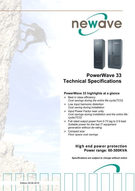
PowerWave 33 Technical Specifications
PowerWave 33 Technical Specifications
PowerWave 33 Technical Specifications
Create successful ePaper yourself
Turn your PDF publications into a flip-book with our unique Google optimized e-Paper software.
-<br />
Edition 29.06.2010<br />
<strong>PowerWave</strong> <strong>33</strong><br />
<strong>Technical</strong> <strong>Specifications</strong><br />
<strong>PowerWave</strong> <strong>33</strong> highlights at a glance<br />
Best in class efficiency<br />
Cost savings during the entire life-cycle(TCO)<br />
Low input harmonic distortion<br />
Cost saving during installation<br />
Input Power Factor near unity<br />
Cost savings during installation and the entire lifecycle(TCO)<br />
Full rated output power from 0.73 lag to 0.9 lead<br />
Suitable power for the last IT equipment<br />
generation without de-rating<br />
Compact size<br />
Floor space cost savings<br />
High end power protection<br />
Power range: 60-300KVA<br />
<strong>Specifications</strong> are subject to change without notice
TABLE OF CONTENTS<br />
Section-10<br />
10.1 POWERWAVE <strong>33</strong> SYSTEM DESCRIPTION .............................................................................................3<br />
10.2 TECHNICAL CHARACTERISTICS ............................................................................................................4<br />
10.2.1 MECHANICAL CHARACTERISTICS POWERWAVE <strong>33</strong> 60-100kVA...................................................4<br />
10.2.2 MECHANICAL CHARACTERISTICS POWERWAVE <strong>33</strong> 120-200kVA................................................5<br />
10.2.3 MECHANICAL CHARACTERISTICS POWERWAVE <strong>33</strong> 250-300kVA................................................5<br />
10.2.4 POWER SELECTION TABLE <strong>PowerWave</strong> <strong>33</strong>.......................................................................................6<br />
10.3 INPUT CHARACTERISTICS ......................................................................................................................6<br />
10.3.1 GRAPH: INPUT PF VERSUS % LOAD..................................................................................................7<br />
10.3.2 GRAPH: INPUT DISTORTION THDi VERSUS % LOAD.......................................................................7<br />
10.4 BATTERY CHARACTERISTICS................................................................................................................8<br />
10.5 OUTPUT CHARACTERISTICS ..................................................................................................................8<br />
10.5.1 GRAPH: AC – AC EFFICIENCY with Linear load @ cosφ 1..................................................................9<br />
10.5.2 GRAPH: Output Power in KW and KVA VERSUS cosφ Vout=230Vac rms line to neutral, 50Hz,<br />
minimum 40 battery blocks .....................................................................................................................9<br />
10.5.3 GRAPH: Output Power in KW and KVA VERSUS cosφ Vout=230Vac rms line to neutral, 50Hz, ≥<br />
44 battery blocks .................................................................................................................................................10<br />
10.6 ENVIRONMENTAL CHARACTERISTICS ...............................................................................................11<br />
10.7 STANDARDS............................................................................................................................................11<br />
10.8 COMMUNICATION ...................................................................................................................................12<br />
10.8.1 POWER MANAGEMENT DISPLAY (PMD)..........................................................................................12<br />
10.8.2 MIMIC DIAGRAM..................................................................................................................................12<br />
10.8.3 DISPLAY...............................................................................................................................................12<br />
10.8.4 CUSTOMER INTERFACES (Terminals X1, X2) .................................................................................13<br />
10.8.5 CUSTOMER INPUTS DRY PORTs: Terminal block X1.......................................................................13<br />
10.8.6 CUSTOMER OUTPUTS DRY PORTs : Terminal blocks X2...............................................................13<br />
10.9 OPTIONS ..................................................................................................................................................14<br />
10.9.1 MODEM/ETHERNET CARD / Newavewatch MANAGEMENT SOFTWARE...................................14<br />
10.9.2 SNMP card / WaveMon Management Software..................................................................................15<br />
10.9.3 BATTERY ENCLOSURES....................................................................................................................16<br />
10.10 BATTERY AUTONOMIES........................................................................................................................16<br />
10.10.1 EXAMPLES OF BATTERY AUTONOMY AT FULL LOAD WITH STANDARD BATTERY<br />
CABINETS AND STANDARD BATTERY CONFIGURATION............................................................................16<br />
10.11 INSTALLATION PLANNING ....................................................................................................................17<br />
10.11.1 HEAT DISSIPATION PER UPS RANGE WITH NON-LINEAR LOAD .............................................17<br />
10.12 WIRING AND BLOCK DIAGRAMS FOR ALL UPS FRAMES ................................................................18<br />
10.12.1 TERMINAL CONNECTIONS OVERVIEW .......................................................................................18<br />
10.12.2 INPUT FEED RATINGS ...................................................................................................................19<br />
www.newaveups.com<br />
00-9962_S10_NW_TDSPW<strong>33</strong>_60-300_GB_100629.DOC Page 2/19<br />
Printed in Switzerland – Modifications reserved
Section-10<br />
10.1 POWERWAVE <strong>33</strong> SYSTEM DESCRIPTION<br />
In environments that demand zero downtime, continuous power protection availability is essential. In order to<br />
respond to today’s dynamic IT and process-related environments that experience daily change through new server<br />
technologies, migration and centralization, resilient and easily adaptable power protection concepts are required.<br />
POWERWAVE <strong>33</strong> is the foundation for continuous power protection availability of network-critical infrastructures in<br />
enterprise data centers where business continuity has paramount importance and in process control environment<br />
where manufacturing continuity is essential.<br />
POWERWAVE <strong>33</strong> is an advanced double conversion UPS, VFI (Voltage and Frequency Independent) topology<br />
that responds fully to both highest availability and environmentally friendly requirements compliant with IEC 62040-<br />
3 (VFI-SS-111) standards.<br />
The POWERWAVE <strong>33</strong> UPS features innovations that combine to deliver the industry’s best key values like:<br />
enhanced power performance, parallel capability and connectivity’s interaction<br />
Newave’s Decentralized Parallel Architecture is based on stacking independent UPSs for power capacity increase<br />
or for redundancy purpose for power availability increase. When operating in parallel configuration, each<br />
POWERWAVE <strong>33</strong> can take the leadership role avoiding single points of failure in the parallel chain ensuring the<br />
highest level of power availability.<br />
The most demanding Data Centres starts with low power before achieving its full capacity. It is in this case<br />
essential to be able to recover the missing power requirement without risk for the applied load. POWERWAVE <strong>33</strong><br />
allows for system upgrades to meet the highest level of availability interruption free and without a temporary<br />
transfer the load to row mains (by-pass).<br />
This <strong>Technical</strong> Specification provides detailed technical information on the mechanical, electrical and<br />
environmental performance of the POWERWAVE <strong>33</strong> that can support to give answers to tender and end-user<br />
requirements. The POWERWAVE <strong>33</strong> was designed to respond to the most stringent safety, EMC and other<br />
important UPS standards.<br />
POWERWAVE <strong>33</strong> is a stand-alone UPS which can be paralleled for power protection increase and/or for<br />
redundancy purpose. It offers 6 different power ranges: 60-80-100-120-160-200-250-300kVA .<br />
Up to 10 UPS can be paralleled together to achieving the maximum power capacity of 3000kVA using common or<br />
separate battery configuration.<br />
Key Features of POWERWAVE <strong>33</strong>:<br />
• Best in class efficiency Energy-Operational cost savings (TCO)<br />
• Compact size,<br />
Small Footprint<br />
Space-saving of expensive floor space<br />
• Blade-server-friendly power<br />
Full power from 0.9 lead to 0.73 lag<br />
No de-rating with leading PF loads<br />
• Very low input current distortion THDi Gen-set power and installation cost saving<br />
THDi = < 3.5% @ 100% load<br />
• Input Power Factor near unity Cost savings during installation and the entire<br />
lifecycle (TCO)<br />
www.newaveups.com<br />
00-9962_S10_NW_TDSPW<strong>33</strong>_60-300_GB_100629.DOC Page 3/19<br />
Printed in Switzerland – Modifications reserved
10.2 TECHNICAL CHARACTERISTICS<br />
10.2.1 MECHANICAL CHARACTERISTICS POWERWAVE <strong>33</strong> 60-100kVA<br />
POWERWAVE <strong>33</strong><br />
without battery<br />
enclosure<br />
Power range kVA 60 80 100<br />
Dimensions (WxHxD) mm 550x1820x750 550x1820x750 550x1820x750<br />
Weight kg 230 240 245<br />
Colour Graphite grey (RAL 7024)<br />
POWERWAVE <strong>33</strong><br />
with Battery Enclosure A<br />
Max. Power connection kVA 60 80 100<br />
Dimensions (WxHxD) with<br />
80 battery blocks<br />
mm 970x1820x750 970x1820x750 970x1820x750<br />
Weight without battery kg 250 260 285<br />
Weight with battery<br />
with 80 block of 28Ah<br />
kg 1140<br />
1150<br />
1175<br />
Colour Graffito grey (RAL 7024)<br />
Section-10<br />
www.newaveups.com<br />
00-9962_S10_NW_TDSPW<strong>33</strong>_60-300_GB_100629.DOC Page 4/19<br />
Printed in Switzerland – Modifications reserved
POWERWAVE <strong>33</strong><br />
with Battery Enclosure B<br />
Max. Power connection kVA 60 80 100<br />
Dimensions (WxHxD) with<br />
120 battery blocks<br />
mm 1180x1820x750<br />
1180x1820x750<br />
1180x1820x750<br />
Weight without battery kg 260 270 295<br />
Weight with battery<br />
with 120 block of 28Ah<br />
1590<br />
1600<br />
1625<br />
Colour Graphite grey (RAL 7024)<br />
10.2.2 MECHANICAL CHARACTERISTICS POWERWAVE <strong>33</strong> 120-200kVA<br />
POWERWAVE <strong>33</strong><br />
Max. Power connection kVA 120 160 200<br />
Dimensions (WxHxD) mm 850x1820x750 850x1820x750 850x1820x750<br />
Weight kg 280 290 310<br />
Colour Graphite grey (RAL 7024)<br />
10.2.3 MECHANICAL CHARACTERISTICS POWERWAVE <strong>33</strong> 250-300kVA<br />
POWERWAVE <strong>33</strong><br />
Max. Power connection kVA 250 300<br />
Dimensions (WxHxD) mm 1100x1920x750 1100x1920x750<br />
Weight kg 390 410<br />
Colour Graphite grey (RAL 7024)<br />
Section-10<br />
www.newaveups.com<br />
00-9962_S10_NW_TDSPW<strong>33</strong>_60-300_GB_100629.DOC Page 5/19<br />
Printed in Switzerland – Modifications reserved
10.2.4 POWER SELECTION TABLE <strong>PowerWave</strong> <strong>33</strong><br />
kW / kVA<br />
350<br />
300<br />
250<br />
200<br />
150<br />
100<br />
50<br />
0<br />
POWERWAVE <strong>33</strong>: Power 60-300kVA (using 40 battery blocks)<br />
54.0 kW<br />
PW<strong>33</strong> @ PF 1.0<br />
108.0 kW<br />
90.0 kW<br />
72.0 kW<br />
10.3 INPUT CHARACTERISTICS<br />
UPS Model<br />
144.0 kW<br />
180.0 kW<br />
225.0 kW<br />
PW<strong>33</strong> 60<br />
PW<strong>33</strong> 80<br />
PW<strong>33</strong> 100<br />
PW<strong>33</strong> 120<br />
PW<strong>33</strong> 160<br />
PW<strong>33</strong> 200<br />
PW<strong>33</strong> 250<br />
PW<strong>33</strong> 300<br />
270.0 kW<br />
PW <strong>33</strong><br />
60<br />
Model<br />
160.0 kVA<br />
120.0 kVA<br />
100.0 kVA<br />
80.0 kVA<br />
60.0 kVA 72.0 kW<br />
54.0 kW<br />
PW <strong>33</strong><br />
80<br />
PW<strong>33</strong> @ PF 0.9<br />
PW <strong>33</strong><br />
100<br />
PW <strong>33</strong><br />
120<br />
90.0 kW<br />
200.0 kVA<br />
250.0 kVA<br />
144.0 kW<br />
108.0 kW<br />
300.0 kVA<br />
180.0 kW<br />
PW<strong>33</strong> 60<br />
PW<strong>33</strong> 80<br />
PW<strong>33</strong> 100<br />
PW<strong>33</strong> 120<br />
PW<strong>33</strong> 160<br />
PW<strong>33</strong> 200<br />
PW<strong>33</strong> 250<br />
PW<strong>33</strong> 300<br />
PW <strong>33</strong><br />
160<br />
PW <strong>33</strong><br />
200<br />
225.0 kW<br />
kVA<br />
KW<br />
PW <strong>33</strong><br />
250<br />
Section-10<br />
270.0 kW<br />
Output Rated Power kVA 60 80 100 120 160 200 250 300<br />
Nominal Input Voltage V 3x380/220V+N, 3x400V/230V+N, 3x415/240V+N<br />
Input Voltage Tolerance<br />
(ref to 3x400/230V) for Loads in %:<br />
V<br />
PW <strong>33</strong><br />
300<br />
(-23%/+15%) 3x308/177 V to 3x460/264 V for
10.3.1 GRAPH: INPUT PF VERSUS % LOAD<br />
Input Power Factor<br />
1<br />
0.8<br />
0.6<br />
0.4<br />
0.2<br />
0<br />
Input Power factor (Leading)<br />
0.96 0.985 0.99 0.99<br />
25 50 75 100<br />
Load %<br />
10.3.2 GRAPH: INPUT DISTORTION THDi VERSUS % LOAD<br />
Input THDi %<br />
11.5<br />
9.5<br />
7.5<br />
5.5<br />
3.5<br />
1.5<br />
Input Current Distortion THDi<br />
9.0<br />
6.0<br />
4.5<br />
25 50 75 100<br />
Load %<br />
3.5<br />
Section-10<br />
www.newaveups.com<br />
00-9962_S10_NW_TDSPW<strong>33</strong>_60-300_GB_100629.DOC Page 7/19<br />
Printed in Switzerland – Modifications reserved
10.4 BATTERY CHARACTERISTICS<br />
UPS Range<br />
60<br />
kVA<br />
Fixed Number of 12V Battery Blocks No. 40-50 40-50 50 40-50<br />
Maximum Battery Charger Current A 25A 50A 60A<br />
Battery Charging Curve Ripple free ; IU (DIN 41773)<br />
Temperature compensation ready Standard (temp. sensor optional)<br />
Battery Test Automatic and periodically (adjustable)<br />
Battery Type Maintenance free VRLA or NiCd<br />
10.5 OUTPUT CHARACTERISTICS<br />
UPS Range<br />
60<br />
kVA<br />
80<br />
kVA<br />
80<br />
kVA<br />
100<br />
kVA<br />
100<br />
kVA<br />
120<br />
kVA<br />
120<br />
kVA<br />
160<br />
kVA<br />
160<br />
kVA<br />
200<br />
kVA<br />
200(*)<br />
kVA<br />
250<br />
kVA<br />
250<br />
kVA<br />
Section-10<br />
Output Rated Power (@ min. 40 battery blocks) kVA 60 80 100 120 160 200 250 300<br />
Output Rated Power (@ min. 40 battery blocks) KW 54 72 90 108 144 180 225 270<br />
Output Current In PF 1.0 (400 V)<br />
(@ min. 40 battery blocks)<br />
A 78 104 130 157 209 261 326 391<br />
Output Rated Power (@ min. 44 battery blocks) kVA 60 80 100 120 160 200 250 300<br />
Output Rated Power (@ min. 44 battery blocks) KW 60 80 100 120 160 200 225 270<br />
Output Current In PF 1.0 (400 V)<br />
(@ min. 44 battery blocks)<br />
A 87 116 145 174 232 290 326 391<br />
Output Rated Voltage V 3x380/220V or 3x400/230V or 3x415/240V<br />
Output Voltage Stability %<br />
Static:<br />
Dynamic (Step load 0%-100% or 100%-0%)<br />
< +/- 1%<br />
< +/- 4%<br />
Output Voltage Distortion %<br />
With Linear Load<br />
With Non-linear Load (EN62040-3:2001)<br />
< 2%<br />
< 4%<br />
Output Frequency Hz 50 Hz or 60 Hz<br />
Synchronized with mains < +/- 2 %<br />
Output Frequency Tolerance % (selectable for bypass operation) or < +/- 4 %<br />
Bypass operation<br />
Permissible Unbalanced Load<br />
(All 3 phases regulated independently)<br />
Phase Angle Tolerance<br />
(With 100 % Unbalanced load)<br />
Free running +/- 0.1 %<br />
At Nominal Input voltage of 3x400 V +/- 15 %<br />
or 190 V to 264 V ph-N<br />
% 100%<br />
Deg. +/- 0 deg.<br />
Overload Capability on Inverter %<br />
125 % load<br />
150 % load<br />
Inverter: …..x In during 40 ms<br />
10 min.<br />
60 sec.<br />
Output short capability (RMS) A 3.2 2.4 2.6 2.2 2.3 2.5 2.0 2.2<br />
Crest - Factor<br />
Bypass: 10 x In during 10 ms<br />
3 : 1<br />
(*) Only with 50 battery blocks<br />
300<br />
kVA<br />
300<br />
kVA<br />
www.newaveups.com<br />
00-9962_S10_NW_TDSPW<strong>33</strong>_60-300_GB_100629.DOC Page 8/19<br />
Printed in Switzerland – Modifications reserved
10.5.1 GRAPH: AC – AC EFFICIENCY with Linear load @ cosφ 1<br />
%<br />
100<br />
95<br />
90<br />
85<br />
80<br />
75<br />
70<br />
Linear Load (cosφ=1)<br />
94.5 95 95.5 95.5<br />
94 94.5 94 93.5<br />
25 50 75 100<br />
Load %<br />
60-200<br />
250-300<br />
10.5.2 GRAPH: Output Power in KW and KVA VERSUS cosφ<br />
Vout=230Vac rms line to neutral, 50Hz, minimum 40 battery blocks<br />
CAP<br />
IND<br />
CAP<br />
IND<br />
PW<strong>33</strong><br />
60 80<br />
100<br />
PF kW kVA kW kVA kW kVA<br />
0.80 46 58 61 77 77 97<br />
0.85 50 59 66 78 83 98<br />
0.90 54 60 72 80 90 100<br />
0.95 54 56 72 75 90 94<br />
1.00 54 54 72 72 90 90<br />
0.95 54 56 72 75 90 94<br />
0.90 54 60 72 80 90 100<br />
0.85 51 60 68 80 85 100<br />
0.80 48 60 64 80 80 100<br />
0.75 45 60 60 80 75 100<br />
0.70 42 60 56 80 70 100<br />
0.65 39 60 52 80 65 100<br />
0.60 36 60 48 80 60 100<br />
Section-10<br />
PW<strong>33</strong><br />
120 160 200(*)<br />
250 300<br />
PF kW kVA kW kVA kW kVA kW kVA kW kVA<br />
0.80 92 116 122 154 193 241 231 291<br />
0.85 100 117 132 156 208 245 249 294<br />
0.90 108 120 144 160 225 250 270 300<br />
0.95 108 113 144 151 225 236 270 284<br />
1.00 108 108 144 144 225 225 270 270<br />
0.95 108 113 144 151 225 236 270 284<br />
0.90 108 120 144 160 225 250 270 300<br />
0.85 102 120 136 160 213 250 255 300<br />
0.80 96 120 128 160 200 250 240 300<br />
0.75 90 120 120 160 188 250 225 300<br />
0.70 84 120 112 160 175 250 210 300<br />
0.65 78 120 104 160 163 250 195 300<br />
0.60 72 120 96 160 150 250 180 300<br />
Changes of this tables without notice – modifications reserved<br />
(*) only using 50 battery blocks see page 10<br />
NOT ALLOWABLE<br />
www.newaveups.com<br />
00-9962_S10_NW_TDSPW<strong>33</strong>_60-300_GB_100629.DOC Page 9/19<br />
Printed in Switzerland – Modifications reserved
10.5.3 GRAPH: Output Power in KW and KVA VERSUS cosφ<br />
Vout=230Vac rms line to neutral, 50Hz, ≥ 44 battery blocks<br />
CAP<br />
IND<br />
CAP<br />
IND<br />
PW<strong>33</strong><br />
60 80 100<br />
PF kW kVA kW kVA kW kVA<br />
0.80 46 58 61 77 77 97<br />
0.85 50 59 66 78 83 98<br />
0.90 54 60 72 80 90 100<br />
0.95 57 60 76 80 95 100<br />
1.00 60 60 80 80 100 100<br />
0.95 57 60 76 80 95 100<br />
0.90 54 60 72 80 90 100<br />
0.85 51 60 68 80 85 100<br />
0.80 48 60 64 80 80 100<br />
0.75 45 60 60 80 75 100<br />
0.70 42 60 56 80 70 100<br />
0.65 39 60 52 80 65 100<br />
0.60 36 60 48 80 60 100<br />
Section-10<br />
PW<strong>33</strong><br />
120 160 200 (*)<br />
250 300<br />
PF kW kVA kW kVA kW kVA kW kVA kW kVA<br />
0.80 92 116 122 154 154 194 193 241 231 291<br />
0.85 100 117 132 156 166 195 208 245 249 294<br />
0.90 108 120 144 160 180 200 225 250 270 300<br />
0.95 114 120 152 160 190 200 225 236 270 284<br />
1.00 120 120 160 160 200 200 225 225 270 270<br />
0.95 114 120 152 160 190 200 225 236 270 284<br />
0.90 108 120 144 160 180 200 225 250 270 300<br />
0.85 102 120 136 160 170 200 213 250 255 300<br />
0.80 96 120 128 160 160 200 200 250 240 300<br />
0.75 90 120 120 160 150 200 188 250 225 300<br />
0.70 84 120 112 160 140 200 175 250 210 300<br />
0.65 78 120 104 160 130 200 163 250 195 300<br />
0.60 72 120 96 160 120 200 150 250 180 300<br />
Changes of this tables without notice – modifications reserved<br />
(*) only using 50 battery blocks<br />
www.newaveups.com<br />
00-9962_S10_NW_TDSPW<strong>33</strong>_60-300_GB_100629.DOC Page 10/19<br />
Printed in Switzerland – Modifications reserved
10.6 ENVIRONMENTAL CHARACTERISTICS<br />
Section-10<br />
UPS range 60kVA 80kVA 100 kVA<br />
120<br />
kVA<br />
160<br />
kVA<br />
200<br />
kVA<br />
250<br />
kVA<br />
300<br />
kVA<br />
Audible Noise with 100% /<br />
50% Load<br />
dBA < 65 < 69 < 71<br />
Operation temperature °C 0 – 40<br />
Ambient Temperature for<br />
Batteries (recommended)<br />
°C<br />
20 – 25<br />
Storage Temperature °C -25 - +70<br />
Battery Storage Time at<br />
Ambient Temperature<br />
Max. 6 months<br />
Max. altitude (above sea<br />
level)<br />
m 1000m (<strong>33</strong>00ft) without de-rating<br />
De-rating factor for use at<br />
altitudes above 1000m sea<br />
level according<br />
(IEC 62040-3)<br />
Meter above sea level (m / ft) De-Rating Factor for Power<br />
1500 / 4850 0.95<br />
2000 / 6600 0.91<br />
2500 / 8250 0.86<br />
3000 / 9900 0.82<br />
Relative Air-humidity Max. 95% (non-condensing)<br />
Accessibility<br />
Totally front accessibility for service and maintenance (no need for side, top or rear<br />
access)<br />
Positioning Min. 20 cm rear space (required for fan)<br />
Input and Output Power<br />
Cabling<br />
Efficiency AC-AC up to (at<br />
cosφ 1.0)<br />
(depending on UPS power)<br />
Eco-Mode efficiency at<br />
100% load<br />
10.7 STANDARDS<br />
%<br />
From the bottom on the front<br />
Load : 100 % 75 % 50% 25%<br />
95.5% 95.5% 95% 94.5%<br />
% 99 %<br />
Safety IEC/EN 62040-1-1:2003, IEC/EN 60950-1:2001/A11:2004<br />
Electromagnetic<br />
Compatibility<br />
IEC/EN 62040-2:2005, IEC/EN61000-3-2:2000,<br />
IEC/EN61000-6-2:2001,<br />
EMC Classes<br />
C3<br />
C2 domestic or industrial In < 16A<br />
C3 industrial In >16A C2 optional with filter<br />
Performance IEC/EN62040-3:2001<br />
Product certification CE<br />
Degree of protection IP 20<br />
www.newaveups.com<br />
00-9962_S10_NW_TDSPW<strong>33</strong>_60-300_GB_100629.DOC Page 11/19<br />
Printed in Switzerland – Modifications reserved
10.8 COMMUNICATION<br />
Power Management Display (PMD) LCD display<br />
RS232 on Sub-D9 port<br />
RS232 on USB port<br />
Customer Interfaces : Inputs<br />
DRY PORT<br />
Customer Interfaces : Outputs<br />
DRY PORT<br />
RS485 on RJ45 port<br />
RS485 on RJ45 port<br />
Slot for SNMP<br />
For monitoring and integration in network management<br />
1 Remote Shut down [EMERGENCY OFF (Normally closed)]<br />
1 GEN-ON (Normally open)<br />
1 Programmable Customer’s Inputs (Normally open)<br />
1 Temp. Sensor for Battery Control<br />
5 voltage free contacts<br />
For remote signalling and automatic computer shutdown<br />
Remote monitoring system with graphical display Option<br />
For multidrop purpose Option<br />
SNMP card<br />
For monitoring and integration in network management<br />
Option<br />
Slot for Newavewatch TM Newavewatch TM card for Premium Power Protection Option<br />
Section-10<br />
10.8.1 POWER MANAGEMENT DISPLAY (PMD)<br />
The user-friendly PMD consists of three parts the MIMIC DIAGRAM, CONTROL KEYS and LCD that provides the<br />
necessary monitoring information about the UPS.<br />
10.8.2 MIMIC DIAGRAM<br />
The mimic diagram serves to give the general status of the UPS. The LED-indicators show the power flow status<br />
and in the event of mains failure or load transfer from inverter to bypass and vice-versa the corresponding LEDindicators<br />
will change colour from green (normal) to red (warning). The LED’s LINE 1 (rectifier) and LINE 2<br />
(bypass) indicate the availability of the mains power supply. The LED’s INVERTER and BYPASS if green indicate<br />
which of the two are supplying power to the critical load. When the LED-indicator BATTERY is lit it means that the<br />
battery due to mains failure is supplying the load. The LED-indicator ALARM is a visual indication of any internal or<br />
external alarm condition. At the same time the audible alarm will be activated.<br />
10.8.3 DISPLAY<br />
The 2 x 20 character LCD simplifies the communication with the UPS. The menu driven LCD enables the access to<br />
the EVENT REGISTER, or to monitor the input and output U, I, f, P, Autonomy Time and other Measurement’s, to<br />
perform commands like start-up and shut-down of INVERTER or load transfer from INVERTER to BYPASS and<br />
vice-versa and finally it serves for the DIAGNOSIS (SERVICE MODE) for adjustments and testing (for more details<br />
see the USER MANUAL of <strong>PowerWave</strong> <strong>33</strong>).<br />
Power Management Display (PMD) of <strong>PowerWave</strong> <strong>33</strong><br />
www.newaveups.com<br />
00-9962_S10_NW_TDSPW<strong>33</strong>_60-300_GB_100629.DOC Page 12/19<br />
Printed in Switzerland – Modifications reserved
10.8.4 CUSTOMER INTERFACES (Terminals X1, X2)<br />
10.8.5 CUSTOMER INPUTS DRY PORTs: Terminal block X1<br />
Connection of Remote Shut down facilities, Generator Operation, Customers specials<br />
(see UM Section 9 / OPTIONS)<br />
Section-10<br />
10.8.6 CUSTOMER OUTPUTS DRY PORTs : Terminal blocks X2<br />
Provision of signals for the automatic and orderly shutdown of servers, AS400 or Automation building systems<br />
All voltage free contacts are rated 60 VAC max. and 500 mA max.:<br />
All the interfaces are connected to Phoenix Spring terminals with wires : 0.5 mm 2<br />
Block Terminal Contact Signal On Display Function<br />
X1<br />
X2<br />
X1 / 10 GND GND 12 Vdc source<br />
X1 / 9 IN +12Vdc (Max 200mA load)<br />
X1 / 8 GND GND Remote Shut down<br />
X1 / 7 IN +12Vdc (Do not remove the factory mounted bridge until an external remote shut down is connected)<br />
X1 / 6 GND GND Temperature Battery<br />
X1 / 5 IN +3.3Vdc (If connected, the battery charger current is batt. temperature dependent)<br />
X1 / 4 GND GND Customer IN 1<br />
X1 / 3 IN +12Vdc (Function on request, to be defined)<br />
X1 / 2 GND GND Customer IN 1 (default as Generator Operation)<br />
X1 / 1 IN +12Vdc (NC = Generator ON)<br />
X2 / 15 C COMMON_ALARM Common<br />
X2 / 14 NC ALARM NO Alarm Condition<br />
X2 / 13 NO Common Alarm (System)<br />
X2 / 12 C LOAD_ON_MAINS Common<br />
X2 / 11 NC Message (Load on Inverter)<br />
X2 / 10 NO Load on bypass (Mains)<br />
X2 / 9 C BATT_LOW Common<br />
X2 / 8 NC ALARM Battery OK<br />
X2 / 7 NO Battery Low<br />
X2 / 6 C LOAD_ON_INV Common<br />
X2 / 5 NC Message (Load on Mains bypass)<br />
X2 / 4 NO Load on Inverter<br />
X2 / 3 C MAINS_OK Common<br />
X2 / 2 NC ALARM Mains Failure<br />
X2 /1 NO Mains Present<br />
Phoenix Spring Terminals (X1, X2) Connection<br />
www.newaveups.com<br />
00-9962_S10_NW_TDSPW<strong>33</strong>_60-300_GB_100629.DOC Page 13/19<br />
Printed in Switzerland – Modifications reserved
10.9 OPTIONS<br />
- Modem/Ethernet card or Modem/GSM card for Newavewatch TM Management Software<br />
- SNMP card and WaveMon Management Software , Modbus Protocol, USB<br />
- External Battery Cabinets<br />
- Parallel kit, Synchron kit<br />
- In/output Transformer for special voltages<br />
- Back-feed protection<br />
- Temp. sensor for battery temp. control<br />
Section-10<br />
10.9.1 MODEM/ETHERNET CARD / Newavewatch MANAGEMENT SOFTWARE<br />
Newavewatch TM is a redundant remote monitoring and management service which is a part of the Premium Power<br />
Protection Concept, providing you with peace-of-mind protection, knowing the mission critical facility is under<br />
careful, continuous watch 24/7/365. There are two different solution cards Modem/Ethernet or Modem/GSM to<br />
connect the UPS to the outside world.<br />
Continuous monitoring is an affordable insurance policy to detect and warn before they become a crisis.<br />
Acquire key performance parameter and productivity information in real-time to empower you with the details<br />
needed to better understand machine performance and faster troubleshoot downtime events.<br />
Early warning system, so problems can be addressed before they become a real threat to the load.<br />
Professional experts, your virtual service technician onside.<br />
Total transparency of information and actions performed like Notification of all critical status changes,<br />
Coordination of equipment service, Reporting of all alarms with priorities.<br />
What are the features?<br />
• Redundant and secure communication<br />
• Alarm acknowledgment<br />
• Priority driven Management (with escalation)<br />
Comprehensive Management System<br />
– Reception and management of alarm calls from UPS<br />
– Storage of UPS Data in a database exportable in a CVS-format for easy handling in Excel<br />
– Unlimited number of UPS that can be managed<br />
– User administration with passwords and permission-level<br />
– Administration of Log file<br />
– Data logging with statistical analysis and diagnostics, report<br />
Visualization of the UPS data:<br />
• Current status (“single” and “parallel” operation)<br />
• Measured values for single or three phase<br />
• Recording function including graphs with zooming capabilities for selected measured values<br />
• Display of event log file<br />
• Display of UPS Parameters<br />
• Web Server functionality, for data access from any Web Browser<br />
www.newaveups.com<br />
00-9962_S10_NW_TDSPW<strong>33</strong>_60-300_GB_100629.DOC Page 14/19<br />
Printed in Switzerland – Modifications reserved
UPS systems<br />
1 ….1000<br />
Alarm<br />
Situation<br />
Problem in<br />
the System<br />
Interface Card<br />
Modem<br />
GSM<br />
Section-10<br />
10.9.2 SNMP card / WaveMon Management Software<br />
The Simple Network Management Protocol (SNMP) is a worldwide-standardized communication-protocol. It is used<br />
to monitor any device in the network via simple control language. The UPS-Management Software WaveMon also<br />
provides its data in this SNMP format with its internal software agent. The operating system you are using must<br />
support the SNMP protocol. We offer our WaveMon software with SNMP functionality for Novell, OS/2, all Windows<br />
running on INTEL and ALPHA, DEC VMS, Apple.<br />
Two types of SNMP interfaces with identical functionality are available: an external SNMP-Adapter (Box) and an<br />
internal SNMP-Card. Both can manage a parallel system (N modules) and return either global values - which are<br />
consistent for the whole parallel system - or specific values from the single modules.<br />
Ethernet<br />
MODEM<br />
Call<br />
Modem<br />
Network interface<br />
(ethernet)<br />
INTERNET<br />
MODEM<br />
External SNMP-Adapter<br />
Internal SNMP-Card<br />
9<br />
Communication<br />
UPS<br />
www.newaveups.com<br />
00-9962_S10_NW_TDSPW<strong>33</strong>_60-300_GB_100629.DOC Page 15/19<br />
Printed in Switzerland – Modifications reserved<br />
1<br />
…<br />
.1<br />
Communication<br />
INTERNET<br />
Management<br />
Station
10.9.3 BATTERY ENCLOSURES<br />
The integrated battery<br />
enclosures are part of the<br />
UPS, therefore cannot be<br />
defined as a separate battery<br />
cabinet<br />
BAT- ENC A & B<br />
Configuration<br />
accommodates:<br />
Strings :<br />
Terminals :<br />
Max.<br />
UPS &<br />
BAT- ENC A<br />
Only for 60, 80 and 100kVA<br />
80 Batt. Blocks for<br />
28Ah<br />
mounted on 16 shelves<br />
(5 blocks/shelf)<br />
2<br />
3 x M8<br />
UPS &<br />
BAT- ENC B<br />
Only for 60, 80 and 100kVA<br />
120 Batt. Blocks for<br />
28Ah<br />
mounted on 24 shelves<br />
(5 blocks/shelf)<br />
3<br />
3 x M8<br />
Fuse Type (Very Fast acting) A 2 x 3 x 100A 3 x 3 x 100A<br />
Dimensions of UPS and<br />
battery Side (WxHxD)<br />
Weight w/o trays and w/o<br />
batteries<br />
Battery configuration with<br />
BAT-ENC A & B<br />
mm 970x1820x750 1180x1820x750<br />
kg 20 30<br />
Batt. Config.<br />
(2x40)x28Ah<br />
Batt. Config.<br />
(3x40)x28Ah<br />
Section-10<br />
10.10 BATTERY AUTONOMIES<br />
10.10.1 EXAMPLES OF BATTERY AUTONOMY AT FULL LOAD WITH STANDARD BATTERY CABINETS<br />
AND STANDARD BATTERY CONFIGURATION<br />
28Ah battery<br />
UPS Range 60kVA 80kVA 100kVA 120kVA 160kVA 200kVA 250kVA 300kVA<br />
BAT-<br />
ENC<br />
Battery configuration Autonomy time @ PF=0.8<br />
Batt. Enclosure A (2x40)x28Ah<br />
Batt. Enclosure B (3x40)x28Ah<br />
13<br />
22<br />
9<br />
15<br />
7<br />
12<br />
www.newaveups.com<br />
00-9962_S10_NW_TDSPW<strong>33</strong>_60-300_GB_100629.DOC Page 16/19<br />
Printed in Switzerland – Modifications reserved
10.11 INSTALLATION PLANNING<br />
Clearances X Y<br />
Minimum 200 mm 900 mm<br />
UPS Frame type 60-100 kVA 60-80-100 kVA<br />
(with battery<br />
enclosure A & B)<br />
Dimensions (WxHxD) mm 550x1820x750 A: 970x1820x750<br />
B: 1180x1820x750<br />
Accessibility<br />
Section-10<br />
www.newaveups.com<br />
00-9962_S10_NW_TDSPW<strong>33</strong>_60-300_GB_100629.DOC Page 17/19<br />
Printed in Switzerland – Modifications reserved<br />
B<br />
a<br />
tt<br />
UPS<br />
Frames<br />
120-200 kVA 250-300 kVA<br />
850x1820x750 1100x1920x750<br />
Totally front accessibility for service and maintenance (no need for<br />
side, top or rear access)<br />
Positioning Min. 200 mm rear space (required for fan)<br />
Input and Output Power Cabling From the bottom on the front<br />
10.11.1 HEAT DISSIPATION PER UPS RANGE WITH NON-LINEAR LOAD<br />
UPS Range<br />
Heat Dissipation with 100% Non-linear<br />
Load per range (EN 62040-1-1:2003)<br />
Heat Dissipation with 100% Non-linear<br />
Load per range (EN 62040-1-1:2003)<br />
Airflow (25° - 30°C) with 100% Nonlinear<br />
Load per range (EN 62040-1-<br />
1:2003)<br />
X<br />
UPS<br />
Frames<br />
Open<br />
Doors<br />
Y<br />
Figure 1: UPS space recommendation Figure 2 : UPS + Battery space recommendation<br />
60<br />
kVA<br />
80<br />
kVA<br />
100<br />
kVA<br />
120<br />
kVA<br />
160<br />
kVA<br />
200<br />
kVA<br />
250<br />
kVA<br />
300<br />
kVA<br />
W 2970 3690 4950 5940 7920 9900 14400 17200<br />
BTU/h 10141 13521 16901 20281 27642 <strong>33</strong>802 491<strong>33</strong> 58686<br />
m 3 /h 1300 1500 1700 2500 2500 2500 <strong>33</strong>50 <strong>33</strong>40<br />
Heat Dissipation without load W 800 800 800 1000 1000 1000 1200 1200<br />
X<br />
Open<br />
Doors<br />
Y
Section-10<br />
10.12 WIRING AND BLOCK DIAGRAMS FOR ALL UPS FRAMES<br />
The customer has to supply the wiring to connect the UPS to the local power source. The installation inspection<br />
and initial start up of the UPS and extra battery cabinet must be carried out by a qualified service personnel such<br />
as a licensed service engineer from the manufacturer or from an agent authorised by the manufacturer.<br />
More details and procedure are mentioned in the user manual.<br />
10.12.1 TERMINAL CONNECTIONS OVERVIEW<br />
UPS Range<br />
Terminals (T)<br />
Connection Bar (B)<br />
Battery<br />
(+ / N / - )<br />
+PE<br />
Input Bypass<br />
3+N<br />
(N,2L1,2L2,2L3)<br />
Input Rectifier<br />
3+N+PE<br />
(N,1L1,1L2,1L3)<br />
Output load<br />
3+N+PE<br />
(N,3L1,3L2,3L3)<br />
Max. cable<br />
section<br />
admissible<br />
(mm²)<br />
Toghtening<br />
Torque<br />
(Nm)<br />
60kVA (Fig.1) 4 x M8 4 x 35 mm 2 4 x 35 mm 2 + PE M8 4 x 35 mm 2 + PE M8 35 3.5<br />
80kVA (Fig.1) 4 x M8 4 x 50 mm 2 4 x 50 mm 2 + PE M8 4 x 50 mm 2 + PE M8 50 5<br />
100kVA (Fig.1) 4 x M8 4 x 70 mm 2 4 x 70 mm 2 + PE M8 4 x 70 mm 2 + PE M8 95 8<br />
120kVA ((Fig.2) 4 x M10 4 x M10 5 x M10 5 x M10 185 Max. 50<br />
160kVA (Fig.2) 4 x M10 4 x M10 5 x M10 5 x M10 185 Max. 50<br />
200kVA (Fig.2) 4 x M10 4 x M10 5 x M10 5 x M10 240 Max. 50<br />
250kVA (Fig.3) 4 x M10 4 x M10 5 x M10 5 x M10 240 Max. 50<br />
300kVA (Fig.3) 4 x M10 4 x M10 5 x M10 5 x M10 240 Max. 50<br />
Fig. 1: 60-80-100 kVA<br />
N<br />
N 2L1 2L2<br />
1L1 1L2<br />
2L3<br />
1L3 N 3L1 3L3<br />
3L2<br />
Fig. 2: 120-160-200 kVA<br />
Dual input feed connections Single input feed connections<br />
N 1L1 2L1 1L2 2L2 1L3 2L3 N 3L1 3L2 3L3 + N <br />
PE<br />
Fig. 3: 250-300 kVA<br />
Dual input feed connections Single input feed connections<br />
N<br />
N 1L1 2L1<br />
1L2 2L2<br />
1L3 2L3 N 3L1 3L2 3L3 + N <br />
PE<br />
PE<br />
+<br />
N<br />
<br />
N 1L1<br />
2L1 1L2<br />
2L2 1L3<br />
2L3 N 3L1<br />
3L2 3L3<br />
+ N <br />
PE<br />
N 1L1<br />
1L2<br />
2L1<br />
2L2 2L3 N N<br />
1L3<br />
3L1 3L3<br />
3L2<br />
+ N <br />
www.newaveups.com<br />
00-9962_S10_NW_TDSPW<strong>33</strong>_60-300_GB_100629.DOC Page 18/19<br />
Printed in Switzerland – Modifications reserved<br />
PE<br />
PE
Section-10<br />
10.12.2 INPUT FEED RATINGS<br />
Cable Sections and Fuse Ratings recommended. Alternatively, local standards to be respected<br />
Block Diagram<br />
SINGLE INPUT FEED<br />
Cable E<br />
Fuse E<br />
Fuse A<br />
Cable A<br />
Frame<br />
F1<br />
Rectifier<br />
Inverter<br />
Static Switch<br />
IA2<br />
F2<br />
MAINS (3x380V/220V,<br />
3x400/230V,3x415/240V)<br />
Mainten. Bypass IA1<br />
Load<br />
Cable D<br />
Cable E<br />
Fuse E<br />
DUAL INPUT FEED<br />
Figure 3.3: Block Diagram <strong>PowerWave</strong> <strong>33</strong> from 60-300 KVA<br />
Fuse B Fuse C<br />
Cable B<br />
STANDARD VERSION (SINGLE INPUT FEED)<br />
Power<br />
(kVA)<br />
Fuse A<br />
(Agl/CB)<br />
Cable A<br />
(IEC 60950-1:2001)<br />
Cable D<br />
(IEC 60950-1:2001)<br />
Fuse E<br />
+/N/-<br />
Cable E<br />
+/N/-<br />
60<br />
80<br />
100<br />
120<br />
160<br />
200<br />
250<br />
300<br />
3x100<br />
3x125<br />
3x160<br />
3x200<br />
3x250<br />
3x315<br />
3x400<br />
3x500<br />
5x35<br />
5x50<br />
5x50<br />
5x70<br />
5x120 or 5x(2x50)<br />
5x185 or 5x(2x70)<br />
5x240 or 5x(2x95)<br />
5x(2x120)<br />
5x35<br />
5x50<br />
5x50<br />
5x70<br />
5x120 or 5x(2x50)<br />
5x185 or 5x(2x70)<br />
5x240 or 5x(2x95)<br />
5x(2x120)<br />
3x125A<br />
3x160A<br />
3x250A<br />
3x250A<br />
3x350A<br />
3x450A<br />
3x630A<br />
3x630A<br />
3x35+ PE<br />
3x50 + PE<br />
3x95 + PE<br />
3x120 + PE<br />
3x(2x70) + PE<br />
3x(2x95) + PE<br />
3x(2x150) + PE<br />
3x(2x150) + PE<br />
Cable C<br />
VERSION ON REQUEST (DUAL INPUT FEED)<br />
Power Fuse B Cable B<br />
Fuse C<br />
Cable C<br />
Cable D Fuse E Cable E<br />
(kVA)<br />
60<br />
80<br />
100<br />
120<br />
160<br />
200<br />
(Agl/CB)<br />
3x100<br />
3x125<br />
3x160<br />
3x200<br />
3x250<br />
3x315<br />
(IEC 60950-1:2001)<br />
5x35<br />
5x50<br />
5x50<br />
5x70<br />
5x120 or 5x(2x50)<br />
5x185 or 5x(2x70)<br />
(Agl/CB)<br />
3x100<br />
3x125<br />
3x160<br />
3x200<br />
3x250<br />
3x315<br />
(IEC 60950-1:2001)<br />
5x35<br />
5x50<br />
5x50<br />
5x70<br />
5x120 or 5x(2x50)<br />
5x185 or 5x(2x70)<br />
(IEC 60950-1:2001)<br />
5x35<br />
5x50<br />
5x50<br />
5x70<br />
5x120<br />
5x185<br />
+/N/-<br />
3x125A<br />
3x160A<br />
3x250A<br />
3x250A<br />
3x350A<br />
3x450A<br />
+/N/-<br />
3x35+ PE<br />
3x50+ PE<br />
3x95+ PE<br />
3x120+ PE<br />
3x(2x70) + PE<br />
3x(2x95) + PE<br />
250<br />
300<br />
3x400<br />
3x500<br />
5x240 or 5x(2x95)<br />
5x(2x120)<br />
3x400<br />
3x500<br />
5x240 or 5x(2x95)<br />
5x(2x120)<br />
5x240 or 5x(2x95)<br />
5x(2x120)<br />
3x630A<br />
3x630A<br />
3x(2x150) + PE<br />
3x(2x150) + PE<br />
Frame<br />
F1<br />
Rectifier<br />
Inverter<br />
Static Switch<br />
www.newaveups.com<br />
00-9962_S10_NW_TDSPW<strong>33</strong>_60-300_GB_100629.DOC Page 19/19<br />
Printed in Switzerland – Modifications reserved<br />
IA2<br />
F2<br />
Mainten. Bypass IA1<br />
Load<br />
Cable D<br />
MAINS (3x380V/220V,<br />
3x400/230V,3x415/240V)


