C-LAN Connectivity (Release 1.0) - Avaya Support
C-LAN Connectivity (Release 1.0) - Avaya Support
C-LAN Connectivity (Release 1.0) - Avaya Support

Create successful ePaper yourself
Turn your PDF publications into a flip-book with our unique Google optimized e-Paper software.
INTUITY AUDIX LX<br />
Message<br />
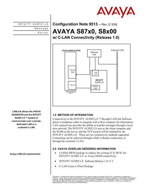
<strong>LAN</strong>Link allows the AVAYA<br />
S8300/8700 and the INTUITY<br />
AUDIX LX system to<br />
communicate over a private,<br />
dedicated <strong>LAN</strong> or a<br />
customer’s <strong>LAN</strong>.<br />
<strong>Avaya</strong> <strong>LAN</strong>Link requirements<br />
Server<br />
Configuration Note 9513 − Rev. E 3/08<br />
AVAYA S87x0, S8x00<br />
w/ C-<strong>LAN</strong> <strong>Connectivity</strong> (<strong>Release</strong> <strong>1.0</strong>)<br />
AVAYA S8300 & S8700<br />
Ethernet<br />
Port<br />
T/R Line<br />
Software <strong>Release</strong><br />
CM1.2<br />
<strong>1.0</strong> METHOD OF INTEGRATION<br />
<strong>Connectivity</strong> to the INTUITY AUDIX LX through <strong>LAN</strong>Link Software<br />
allows a telephone caller to integrate with a Host computer for information.<br />
<strong>LAN</strong> connectivity provides the ability to transfer messages through a local<br />
area network. The INTUITY AUDIX LX acts as the client computer and<br />
the S8300 as the server, and the TCP session will be initiated by the<br />
INTUITY AUDIX LX. There are two connectivity methods supported.<br />
Connecting can be achieved through a Hub or Router connection, or<br />
through the customer’s <strong>LAN</strong>.<br />
2.0 AVAYA OVER<strong>LAN</strong> ORDERING INFORMATION<br />
• <strong>LAN</strong>Set SWIN package to replace the existing X.25 DCIU for<br />
INTUITY AUDIX LX to <strong>Avaya</strong> S8300 connectivity.<br />
• INTUITY AUDIX LX Software <strong>Release</strong> <strong>1.0</strong>-17.5.<br />
• C-<strong>LAN</strong> Linux <strong>LAN</strong>set Package.<br />
Ethernet<br />
Hub<br />
<strong>LAN</strong><br />
Card<br />
INTUITY<br />
AUDIX LX<br />
Voice<br />
Card<br />
Customer <strong>LAN</strong><br />
Disclaimer: Configuration Notes are designed to be a general guide that reflects AVAYA Inc.’s experience configuring its<br />
systems. These notes cannot anticipate every configuration possibility given the inherent variations in all hardware and software<br />
products. Please understand that you could experience a problem not detailed in a Configuration Note. If so, please notify the<br />
TAC/TSO at (408) 922-1822, and if appropriate, we will include the problem in our next revision. AVAYA Inc. accepts no<br />
responsibility for errors or omissions contained herein.
PBX hardware requirements<br />
<strong>Avaya</strong> S8300/S8700 & C-<strong>LAN</strong><br />
3.0 PBX HARDWARE REQUIREMENTS<br />
• MM711 Analog voice port cards, 8 ports per card<br />
• Ethernet port on internal board<br />
3.1 PBX SOFTWARE REQUIREMENTS<br />
• Minimum Software on the S8300/87x0/8510:<br />
R011x.02.0.110.4; CM1.2<br />
Host switch must have <strong>Avaya</strong> Communication Manager 1.2 or higher<br />
Remote switches can be DCS or DCS+ to older switches, allowed with<br />
TCP/IP to <strong>Release</strong> 7.1.<br />
Note: For S83xx systems that do not have a C<strong>LAN</strong> card, administer the processor<br />
channel interface link as p to use the Processor Ethernet interface for adjunct<br />
connectivity. Without a C<strong>LAN</strong> card there is no need to administer Ethernet<br />
data mode.<br />
3.2 <strong>LAN</strong> CONNECTIVITY<br />
• Ethernet <strong>LAN</strong> connectivity - TCP/IP<br />
• Two Methods <strong>Support</strong>ed:<br />
• Direct through a dedicated 10baseT hub<br />
• Through a router on a customer <strong>LAN</strong><br />
3.3 CUSTOMER-PROVIDED EQUIPMENT<br />
• Wiring necessary to support the physical <strong>LAN</strong> (CAT 3 minimum)<br />
• Ethernet Hub (location of 10baseT - optional)<br />
3.4 DOCUMENTATION NEEDED<br />
See the INTUITY AUDIX LX documentation CD-ROM:<br />
• Getting Started<br />
• Switch Integration Planning<br />
• Administration for switch to INTUITY AUDIX LX<br />
• Installation for <strong>Avaya</strong> G700 Media Gateway controlled by an S8300<br />
or S8700 (PN 555-234-100)<br />
4.0 SUPPORTED FEATURES<br />
• Calling Party ID<br />
• Called Party ID<br />
• Internal vs. External<br />
The information contained in this document is provided by AVAYA Inc. to serve as a guide. See the disclaimer on page 1.<br />
2
<strong>Avaya</strong> S8300/S8700 & C-<strong>LAN</strong><br />
• Direct vs. Redirected Call<br />
• Busy/Ring-no-answer<br />
• Message Waiting<br />
5.0 OVER<strong>LAN</strong> QUALIFICATION<br />
See the INTUITY AUDIX LX documentation CD-ROM for Switch<br />
integration requirements and <strong>LAN</strong> integration.<br />
Planning Steps Before Installation<br />
Complete the planning worksheets in the <strong>LAN</strong>/Switch Integration<br />
Planning before the installation. Completing the Planning worksheets<br />
ensures that the installer has all the needed information.<br />
These worksheets include:<br />
- Voice ports stations on Host switch<br />
- Voice port extensions, equipment location and names<br />
- <strong>LAN</strong> Data for switch link to INTUITY AUDIX LX system<br />
- Names and IP addresses for INTUITY<br />
- Hunt groups for Host switch<br />
- Call coverage path<br />
- <strong>LAN</strong> Data for INTUITY AUDIX LX<br />
Determine how the connection being made from the <strong>Avaya</strong> INTUITY<br />
AUDIX LX system to the DEFINITY switch. Choose from the<br />
following:<br />
Option 1: Private <strong>LAN</strong>, no connectivity to customer <strong>LAN</strong> (uses<br />
private <strong>LAN</strong> addresses)<br />
• Preferred option, most robust and reliable, no dependency on<br />
customer’s network.<br />
• Crossover Cable is used for ease of connections.<br />
• Hub can be used instead of crossover cable extended<br />
distances. Up to four cables can be used.<br />
Option 2: Customer <strong>LAN</strong><br />
• Preferred option when using <strong>Avaya</strong> Message Manager or<br />
AUDIX Digital Networking.<br />
• Uses switch or router to provide a private collision domain.<br />
The information contained in this document is provided by AVAYA Inc. to serve as a guide. See the disclaimer on page 1.<br />
3
<strong>Avaya</strong> S8300/S8700 & C-<strong>LAN</strong><br />
• Minimal dependency on customer’s network.<br />
• Customer must provide equipment and administer network<br />
for private segment.<br />
• Customer’s <strong>LAN</strong> administer must be present during setup.<br />
If Option 2 is chosen, the following information is needed from the<br />
customer.<br />
a) Gather customer network physical connectivity information:<br />
1. Location of 10BaseT network access point (hub, switch or<br />
router)<br />
2. Distance between C-<strong>LAN</strong> and network access point (328 ft.<br />
or 100 m maximum)<br />
3. Wiring access point, existing or new, Category 5 minimum<br />
required<br />
a) Customer network administration information:<br />
1. IP address of C-<strong>LAN</strong>s, adjuncts, and gateways<br />
2. Node names of C-<strong>LAN</strong> adjuncts and gateways<br />
3. Subnet masks for all <strong>LAN</strong> segments containing C-<strong>LAN</strong>s or<br />
adjuncts<br />
4. Gateway IP address for all <strong>LAN</strong> segments that contain C-<br />
<strong>LAN</strong>s, adjuncts, or routers<br />
5. Will all endpoints (C-<strong>LAN</strong>s and adjuncts) be on the same<br />
local <strong>LAN</strong> segment.<br />
c) Network administration information needs to be mapped into specific<br />
administration fields.<br />
Sanity check of information obtained and verified by the customer:<br />
• If C-<strong>LAN</strong> and adjuncts are on the same <strong>LAN</strong> segment:<br />
• Gateway IP address and subnet mask information is valid.<br />
• All IP addresses contain the same subnet address.<br />
• If C-<strong>LAN</strong> and adjuncts are on a different <strong>LAN</strong> segments,<br />
gateway IP addresses are different.<br />
Without the above information, the <strong>Avaya</strong> technician will be unable to<br />
complete the installation. Installations that require the technicians to return<br />
because information was not available incur additional charges.<br />
Determine the location of the 10baseT network access point.<br />
The information contained in this document is provided by AVAYA Inc. to serve as a guide. See the disclaimer on page 1.<br />
4
Configure the Link that will connect<br />
to the INTUITY AUDIX LX system<br />
<strong>Avaya</strong> S8300/S8700 & C-<strong>LAN</strong><br />
Determine the distance between the C-<strong>LAN</strong> and the network access<br />
point.<br />
Determine if the customer will need <strong>LAN</strong> connectivity and support.<br />
NOTE: The <strong>LAN</strong> cable, the connector at the end of the cable for<br />
connection to the <strong>Avaya</strong> INTUITY AUDIX LX system, and <strong>LAN</strong><br />
administration not performed on the <strong>Avaya</strong> INTUITY AUDIX LX<br />
system are the responsibility of the customer, unless specified by<br />
contract.<br />
Working with the customer, determine the following:<br />
• The number of ports, drives, and mailboxes required for the<br />
INTUITY AUDIX LX. Obtain IP address of C-<strong>LAN</strong>s,<br />
adjuncts, and gateways.<br />
• The node names<br />
• Are all endpoints on the same local <strong>LAN</strong><br />
6.0 SWITCH CONFIGURATION FOR <strong>LAN</strong> INTEGRATION<br />
For more information, click Help on the appropriate page or see the INTUITY<br />
AUDIX LX CD ROM for detailed information.<br />
The following steps are required on the AVAYA S8300 Switch to prepare for the<br />
C-<strong>LAN</strong> Integration. This is done on the “Host” switch:<br />
• Change dial-plan parameters, enter a number between 1-99 in the<br />
local node number.<br />
• Assign the DIAL P<strong>LAN</strong> TABLE as required:<br />
• DIAL P<strong>LAN</strong> PARAMETERS<br />
• Local Node Number: X (1-99)<br />
• ETA Node Number:<br />
• ETA Routing Pattern:<br />
• UDP Extension Search Order: local-extensions-first<br />
• 6-Digit Extension Display Format: xx.xx.xx<br />
• 7-Digit Extension Display Format: xxx-xxxx<br />
• Define the <strong>Avaya</strong> INTUITY AUDIX LX system voice ports as unique<br />
stations. Define the following:<br />
STATION<br />
Extension: XXX or XXXX (Enter the 3 or 4 digit extension number)<br />
Type: 2500 (Designate the ports as 2500)<br />
The information contained in this document is provided by AVAYA Inc. to serve as a guide. See the disclaimer on page 1.<br />
5
<strong>Avaya</strong> S8300/S8700 & C-<strong>LAN</strong><br />
Name: Audix 1<br />
COS: X (Enter the COS defined for this group of ports)<br />
FEATURE OPTIONS:<br />
LWC Reception: audix<br />
LWC Activation? n<br />
Data Restriction? y<br />
Switchhook Flash? y<br />
Adjunct Supervision? Y<br />
Multimedia Mode: basic<br />
AUDIX Name: Intuity<br />
Define the analog voice port stations on the Host switch using the “add<br />
station voice port extension”, use “duplicate station for the remaining<br />
voice ports.<br />
Define a unique Class of Restriction (COR), and Class of Service (COS), per<br />
customer policy.<br />
CLASS OF RESTRICTION<br />
COR Number: xx<br />
COR Description: Audix Ports FRL: x<br />
APLT? y<br />
Can Be Service Observed? n Calling Party Restriction: none<br />
Can Be A Service Observer? n Called Party Restriction: none<br />
Time of Day Chart: 1 Forced Entry of Account Codes? n<br />
Priority Queuing? n Direct Agent Calling? n<br />
Restriction Override: all Facility Access Trunk Test? n<br />
Restricted Call List? n Can Change Coverage? n<br />
Access to MCT? y Fully Restricted Service? n<br />
Group II Category For MFC: X<br />
Send ANI for MFE? n<br />
MF ANI Prefix: Automatic Charge Display? n<br />
Hear System Music on Hold? y PASTE (Display PBX Data on Phone)? n<br />
Can Be Picked Up By Directed Call Pickup? n<br />
The information contained in this document is provided by AVAYA Inc. to serve as a guide. See the disclaimer on page 1.<br />
6
<strong>Avaya</strong> S8300/S8700 & C-<strong>LAN</strong><br />
Can Use Directed Call Pickup? n<br />
Group Controlled Restriction: inactive<br />
MF Incoming Call Trace? n<br />
Brazil Collect Call Blocking? n<br />
Block Transfer Display? n<br />
Block Enhanced Conference/Transfer Displays? y<br />
Remote Logout of Agent? n<br />
Station Lock COR: 11<br />
CALLING PERMISSION (Enter "y" to grant permission to call specified<br />
COR)<br />
0? y 12? y 24? y 36? y 48? y 60? y 72? y 84? y<br />
1? y 13? y 25? y 37? y 49? y 61? y 73? y 85? y<br />
2? y 14? y 26? y 38? y 50? y 62? y 74? y 86? y<br />
3? y 15? y 27? y 39? y 51? y 63? y 75? y 87? y<br />
4? y 16? y 28? y 40? y 52? y 64? y 76? y 88? y<br />
5? y 17? y 29? y 41? y 53? y 65? y 77? y 89? y<br />
6? y 18? y 30? y 42? y 54? y 66? y 78? y 90? y<br />
7? y 19? y 31? y 43? y 55? y 67? y 79? y 91? y<br />
8? y 20? y 32? y 44? y 56? y 68? y 80? y 92? y<br />
9? y 21? y 33? y 45? y 57? y 69? y 81? y 93? y<br />
10? y 22? y 34? y 46? y 58? y 70? y 82? y 94? y<br />
11? y 23? y 35? y 47? y 59? y 71? y 83? y 95? Y<br />
Assign the CLASS OF SERVICE for the voice ports.<br />
Auto Callback: n<br />
Call Fwd-All Calls y<br />
Data Privacy n<br />
Priority Calling n<br />
Console Permissions n<br />
Off-hook Alert n<br />
Client Room n<br />
The information contained in this document is provided by AVAYA Inc. to serve as a guide. See the disclaimer on page 1.<br />
7
<strong>Avaya</strong> S8300/S8700 & C-<strong>LAN</strong><br />
Restrict Call Fwd-Off Net y<br />
Call Forwarding Busy/DA n<br />
Personal Station Access (PSA) n<br />
Extended Forwarding All n<br />
Extended Forwarding B/DA n<br />
Trk-to-Trk Transfer Override n<br />
QSIG Call Offer Originations n<br />
• Define voice port extensions, equipment location and names<br />
• Define a hunt group and add the <strong>Avaya</strong> INTUITY AUDIX LX system<br />
voice ports to that hunt group (configure local and remote hunt groups as<br />
required). Define the local hunt group as ‘ucd-mia’, and define the<br />
message center as ‘AUDIX’. Define the remote hunt group as ‘ucd’ or<br />
‘ucd-mia’ and define the message center as ‘rem-AUDIX’.<br />
The following example defines group 99, and 299 as the pilot number and<br />
ext 391, 392, 393 and 394 as the extensions in the hunt group.<br />
HUNT GROUP<br />
Group Number: 99 ACD? n<br />
Group Name: Audix Queue? n<br />
Group Extension: xxx Vector? n<br />
Group Type: ucd-mia Coverage Path:<br />
TN: 1 Night Service Destination:<br />
COR: 1 MM Early Answer? n<br />
Message Center: audix<br />
Message Center AUDIX Name: Intuity<br />
Primary? n<br />
Calling Party Number to INTUITY AUDIX? y<br />
LWC Reception: audix<br />
AUDIX Name: Intuity<br />
Messaging Server Name:<br />
Group Number: 99 Group Extension: xxx Group Type: ucd-mia<br />
Member Range Allowed: 1 - 1500 Administered Members (min/max): 1/4<br />
Total Administered Members: 4<br />
The information contained in this document is provided by AVAYA Inc. to serve as a guide. See the disclaimer on page 1.<br />
8
<strong>Avaya</strong> S8300/S8700 & C-<strong>LAN</strong><br />
GROUP MEMBER ASSIGNMENTS<br />
Ext Name (24 characters) Ext Name (24 characters)<br />
1: xxx Audix 1<br />
2: xxx Audix 2<br />
3: xxx Audix 3<br />
4: xxx Audix 4<br />
• On the System-Parameters Maintenance screen, page 2, change system<br />
parameters maintenance and set Packet Intf2 to ‘Y’ to activate the Packet-<br />
Interface 2. Note that “01A07” is used as an example only. This example<br />
shows the bottom of the screen only, do not change any other existing entries<br />
on this page.<br />
SPE OPTIONAL BOARDS<br />
Packet Intf1? n Packet Intf2? y<br />
Bus Bridge: 01A07<br />
• If the S8300 or INTUITY AUDIX LX is connected to a customer<br />
<strong>LAN</strong>/WAN the customer must supply the IP addresses and subnet<br />
mask to be used. In addition, they must also supply the IP addreses for<br />
remote locations.<br />
• Configure Node Names AUDIX MSA (change node-names audixmsa)<br />
Define the AUDIX node name and IP address as appropriate. The<br />
following is an example of the IP addresses defined when listing node<br />
names.<br />
NODE NAMES<br />
Type Name IP Address<br />
AUDIX Intuity xxx.xxx.x.xx<br />
IP cdr xxx.xxx.xxx.xxx<br />
IP cms xxx.xxx.xxx.xx<br />
IP default 0 .0 .0 .0<br />
IP gateway xx.xxx.xx.xxx<br />
IP procr xxx.xxx.x.xxx<br />
• Configure the IP Interface screen (change ip-interfaces).<br />
Inter-region IP connectivity allowed to: N<br />
Enabled: Y<br />
The information contained in this document is provided by AVAYA Inc. to serve as a guide. See the disclaimer on page 1.<br />
9
<strong>Avaya</strong> S8300/S8700 & C-<strong>LAN</strong><br />
Type : c-lan<br />
Slot: (Enter the equipment location)<br />
Code/Sfx:<br />
Node Name:<br />
Subnet Mask: Default entry as 255.255.255.0<br />
Gateway Address:<br />
Network Region: 1<br />
NODE NAMES<br />
Audix Names IP Address MSA Names IP Address<br />
1. intuity 19<br />
2<br />
.16<br />
8<br />
. 2 . 3 1. . . .<br />
• The Ethernet data module does not apply to the S8300.<br />
• Administer a processor channel for the link from the switch to the<br />
<strong>Avaya</strong> INTUITY AUDIX LX AUDIX LX system.<br />
From the Processor Channel Screen (Use the change communicationinterface<br />
processor-channels command to access this.)<br />
PROCESSOR CHANNEL ASSIGNMENT<br />
The information contained in this document is provided by AVAYA Inc. to serve as a guide. See the disclaimer on page 1.<br />
10<br />
Page 1 of 6<br />
Proc Gtwy Interface Destination Session Mach<br />
Chan Enable Appl. To Mode Link / Chan Node Port Local / Remote ID<br />
1: y audix s P 5002 intuity 0 1 1 1<br />
• Use any Processor Channel. Processor channel “1” is preferred. Processor<br />
Channel “59”, or any other channel may be used to match previous version<br />
of a ECS installation.<br />
• Enable: Always set to “y”, this channel will not go active until the link is<br />
enabled on the Ethernet Data Module.<br />
• Appl: Set to “audix” for INTUITY AUDIX LX.<br />
• Mode: Always set to “s” for INTUITY AUDIX LX application.
<strong>Avaya</strong> S8300/S8700 & C-<strong>LAN</strong><br />
• Interface Link must be set to “P” (primary) for an S8300. For S8700 set it<br />
to “1” (or the appropriate link; Note: range is 1 to 33).<br />
• Channel: Set to “5002” for INTUITY AUDIX LX. If this is the only<br />
switch connected to the INTUITY AUDIX LX, if this is a shared INTUITY<br />
AUDIX LX contact ATAC or NIC support. Multiple nodes will not be<br />
supported without a design. You must contact the Network Implementation<br />
Center.?? Took out sentence that says submit E-1154 to the SDSC.??<br />
• Destination Node: This name must match the name assigned to INTUITY<br />
AUDIX LX on the Node-Name screen.<br />
• Destination Port: always “0” for direct connect INTUITY AUDIX LX.<br />
•Session-Local: This field must match the Node Number assigned on the<br />
Dial Plan Screen for INTUITY AUDIX LX and CMS, the session local is<br />
always “1”.<br />
• Session-Remote: This field must match the AUDIX Number assigned in<br />
the INTUITY AUDIX LX and the Mach ID field on this Processor Channel<br />
screen. For INTUITY AUDIX LX this field is always “1”.<br />
• Mach ID: This field must match the AUDIX Number assigned in the<br />
INTUITY AUDIX LX and the Session-Remote field on this Processor<br />
Channel screen.<br />
• If this customer is using Router’s then you must configure the IP router<br />
table. From the IP Routing Screen (add ip-route xxx), this step only applies<br />
when bypassing the switch’s default IP gateway. It is rare for this type of<br />
configuration.<br />
You must define the following:<br />
- Route Number:<br />
- Destination Node:<br />
- Gateway:<br />
- C-<strong>LAN</strong> Board<br />
- Metric:<br />
The information contained in this document is provided by AVAYA Inc. to serve as a guide. See the disclaimer on page 1.<br />
11
<strong>Avaya</strong> S8300/S8700 & C-<strong>LAN</strong><br />
IP ROUTE 1<br />
Route Number: 1<br />
Destination Node: gateway<br />
Gateway: ethernet<br />
C-<strong>LAN</strong> Board: XXXXX<br />
Metric: 0<br />
IP ROUTE 2<br />
Route Number: 2<br />
Destination Node: cms<br />
Gateway: gateway<br />
C-<strong>LAN</strong> Board: XXXXX<br />
Metric: 0<br />
• Set up a coverage path for access to the voice port hunt group for<br />
message retrieval.<br />
COVERAGE PATH<br />
Coverage Path Number: X<br />
Hunt after Coverage? n<br />
Next Path Number: Linkage<br />
COVERAGE CRITERIA<br />
Station/Group Status Inside Call Outside Call<br />
Active? n n<br />
Busy? y y<br />
IP ROUTING<br />
IP ROUTING<br />
The information contained in this document is provided by AVAYA Inc. to serve as a guide. See the disclaimer on page 1.<br />
12<br />
Page 1 of 1<br />
Page 1 of 1
<strong>Avaya</strong> S8300/S8700 & C-<strong>LAN</strong><br />
Don't Answer? y y Number of Rings: 3<br />
All? n n<br />
DND/SAC/Goto Cover? y y<br />
COVERAGE POINTS<br />
Terminate to Coverage Pts. with Bridged Appearances? N<br />
Point1: h99 Rng: Point2: Point3:<br />
Point4: Point5: Point6:<br />
• Apply the coverage path to stations, and if the switch is an r model,<br />
specify the node name of the <strong>Avaya</strong> INTUITY AUDIX LX system for<br />
each station that has a voice mailbox on the <strong>Avaya</strong> INTUITY AUDIX LX<br />
system.<br />
The first step in administering the INTUITY AUDIX LX system for C-<strong>LAN</strong><br />
integration is to place the INTUITY AUDIX LX onto the customers <strong>LAN</strong>.<br />
- continued on next page -<br />
The information contained in this document is provided by AVAYA Inc. to serve as a guide. See the disclaimer on page 1.<br />
13
<strong>Avaya</strong> S8300/S8700 & C-<strong>LAN</strong><br />
6.1 INTUITY CONFIGURATION FOR <strong>LAN</strong> INTEGRATION<br />
For more information on configuring the INTUITY AUDIX LX TM , click<br />
Help on the appropriate page, or refer to the INTUITY AUDIX LX TM CD<br />
ROM and refer to the Switch Integration chapters for detailed information.<br />
The following are the steps required for an INTUITY AUDIX LX TM.<br />
R2.x. INTUITY AUDIX LX 2.x uses a simpler GUI as shown in our<br />
example screen below. All you need do is open the category you will<br />
administer (shown in yellow text next to the small white triangles in the<br />
left column). You can expand these by click on the white triangle to left of<br />
it. Once this is done the category will expand providing choices below it.<br />
In our example we have opened Switch Administration. The triangle points<br />
down to indicate it is open.<br />
Here we selected Interface Parameters. This is noted by the white rectangle<br />
around the text Interface Parameters in blue.<br />
Important: This is an example screen of IALX R2.x Administration. The values<br />
shown here may be different than those you will need to enter.<br />
Please read the CN for more detailed information.<br />
HINT: When changes to the Switch Interface Administration are<br />
completed, the voice system must then be stopped and started.<br />
• Start at the Administration main menu<br />
• Select Basic System Administration.<br />
• Select Switch Selection.<br />
Once a selection is made the appropriate screen will open allowing you<br />
to enter the parameters as noted in the CN.<br />
The information contained in this document is provided by AVAYA Inc. to serve as a guide. See the disclaimer on page 1.<br />
14
<strong>Avaya</strong> S8300/S8700 & C-<strong>LAN</strong><br />
NOTE: The Definity OVER<strong>LAN</strong> software may have to be loaded from<br />
the software CD that came with the Intuity LX.<br />
• Under Switch Administration:<br />
- Click on Switch Selection<br />
- Select UNITED STATES – DEFINITY OVER<strong>LAN</strong><br />
- Click Save<br />
NOTE: You must stop and start the voice system to make these changes active.<br />
• Under Voice System Admin administer the following as required<br />
- Click on Assign Chans to Groups<br />
- If you are setting up different channels to different groups,<br />
complete these fields as follows:<br />
o Channels: Enter a number or range (for example, 0,1,2 or 0 1 2 or 2-<br />
4 or all).<br />
o Groups: Enter a number or range (for example, 0,1,2 or 0 1 2 or 2-4<br />
or all).<br />
- Click Save<br />
- Click Assign PBX Ext/Chans<br />
o Starting PBX Extension: Enter a phone number (the pilot number)<br />
for the first channel (up to 7 digits).<br />
o Starting Channel Number: Enter a number (start at channel 0).<br />
o Ending Channel Number: Enter the last channel number.<br />
IMPORTANT: If numbers are not sequential then you have to do this<br />
for each extension and channel.<br />
- Click Save<br />
- Click Assign Services/Chans<br />
o Channel: Enter the channel number and/or a range of numbers.<br />
o Service: (You have the option to select *DNIS_SVC, AUDIX,<br />
Chan Tran, chandip, or init_xfer). Choose *DNIS_SVC.<br />
- Click Save<br />
- Display Number Services (Numbers you assign to each installed service)<br />
- Click Save<br />
• Under Call Transfer Administration. Customers have the option to<br />
select numbers to be allowed or denied when they are performing<br />
transfers. You can add, delete and display numbers here. Restrictions<br />
(denied numbers) can also be administered if any are to be used.<br />
- If you click on Allowed Number Display, you will see the<br />
following for a four-digit dial plan:<br />
From To<br />
0 9999<br />
• Under Switch Administration<br />
The information contained in this document is provided by AVAYA Inc. to serve as a guide. See the disclaimer on page 1.<br />
15
<strong>Avaya</strong> S8300/S8700 & C-<strong>LAN</strong><br />
- Click Switch Link Administration<br />
o Switch Link Type: <strong>LAN</strong> (grayed out, cannot be altered)<br />
o Extension Length : X (X = number of digits in extension)<br />
o Host Switch Number : 1<br />
o Audix Number : 1<br />
o Country: United States (grayed out, cannot be altered)<br />
o Switch : Definity Overlan (grayed out, cannot be altered)<br />
o Switch Number: 1<br />
o IP Address/Host Name: xxx.xxx.xxx<br />
o TCP/IP Port: 5002<br />
NOTE: 5002 is the TCP port for the INTUITY AUDIX LX System used<br />
on a DEFINITY. 5002 must always be assigned to the host<br />
switch.<br />
- Click Save<br />
• Under Server Administration<br />
- Click TCP/IP Network Configuration<br />
- Administer the following:<br />
o Host Name: AUDIX (This is the message server name)<br />
o Default Gateway Address: See Note below<br />
o Primary Name + Domain: Audix.<strong>Avaya</strong>.com<br />
o IP Address: xx.xx.xxx.xx (Intuity Audix IP address)<br />
o Subnet Mask: 255.255.255.0<br />
o Aliases: (enter the alias of the interface you are configuring such as<br />
Corporate <strong>LAN</strong>, Private <strong>LAN</strong>, etc.)<br />
o Network Media Type: auto detect (default)<br />
o Enable DNS: No (Enter Yes only if the customer is using a<br />
name server.)<br />
o Domain Name: (Name used as default domain for machines)<br />
o Name Server: xxx.xx.xxx.xxx (IP addresses of the DNS servers)<br />
o Search Order: (Specifies the domains that are to be searched when<br />
the fully qualified name is not provided for a<br />
machine on the customer network)<br />
- Click Save<br />
NOTE: Do not define a default gateway until the physical connection is made.<br />
For remote switches that are not on the IP Network, the host switch<br />
provides translation and forwarding facilities on a separate TCP port.<br />
This port number and host switch IP address or host name is specified<br />
along with the remote switch number.<br />
See the CD-ROM for further details on testing the installation<br />
The information contained in this document is provided by AVAYA Inc. to serve as a guide. See the disclaimer on page 1.<br />
16
<strong>Avaya</strong> S8300/S8700 & C-<strong>LAN</strong><br />
-----------STOPPED HERE_________<br />
To view the status of the Link:<br />
• Under Diagnostics<br />
• Select Link Diagnostics<br />
• Click on Check Link<br />
• Switch Number of the Link: 1 (or whichever link # you want to check)<br />
• Click on Check Switch<br />
• You should see “The Switch Link is already UP” at the top of the<br />
screen directly under “Link Diagnostics.”<br />
To verify packet information is being passed from the Server you can check<br />
the link using a ping test in the INTUITY AUDIX LX.<br />
• Under Diagnostics<br />
• Select Ping Another Server<br />
• IP Address/Host Name: xxx.xxx.xxx.xxx (enter Server IP Address)<br />
• Click Ping Test<br />
• The Packet Statistics will be displayed<br />
NOTE: If you encounter problems while performing these tasks, review<br />
the “switch log” before escalating problems to your Technical<br />
<strong>Support</strong> Center.<br />
At this point all the required programming is complete. Please stop<br />
and restart the INTUITY AUDIX LX.<br />
- continued on next page –<br />
The information contained in this document is provided by AVAYA Inc. to serve as a guide. See the disclaimer on page 1.<br />
17
<strong>Avaya</strong> S8300/S8700 & C-<strong>LAN</strong><br />
6.2 CONNECTIVITY FOR C-<strong>LAN</strong> CONNECTION<br />
Option 1: Ethernet connection from the S8300 and the INTUITY<br />
AUDIX LX system to the customers network equipment (switch, hub,<br />
router)<br />
AVAYA S8300<br />
PC<br />
7088<br />
C-<strong>LAN</strong><br />
ETHERNET PORT<br />
IP ADDRESS<br />
192.168.1.1<br />
Option 2: Cross over cable from the S8300 switch directly into the<br />
INTUITY AUDIX LX system.<br />
AVAYA S8300<br />
C-<strong>LAN</strong><br />
ETHERNET PORT<br />
IP ADDRESS<br />
192.168.1.1<br />
CONNECTIVITY WITH ROUTERS<br />
AVAYA S8300<br />
C-<strong>LAN</strong><br />
ETHERNET PORT<br />
IP ADDRESS<br />
192.168.2.2<br />
RTR<br />
1<br />
Gateway1<br />
IP ADDRESS<br />
192.168.2.1<br />
Switch<br />
Hub<br />
Router<br />
Cross over<br />
Cat 5 cable<br />
RTR<br />
2<br />
Gateway2<br />
IP ADDRESS<br />
192.168.100.1<br />
INTUITY<br />
AUDIX LX<br />
NETWORK<br />
CARD<br />
10H/100H<br />
IP ADDRESS<br />
192.168.1.2<br />
INTUITY<br />
AUDIX LX<br />
NETWORK<br />
CARD<br />
10H/100H<br />
IP ADDRESS<br />
192.168.1.2<br />
The information contained in this document is provided by AVAYA Inc. to serve as a guide. See the disclaimer on page 1.<br />
18<br />
INTUITY<br />
AUDIX LX<br />
NETWORK CARD<br />
IP ADDRESS<br />
192.168100.3
<strong>Avaya</strong> S8300/S8700 & C-<strong>LAN</strong><br />
The following illustration shows a typical configuration of a connection to<br />
remote switches.<br />
INTUITY<br />
AUDIX LX<br />
192.168.2.5<br />
(IP Address)<br />
Voice Lines<br />
Ethernet <strong>LAN</strong><br />
DEFINITY<br />
Switch<br />
Remote - Node #3<br />
ISDN<br />
<strong>Avaya</strong> S8300<br />
<strong>Release</strong><br />
Switch<br />
(Host Node #1)<br />
192.168.2.2<br />
192.168.2.71<br />
The information contained in this document is provided by AVAYA Inc. to serve as a guide. See the disclaimer on page 1.<br />
PPP<br />
192.168.2.7<br />
5<br />
DEFINITY<br />
<strong>Release</strong> 7<br />
(Remote - Node # 4)<br />
192.168.2.1<br />
0<br />
DEFINITY<br />
<strong>Release</strong> 7<br />
Switch<br />
(Remote - Node #2)<br />
19
Installing the voice lines<br />
Important notes<br />
<strong>Avaya</strong> S8300/S8700 & C-<strong>LAN</strong><br />
7.0 INSTALLING THE VOICE LINES<br />
• Each voice card supports four analog (Tip/Ring) connections. The<br />
voice path between the MM711 analog card and the INTUITY<br />
AUDIX LX TM requires one pair in each RJ11 connection of the<br />
voice card.<br />
• To ensure that the ports are physically connected correctly, ask the<br />
switch administrator to place calls to each individual INTUITY<br />
AUDIX LX TM voice channel, one at a time. Use the Voice<br />
Channel Monitor under System Configuration from the Main Menu<br />
to monitor that the correct channel is dialed from the switch. Cards<br />
are assigned bottom to top and ports are assigned right to left.<br />
8.0 CONSIDERATIONS<br />
8.1 C-<strong>LAN</strong> will not support synchronous PPP and asynchronous<br />
PPP. 10baseT Half-Duplex will be supported.<br />
8.2 DCS is <strong>Avaya</strong>’s networking package. In a DCS environment,<br />
subscribers on the remote nodes might not have the same<br />
integration feature functionality as those on the hub node.<br />
8.3 AUDIX Networking is supported through modems.<br />
8.4 Digital Networking is supported.<br />
8.5 A patch is required with Multi Vantage software 1.2. This patch<br />
allows callers who dial invalid numbers to be returned to the main<br />
menu and given the option to dial another number. Without this<br />
patch the system will drop callers who dial invalid numbers.<br />
The information contained in this document is provided by AVAYA Inc. to serve as a guide. See the disclaimer on page 1.<br />
20
<strong>Avaya</strong> S8300/S8700 & C-<strong>LAN</strong><br />
Revision<br />
Issue<br />
Date<br />
Version A 12/02 Initial release<br />
Reason for Change<br />
Version B 01/04 Page 10 states interface link on processor Channel<br />
Assignment Screen must be set to "P" for Primary. This is<br />
only true when integrating an IALX with a S8300. For an<br />
S8700 the link should be set to "1" (Choices can be 1-33).<br />
Version C 07/14/05 Updated CN with new <strong>Avaya</strong> PBX naming conventions<br />
Version D 12/03/07 Added Note in section 3.1 regarding implementing this on<br />
system without C<strong>LAN</strong> card and only PROCR<br />
Version E 3/3/08 Removed consideration regarding Analog station and<br />
MWI support. Make changes to accommodate new<br />
administration screens in Section 6.0 for IALX 2.0<br />
©2008 AVAYA Inc. All rights reserved. All trademarks identified by the ®, SM and TM are registered trademarks,<br />
servicemarks or trademarks respectively. All other trademarks are properties of their respective owners. The above<br />
information is based on knowledge available at the time of publication and is subject to change without notice.<br />
Printed in U.S.A.<br />
AVAYA Inc.<br />
1033 Murphy Blvd.,<br />
Milpitas, CA 95035<br />
(408) 577-7000<br />
http://www.avaya.com<br />
The information contained in this document is provided by AVAYA Inc. to serve as a guide. See the disclaimer on page 1.<br />
21