

Evaluation of hastelloy N alloys after nine years exposure to both a ...
Evaluation of hastelloy N alloys after nine years exposure to both a ...
Evaluation of hastelloy N alloys after nine years exposure to both a ...

You also want an ePaper? Increase the reach of your titles
YUMPU automatically turns print PDFs into web optimized ePapers that Google loves.
f<br />
7<br />
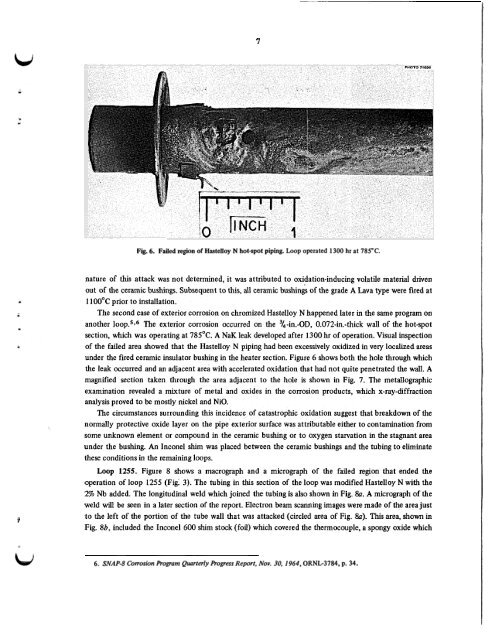
Fig. 6. Failed region <strong>of</strong> Hastelloy N hot-spot piping. Loop operated 1300 hr at 785°C.<br />
nature <strong>of</strong> this attack was not determined, it was attributed <strong>to</strong> oxidation-inducing volatile material driven<br />
out <strong>of</strong> the ceramic bushings. Subsequent <strong>to</strong> this, all ceramic bushings <strong>of</strong> the grade A Lava type were fired at<br />
1100°C prior <strong>to</strong> installation.<br />
The second case <strong>of</strong> exterior corrosion on chromized Hastelloy N happened later in the same program on<br />
another ~ ooP.~~~ The exterior corrosion occurred on the 3/4-in.-OD, O.O72-in.-thick wall <strong>of</strong> the hot-spot<br />
section, which was operating at 785°C. A NaK leak developed <strong>after</strong> 1300 hr <strong>of</strong> operation. Visual inspection<br />
<strong>of</strong> the failed area showed that the Hastelloy N piping had been excessively oxidized in very localized areas<br />
under the fired ceramic insula<strong>to</strong>r bushing in the heater section. Figure 6 shows <strong>both</strong> the hole through which<br />
the leak occurred and an adjacent area with accelerated oxidation that had not quite penetrated the wall. A<br />
magnified section taken through the area adjacent <strong>to</strong> the hole is shown in Fig. 7. The metallographic<br />
examination revealed a mixture <strong>of</strong> metal and oxides in the corrosion products, which x-ray-diffraction<br />
analysis proved <strong>to</strong> be mostly nickel and NiO.<br />
The circumstances surrounding this incidence <strong>of</strong> catastrophic oxidation suggest that breakdown <strong>of</strong> the<br />
normally protective oxide layer on the pipe exterior surface was attributable either <strong>to</strong> contamination from<br />
some unknown element or compound in the ceramic bushing or <strong>to</strong> oxygen starvation in the stagnant area<br />
under the bushing. An Inconel shim was placed between the ceramic bushings and the tubing <strong>to</strong> eliminate<br />
these conditions in the remaining loops.<br />
Loop 1255. Figure 8 shows a macrograph and a micrograph <strong>of</strong> the failed region that ended the<br />
operation <strong>of</strong> loop 1255 (Fig: 3). The tubing in this section <strong>of</strong> the loop was modified Hastelloy N with the<br />
2% Nb added. The longitudinal weld which joined the tubing is also shown in Fig. &. A micrograph <strong>of</strong> the<br />
weld will be seen in a later section <strong>of</strong> the report. Electron beam scanning images were made <strong>of</strong> the area just<br />
<strong>to</strong> the left <strong>of</strong> the portion <strong>of</strong> the tube wall that was attacked (circled area <strong>of</strong> Fig. Sa). This area, shown in<br />
Fig. 8b, included the Inconel 600 shim s<strong>to</strong>ck (foil) which covered the thermocouple, a spongy oxide which<br />
6. SNAP-8 Corrosion Program Quarterly Progress Report, Nov. 30, 1964,ORNL-3784, p. 34.
![Review of Molten Salt Reactor Physics Calculations [Disc 2]](https://img.yumpu.com/21979492/1/190x247/review-of-molten-salt-reactor-physics-calculations-disc-2.jpg?quality=85)


