

Evaluation of hastelloy N alloys after nine years exposure to both a ...
Evaluation of hastelloy N alloys after nine years exposure to both a ...
Evaluation of hastelloy N alloys after nine years exposure to both a ...

Create successful ePaper yourself
Turn your PDF publications into a flip-book with our unique Google optimized e-Paper software.
14<br />
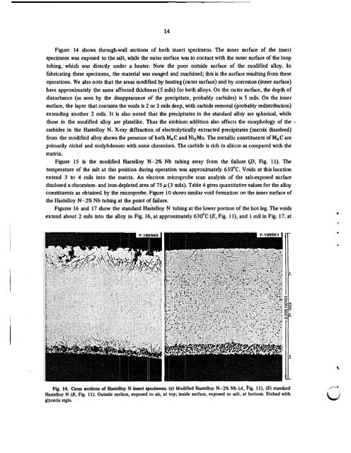
Figure 14 shows through-wall sections <strong>of</strong> <strong>both</strong> insert specimens. The inner surface <strong>of</strong> the insert<br />
specimens was exposed <strong>to</strong> the salt, while the outer surface was in contact with the inner surface <strong>of</strong> the loop<br />
tubing, which was directly under a heater. Note the poor outside surface <strong>of</strong> the modified alloy. In<br />
fabricating these specimens, the material was swaged and machined; this is the surface resulting from these<br />
operations. We also note that the areas modified by heating (outer surface) and by corrosion (inner surface)<br />
have approximately the same affected thickness (5 mils) for <strong>both</strong> <strong>alloys</strong>. On the outer surface, the depth <strong>of</strong><br />
disturbance (as seen by the disappearance <strong>of</strong> the precipitate, probably carbides) is 5 mils. On the inner<br />
surface, the layer that contains the voids is 2 or 3 mils deep, with carbide removal (probably redistribution)<br />
extending another 2 mils. It is also noted that the precipitates in the standard alloy are spherical, while<br />
those in the modified alloy are platelike. Thus the niobium addition also affects the morphology <strong>of</strong> the -<br />
carbides in the Hastelloy N. X-ray diffraction <strong>of</strong> electrolytically extracted .precipitates (matrix dissolved)<br />
from the modified alloy shows the presence <strong>of</strong> <strong>both</strong> M6C and Ni3Mo. The metallic constituents <strong>of</strong> M6C are<br />
primarily nickel and molybdenum with some chromium. The carbide is rich in silicon as compared with the<br />
matrix.<br />
Figure 15 is the modified Hastelloy N-2% Nb tubing away from the failure (D, Fig. 11). The<br />
temperature <strong>of</strong> the salt at this position during operation was approximately 65OoC. Voids at this location<br />
extend 3 <strong>to</strong> 4 mils in<strong>to</strong> the matrix. An electron microprobe scan analysis <strong>of</strong> the salt-exposed surface<br />
disclosed a chromium- and iron-depleted area <strong>of</strong> 75 p (3 mils). Table 4 gives quantitative values for the alloy<br />
constituents as obtained by the microprobe. Figure 10 shows similar void formation on the inner surface <strong>of</strong><br />
the Hastelloy N-2% Nb tubing at the point <strong>of</strong> failure.<br />
Figures 16 and 17 show the standard Hastelloy N tubing at the lower portion <strong>of</strong> the hot leg. The voids<br />
extend about 2 mils in<strong>to</strong> the alloy in Fig. 16, at approximately 63OoC (E, Fig. 1 l), and 1 mil in Fig. 17. at<br />
Fig. 14. Cross sections <strong>of</strong> Hastelloy N insert specimens. (a) Modified Hastelloy N-2% Nb 01, Fig. 11). (b) standard<br />
Hastelloy N (B, Fig. 11). Outside surface, exposed <strong>to</strong> air, at <strong>to</strong>p; inside surface, exposed <strong>to</strong> salt, at bot<strong>to</strong>m. Etched with<br />
glyceria regia.<br />
i
![Review of Molten Salt Reactor Physics Calculations [Disc 2]](https://img.yumpu.com/21979492/1/190x247/review-of-molten-salt-reactor-physics-calculations-disc-2.jpg?quality=85)


