Evaluation of hastelloy N alloys after nine years exposure to both a ...
Evaluation of hastelloy N alloys after nine years exposure to both a ...
Evaluation of hastelloy N alloys after nine years exposure to both a ...
You also want an ePaper? Increase the reach of your titles
YUMPU automatically turns print PDFs into web optimized ePapers that Google loves.
i<br />
i<br />
P<br />
G<br />
- .<br />
r<br />
3<br />
The experiment was started April 11, 1962, and, with only a few minor interruptions, operated until<br />
July 20, 1971. On the day operation was ended, the amperage t6 the loop heaters decreased <strong>to</strong> one-half <strong>of</strong><br />
normal. Investigation revealed that half the main heaters were open and, in addition, grounded (which <strong>of</strong>ten<br />
indicates the presence <strong>of</strong> salt). At this time, all power <strong>to</strong> the loop was shut down. After cool-down, the<br />
insulation and heaters were removed, revealing a small amount <strong>of</strong> salt on the outside <strong>of</strong> the tubing.<br />
During the last few <strong>years</strong>, we planned <strong>to</strong> operate the loop as long as possible <strong>to</strong> provide long-term data<br />
on mass transfer in a fluoride salt, air oxidation <strong>of</strong> Hastelloy N, and corrosion properties <strong>of</strong> various weld<br />
junctions. Thus, the failure provided an end <strong>to</strong> the experiment. In this report, we will discuss the loop<br />
failure, the compatibility <strong>of</strong> the Hastelloy N <strong>alloys</strong> and their welds with the salt, and the air oxidation <strong>of</strong><br />
the alloy. The results <strong>of</strong> this experiment are still quite significant in that recent developments3 have<br />
indicated that certain Hastelloy N <strong>alloys</strong> containing additions <strong>of</strong> Ti, Hf, Nb, and Zr have good mechanical<br />
properties (better than standard Hastelloy N) <strong>after</strong> being irradiated at 760°C. Thus, the possibility <strong>of</strong> using<br />
a modified alloy similar <strong>to</strong> the one tested in this experiment still exists.<br />
EXPERIMENTAL PROCEDURE AND MATERIALS<br />
Figure 2 is a pho<strong>to</strong>graph <strong>of</strong> a typical thermal convection loop with'heaters and thermocouples installed<br />
but without insulation. Thermocouples are located at the <strong>to</strong>p <strong>of</strong> the hot and cold leg, at the bot<strong>to</strong>m <strong>of</strong> the<br />
cold leg, at the insert specimen locations, and over the modified Hastelloy N tubing. A schematic view <strong>of</strong><br />
the loop is shown in Fig. 3. The parts <strong>of</strong> the loop we will refer <strong>to</strong>'are the hot leg (heated vertical tubing),<br />
cold leg (unheated vertical tubing), upper crossover, and lower crossover. The major portion <strong>of</strong> the loop was<br />
constructed <strong>of</strong> 3/8-in. sched 10 standard Hastelloy N pipe (approx 0.675 in. OD) from heat No. Y-8460<br />
(Superior Tube) and an experimental heat specified as Haynes SP-19. The <strong>to</strong>p 9 in. <strong>of</strong> the hot leg contained<br />
two tube inserts. The <strong>to</strong>p insert was Hastelloy N-2% Nb, and the bot<strong>to</strong>m one was standard Hastelloy N.<br />
The inserts were 3-inAong cylinders, 0.595 in. OD, 0.025 in. wall, which were fitted in<strong>to</strong> machined<br />
portions <strong>of</strong> the loop tubing, thus retaining the same flow cross section throughout the 1oop.The next Gin.<br />
section <strong>of</strong> the hot leg was Hastelloy N-2% Nb tubing, and the remainder <strong>of</strong> the loop was standard<br />
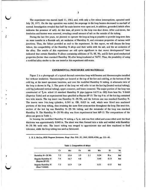
Hastelloy N. The Hastelloy N-2% Nb alloy was from experimental heat MP-13. The compositions <strong>of</strong> the<br />
<strong>alloys</strong> are given in Table 1.<br />
In forming the modified Hastelloy N tubing, a '&-in. slab was first rolled and cross-rolled until the final<br />
thickness 'was approximately 0.040 in. The sheet was then formed in<strong>to</strong> a tube and welded with Hastelloy<br />
N-2% Nb weld wire. The insert tubing was swaged <strong>to</strong> approximate size and then machined <strong>to</strong> final<br />
<strong>to</strong>lerance, while the loop tubing was used as fabricated.<br />
3. H. E. McCoy,MSR bogram Semiannu. eogr. Rep. Feb. 28,1969,ORNL4396, pp. 235-40.<br />
-<br />
Table 1. Composition <strong>of</strong> <strong>alloys</strong><br />
Cr Mo Fe Nb Mn Si Ni<br />
Hastelloy N-2% Nb 7.5 15.4 3.9 2.1 0.54 N.a. Bid<br />
Regular Hastelloy N 7.4 16.7 4.8 0.48 0.13 Bid<br />
(Haynes SP-19)<br />
Regular Hastelloy N 1.3 15.9 2.4<br />
(Heat Y-8460)<br />
0.31 0.15 Bal


![Review of Molten Salt Reactor Physics Calculations [Disc 2]](https://img.yumpu.com/21979492/1/190x247/review-of-molten-salt-reactor-physics-calculations-disc-2.jpg?quality=85)


