FM-TX2-XXX FM-RX2-XXX - Netzmafia
FM-TX2-XXX FM-RX2-XXX - Netzmafia
FM-TX2-XXX FM-RX2-XXX - Netzmafia

Create successful ePaper yourself
Turn your PDF publications into a flip-book with our unique Google optimized e-Paper software.
Module test circuits<br />
<strong>FM</strong> TRANSMITTER & RECEIVER <strong>FM</strong>-<strong>TX2</strong>-<strong>XXX</strong><br />
MODULES. (2ND GENERATION) <strong>FM</strong>-<strong>RX2</strong>-<strong>XXX</strong><br />
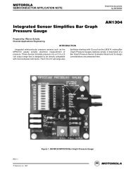
fig.5: <strong>TX2</strong> test circuit<br />
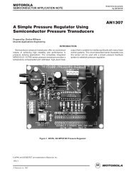
fig.6: <strong>RX2</strong> test circuit<br />
∗ The PNP transistor enables a CMOS compatible Carrier Detect signal to be derived from pin 3. If no CD signal required<br />
pin 3 should be connected directly to pin 5 (Vcc)<br />
Module mounting considerations<br />
The modules may be mounted horizontally or vertically on an area of ground plane preferably<br />
close to the antenna to minimise feed length. The receiver and it’s antenna should be kept away<br />
from sources of interference (micro’s, SMPS etc.). The modules may be potted if required in a<br />
viscous compound which can not enter the screen can..<br />
Warning: Do NOT wash the modules. They are not hermetically sealed.<br />
DS000022 Rev D July ‘99 ©1999 REG No 277 4001, ENGLAND. Page 6