Touch Screen-Wetterstation Modell WS-3600 - Technoline
Touch Screen-Wetterstation Modell WS-3600 - Technoline
Touch Screen-Wetterstation Modell WS-3600 - Technoline

You also want an ePaper? Increase the reach of your titles
YUMPU automatically turns print PDFs into web optimized ePapers that Google loves.
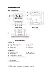
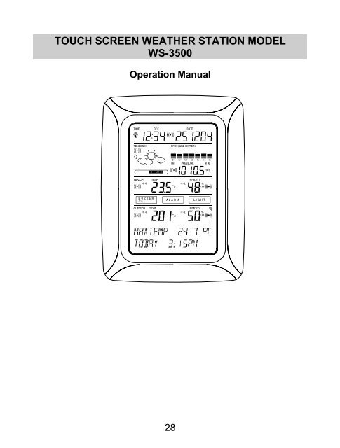
TOUCH SCREEN WEATHER STATION MODEL<br />
<strong>WS</strong>-3500<br />
Operation Manual<br />
28
Table of Contents<br />
1 ...................... General<br />
2 ....................... Important <strong>Touch</strong> <strong>Screen</strong> Operating Notes generally applicable<br />
3 ...................... Putting into Operation<br />
3.1 ................ Wiring the System<br />
3.2 ................ Power Supply<br />
3.2.1.......... Batteries<br />
3.2.2.......... AC/DC Mains Adapter<br />
3.2.3.......... Cable Connection<br />
3.3 ................ System Start<br />
3.4 ................ Placement<br />
4 ...................... Setting Up<br />
5 ...................... Display of stored Min/Max Values and Alarm Value Settings<br />
6 ...................... Radio Controlled DCF77 Clock<br />
7 ...................... Weather Tendency<br />
8 ...................... Air Pressure History<br />
9 ...................... Operating and Setting of various Functions<br />
9.1 ................ Air Pressure<br />
10 .................... Additional Information to Function Outdoor Temperature<br />
11 .................... Operating and Setting of Functions Backlight, Buzzer and<br />
Alarm section<br />
11.1 .............. EL Backlight<br />
11.2 .............. Buzzer<br />
11.3 .............. Alarm<br />
12 .................... PC Connection<br />
12.1 .............. Data Storage<br />
12.2 .............. Data Recall<br />
12.3 .............. Connections and Software<br />
13 .................... Technical Data<br />
13.1 .............. Outdoor Data<br />
13.2 .............. Data Transmission by 433 MHz Signal<br />
13.3 .............. Data Transmission by Cable<br />
13.4 .............. Indoor Data<br />
13.5 .............. Power Supply<br />
13.6 .............. PC Connection<br />
13.7 ........... Dimensions<br />
14 ................. Liability Disclaimer<br />
29
1 General<br />
Important Note:<br />
Before inserting batteries to the units, please<br />
carefully read the operation manual.<br />
The shipping contents of the <strong>Touch</strong> <strong>Screen</strong> Weather Station <strong>WS</strong>-3500<br />
include a Base Station (Receiver), a Thermo-Hygro Sensor (433 MHz<br />
Transmitter), the respective Connecting Cables, an AC/DC Mains<br />
Adapter and a PC Software Package on CD-ROM.<br />
The Base Station is equipped with a <strong>Touch</strong> <strong>Screen</strong> LCD Monitor and<br />
allows by use of comprehensive menu control the display of a vast<br />
variety of time and weather data (from top to bottom):<br />
Radio Controlled Time (Time)<br />
Calendar (Date)<br />
Weather Forecast (Tendency)<br />
Air Pressure and Air Pressure History (Pressure, Pressure<br />
History)<br />
Indoor Temperature and Humidity (Indoor Temp, Humidity)<br />
Outdoor Temperature and Humidity (Outdoor Temp, Humidity)<br />
Furthermore the display of a number of additional data can be realised<br />
by use of certain switching combinations (see further down).<br />
Note: In case the menu is used all these indications are temporarily<br />
replaced by the menu steps directly operable from the text section.<br />
As an important feature exceeding the display on the LCD<br />
Monitor the Weather Station allows by cable and software the<br />
readout of all measured and displayed time and weather data in<br />
form of complete history data sets, their processing and graphic<br />
presentation on a PC as well as their tie on to Internet Web Sites.<br />
30
2 Important <strong>Touch</strong> <strong>Screen</strong> Operating Notes generally<br />
applicable<br />
All actions and functions of the Weather Station are started on the<br />
<strong>Touch</strong> <strong>Screen</strong> by slightly touching (not pressing!) the switching areas<br />
appearing in star (٭) symbols (only in the text section at the bottom of<br />
the LCD) or the displayed values respectively.<br />
The setting of functions, values and units is in all modes performed by<br />
use of the switching areas ٭ON٭ or ٭OFF٭, ٭UP٭ or ٭DOWN٭ or by<br />
direct unit selection.<br />
Advancing to any next respective menu step with ٭NEXT٭, leaving or<br />
terminating all respective modes with ٭EXIT٭.<br />
Every programming step activated by touching a switching area on the<br />
<strong>Touch</strong> <strong>Screen</strong> is being acknowledged by an acoustic signal (with<br />
buzzer switched ON).<br />
If during any process previously activated by use of the <strong>Touch</strong> <strong>Screen</strong><br />
no further action is activated for about 30 seconds the active process<br />
is automatically terminated and switched back to the normal display<br />
mode (automatic time out).<br />
31
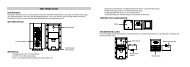
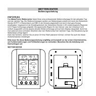
<strong>Touch</strong> screen "switching area" on LCD:<br />
Time section<br />
Weather<br />
Tendency<br />
section<br />
Indoor<br />
Temperature<br />
section<br />
Buzzer selection key<br />
Alarm history selection<br />
Outdoor temperature<br />
section<br />
3 Putting into Operation<br />
Date section<br />
Pressure History<br />
section<br />
Pressure section<br />
Indoor humidity<br />
section<br />
Backlight section<br />
key<br />
Outdoor humidity<br />
section<br />
Text Display<br />
(Set up Display)<br />
At first it is to decide whether battery supply or mains supply (AC/DC<br />
mains adapter included) will be used to operate the system. Both<br />
methods allow the connection of Thermo-Hygro Sensor and Base<br />
Station by cable or by 433 MHz radio signal.<br />
Note: When putting the Weather Station into operation it is important<br />
to tentatively perform in close proximity (e.g. on a table) a complete<br />
wiring and set up of the system in the configuration of its prospective<br />
use. This measure serves to test all components for correct function<br />
before placing and mounting them at their final destinations.<br />
32
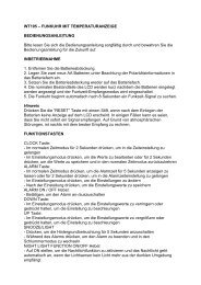
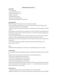
3.1 Wiring the System<br />
AC/DC-Adapter<br />
Thermo-Hygro-Sensor<br />
PC COM Port cable<br />
OUTDOOR<br />
TX<br />
Wireless<br />
Transmission<br />
Direct cable<br />
connection<br />
The direct cable connection of Thermo-Hygro Sensor and Base<br />
Station can be used in case that:<br />
the flexibility of 433 MHz radio transmission is not needed and<br />
data transmission absolutely free of any environmental interferences is<br />
wanted.<br />
3.2 Power Supply<br />
The provision of power to the Weather Station can be performed by<br />
use of batteries or by AC/DC mains adapter.<br />
33
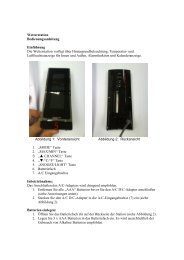
3.2.1 Batteries:<br />
First insert two Type AA 1.5 V batteries into the battery compartment<br />
of the Thermo-Hygro-Sensor.<br />
Immediately following this insert three Type AA 1.5V batteries into<br />
the battery compartment of the <strong>Touch</strong> <strong>Screen</strong> Weather Station.<br />
Please help in the preservation of the environment and<br />
return used batteries to an authorized depot.<br />
3.2.2 AC/DC Mains Adapter:<br />
Firstly also insert two Type AA 1.5 V batteries into the battery<br />
compartment of the Thermo-Hygro-Sensor.<br />
Immediately following this connect the AC/DC mains adapter to the<br />
Base Station and then plug it into a regular mains outlet.<br />
Note: In both cases it is important to observe this order of succession<br />
since the Sensor will send an identification code which has to be<br />
received and stored by the Base Station within the first few minutes of<br />
operation.<br />
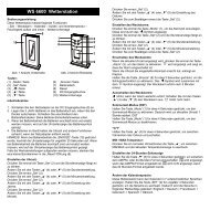
34<br />
OUTDOOR<br />
TX
After doing this full operation of the entire Weather Station System is<br />
ensured.<br />
3.2.3 Cable Connection:<br />
One further feature of the direct cable connection mentioned in Item<br />
3.1 above is that in case of AC/DC adapter operation power is<br />
provided not only to the Base Station but to the Thermo-Hygro Sensor<br />
as well by just this AC/DC adapter.<br />
Note: System operation with cable connection while at the same<br />
time providing power to the Base Station solely by batteries is not<br />
recommended due to the considerably higher power consumption. The<br />
batteries may however remain in the unit for emergency supply in case<br />
of a power failure.<br />
A change from cable operation to 433 MHz radio transmission or vice<br />
versa is possible in any case since the Weather Station will recognize<br />
this change and will automatically switch to the appropriate operating<br />
mode.<br />
3.3 System Start<br />
After inserting the batteries respectively connecting the AC/DC adapter<br />
the LCD of the Weather Station will for a few seconds display all<br />
possible display segments for checking.<br />
Immediately after this the unit will enter the so called play mode during<br />
which for about 15 minutes all measured and received weather data<br />
are being switched through, updated and displayed. During this time<br />
period there will be no reception of the DCF77 time information.<br />
Note: The play mode phase allows the user of the Weather Station<br />
to check all cables for correct connection and all components for<br />
correct function.<br />
After completing the play mode the <strong>Touch</strong> <strong>Screen</strong> Weather Station will<br />
automatically switch to the normal display mode from which all further<br />
settings can be performed by the user. At this point of time the unit will<br />
also automatically start reception of the DCF77 time information.<br />
35
Important Note:<br />
Reception of the radio-controlled time information will only take<br />
place after completion of the play mode (approx. 15 minutes). In<br />
case the user wants to start the system without waiting for<br />
completion of the play mode it can be terminated prematurely by<br />
once touching the TIME display in the upper left corner of the<br />
LCD.<br />
Prior to manual setting or reception of radio-controlled time<br />
information there will be no recording of weather history data.<br />
3.4 Placement<br />
After the Weather Station has been checked for correct function with<br />
regard to the above points and found fit, the mounting of the system<br />
components can take place. It must be ensured however that all<br />
components work properly together at their chosen mounting or<br />
standing locations. If e.g. there appear to be problems with the 433<br />
MHz radio transmission they can mostly be overcome by slightly<br />
moving the mounting locations.<br />
Note: Commonly the radio communication between receiver and<br />
transmitter in the open field reaches distances of about maximum 100<br />
meter providing that there are no interfering obstacles such as<br />
buildings, trees, vehicles, high voltage lines, etc.<br />
Radio interferences as they are created by PC screens, radios or TV<br />
sets can in bad cases entirely cut off radio communication. Please<br />
take this into consideration when choosing standing or mounting<br />
locations.<br />
4 Setting Up:<br />
Note: Because of the default settings already determined by the<br />
manufacturer it may not be necessary for the majority of users to<br />
perform - outside possibly the Relative Air Pressure (see further down)<br />
- any further basic settings. Changes however can easily be realized if<br />
desired.<br />
For basic settings the following menu is started by touching the <strong>Touch</strong><br />
<strong>Screen</strong> in the center of the text display (last two lines on the LCD).<br />
<strong>Touch</strong>ing the display ٭SETUP٭ will enter the setup mode.<br />
36
The basic settings can now be performed in the following successive<br />
order:<br />
LCD Contrast Contrast can be set in 8 steps from 0 to 7 (Default<br />
4).<br />
Time Zone Time Zones can be set in the range from -12 to +12<br />
hours (Default 0 hours for Central Europe).<br />
DCF77 Radio Controlled Clock (RCC) ON/OFF. In setting “OFF“<br />
the clock is operating as a normal Quartz clock (Default RCC ON).<br />
12/24 hour Time Display Format (Default 24 h Format).<br />
37
Units<br />
Temperature Display (Temp) in °C or °F (Default °C).<br />
Air Pressure (Press) in hPa or inHg (Default hPa).<br />
Relative Air Pressure (Rel. Pressure) To be set to the locally valid<br />
reference air pressure with regard to the local height above sea level<br />
(Default 1013,0 hPa).<br />
Weather Tendency (Tendency) Setting to a definite switching<br />
threshold (2 hPa to 4 hPa) for a change in display of weather icons<br />
(Default 3 hPa).<br />
Storm Warning (Storm) Setting to a definite switching threshold for<br />
storm warning display at a decrease of air pressure from 3 hPa to 9<br />
hPa over 6 hours (Default 5 hPa).<br />
38
Activate/Deactivate storm warning alarm with ٭ON٭ / ٭OFF٭ resp.<br />
(Default OFF).<br />
Relearn Mode (Relearn Tx) Allows to newly recognize the outdoor<br />
transmitter (e. g. after a battery change in the transmitter) without the<br />
necessity of a comprehensive re-setup of all system components<br />
Acknowledge with ٭CONFIRM٭.<br />
Default Settings (Factory Reset) Allows to clear all weather data<br />
form non-volatile buffer memory (EEPROM) and reset of all set and/or<br />
stored values to the factory settings set prior to shipment<br />
Acknowledge with ٭CONFIRM٭.<br />
Note:<br />
It will take about 5 minutes for the factory reset process. During this<br />
period, the text “Factory Reset In Progress” will be shown. After the<br />
reset process is finished, the LCD will switch off and the text “Remove<br />
Battery” will be displayed. Remove the battery and perform system<br />
start again. See “3 - Putting in Operation” paragraph.<br />
Leaving the basic settings procedure (Setup Mode) with ٭EXIT٭.<br />
39
5 Display of stored Min/Max Values and Alarm Value<br />
Settings<br />
Named values are in each case upon recall being simultaneously<br />
displayed and flashing in their respective display sections.<br />
To recall named measuring and alarm values the menu shown below<br />
will have to be activated by touching the <strong>Touch</strong> <strong>Screen</strong> in the center of<br />
the text display section (last two lines at the bottom of the LCD). The<br />
display of the values is started by touching the displays ٭MINMAX٭ or<br />
٭ALARMS٭ resp.<br />
The continuance of the recalling process is essentially self-<br />
explanatory.<br />
With ٭MINMAX٭ the below shown menu step is activated, which in<br />
return leads to the displays of the stored Min/Max values by use of<br />
٭MIN٭ / ٭MAX٭ resp., which on their part again can be directly<br />
selected.<br />
Note: During individual displays of the stored Min/Max values of<br />
particular weather data, the top line of the LCD screen will<br />
automatically display the time and date of the record.<br />
The following menu item will appear upon touching the display<br />
٭ALARMS٭ and will analog to the last described step lead through<br />
٭LO AL٭ resp. ٭HI AL٭ to the<br />
40
displays of the set low resp. high alarm values, which on their part<br />
again can be directly selected.<br />
Because of the constant access to the respective opposite menu item<br />
٭MINMAX٭ resp. ٭ALARMS٭ it is moreover possible at any time to<br />
toggle between the MIN/MAX and ALARMS value displays.<br />
Any action can immediately be terminated through ٭EXIT٭.<br />
6 Radio Controlled DCF77 Clock<br />
The Radio Controlled DCF77 Clock is normally controlled by the radio<br />
signal of the DCF77 time code transmitter and will thus set time and<br />
date automatically. Under bad reception conditions however both can<br />
be set manually as follows:<br />
Setting the Time<br />
The action is started by touching the time display in the TIME section<br />
of the <strong>Touch</strong> <strong>Screen</strong>.<br />
Start ٭TIME٭ in the menu section (last two lines on the LCD).<br />
Set the hours and minutes. Leave the mode with ٭EXIT٭ or wait for<br />
automatic time-out.<br />
41
Setting the Date<br />
The action is started by touching the date display in the DATE section<br />
of the <strong>Touch</strong> <strong>Screen</strong>.<br />
Set the year, month and date of day. Leave the mode with ٭EXIT٭.<br />
Note:<br />
By twice touching the DATE section the display will toggle between the<br />
following:<br />
Date in DD.MM.YY format (24 hour time format) or Date in<br />
MM.DD.YY format (12 hour time format)<br />
Weekday (Eng. abbrev.), Date of Day, Month (24 hour<br />
format) or Weekday, Month, Date of Day (12 hour time<br />
format)<br />
Seconds<br />
Set Wake-up Alarm Time<br />
Setting of Wake-up Alarm<br />
The action is started by touching the time display in the TIME section.<br />
Start ٭ALARM٭ in the menu section (last two lines on the LCD).<br />
Set hours and minutes of the wake-up time. Leave the mode with<br />
٭EXIT٭.<br />
42
Note:<br />
The wake-up alarm is activated/deactivated by twice touching the<br />
TIME section. Here the alarm symbol ((( ))) will show or disappear<br />
after ٭EXIT٭ (or automatic time-out).<br />
When the alarm sounds, user may "touch" any section on the LCD<br />
to stop the alarm.<br />
7 Weather Tendency<br />
Call up the tendency display by touching the weather symbol in the<br />
TENDENCY section.<br />
The text section (last two lines on the LCD) will show since when (with<br />
time and date) the weather condition corresponds to the presently<br />
displayed weather symbol Sunny, Fair (Cloudy with sunny intervals) or<br />
Rainy.<br />
Note:<br />
Up and down arrow indicate weather tendency<br />
Advanced storm warning is displayed by Rainy symbol with a<br />
flashing down arrow<br />
Every minute, when a new pressure reading is obtained, this<br />
value is compared to pressure readings from last 2 hours and<br />
43
the biggest resulting difference is displayed in the difference<br />
barometer.<br />
8 Air Pressure History (Pressure History)<br />
The air pressure history shows the progress of the air pressure over a<br />
time period of 24 or 72 hours in form of a 7-step bar graph, where the<br />
length of the utmost right bar represents the present air pressure and<br />
the remaining bars show the progress of the air pressure with regard<br />
to the present air pressure.<br />
Note: The time resolution of the bar graph can be changed from fine<br />
(0 to -24 h) to coarse (0 to -72 h) and back by once touching the<br />
PRESSURE HISTORY section.<br />
9 Operating and Setting of the following Functions:<br />
Air Pressure (Pressure), Relative and Absolute<br />
Indoor Temperature (Indoor Temp)<br />
Indoor Humidity (Indoor Humidity)<br />
Outdoor Temperature (Outdoor Temp), Dew Point<br />
Outdoor Humidity (Outdoor Humidity)<br />
Important Note!<br />
Since the operating procedures and settings are similar for all<br />
steps to be carried out on the <strong>Touch</strong> <strong>Screen</strong> Weather Station for<br />
above functions, here, the procedure shall be explained only<br />
once by means of the following example “Air Pressure”.<br />
44
9.1 Air Pressure (Pressure)<br />
Example for Activating the Displays of Stored Maximum Values<br />
Call up the menu on the text section by touching the PRESSURE<br />
section.<br />
Start with ٭MAX٭ in the menu section.<br />
Note: Display of the stored minimum values is from here possible<br />
through ٭MIN٭ analog to this example.<br />
Display of stored value. Proceed with ٭MAX PRESSURE٭.<br />
Resetting of the displayed value to the present value with<br />
٭CONFIRM٭.<br />
Without resetting advance with ٭EXIT٭.<br />
End of Example<br />
45
Example for Setting of Alarms by means of the HI Alarms<br />
As in the example above here too call up the menu on the text section<br />
by touching the PRESSURE section.<br />
Start with ٭ALARM٭ in the menu section.<br />
Proceed with ٭HI AL٭ in the menu section.<br />
Note: Setting of the LO alarms is from here possible through ٭LO AL٭<br />
analog to this example.<br />
Setting of high alarm value with ٭UP٭ or ٭DOWN٭.<br />
Proceed with ٭ON/OFF٭.<br />
Activate or deactivate the alarm with ٭ON٭ or ٭OFF٭.<br />
Terminate with ٭EXIT٭.<br />
Note:<br />
Activation or deactivation of the alarm (Display or deletion of the ((( )))<br />
symbol) only pertains to the respective presently displayed value.<br />
46
End of Example<br />
Note:<br />
Twice touching the PRESSURE section toggles the displays of the<br />
Relative (rel) and Absolute (abs) air pressure.<br />
All setting and display facilities only pertain to the respective presently<br />
displayed value.<br />
10 Additional Information to Function Outdoor<br />
Temperature (Outdoor Temp)<br />
Note:<br />
By twice touching the OUTDOOR section the display will toggle<br />
between the following:<br />
Outdoor Temperature (Outdoor Temp)<br />
Dew Point<br />
All setting and display facilities only pertain to the respective presently<br />
displayed value.<br />
11 Operating and Setting of Functions EL Backlight<br />
(Light), Buzzer and Alarm<br />
11.1 EL Backlight (Light)<br />
For better readability of the LCD the EL backlight can be switched ON<br />
or OFF by once touching the LIGHT section. In condition ON the<br />
backlight will be switched on for approximately 15 seconds every time<br />
any one of the LCD sections is being touched.<br />
The switching condition (Enabled/Disabled) is shown in the text<br />
section for about 30 seconds.<br />
Note:<br />
In case the <strong>Touch</strong> <strong>Screen</strong> Weather Station is battery operated the<br />
repeated use of the EL backlight will result in a considerable decrease<br />
47
of battery lifetime. It is thus recommended to either operate the<br />
Weather Station on the included AC/DC adapter or entirely deactivate<br />
the EL backlight (see above).<br />
11.2 Buzzer<br />
The buzzer for the acoustic acknowledgement or alarm signals of the<br />
Weather Station can be switched ON or OFF by touching the BUZZER<br />
section.<br />
The switching condition ON or OFF is displayed directly in the<br />
BUZZER section as well as for about 30 seconds in the text section<br />
(Enabled/Disabled).<br />
11.3 Alarm<br />
Upon touching the ALARM display key will – numbered and sorted<br />
according to the time of appearance – with ٭NEXT٭ all those set and<br />
activated alarms (outside the wake-up alarm) be displayed that have<br />
reached an alarm condition since their last deletion.<br />
Here for every respective alarm the time and date of appearance can<br />
be displayed by touching ٭ALARM٭.<br />
12 PC Connection<br />
As an important feature exceeding the mere display on the <strong>Touch</strong><br />
<strong>Screen</strong> the Weather Station allows the read-out of all measured<br />
and displayed time and weather data in form of complete history<br />
data sets on a PC.<br />
12.1 Data Storage<br />
For a comprehensive weather history the Base Station allows the<br />
internal storage of up to 1750 complete sets of weather data with time<br />
and date. These data sets are being stored in non-volatile ring buffer<br />
memory (EEPROM) and will not be lost even in case of an interruption<br />
of power supply (e. g. change of batteries).<br />
In case the memory capacity of the Weather Station is exhausted the<br />
oldest data sets stored will be overwritten by the new ones entered.<br />
48
12.2 Data Recall<br />
The weather data stored can only be read out, processed and<br />
displayed by means of a PC. Also the settings of the storing intervals<br />
from 1 minute to 24 hours for the storage of data sets can only be<br />
performed by means of a PC.<br />
12.3 Connections and Software<br />
The wiring between Weather Station and PC takes place by means of<br />
an included COM port cable. Furthermore the “Heavy Weather Pro“<br />
software package also included in the shipping contents must be<br />
installed on the PC.<br />
This software allows the display of all present weather data with<br />
graphic symbols. It further allows the display, storage and printing of<br />
history data sets, whose volume exceeding the maximum 1750 data<br />
sets of the Weather Station is only limited by the capacity of the PC’s<br />
main memory.<br />
Furthermore the present weather data can be tied on to web sites by<br />
means of the “Web Publisher“ software. History data can be displayed<br />
as diagrams and graphs by means of the “Heavy Weather Pro“<br />
software.<br />
Important note:<br />
For further details to the subject “PC Connection“ and<br />
Program utilisation, please see the "Help" File (under the<br />
Question mark button in menu bar) of the Heavy Weather<br />
Program. (The Wind and Rain measurements are not<br />
applicable to the model <strong>WS</strong>-3500.)<br />
49
13 Technical Data<br />
13.1 Outdoor Data:<br />
Transmission Range in Open Field: ...........100 m max.<br />
Measuring Intervals Outdoor Data:.............every 128 s<br />
Temperature Range: -40 °C to +59.9 °C (Display<br />
“OFL” outside this range)<br />
Resolution: .................................................0.1 °C<br />
Measuring Range Rel. Humidity:...............1% to 99%<br />
Resolution: .................................................1%<br />
13.2 Data Transmission by 433 MHz Signal:<br />
Measuring Intervals Thermo-Hygro Sensor: 128 s<br />
13.3 Data Transmission by Cable:<br />
Measuring Intervals Thermo-Hygro Sensor: 128 s<br />
13.4 Indoor Data:<br />
Measuring Intervals Indoor Data: ...............every 20 s<br />
Temperature Range: ..................................-40 °C to +59.9°C (Display<br />
“OFL” outside this range)<br />
Resolution: .................................................0.1 °C<br />
Measuring Range Rel. Humidity:................1% to 99%<br />
Resolution: .................................................1%<br />
Measuring Range Air Pressure: .................300 hPa to 1099 hPa<br />
Resolution: .................................................0.1 hPa<br />
Alarm Duration: ..........................................about 2 minutes<br />
13.5 Power Supply:<br />
Base Station:<br />
Batteries: ....................................................3 x 1.5 V Batteries Type<br />
AA, IEC LR6 (Alkaline<br />
Batteries recommended,<br />
Life Cycle without EL<br />
backlight approx. 1 year).<br />
When batteries require<br />
50
eplacement for the base<br />
station, the low battery<br />
indicator will light up on the<br />
LCD.<br />
or Mains Voltage: .......................................AC/DC Adapter INPUT<br />
230VAC / 50Hz (use only<br />
the included Mains<br />
Adapter. Recommended<br />
for PC Connection and<br />
frequent use of EL<br />
Backlight)<br />
Thermo-Hygro-Sensor:<br />
Batteries: ...................................................2 x 1.5 V Batteries Type AA,<br />
IEC LR6 (Alkaline Batteries<br />
recommended, Life Cycle<br />
approx. 1 year)<br />
or ................................................................Power provided via Cable<br />
from the Base Station by<br />
using the AC/DC Adapter<br />
13.6 PC Connection:<br />
Wiring: ........................................................COM Port Cable (included)<br />
Data Processing: ........................................by PC only<br />
Software: ....................................................“Heavy Weather Pro“<br />
(included)<br />
Storage Intervals: .......................................1 min through 24 h,<br />
settable<br />
Data Volume:<br />
Base Station: ..............................................1750 Data Sets max. in<br />
Ring Buffer EEPROM<br />
PC: .............................................................Volume of Main Memory<br />
max.<br />
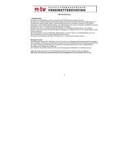
13.7 Dimensions:<br />
Base Station: .............................................. 142 x 185 x 32.2 mm<br />
Thermo-Hygro-Sensor:............................... 56.2 x 70.5 x 137 mm<br />
51
14 LIABILITY DISCLAIMER:<br />
The electrical and electronic wastes contain hazardous<br />
substances. Disposal of electronic waste in wild country and/or in<br />
unauthorized grounds strongly damages the environment.<br />
Please contact your local or/and regional authorities to retrieve the<br />
addresses of legal dumping grounds with selective collection.<br />
All electronic instruments must from now on be recycled. User<br />
shall take an active part in the reuse, recycling and recovery of the<br />
electrical and electronic waste.<br />
The unrestricted disposal of electronic waste may do harm on<br />
public health and the quality of environment.<br />
As stated on the gift box and labeled on the product, reading the<br />
“User manual” is highly recommended for the benefit of the user.<br />
This product must however not be thrown in general rubbish<br />
collection points.<br />
The manufacturer and supplier cannot accept any responsibility<br />
for any incorrect readings and any consequences that occur<br />
should an inaccurate reading take place.<br />
This product is designed for use in the home only as indication of<br />
the temperature.<br />
This product is not to be used for medical purposes or for public<br />
information.<br />
The specifications of this product may change without prior notice.<br />
This product is not a toy. Keep out of the reach of children.<br />
No part of this manual may be reproduced without written<br />
authorization of the manufacturer.<br />
R&TTE Directive 1999/5/EC<br />
Summary of the Declaration of Conformity : We hereby declare that this<br />
wireless transmission device does comply with the essential requirements of<br />
R&TTE Directive 1999/5/EC.<br />
52