AN1307 Application Note - Netzmafia
AN1307 Application Note - Netzmafia
AN1307 Application Note - Netzmafia

You also want an ePaper? Increase the reach of your titles
YUMPU automatically turns print PDFs into web optimized ePapers that Google loves.
MPX2XXX<br />
+5 V<br />
3 2<br />
4 1<br />
RG<br />
IC1 — MC33079<br />
RG — 10K POT<br />
3<br />
2<br />
1M<br />
1M<br />
6<br />
5<br />
+<br />
–<br />
4<br />
IC1A<br />
IC1B<br />
11<br />
1<br />
7<br />
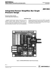
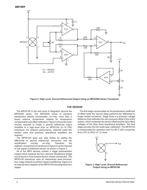
Figure 2. High Level, Ground Referenced Output Using an MPX2000 Series Transducer<br />
The MPX5100 is the next level of integration beyond the<br />
MPX2000 series. The MPX2000 series of pressure<br />
transducers already incorporates, on–chip, more than a<br />
dozen external components needed for temperature<br />
compensation and offset calibration. Figure 2 shows the basic<br />
circuitry required to create a ground referenced output<br />
amplified to a high–level from an MPX2100 (0–15 PSI)<br />
transducer. For optimum performance, matched metal film<br />
resistor pairs and precision operational amplifiers are<br />
required.<br />
The MPX5100 goes one step further by adding the<br />
differential to ground referenced conversion and the<br />
amplification circuitry on–chip. Therefore, the<br />
eighteen–component circuit shown in Figure 2 can be reduced<br />
to one signal–conditioned sensor, as shown in Figure 3.<br />
All of the MPX devices contain a single piezoresistive<br />
implant which replaces the four–element Wheatstone bridge<br />
circuit found in most semiconductor–based transducers. The<br />
MPX5100 transducer uses an interactively laser–trimmed,<br />
four–stage network to perform signal conditioning. Figure 4 is<br />
an internal block diagram of the MPX5100 showing these four<br />
stages.<br />
–<br />
+<br />
C1<br />
THE SENSOR<br />
2 Motorola Sensor Device Data<br />
100K<br />
100K<br />
100K<br />
10<br />
9<br />
100K<br />
+<br />
–<br />
100K<br />
14<br />
IC1C<br />
IC1D<br />
8<br />
10K<br />
–<br />
+<br />
13<br />
12<br />
+5 V<br />
2K<br />
10K<br />
2K<br />
Vout<br />
The first stage compensates for the temperature coefficient<br />
of offset while the second stage performs the differential to<br />
single–ended conversion. Stage three is a precision voltage<br />
reference that calibrates the zero pressure offset of the entire<br />
system, which comprises the sensor offset and the input offset<br />
voltages of the other three operational amplifiers. The final<br />
stage provides the full–scale span calibration. The MPX5100<br />
is compensated for operation over 0 to 85°C with a response<br />
time (10% to 90%) of 1.0 msec.<br />
+5 V<br />
3<br />
1<br />
2<br />
Vout<br />
Figure 3. High Level, Ground Referenced<br />
Output Using an MPX5100