AN1307 Application Note - Netzmafia
AN1307 Application Note - Netzmafia
AN1307 Application Note - Netzmafia

Create successful ePaper yourself
Turn your PDF publications into a flip-book with our unique Google optimized e-Paper software.
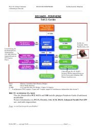
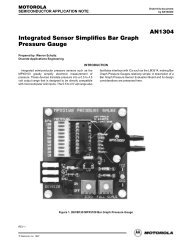
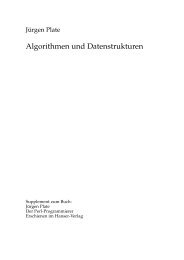
Figure 5 is a block diagram of a simple pressure regulator<br />
feedback system. The motor/pump is used to fill a reservoir as<br />
required. The pressure created in this reservoir is monitored<br />
with a gauge and fed back to the MPX5100 sensor. The sensor<br />
provides an output voltage to the Motor Drive Circuitry which<br />
is proportional to the monitored pressure.<br />
PRESSURE<br />
PORT<br />
SENSOR<br />
PRESSURE<br />
SELECT<br />
CIRCUITRY<br />
+12 Vdc<br />
GND<br />
3<br />
1<br />
2<br />
MOTOR<br />
DRIVE<br />
CIRCUITRY<br />
MOTOR/PUMP<br />
Figure 5. System Block Diagram<br />
+ C1<br />
220<br />
Sout<br />
XDCR1<br />
MPX5100<br />
FWD/REV<br />
S1<br />
R11<br />
3900<br />
R12<br />
10K<br />
R13<br />
330<br />
Sgnd<br />
R5<br />
10K<br />
3<br />
IC2<br />
78L05<br />
VI G<br />
N<br />
VO 1<br />
D C4<br />
2<br />
1.0<br />
C2<br />
0.005<br />
R8<br />
10K<br />
3<br />
2<br />
MC33033<br />
BRUSHLESS<br />
MOTOR CONTROLLER<br />
+<br />
–<br />
1<br />
2<br />
3<br />
4<br />
5<br />
6<br />
7<br />
8 9<br />
10<br />
+12<br />
8<br />
IC1<br />
BT<br />
AT<br />
F/R<br />
HA<br />
HB<br />
HC<br />
REF<br />
OSC<br />
+<br />
–<br />
300K<br />
C5<br />
0.01<br />
1<br />
IC3A<br />
4 MC34272<br />
CT EP<br />
AB<br />
BB<br />
CB<br />
VCC<br />
GND<br />
CL<br />
EA<br />
R10<br />
20<br />
19<br />
18<br />
17<br />
16<br />
15<br />
14<br />
13<br />
12<br />
11<br />
ÅÅÅÅ<br />
ÅÅÅÅ<br />
RESERVOIR<br />
ÅÅÅÅ<br />
R9<br />
10K<br />
THE CIRCUIT<br />
R3<br />
470<br />
C3<br />
0.001<br />
R1<br />
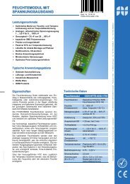
Figure 6. MPX5100 Pressure Regulator<br />
1K<br />
The Pressure Select Circuitry allows the user to choose a<br />
desired pressure by creating a reference voltage. This<br />
reference voltage is equivalent to the sensor output when the<br />
desired pressure exists in the system. A comparison is made<br />
between the sensor output and the reference voltage. When<br />
the system pressure is below the selected pressure, the motor<br />
is turned on to increase the pressure. When the system<br />
pressure reaches the selected pressure, the motor/pump<br />
turns off. Hysteresis is used to set different trip voltages for<br />
turn–off and turn–on to allow for noise and pressure<br />
fluctuations.<br />
For particular applications that only require one fixed<br />
regulated pressure, the Pressure Select Circuitry can be<br />
reduced to a single voltage reference. Additionally, the Motor<br />
Drive Circuitry can be simplified depending on the application<br />
requirements and the motor to be used. Since a +5.0 Vdc<br />
supply to the sensor provides an output that is ideal for<br />
interfacing with an A/D converter, this comparison could<br />
easily be converted to a software function, allowing for a digital<br />
pressure select input as well as controlling a digital display.<br />
Q1<br />
1/4 MPM3002<br />
Q3<br />
1/4 MPM3002<br />
47<br />
R4<br />
R7 47<br />
4 Motorola Sensor Device Data<br />
R6<br />
24<br />
R2<br />
470<br />
Q2<br />
1/4 MPM3002<br />
MOTOR +<br />
MOTOR –<br />
Q4<br />
1/4 MPM3002