DEM Extraction from OR2A Stereo and ERDAS LPS - DigitalGlobe
DEM Extraction from OR2A Stereo and ERDAS LPS - DigitalGlobe
DEM Extraction from OR2A Stereo and ERDAS LPS - DigitalGlobe

Create successful ePaper yourself
Turn your PDF publications into a flip-book with our unique Google optimized e-Paper software.
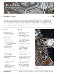
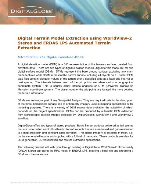
Digital Terrain Model <strong>Extraction</strong> using WorldView-2<br />
<strong>Stereo</strong> <strong>and</strong> <strong>ERDAS</strong> <strong>LPS</strong> Automated Terrain<br />
<strong>Extraction</strong><br />
Introduction: The Digital Elevation Model<br />
A digital elevation model (<strong>DEM</strong>) is a 3-D representation of the terrain’s surface, created <strong>from</strong><br />
elevation data. There are two types of digital elevation models, digital terrain model (DTM) <strong>and</strong><br />
digital surface model (DSM). DTMs represent the bare ground surface excluding any manmade<br />
features while DSMs represent the earth’s surface including all objects on it. Raster <strong>DEM</strong><br />
data files contain elevation values of the terrain over a specified area at a fixed grid interval or<br />
post spacing. The intervals between each of the grid points are referenced to a geographical<br />
coordinate system. This is usually either latitude-longitude or UTM (Universal Transverse<br />
Mercator) coordinate systems. The closer together the grid points are located, the more detailed<br />
the terrain information.<br />
<strong>DEM</strong>s are an integral part of any Geospatial Analysis. They are required both for the description<br />
of the three dimensional surface <strong>and</strong> to orthorectify imagery used in mapping applications or for<br />
modeling purposes. There is a variety of <strong>DEM</strong> source data available, the suitability of which<br />
depends on the project specifications. <strong>DEM</strong>s can be produced by automatic <strong>DEM</strong> extraction<br />
<strong>from</strong> stereoscopic satellite images collected by <strong>DigitalGlobe</strong>’s WorldView-1 <strong>and</strong> WorldView-2<br />
satellites.<br />
<strong>DigitalGlobe</strong> offers two types of stereo products; Basic <strong>Stereo</strong> products delivered as full scenes<br />
that are uncorrected <strong>and</strong> Ortho-Ready <strong>Stereo</strong> Products that are area-based <strong>and</strong> geo-referenced<br />
to a map projection <strong>and</strong> constant base elevation. The stereo imagery is collected in-track, e.g.<br />
on the same satellite pass <strong>and</strong> supplied with a full set of metadata. These products are ideal for<br />
<strong>DEM</strong> generation, 3D visualization <strong>and</strong> feature extraction applications.<br />
The following tutorial will walk you through loading a <strong>DigitalGlobe</strong> WorldView-2 Ortho-Ready<br />
(<strong>OR2A</strong>) <strong>Stereo</strong> pair using the RPC model in <strong>ERDAS</strong> <strong>LPS</strong>, creating a block file <strong>and</strong> extracting a<br />
<strong>DEM</strong> <strong>from</strong> the stereo pair.
Creating an <strong>LPS</strong> Block File<br />
1. To get started, open an instance of <strong>LPS</strong> <strong>from</strong> your Program files or <strong>from</strong> your start menu.<br />
Fig.1. Start <strong>LPS</strong> <strong>from</strong> Start Menu in Windows 7<br />
The <strong>LPS</strong> Project Manager window will open.<br />
2. From here you want to select File > New. You will be prompted to create a new <strong>LPS</strong><br />
block file.
Fig.2. Create New Block File<br />
3. Navigate to a drive where there is sufficient room (storage size) <strong>and</strong> in the File name<br />
window type the name of the block file. In this example we type the name mine site.<br />
Click OK when done.<br />
You will now be prompted to set up the Model. A Model Setup window will appear. Because we<br />
are using WorldView-2 stereo we have the option to use RPCs provided with the imagery. In<br />
this example we will use the supplied RPCs delivered with an <strong>OR2A</strong> <strong>Stereo</strong> product.
4. From the first dropdown select Rational Function. From the second dropdown select<br />
WorldView RPC. Click OK.<br />
Fig.3. Model Setup<br />
5. Next, the Block Property Setup menu will open. Here you can select a coordinate system<br />
for the block file. To do so select the Set… button <strong>and</strong> choose <strong>from</strong> a list of supplied<br />
coordinate system for both the horizontal <strong>and</strong> vertical. For this example we’ll use the<br />
default Projection: Geographic with the Datum of WGS84 <strong>and</strong> we’ll use the Vertical<br />
Spheroid <strong>and</strong> Datum default of WGS84. Once you have selected the coordinate System<br />
click the OK button.
Fig.4. Block Property Setup: Reference Coordinate System<br />
Load <strong>Stereo</strong> Pair<br />
6. Now you will load your stereo image pair. To do so, click on the Add Frame to the list<br />
button in the <strong>LPS</strong> Project Manager menu. Navigate to the folder that contains your<br />
stereo imagery. Select the left image first. In this case we are using WorldView-2<br />
Multispectral pairs. The left image will be the first image in the list. Select this image <strong>and</strong><br />
click OK (see Fig.5.)
Fig.5. Select first Image of <strong>Stereo</strong> Pair<br />
Once selected you will see the image loaded into the section below the view that has Row#,<br />
ImageID, Description, Image Name, Active, Pyramid, Int, etc….<br />
7. Repeat the steps of Adding frames to the list but this time select the Right image of the<br />
pair. This will load the right image. Click OK when done.
Assign Rational Polynomial Coefficient<br />
Now that the imagery is loaded you will see in the section that states Image Name that the<br />
active layers have Pyramids (green boxes) <strong>and</strong> is Online (green Boxes) but does not have the<br />
Interior <strong>and</strong> Exterior Orientations yet (in Red). Nor does it have DTM or Ortho. For this tutorial<br />
we will assign the Interior <strong>and</strong> Exterior Orientations using the RPC file provided with the <strong>OR2A</strong><br />
<strong>Stereo</strong> pair. We will also extract the DTM (later in the tutorial). But first we will assign the RPC<br />
orientation to the model.<br />
8. To do so click on under the Int. in the red box next to the first image in the pair. See<br />
Fig.6<br />
Fig.6. WorldView RPC Frame Editor Window
The WorldView RPC Frame Editor Window will appear. The image will automatically populate in<br />
the Image File Name (See Fig.6). The RPC Coefficients file will also automatically populate if<br />
the RPB file (File containing RPC information) is in the same folder as the imagery. (Fig.6).<br />
Elevation (meters) information is pulled <strong>from</strong> the RPB file <strong>and</strong> populated here. In this example<br />
we’ll select the defaults. And Click OK. Repeat the process (page 6 <strong>and</strong> 7) for assigning the<br />
RPC model to the second image (right image in pair) in the list by clicking on the red box next to<br />
the second image in the Int column.<br />
Now that the RPC model has been applied we can now add relative tie points to our model.<br />
TIE POINT PROCESS<br />
9. The process that we’ll use is the Automatic Tie Point . Click on this button to begin<br />
Auto Tie Point.<br />
Fig.7. Auto Tie Point
Once Auto Tie Point is complete an Auto Tie Summary will appear.<br />
Fig.8. Auto Tie Summary<br />
10. This window will provide a glimpse of how many tie points where collected <strong>and</strong> the<br />
success of the operation. Click Close when complete.<br />
<strong>DEM</strong> <strong>Extraction</strong><br />
11. Next, we’ll extract our <strong>DEM</strong>. In the <strong>LPS</strong> Project Manager toolbar select the DTM<br />
<strong>Extraction</strong> button. This will open the Start DTM <strong>Extraction</strong> window
Fig.9. Start DTM <strong>Extraction</strong><br />
12. From the dropdown window in Fig.9.you have the option to select Classic ATE. This is<br />
the process we’ll use for this example. Leave the “Always use DTM <strong>Extraction</strong> method.”<br />
Check box empty <strong>and</strong> click OK.<br />
A DTM <strong>Extraction</strong> window will appear<br />
Fig.10. DTM <strong>Extraction</strong> Window
13. In the output type there are a few choices you can select <strong>from</strong> including: 3D shape,<br />
ASCII, <strong>DEM</strong>, Socet Set TIN, LTF, <strong>and</strong> Terramodel TIN. For this example we’ll use <strong>DEM</strong>.<br />
14. Leave Background Value as Default. For Output Form: select Individual Files. If you<br />
choose the Individual DTM Files option, the DTMs extracted <strong>from</strong> each image pair have<br />
a separate output file. Give the DTM an output Name in the Output Prefix window.<br />
Navigate to a directory where you want this file to reside. It will have an .img prefix.<br />
15. For Cell Size You may specify a grid distance in the X <strong>and</strong> Y direction which is used<br />
to extract a DTM posting. In this example we’ll select double the GSD of WorldView-2<br />
MS of 4.00 meters. This defaults to 4.01 meters. Meters will be the units used.<br />
16. Use the Adaptive ATE. This is an advanced algorithm that extracts the elevation<br />
information <strong>from</strong> an image. The Adaptive ATE process asks you for specific information<br />
about the images so that the Adaptive ATE algorithm can take that information <strong>and</strong> fine<br />
tune the extraction process. The Adaptive ATE process takes longer to complete than<br />
the traditional ATE.<br />
17. Use the default for Stop at Pyramid <strong>and</strong> the default for Set the range <strong>from</strong>. The Set the<br />
Range From setting defaults to the global <strong>DEM</strong> file. If the block file does not have a<br />
Cartesian coordinate system <strong>and</strong> you want to use a different <strong>DEM</strong> for the minimum <strong>and</strong><br />
maximum Z values, then use the st<strong>and</strong>ard file selector to select a different <strong>DEM</strong>. If the<br />
block file has a Cartesian coordinate system, this field is not active; enter the elevation<br />
values in the Z Search Range fields.<br />
18. Finally we’ll give it a <strong>DEM</strong> accuracy of 5.00 meters, which is the vertical accuracy of<br />
WorldView-2.<br />
19. Once ready <strong>and</strong> all your parameters are set click Run<br />
The <strong>DEM</strong>.img file will be created in the directory that you provided in the Output Prefix window<br />
(Fig.10).<br />
Once the <strong>DEM</strong> has been created you can load the <strong>DEM</strong> in an IMAGINE viewer to view.
20. Open IMAGINE <strong>from</strong> your start menu.<br />
21. Click on File > Open >Raster Layer <strong>and</strong> Navigate to the directory with you <strong>DEM</strong>.img file<br />
Fig. 11. Load <strong>and</strong> View <strong>DEM</strong> in IMAGINE<br />
For more information on <strong>DEM</strong> extraction techniques in <strong>ERDAS</strong> <strong>LPS</strong> go to<br />
http://erdas.com/service/support/<strong>ERDAS</strong>Support.aspx<br />
For more technical information on <strong>DigitalGlobe</strong> Products <strong>and</strong> Services please visit<br />
http://www.digitalglobe.com/resources<br />
Additional Documents <strong>and</strong> Imagery Product Samples may be downloaded <strong>from</strong> here.