Cutting cylinder oil costs without a break in service - Wärtsilä
Cutting cylinder oil costs without a break in service - Wärtsilä
Cutting cylinder oil costs without a break in service - Wärtsilä

Create successful ePaper yourself
Turn your PDF publications into a flip-book with our unique Google optimized e-Paper software.
Photo: Nordcapital<br />
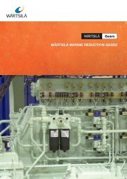
Pressure<br />
sensor<br />
Shut-off<br />
valve for<br />
lubricat<strong>in</strong>g <strong>oil</strong><br />
Cyl<strong>in</strong>der<br />
<strong>oil</strong> <strong>in</strong>let<br />
To system <strong>oil</strong><br />
dra<strong>in</strong> tank<br />
Relief valve<br />
for servo <strong>oil</strong><br />
Shut-off valve<br />
for servo <strong>oil</strong><br />
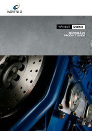
Fig. 3 – The RPLS lubricat<strong>in</strong>g module with lubricator connections and<br />
associated electronics for eight lubricators.<br />
WÄRTSILÄ TECHNICAL JOURNAL 02.2007<br />
Cyl<strong>in</strong>der <strong>oil</strong><br />
outlet to<br />
lubricators<br />
Vent<strong>in</strong>g plug for<br />
<strong>cyl<strong>in</strong>der</strong> <strong>oil</strong><br />
Vent<strong>in</strong>g plug<br />
for servo <strong>oil</strong><br />
4/2-way<br />
solenoid valve<br />
Diaphragm<br />
accumulator<br />
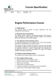
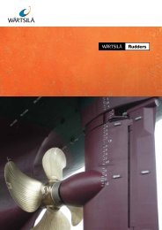
Fig. 4 – One of the n<strong>in</strong>e conta<strong>in</strong>er ships managed by E.R. Schiffahrt, which have<br />
been completely retrofitted with the Pulse Lubricat<strong>in</strong>g System. The ships are<br />
powered by <strong>Wärtsilä</strong> RTA96C low-speed diesel eng<strong>in</strong>es.<br />
shut-off valve. For RT-flex eng<strong>in</strong>es, servo<br />
<strong>oil</strong> is drawn from the eng<strong>in</strong>e servo <strong>oil</strong><br />
system through a pressure reduc<strong>in</strong>g valve<br />
by which the <strong>oil</strong> pressure is reduced from<br />
200 bar to 50 bar. The reduced pressure<br />
is monitored by pressure transmitters<br />
directly connected to the alarm system; the<br />
pipes are SOLAS compliant. The reduced<br />
pressure can be adjusted and its level is<br />
shown on an analogue pressure gauge.<br />
The lubricat<strong>in</strong>g module for each<br />
<strong>cyl<strong>in</strong>der</strong> consists of a dosage pump, a<br />
4/2-way solenoid valve, monitor<strong>in</strong>g<br />
electronics, pressure sensor, and diaphragm<br />
accumulator on a base plate. The timed<br />
lubricat<strong>in</strong>g module feeds a predefi ned<br />
metered quantity of <strong>cyl<strong>in</strong>der</strong> <strong>oil</strong> at high<br />
speed to the lubricators at the precise<br />
tim<strong>in</strong>g ascerta<strong>in</strong>ed by the eng<strong>in</strong>e control<br />
system. Part of the control <strong>oil</strong> fl ow from<br />
the servo <strong>oil</strong> l<strong>in</strong>e is routed to the 4/2-way<br />
solenoid valve. At the same time, the loaddependent<br />
<strong>cyl<strong>in</strong>der</strong> lubricat<strong>in</strong>g <strong>oil</strong> needs<br />
of the respective <strong>cyl<strong>in</strong>der</strong>s are ascerta<strong>in</strong>ed<br />
by the eng<strong>in</strong>e control system, which sends<br />
a correspond<strong>in</strong>g signal to the monitor<strong>in</strong>g<br />
electronics of the lubricat<strong>in</strong>g module. The<br />
ALM-20 (Advanced Lubricat<strong>in</strong>g Module)<br />
checks that the dosage pump is work<strong>in</strong>g<br />
correctly. The ALM-20 communicates<br />
with the master control unit through a<br />
redundant bus system, sends the signal to<br />
the 4/2-way solenoid valve, and processes<br />
the data from the pressure transmitter.<br />
The redesigned lubricator delivers the<br />
<strong>cyl<strong>in</strong>der</strong> <strong>oil</strong> radially as compact <strong>oil</strong> pulse<br />
feeds exactly <strong>in</strong>to the piston r<strong>in</strong>g package,<br />
from where it is equally distributed around<br />
the circumference of the <strong>cyl<strong>in</strong>der</strong> l<strong>in</strong>er.<br />
The lubricators (up to eight) are arranged<br />
around the l<strong>in</strong>er <strong>in</strong> one row to ensure an<br />
excellent distribution of the <strong>cyl<strong>in</strong>der</strong> <strong>oil</strong> on<br />
the <strong>cyl<strong>in</strong>der</strong> l<strong>in</strong>er. The vertical distribution<br />
is governed by the lubricat<strong>in</strong>g <strong>oil</strong> <strong>in</strong>jection<br />
tim<strong>in</strong>g as a function of the crank angle.<br />
A generously dimensioned 40micron<br />
<strong>cyl<strong>in</strong>der</strong> lubricat<strong>in</strong>g <strong>oil</strong> fi lter is<br />
arranged before the lubricat<strong>in</strong>g modules.<br />
It effectively removes any particles of<br />
dirt, thereby ensur<strong>in</strong>g reliable operation<br />
of the lubricat<strong>in</strong>g modules. A 12 litre<br />
buffer tank is provided with a scaled<br />
sight glass that enables <strong>cyl<strong>in</strong>der</strong> <strong>oil</strong><br />
consumption measurements of up to<br />
five litres. The buffer tank also allows<br />
the filter to be changed while the eng<strong>in</strong>e<br />
is runn<strong>in</strong>g. When the filter is dirty,<br />
the <strong>in</strong>tegrated sensor gives a signal on<br />
the excessive differential pressure. p<br />
<strong>in</strong>detail 53