User Guide Heat • Vent • Light - IXL
User Guide Heat • Vent • Light - IXL
User Guide Heat • Vent • Light - IXL

You also want an ePaper? Increase the reach of your titles
YUMPU automatically turns print PDFs into web optimized ePapers that Google loves.
®<br />
Tastic<br />
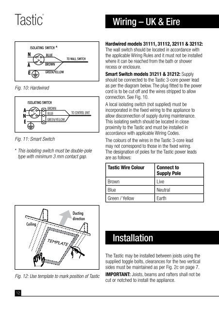
Fig. 10: Hardwired<br />
Fig. 11: Smart Switch<br />
* This isolating switch must be double-pole<br />
type with minimum 3 mm contact gap.<br />
Fig. 12: Use template to mark position of Tastic<br />
12<br />
Wiring – UK & Eire<br />
Hardwired models 31111, 31112, 32111 & 32112:<br />
The wall switch should be located in accordance with<br />
the applicable Wiring Rules and it must not be installed<br />
where it can be reached from the bath or shower<br />
recess or enclosure.<br />
Smart Switch models 31211 & 31212: Supply<br />
should be connected to the Tastic 3-core power lead<br />
as per the diagram below. The plug fitted to the power<br />
cord is to be cut off and the wires stripped to allow<br />
connection. See Fig. 10.<br />
A local isolating switch (not supplied) must be<br />
incorporated in the fixed wiring to the appliance to<br />
allow disconnection of supply during maintenance.<br />
This isolating switch should be located in close<br />
proximity to the Tastic and must be installed in<br />
accordance with applicable Wiring Codes.<br />
The colours of the wires in the Tastic 3-core lead<br />
may not correspond to those in the fixed wiring.<br />
The designation of poles for the Tastic power leads<br />
are as follows:<br />
Tastic Wire Colour Connect to<br />
Supply Pole<br />
Brown Live<br />
Blue Neutral<br />
Green / Yellow Earth<br />
Installation<br />
The Tastic may be installed between joists using the<br />
supplied toggle bolts, clearances for the two vertical<br />
sides must be maintained as per Fig. 2c on page 7.<br />
IMPORTANT: Joists, beams and rafters shall not be<br />
cut or notched to install the appliance.