User Guide Heat • Vent • Light - IXL
User Guide Heat • Vent • Light - IXL
User Guide Heat • Vent • Light - IXL

You also want an ePaper? Increase the reach of your titles
YUMPU automatically turns print PDFs into web optimized ePapers that Google loves.
®<br />
Tastic<br />
Fig. 20<br />
Fig. 21<br />
Fig. 22<br />
Fig. 24<br />
1 2<br />
6 G screws x 2<br />
Smart Switch<br />
LIGHT<br />
HEAT<br />
FAN<br />
ALLOFF<br />
Fig. 23<br />
3<br />
Installation<br />
layer on the tubular heat lamp is on the upper side<br />
of the lamp, ie lamp is pointing downwards.<br />
5. Clip the downlight mounts into the fascia.<br />
6. Fit the glass sheets to the heat lamp reflector<br />
bodies Fig. 20.<br />
7. Ensure that the dip switches in the hand set are<br />
correctly set for your local ventilation requirements<br />
Fig. 26-27 (pages 16-17).<br />
8. Turn on the power at the isolating switch and<br />
check operation of the Tastic.<br />
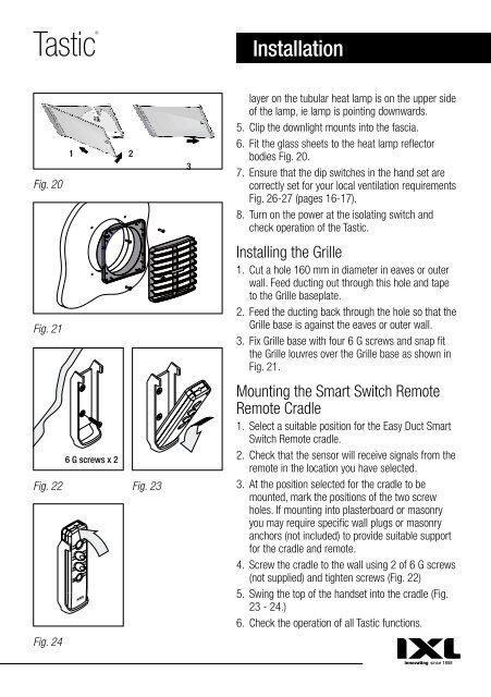
Installing the Grille<br />
1. Cut a hole 160 mm in diameter in eaves or outer<br />
wall. Feed ducting out through this hole and tape<br />
to the Grille baseplate.<br />
2. Feed the ducting back through the hole so that the<br />
Grille base is against the eaves or outer wall.<br />
3. Fix Grille base with four 6 G screws and snap fit<br />
the Grille louvres over the Grille base as shown in<br />
Fig. 21.<br />
Mounting the Smart Switch Remote<br />
Remote Cradle<br />
1. Select a suitable position for the Easy Duct Smart<br />
Switch Remote cradle.<br />
2. Check that the sensor will receive signals from the<br />
remote in the location you have selected.<br />
3. At the position selected for the cradle to be<br />
mounted, mark the positions of the two screw<br />
holes. If mounting into plasterboard or masonry<br />
you may require specific wall plugs or masonry<br />
anchors (not included) to provide suitable support<br />
for the cradle and remote.<br />
4. Screw the cradle to the wall using 2 of 6 G screws<br />
(not supplied) and tighten screws (Fig. 22)<br />
5. Swing the top of the handset into the cradle (Fig.<br />
23 - 24.)<br />
6. Check the operation of all Tastic functions.<br />
Smart Switch<br />
LIGHT<br />
HEAT<br />
FAN<br />
ALLOFF<br />
Smart Switch<br />
LIGHT<br />
HEAT<br />
FAN<br />
ALLOFF