Q35 Automatic Vent Damper System Product Bulletin - ShanControls
Q35 Automatic Vent Damper System Product Bulletin - ShanControls
Q35 Automatic Vent Damper System Product Bulletin - ShanControls

You also want an ePaper? Increase the reach of your titles
YUMPU automatically turns print PDFs into web optimized ePapers that Google loves.
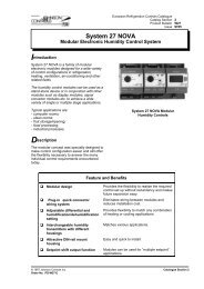
<strong>Q35</strong> <strong>Automatic</strong> <strong>Vent</strong> <strong>Damper</strong> <strong>System</strong><br />
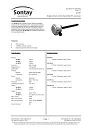
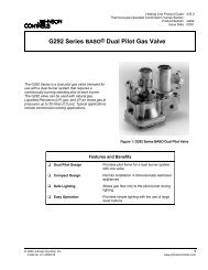
The <strong>Q35</strong> energy saving, high-efficiency, automatic vent<br />
damper system retains heat that is normally wasted<br />
through the open flue when the appliance is not firing.<br />
The <strong>Q35</strong> consists of a Y15 damper, M35 actuator, and<br />
Y84 wiring harness. The damper section is available in<br />
sizes from 102 mm (4 in.) through 305 mm (12 in.)<br />
nominal duct diameter.<br />
❑ Stainless Steel Duct, Blade,<br />
and Skirt Construction<br />
❑ Redundant End Position<br />
Switches<br />
❑ Position Indicator and LED<br />
(Light-Emitting Diode)<br />
Features and Benefits<br />
Heating Line <strong>Product</strong> Guide 435.0<br />
<strong>Vent</strong>/Flue <strong>Damper</strong>s Section<br />
<strong>Product</strong> <strong>Bulletin</strong> <strong>Q35</strong><br />
Issue Date 1098<br />
Figure 1: <strong>Q35</strong> <strong>Automatic</strong> <strong>Vent</strong> <strong>Damper</strong><br />
Provides a durable, resilient to harsh<br />
environments, positive sealing (minimizing flue<br />
byproducts) system<br />
Allows precise blade positioning for unrestricted<br />
byproducts of combustion flow<br />
Provides a visible indication of blade position and<br />
appliance power<br />
© 1998 Johnson Controls, Inc. 1<br />
Code No. LIT-4350750 www.johnsoncontrols.com
Application<br />
The <strong>Q35</strong> damper system can be used with boilers,<br />
furnaces, and other gas-fired appliances equipped with<br />
a vent connection 305 mm (12 in.) diameter or less.<br />
Models are available for standing pilot or electronic<br />
ignition systems.<br />
Note: In standing pilot applications, a stack<br />
assembly model with a vent hole must be<br />
used (see the Ordering Information section).<br />
The Y84 wiring harness is used to connect the M35<br />
actuator to the appliance. The Y84 electrically<br />
interlocks the damper system to the appliance.<br />
Unplugging either end results in a system shutdown.<br />
In addition, the Y84 incorporates a circuit that blows<br />
a special fuse found in most electronic ignition<br />
controls. This is designed to prevent system<br />
operation if a bypass plug, supplied with the ignition<br />
control, is later used in place of a damper.<br />
The damper assembly must be used only in<br />
conjunction with redundant gas valves (main burner<br />
gas must pass through both valve seats). The <strong>Q35</strong><br />
must not be used with valves that can be manually<br />
opened.<br />
Operation<br />
The damper actuator opens and closes the damper<br />
blade upon demand of the system thermostat.<br />
The damper must be in the open position before the<br />
main burner circuit is energized. It will remain open<br />
while the main burner is operating.<br />
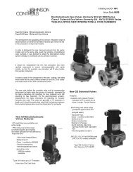
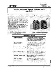
A damper blade position indicator and a green light<br />
are visible on the front label of the actuator. The light<br />
signifies that power from the thermostat has opened<br />
the damper and that power is available to the<br />
appliance for main burner ignition. See Figure 2.<br />
2 <strong>Q35</strong> <strong>Automatic</strong> <strong>Vent</strong> <strong>Damper</strong> <strong>System</strong> <strong>Product</strong> <strong>Bulletin</strong><br />
AUTOMATIC DAMPER<br />
M35BA-1<br />
INPUT 24V 50/60 Hz<br />
OPERATING CURRENT: 0.2A<br />
CONTACT RATING: 2A STEADY<br />
5A INRUSH<br />
POSITION INDICATOR<br />
OPEN ROTATION<br />
CLOSED<br />
INDICATOR LIGHT<br />
"ON" - DAMPER OPEN<br />
Figure 2: Label Diagnostic Indicators<br />
Sequence of Operation<br />
The <strong>Q35</strong> operates in the following manner:<br />
1. The damper is in the closed position.<br />
2. The thermostat contacts close on a call for heat.<br />
3. The M35 actuator rotates the damper blade to<br />
the open position. Power is available for main<br />
burner ignition (green light is on).<br />
4. The system thermostat reaches setpoint and<br />
contacts open.<br />
5. The burner circuit is de-energized and the M35<br />
closes the damper.<br />
6. The system is now ready for the next heating<br />
cycle.
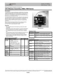
Manual Opening<br />
If an actuator failure occurs and a replacement is not<br />
readily available, the appliance may temporarily be<br />
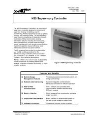
returned to service. After moving a wire lead inside<br />
the actuator to disable the motor (see Figure 3), the<br />
flat shaft is easily turned with a wrench or pliers to<br />
the open position, providing burner operation on<br />
each thermostat cycle. Condensed instructions are<br />
printed on the circuit board.<br />
Remove wire<br />
from here.<br />
Place it here.<br />
Figure 3: Moving Motor Lead Wire<br />
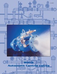
Figure 4: Manual Rotation<br />
After turning the shaft, the damper will remain in the<br />
open position and supply power to the ignition circuit<br />
on demand of the system thermostat. However, the<br />
vent damper will not provide energy savings until a<br />
replacement actuator is obtained from the original<br />
equipment manufacturer or an authorized<br />
Johnson Controls distributor.<br />
<strong>Q35</strong> <strong>Automatic</strong> <strong>Vent</strong> <strong>Damper</strong> <strong>System</strong> <strong>Product</strong> <strong>Bulletin</strong> 3
Dimensions<br />
M35AA-1<br />
Table 1: <strong>Q35</strong> Dimensions<br />
4 <strong>Q35</strong> <strong>Automatic</strong> <strong>Vent</strong> <strong>Damper</strong> <strong>System</strong> <strong>Product</strong> <strong>Bulletin</strong><br />
38<br />
1.50<br />
81<br />
3.19<br />
Figure 5: Dimensions, mm (in.)<br />
Duct Size/“A” Inlet Opening “B” Outlet Outside Diameter “C” Height<br />
84<br />
3.30<br />
Standing Pilot <strong>System</strong><br />
84<br />
3.30<br />
30<br />
1.20<br />
138<br />
5.42<br />
30<br />
1.20<br />
138<br />
5.42<br />
Electronic Ignition <strong>System</strong><br />
mm in. mm in. mm in.<br />
102 4.00 100 3.95 152 6.00<br />
127 5.00 126 4.95 152 6.00<br />
152 6.00 151 5.95 152 6.00<br />
178 7.00 177 6.95 171 6.75<br />
203 8.00 202 7.95 197 7.75<br />
230 9.00 228 8.95 249 9.75<br />
255 10.00 254 9.95 249 9.75<br />
305 12.00 306 11.95 300 11.75
Ordering Information<br />
1st<br />
Letter<br />
<strong>Damper</strong><br />
Operator<br />
Wiring<br />
Harness<br />
Q 3 5 _ _ - _ _<br />
Customer-specific Requirements<br />
2nd<br />
Letter Stack Assembly Stack Description<br />
C M35BA Y84 A Y15AE or *Y15ME 102 mm (4 in.)<br />
without vent hole<br />
F M35BC Y84 B Y15MF or *Y15MF 102 mm (4 in.)<br />
with vent hole<br />
H M35BC None C Y15NE or *Y15NE 127 mm (5 in.)<br />
without vent hole<br />
D M35BB Y84 D Y15NF or *Y15NF 127 mm (5 in.)<br />
with vent hole<br />
E Y15PE or *Y15PE 152 mm (6 in.)<br />
without vent hole<br />
F Y15PF or *Y15PF 152 mm (6 in.)<br />
with vent hole<br />
G Y15QE or *Y15OE 178 mm (7 in.)<br />
without vent hole<br />
H Y15QF or *Y15OF 178 mm (7 in.)<br />
with vent hole<br />
J Y15RE or *Y15RE 203 mm (8 in.)<br />
without vent hole<br />
K Y15RF or *Y15RF 203 mm (8 in.)<br />
with vent hole<br />
L Y15SE or *Y15SG 230 mm (9 in.)<br />
without vent hole<br />
M Y15SF or *Y15SH 230 mm (9 in.)<br />
with vent hole<br />
N Y15TE or *Y15TG 255 mm (10 in.)<br />
without vent hole<br />
P Y15TF or *Y15TH 255 mm (10 in.)<br />
with vent hole<br />
Q Y15HG or *Y15UG 305 mm (12 in.)<br />
without vent hole<br />
R Y15HH or *Y15UH 305 mm (12 in.)<br />
with vent hole<br />
*Indicates a short duct damper.<br />
The presence of a particular construction in this information does not guarantee its availability. Consult Johnson Controls<br />
for available constructions.<br />
Figure 6: Ordering Matrix<br />
<strong>Q35</strong> <strong>Automatic</strong> <strong>Vent</strong> <strong>Damper</strong> <strong>System</strong> <strong>Product</strong> <strong>Bulletin</strong> 5
6 <strong>Q35</strong> <strong>Automatic</strong> <strong>Vent</strong> <strong>Damper</strong> <strong>System</strong> <strong>Product</strong> <strong>Bulletin</strong><br />
Notes
Notes<br />
<strong>Q35</strong> <strong>Automatic</strong> <strong>Vent</strong> <strong>Damper</strong> <strong>System</strong> <strong>Product</strong> <strong>Bulletin</strong> 7
Specifications<br />
<strong>Product</strong> <strong>Q35</strong> <strong>Automatic</strong> <strong>Vent</strong> <strong>Damper</strong><br />
Voltage 24 VAC, 50/60 Hz<br />
Available<br />
Sizes<br />
8 <strong>Q35</strong> <strong>Automatic</strong> <strong>Vent</strong> <strong>Damper</strong> <strong>System</strong> <strong>Product</strong> <strong>Bulletin</strong><br />
D o (Effectiveness)<br />
Nominal Diameter Intermittent Standing<br />
mm in. Ignition Pilot<br />
Material Stack/Blade: 430 Stainless Steel<br />
Cover/Case: Galvanized Steel<br />
Maximum<br />
Operating<br />
Temperature<br />
Y84<br />
Termination<br />
Agency<br />
Listing<br />
Specification<br />
Standards<br />
102 4.00 0.006 0.065<br />
127 5.00 0.004 0.041<br />
152 6.00 0.002 0.028<br />
178 7.00 0.002 0.021<br />
203 8.00 0.002 0.017<br />
230 9.00 0.069 0.081<br />
255 10.00 0.070 0.079<br />
305 12.00 0.085 0.092<br />
Actuator: 66°C (150°F)<br />
Stack: 274°C (525°F)<br />
Actuator End: Board Edge Connection (Standard)<br />
Molex Receptacle (Optional)<br />
Appliance End: Molex Plug (Standard)<br />
Bare or Terminals (Optional)<br />
<strong>Q35</strong> components Y15 and M35<br />
IAS (AGA, CGA) Certificate Number C2154004<br />
ANSI Standard Z21.66<br />
CAN1-2.28-M81<br />
The performance specifications are nominal and conform to acceptable industry standards. For application at conditions beyond these<br />
specifications, consult the local Johnson Controls office. Johnson Controls, Inc. shall not be liable for damages resulting from<br />
misapplication or misuse of its products.<br />
Refer to the <strong>Q35</strong> Series Technical <strong>Bulletin</strong> (LIT-121340 and LIT-121515) for necessary information on the installation, use, and servicing of this product.<br />
Controls Group www.johnsoncontrols.com<br />
507 E. Michigan Street FAN 435.0<br />
P.O. Box 423 Heating Line <strong>Product</strong> Guide<br />
Milwaukee, WI 53201 Printed in U.S.A.