Heat Loss from Electrical and Control Equipment in - Kansas State ...
Heat Loss from Electrical and Control Equipment in - Kansas State ...
Heat Loss from Electrical and Control Equipment in - Kansas State ...

Create successful ePaper yourself
Turn your PDF publications into a flip-book with our unique Google optimized e-Paper software.
<strong>Heat</strong> <strong>Loss</strong> <strong>from</strong> <strong>Electrical</strong> <strong>and</strong> <strong>Control</strong><br />
<strong>Equipment</strong> <strong>in</strong> Industrial Plants:<br />
Part !-Methods <strong>and</strong> Scope<br />
Warren N. White, Ph.D. Anil Pahwa, Ph.D.<br />
ABSTRACT<br />
Accurate estimates of heat lost by power equipment facil-<br />
itate proper siz<strong>in</strong>g of cool<strong>in</strong>g <strong>and</strong> ventilation equipment<br />
required by build<strong>in</strong>gs <strong>and</strong> <strong>in</strong>dustrial plants. Information on<br />
heat loss is available <strong>in</strong> papers published <strong>in</strong> the 1970s <strong>and</strong><br />
1980s, but some of the <strong>in</strong>formationprovided <strong>in</strong> thesepapers is<br />
dated <strong>and</strong>, <strong>in</strong> some cases, <strong>in</strong>cludes overly conservative<br />
assumptions. The ma<strong>in</strong> focus of this paper is to describe an<br />
efJbrt to provide updated <strong>in</strong>formation on heat losses by various<br />
electric power devices. The <strong>in</strong>formation was gathered <strong>from</strong><br />
equipment manufacturers <strong>and</strong> relevant st<strong>and</strong>ards associated<br />
with this equipment. Laboratory tests or mathematical simu-<br />
lations were done to determ<strong>in</strong>e heat loss for equipment with<br />
<strong>in</strong>suficient <strong>in</strong>formation <strong>and</strong> to verzb published data. A calo-<br />
rimeter was constructed for the test<strong>in</strong>g of equipment. The<br />
construction <strong>and</strong> calibration of the calorimeter are described.<br />
Testprocedures used <strong>in</strong> acquir<strong>in</strong>g loss data are described. For<br />
each equipment item <strong>in</strong> the scope of the project, a description<br />
is provided as to where <strong>and</strong> how the loss data were obta<strong>in</strong>ed.<br />
A summary of areas for future <strong>in</strong>vestigation is discussed.<br />
INTRODUCTION<br />
In order to size cool<strong>in</strong>g <strong>and</strong> ventilat<strong>in</strong>g equipment, the<br />
HVAC design eng<strong>in</strong>eer must be able to estimate with certa<strong>in</strong>ty<br />
the amount of energy added <strong>from</strong> various heat sources <strong>and</strong> lost<br />
through various heat s<strong>in</strong>ks located <strong>in</strong> a room. <strong>Heat</strong> could be<br />
added <strong>from</strong> several sources such as the presence of many<br />
people <strong>in</strong> a classroom or office, solar radiation through<br />
w<strong>in</strong>dows, <strong>and</strong> room light<strong>in</strong>g. A s<strong>in</strong>k could consist of outside<br />
doors <strong>and</strong> w<strong>in</strong>dows <strong>in</strong> w<strong>in</strong>ter or a basement floor or wall that<br />
rema<strong>in</strong>s at an essentially constant temperature throughout the<br />
year. By closely estimat<strong>in</strong>g the heat ga<strong>in</strong> <strong>in</strong> a room or space,<br />
Chris Cruz<br />
the HVAC equipment will not be undersized with <strong>in</strong>sufficient<br />
capacity or oversized with costly unutilized excess capability.<br />
Build<strong>in</strong>g <strong>and</strong> <strong>in</strong>dustrial plants make use of electrical<br />
power for many uses such as light<strong>in</strong>g, driv<strong>in</strong>g motorized<br />
devices, HVAC, <strong>and</strong> energy distribution throughout the struc-<br />
ture. All of this electrical equipment contributes to the total<br />
heat load. Estimat<strong>in</strong>g the total amount of rejected heat is a<br />
necessary part of siz<strong>in</strong>g the ventilat<strong>in</strong>g <strong>and</strong> cool<strong>in</strong>g equipment<br />
required for the build<strong>in</strong>g.<br />
The primary source of <strong>in</strong>formation available to the design<br />
eng<strong>in</strong>eer for estimat<strong>in</strong>g the electrical equipment rejected heat<br />
is the paper by Rub<strong>in</strong> (1979). In this often used document, the<br />
rejected heat values for transformers, power distribution<br />
equipment, motors, switchgear, <strong>and</strong> power cables, to name a<br />
few, were presented <strong>in</strong> tables for a range of equipment sizes<br />
common to <strong>in</strong>door equipment. The data presented by Rub<strong>in</strong><br />
were obta<strong>in</strong>ed <strong>from</strong> the paper presented by Hickok (1 978) <strong>and</strong><br />
<strong>from</strong> other unspecified manufacturers. Hickok states that the<br />
data he presented were obta<strong>in</strong>ed exclusively <strong>from</strong> one manu-<br />
facturer. At no po<strong>in</strong>t <strong>in</strong> either Hickok's paper or <strong>in</strong> Rub<strong>in</strong>'s<br />
paper is there a discussion of measurement procedure or<br />
measurement uncerta<strong>in</strong>ty. Rub<strong>in</strong>'s motivation for publish<strong>in</strong>g<br />
the data was to aid the HVAC design eng<strong>in</strong>eer. Hickok's moti-<br />
vation <strong>in</strong> his paper was to aid the factory eng<strong>in</strong>eer <strong>in</strong> identify-<br />
<strong>in</strong>g plant locations where efficiency could be improved.<br />
Hickok's motivation is easy to appreciate s<strong>in</strong>ce the energy<br />
crisis provided by two oil embargoes made <strong>in</strong>creas<strong>in</strong>g effi-<br />
ciency of exist<strong>in</strong>g plants, build<strong>in</strong>gs, <strong>and</strong> factories the first<br />
choice <strong>in</strong> reduc<strong>in</strong>g the costs of production. McDonald <strong>and</strong><br />
Hickok (1 985) later issued an update of Hickok's paper (1 978)<br />
with much of the same data.<br />
Warren N. White is an associate professor <strong>and</strong> Chris Cruz is a graduate student <strong>in</strong> the Mechanical <strong>and</strong> Nuclear Eng<strong>in</strong>eer<strong>in</strong>g Department, <strong>and</strong><br />
Anil Pahwa is a professor <strong>in</strong> the <strong>Electrical</strong> <strong>and</strong> Computer Eng<strong>in</strong>eer<strong>in</strong>g Department, <strong>Kansas</strong> <strong>State</strong> University, Manhattan, Kans.<br />
02004 ASHRAE.
The <strong>in</strong>formation provided by these papers is dated. S<strong>in</strong>ce<br />
the oil embargoes of the 1970s, many electrical equipment<br />
manufacturers have <strong>in</strong>creased the efficiency of their products.<br />
At the same time, advances <strong>in</strong> power electronics <strong>and</strong> computer<br />
control have made much of the technology reflected <strong>in</strong> the<br />
1970 equipment obsolete. Another change that has occurred<br />
s<strong>in</strong>ce Rub<strong>in</strong> published his work is that the manufactur<strong>in</strong>g stan-<br />
dards that apply to the various items ofpower equipment have<br />
been re-issued <strong>and</strong> updated several times. These st<strong>and</strong>ards<br />
could provide details for measur<strong>in</strong>g the power loss <strong>in</strong> the<br />
equipment where, perhaps, orig<strong>in</strong>ally none existed. Also, the<br />
st<strong>and</strong>ards might specify a maximum level of uncerta<strong>in</strong>ty for<br />
perform<strong>in</strong>g the measurements, <strong>and</strong> any data reported by a<br />
manufacturer claim<strong>in</strong>g to follow the st<strong>and</strong>ard could be deemed<br />
reliable. Thus, there is a need to update the 20-year-old <strong>in</strong>for-<br />
mation orig<strong>in</strong>ally presented by Rub<strong>in</strong>. A recent addition to the<br />
published <strong>in</strong>formation regard<strong>in</strong>g motor heat ga<strong>in</strong>s is conta<strong>in</strong>ed<br />
<strong>in</strong> Chapter 29 of the 2001 ASHRAE H<strong>and</strong>book-Fzmdamen-<br />
taIs that provides a table of "<strong>Heat</strong> Ga<strong>in</strong>s <strong>from</strong> Typical Electric<br />
Motors" for fractional horsepower AC motors up to 250 horse-<br />
power three phase motors.<br />
The purpose of this work is to probide a methodology for<br />
estimat<strong>in</strong>g the rejected heat of specific electrical equipment by<br />
means similar to Rub<strong>in</strong> <strong>and</strong> to account for updated data,<br />
current test<strong>in</strong>g st<strong>and</strong>ards, level of use, <strong>and</strong> more than one<br />
power equipment manufacturer. This paper describes the work<br />
done <strong>in</strong> reach<strong>in</strong>g the stated work purpose. The first part of this<br />
paper describes the methods of data collection <strong>and</strong> equipment<br />
test<strong>in</strong>g together with areas for future work. The second part<br />
Electric motors<br />
<strong>Equipment</strong><br />
Medium-voltage switchgear (breakers,<br />
heaters, <strong>and</strong> auxiliary com~artments)<br />
summarizes the data collection <strong>and</strong> test results <strong>and</strong> provides a<br />
comparison between the recently obta<strong>in</strong>ed <strong>in</strong>formation <strong>and</strong><br />
that available <strong>from</strong> the cited earlier work.<br />
PROJECT SCOPE<br />
Table 1. <strong>Equipment</strong> Investigated<br />
The scope ofthe equipment <strong>in</strong>vestigated is listed <strong>in</strong> Table<br />
1. Installed electrical equipment is normally not operated at<br />
100% of full load on a cont<strong>in</strong>uous basis s<strong>in</strong>ce no buffer would<br />
exist to accommodate any unanticipated <strong>in</strong>crease <strong>in</strong> power<br />
dem<strong>and</strong>. As a result, it was necessary to be able to determ<strong>in</strong>e<br />
equipment heat loss at partial loads. In addition to heat loss at<br />
fractional loads, it was necessary to account for equipment<br />
diversity, i.e., the equipment be<strong>in</strong>g used only dur<strong>in</strong>g a portion<br />
of the time.<br />
Early <strong>in</strong> the project, a dist<strong>in</strong>ction between types of heat<br />
transfer <strong>and</strong> operat<strong>in</strong>g conditions was drawn. The equipment<br />
rate of heat losses determ<strong>in</strong>ed <strong>in</strong> this work represents constant<br />
values <strong>from</strong> steady operation. The device reject<strong>in</strong>g heat is<br />
assumed to have reached thermal equilibrium with the<br />
surround<strong>in</strong>gs, <strong>and</strong> no thermal transient process is tak<strong>in</strong>g place.<br />
Thus, all heat loss occumng <strong>in</strong> a device is additional heat<br />
added to the surround<strong>in</strong>gs. The manner <strong>in</strong> which the heat trans-<br />
fer takes place is not of concern. <strong>Heat</strong> convection to the<br />
surround<strong>in</strong>gs <strong>and</strong> conduction to surround<strong>in</strong>g structures are not<br />
hard to appreciate as viable transfer mechanisms. Any thermal<br />
radiation is assumed to be absorbed by the surround<strong>in</strong>g struc-<br />
tures (perhaps after several absorptions <strong>and</strong> re-emissions), <strong>and</strong><br />
Size Range<br />
10-4000 h~ (reg. <strong>and</strong> high efficiency)<br />
5 kV, 7.2 kV, <strong>and</strong> 13.8 kV with 1200,2000, <strong>and</strong> 3000 amp breakers 1<br />
I<br />
Unit substation components (<strong>in</strong>clud<strong>in</strong>g breakers, heaters, bus losses, 800, 1600,2000, 3200, <strong>and</strong> 4000 amp frame sizes<br />
<strong>and</strong> auxiliary compartments)<br />
i Transformers 300-2500 kVA <strong>and</strong> 120/208/600 V units below 300 kVA 1<br />
1 Reactors 1 St<strong>and</strong>ard sizes i<br />
Panelboards<br />
Cable <strong>and</strong> cable trays<br />
- -<br />
St<strong>and</strong>ard sizes for 120, 125, <strong>and</strong> 600 V<br />
0.6, 5, <strong>and</strong> 15 kV of widths 12 <strong>in</strong>.-30 <strong>in</strong>.<br />
I<br />
I Battery chargers 1 100 to 600 amp 1<br />
Inverters 20, 30, 50,75, <strong>and</strong> 100 kVA-s<strong>in</strong>gle phase<br />
1 DC switchgear 1 125 VDC for 100 to 1500 amp 1<br />
I<br />
1 Manual transfer switches 0.6 kV for 150.260.400,600,800, <strong>and</strong> 1000 amp I<br />
Motor control centers (comb<strong>in</strong>ation starters, breakers, auxiliary relay St<strong>and</strong>ard NEMA sizes<br />
compartments, bus losses, <strong>and</strong> space heaters)<br />
1 Variable (adjustable) speed drives 25 to 500 hp-three phase<br />
ASHRAE Transactions: Symposia 843<br />
-
the eventual manifestation of the radiant energy is an <strong>in</strong>crease<br />
<strong>in</strong> heat load. It should be po<strong>in</strong>ted out that the radiant <strong>and</strong><br />
convective split of heat loss is an important part of the cool<strong>in</strong>g<br />
load determ<strong>in</strong>ation <strong>and</strong> should not be ignored. The data<br />
provided by this work are the total heat loss. How to split the<br />
loss will be a function of the device, enclosure, load, <strong>and</strong> appli-<br />
cation.<br />
METHODS OF DATA COLLECTION<br />
The <strong>in</strong>itial stages of the project consisted of a literature<br />
review, review of manufactur<strong>in</strong>g st<strong>and</strong>ards for heat loss test<strong>in</strong>g<br />
procedures, e-mail<strong>in</strong>g requests for equipment loss data to the<br />
electrical equipment manufacturers, <strong>and</strong> exam<strong>in</strong><strong>in</strong>g manufac-<br />
turers' Web sites <strong>and</strong> catalogs for heat loss <strong>in</strong>formation. The<br />
results of each of these <strong>in</strong>quiries are described <strong>in</strong> the foilow<strong>in</strong>g<br />
paragraphs. Based on the results of this <strong>in</strong>itial survey, a test<br />
plan was developed.<br />
Surveys<br />
Outside of the works cited earlier by Hickock, Rub<strong>in</strong>, <strong>and</strong><br />
McDonald, there are no other reported <strong>in</strong>vestigations <strong>in</strong>volv-<br />
<strong>in</strong>g equipment heat loss. One notable <strong>and</strong> extremely useful<br />
reference uncovered dur<strong>in</strong>g this search is the text by Anders<br />
(1997), which develops an extensive model of heat loss <strong>and</strong><br />
temperature rise of cable bundles. The model presented by<br />
Anders is an extension of the orig<strong>in</strong>al work of Neher <strong>and</strong><br />
McGrath (1957). An updated cable model is presented by<br />
Harshe <strong>and</strong> Black (1994).<br />
In parallel to the effort of review<strong>in</strong>g literature, the manu-<br />
factur<strong>in</strong>g st<strong>and</strong>ards for the equipment under study relevant to<br />
heat loss were identified. The identification process began by<br />
creat<strong>in</strong>g a list of manufactur<strong>in</strong>g st<strong>and</strong>ards relevant to the type<br />
of equipment. This was first attempted by search<strong>in</strong>g manufac-<br />
turers' Web sites for the specific st<strong>and</strong>ards that were followed<br />
<strong>in</strong> the equipment production. An improved method of accu-<br />
mulat<strong>in</strong>g this <strong>in</strong>formation was through the Web sites of orga-<br />
nizations such as the National Electric Manufacturers<br />
Association (NEMA) <strong>and</strong> the Institute of <strong>Electrical</strong> <strong>and</strong> Elec-<br />
tronics Eng<strong>in</strong>eers (IEEE). In addition to the organizations just<br />
mentioned, st<strong>and</strong>ards <strong>from</strong> the American National St<strong>and</strong>ards<br />
Institute (ANSI) <strong>and</strong> the Undedters Laboratory (UL) were<br />
also reviewed. The list of relevant st<strong>and</strong>ards was ref<strong>in</strong>ed by<br />
exclud<strong>in</strong>g those st<strong>and</strong>ards that did not address equipment heat<br />
loss or efficiency. St<strong>and</strong>ards were found that covered heat loss<br />
measurement procedures for only the equipment categories of<br />
transformers, series reactors, battery chargers, <strong>and</strong> electric<br />
motors. Many of the st<strong>and</strong>ards reviewed were concerned with<br />
temperature rise s<strong>in</strong>ce high temperatures promote <strong>in</strong>sulation<br />
degradation, yet only few treat heat loss or efficiency. The rele-<br />
vant transformer st<strong>and</strong>ards are IEEE Std. (257.12.90, IEEE<br />
C57.12.91, <strong>and</strong> NEMA TP 1 <strong>and</strong> NEMA TP 2. For electric<br />
motors, the essential st<strong>and</strong>ards are IEEE Std. 112, IEEE Std.<br />
113, IEEE Std. 11 5, <strong>and</strong> NEMA MG 1. St<strong>and</strong>ard IEEE C57.16<br />
is the document detail<strong>in</strong>g procedures for measur<strong>in</strong>g series<br />
reactor heat loss, while NEMA PE 5 treats battery chargers. It<br />
was concluded that transformer <strong>and</strong> electric motor manufac-<br />
turers followed the st<strong>and</strong>ards cited <strong>from</strong> statements made on<br />
various manufacturers' Web sites. However, no series reactor<br />
manufacturer was found to follow IEEE C57.16. The fact that<br />
st<strong>and</strong>ards cover<strong>in</strong>g heat loss measurements are followed by<br />
manufacturers is significant s<strong>in</strong>ce published loss data are<br />
subject to the uncerta<strong>in</strong>ty levels specified by the st<strong>and</strong>ards;<br />
thus, the quality of the published <strong>in</strong>formation can be easily<br />
<strong>in</strong>ferred. <strong>Heat</strong> loss <strong>in</strong>formation was found for battery chargers<br />
<strong>in</strong> the st<strong>and</strong>ard NEMA PE 5, cover<strong>in</strong>g utility type battery<br />
chargers; however, no manufacturer was found that claimed to<br />
follow this relevant st<strong>and</strong>ard that specifies how battery charger<br />
efficiency is to be determ<strong>in</strong>ed.<br />
A side benefit of the st<strong>and</strong>ards search provided <strong>in</strong>forma-<br />
tion regard<strong>in</strong>g the <strong>in</strong>fluence of ambient temperature on equip-<br />
ment heat losses. Accord<strong>in</strong>g to the cited st<strong>and</strong>ards,<br />
environmental temperature has only a small <strong>in</strong>fluence on<br />
transformer, motor, or series reactor heat losses.<br />
In this work, one very important source of <strong>in</strong>formation is<br />
equipment manufacturers. Manufacturers of a particular<br />
equipment item were located through a search of the NEMA<br />
Web site. This search provided the start<strong>in</strong>g po<strong>in</strong>t for any<br />
contact with equipment manufacturers s<strong>in</strong>ce postal <strong>and</strong> e-mail<br />
addresses were available.<br />
Contact through e-mail was made to the companies<br />
<strong>in</strong>cluded on the manufacturer lists to <strong>in</strong>quire about dissipated<br />
heat <strong>from</strong> their products. S<strong>in</strong>ce a contact was be<strong>in</strong>g made with<br />
equipment manufacturers, <strong>in</strong>formation not only relevant to the<br />
classification was sought but also <strong>in</strong>formation useful to other<br />
parts of the study. For each type ofpower equipment <strong>in</strong>volved<br />
<strong>in</strong> the survey, a contact letter was written that expla<strong>in</strong>ed the<br />
nature of the project <strong>and</strong> requested <strong>in</strong>formation relevant to this<br />
study. The requested <strong>in</strong>formation consists of the name <strong>and</strong><br />
number of the st<strong>and</strong>ards followed <strong>in</strong> determ<strong>in</strong><strong>in</strong>g the loss<br />
numbers or the procedures used to determ<strong>in</strong>e the losses <strong>in</strong> the<br />
case where no loss determ<strong>in</strong>ation procedures are specified <strong>in</strong><br />
the st<strong>and</strong>ards. Also, the manufacturer was requested to supply<br />
loss numbers for its products or to specify the Web pages <strong>and</strong>l<br />
or public company documents where loss figures are<br />
presented. This step was not done for every piece of equipment<br />
under study, e.g., cables, s<strong>in</strong>ce it was not expected that power<br />
losses would vary <strong>from</strong> manufacturer to manufacturer <strong>and</strong><br />
excellent mathematical cable loss models are available.<br />
Each of the equipment types was documented regard<strong>in</strong>g<br />
applicable st<strong>and</strong>ards, loss measurement methods, availability<br />
of loss data, <strong>and</strong> results of the manufacturer survey. From the<br />
accumulated data, the equipment was classified <strong>in</strong>to one of<br />
three categories. The first category consisted of those products<br />
for which the st<strong>and</strong>ards require specific, well-def<strong>in</strong>ed tests for<br />
loss determ<strong>in</strong>ation <strong>and</strong> report<strong>in</strong>g <strong>in</strong> addition to the availability<br />
of published loss <strong>in</strong>formation. The third category <strong>in</strong>cludes<br />
equipment for which there was no st<strong>and</strong>ard either requir<strong>in</strong>g or<br />
describ<strong>in</strong>g any heat loss tests <strong>and</strong> for which no heat loss data<br />
could be found. The second category <strong>in</strong>cluded all equipment<br />
satisfy<strong>in</strong>g neither of the first nor third category descriptions.<br />
844 ASHRAE Transactions: Symposia
Items <strong>in</strong> the second category represent a wide range of differ-<br />
ent situations or conditions. The best description for this cate-<br />
gory is that <strong>in</strong>formation was available on equipment heat<br />
losses, but the measurement quality was unknown. The first<br />
category <strong>in</strong>cluded transformers <strong>and</strong> motors. The devices <strong>in</strong> the<br />
second category were reactors, medium-voltage switchgear,<br />
circuit breakers, motor control centers, <strong>in</strong>verters, battery<br />
chargers, adjustable-speed drives, plus cables <strong>and</strong> cable trays.<br />
The rema<strong>in</strong>der of the power equipment constituted the third<br />
category that <strong>in</strong>cludes transfer switches, DC switchgear, <strong>and</strong><br />
panelboards.<br />
From the assessment determ<strong>in</strong>ed <strong>in</strong> the previous activities,<br />
a test plan was devised to provide as much of the <strong>in</strong>formation<br />
as possible for cover<strong>in</strong>g the equipment heat losses for the items<br />
listed <strong>in</strong> Table 1. In the case of the first category equipment, the<br />
<strong>in</strong>formation was gathered <strong>from</strong> manufacturers' Web sites, cata-<br />
logs, survey <strong>in</strong>formation, <strong>and</strong> personal contacts. For the equip-<br />
ment <strong>in</strong> the second <strong>and</strong> third categories, the test plan <strong>in</strong>volved<br />
experimental procedures for build<strong>in</strong>g <strong>and</strong>lor verify<strong>in</strong>g the<br />
<strong>in</strong>formation necessary to complete this study. Both the steps of<br />
the test plan <strong>and</strong> the necessary experimental apparatus will be<br />
described for each of the required equipment items.<br />
Test Plan <strong>and</strong> Test Facility<br />
Ideally, the test<strong>in</strong>g phase of this work would consist of<br />
test<strong>in</strong>g a sufficient quantity of the equipment <strong>in</strong> the second <strong>and</strong><br />
third categories to provide the necessary <strong>in</strong>formation that<br />
would allow accurate heat loss predictions for heat load calcu-<br />
lations. The test<strong>in</strong>g phase had to provide the greatest amount<br />
of <strong>in</strong>formation given limited resources. The only way to deter-<br />
m<strong>in</strong>e heat loss <strong>in</strong>formation for equipment <strong>in</strong> the third category<br />
would be to purchase a sufficient quantity of equipment so that<br />
the ranges specified <strong>in</strong> Table 1 could be adequately covered.<br />
The large quantity of equipment to be purchased was neces-<br />
sitated by the lack of published heat loss <strong>in</strong>formation. The<br />
conclusion drawn about the third category equipment was that<br />
no test<strong>in</strong>g of this equipment would be undertaken. <strong>Loss</strong> <strong>in</strong>for-<br />
mation for the second category equipment could be located.<br />
The concern of this published loss <strong>in</strong>formation was its accu-<br />
racy, so the aim of test<strong>in</strong>g the second category equipment was<br />
to check the published loss data. The loss data check<strong>in</strong>g could<br />
be accomplished by test<strong>in</strong>g a reasonable sample of equipment<br />
consist<strong>in</strong>g of different sizes. Some of the second category<br />
equipment <strong>in</strong>volved large <strong>and</strong> expensive components such as<br />
medium-voltage switchgear, motor control centers, or unit<br />
substations. These three equipment examples have much <strong>in</strong><br />
common besides price <strong>and</strong> size <strong>and</strong> consist of many of the<br />
same components, such as bus bars, breakers, <strong>and</strong> space heat-<br />
ers. The strategy developed for determ<strong>in</strong><strong>in</strong>g the heat loss of the<br />
three mentioned items was to use a menu approach through a<br />
spreadsheet. The spreadsheet would allow the eng<strong>in</strong>eer to pick<br />
<strong>and</strong> choose the components mak<strong>in</strong>g up the equipment <strong>in</strong> order<br />
to calculate the total heat loss. The crucial <strong>in</strong>formation <strong>in</strong> this<br />
spreadsheet calculation is the component heat loss. It was then<br />
only necessary to check the heat loss data of as many of the<br />
components as economically feasible. F<strong>in</strong>ally, it was not<br />
possible to test all ofthe second category equipment due to the<br />
expense necessary to purchase a representative sample of<br />
products. In those cases where test<strong>in</strong>g was not done, the gath-<br />
ered catalog <strong>and</strong> Web site loss data were reported with the<br />
proviso that no provision for verification of the data accuracy<br />
was possible.<br />
The goal of the test<strong>in</strong>g was to determ<strong>in</strong>e the heat losses of<br />
the equipment under various loads with<strong>in</strong> different environmen-<br />
tal temperatures. To facilitate the test<strong>in</strong>g work, an environmental<br />
chamber/calorimeter was constructed out of 4-<strong>in</strong>.-thick Styro-<br />
foam. The wall thickness was achieved by glu<strong>in</strong>g two 2-<strong>in</strong>.-thick<br />
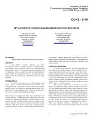
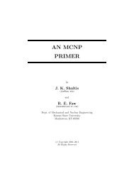
sheets of blue construction <strong>in</strong>sulation. Figure 1 illustrates the<br />
salient po<strong>in</strong>ts of the environmental chamber. The <strong>in</strong>terior dimen-<br />
sions of the chamber were 5 ft <strong>in</strong> height, 2.5 ft <strong>in</strong> depth, <strong>and</strong> 3.5<br />
ft <strong>in</strong> width. Access to the chamber was accomplished by remov-<br />
<strong>in</strong>g one wall. Room temperature air was supplied to the chamber<br />
through two variable-speed squirrel cage fans mounted at the<br />
base of the chamber. The two fans operated at the same speed.<br />
The volume flow rate of the exit air was metered by a vane<br />
anemometer mounted <strong>in</strong> a horizontal exit tube attached to the top<br />
of the chamber. An idi-ared source <strong>and</strong> detector were mounted<br />
on either side of the anemometer blades. The frequency of the<br />
detector diode signal was then a measure of the volume flow rate.<br />
The detector frequency could be determ<strong>in</strong>ed us<strong>in</strong>g an oscillo-<br />
scope, or could be determ<strong>in</strong>ed by the data acquisition system by<br />
pass<strong>in</strong>g the detector signal through a frequency to voltage<br />
converter chip. The calibration of the anemometer was accom-<br />
plished by mount<strong>in</strong>g the chamber exhaust tube <strong>and</strong> anemometer<br />
on the end of a w<strong>in</strong>d tunnel. The temperature of the <strong>in</strong>let air <strong>and</strong><br />
outlet air was measured by type-T thermocouples with shielded,<br />
twisted leads to limit signalnoise. The <strong>in</strong>terior temperature ofthe<br />
chamber was measured by four of the same thermocouples. The<br />
thermocouples were calibrated by means of a variable-tempera-<br />
ture bath. The data acquisition system supplied cold junction<br />
compensation. Electric power was supplied to equipment placed<br />
<strong>in</strong> the chamber by three-phase l<strong>in</strong>es pass<strong>in</strong>g through the chamber<br />
wall. A s<strong>in</strong>gle-phase l<strong>in</strong>e was also passed through the chamber<br />
wall to supply power to an array of lightbulbs placed <strong>in</strong> the<br />
bottom of the chamber. The purpose of the lightbulbs was to<br />
supply heat <strong>in</strong> order to ma<strong>in</strong>ta<strong>in</strong> the chamber temperature at a<br />
specific value <strong>and</strong> to help calibrate the chamber. The <strong>in</strong>let ducts,<br />
outlet duct, power cable entry <strong>and</strong> exit, <strong>and</strong> thermocouple wire<br />
entry were sealed with silicone. The removable wall was held <strong>in</strong><br />
place while the chamber operated by wooden boards <strong>and</strong> pipe<br />
clamps. The edges of the removable wall were sealed with duct<br />
tape. All permanent seams between sides of the chamber were<br />
glued, sealed with silicone, <strong>and</strong> covered with alum<strong>in</strong>um tape.<br />
Withthe exception of the <strong>in</strong>let <strong>and</strong> outlet ducts, the chamber<br />
could be made airtight.<br />
The equipment be<strong>in</strong>g tested <strong>in</strong> this study can be grouped<br />
<strong>in</strong>to roughly two classes. The first class consists of items that<br />
are connected <strong>in</strong> series with the electrical supply l<strong>in</strong>es. Some<br />
examples of the series devices are circuit breakers, comb<strong>in</strong>a-<br />
tion motor starters, <strong>and</strong> series reactors. The second class of<br />
ASHRAE Transactions: Symposia 845
Turbrne<br />
~ + i e r m o Flowmeter c o u p ~ e<br />
[ Fan ~ontrd~~er Am!ient<br />
Figure 1 Illustration of test chamber.<br />
Insulated Box<br />
Test Article<br />
equipment consisted of those devices that are connected <strong>from</strong><br />
the supply l<strong>in</strong>e to the ground. The best example of this equip-<br />
ment class is the adjustable-speed drive. The tested series<br />
devices dissipated as much as a few kilowatts that could be<br />
measured with a wattmeter.<br />
The chamber was used to provide a constant environmen-<br />
tal temperature while the heat dissipation test was be<strong>in</strong>g<br />
conducted. In order to provide a constant temperature envi-<br />
ronment, a control system was programmed <strong>in</strong>to the data<br />
acquisition system. The heat<strong>in</strong>g sources <strong>in</strong>side the chamber<br />
consisted of the device be<strong>in</strong>g tested <strong>and</strong> those lightbulbs that<br />
are turned on. The temperature <strong>in</strong>side the chamber is<br />
measured, <strong>and</strong> if the actual temperature is higher or lower than<br />
the desired setpo<strong>in</strong>t temperature, the airflow rate through the<br />
chamber is raised or lowered, respectively. The variable-speed<br />
drives on the fan motors were driven by a signal <strong>from</strong> the data<br />
acquisition system. The chamber temperature controller was a<br />
proportional-<strong>in</strong>tegral type that provides an easy way to ma<strong>in</strong>-<br />
ta<strong>in</strong> the actual temperature close to the desired temperature.<br />
In order to test adjustable-speed drives, the drives had to<br />
be loaded at the proper horsepower rat<strong>in</strong>g. The largest adjust-<br />
able-speed drive on h<strong>and</strong> for test<strong>in</strong>g was rated at 60 hp. The<br />
power l<strong>in</strong>es supply<strong>in</strong>g the drive were passed through the<br />
chamber wall. The l<strong>in</strong>es attached to the load were also passed<br />
through the chamber wall. The load for the drive consisted of<br />
resistive heat<strong>in</strong>g elements mounted <strong>in</strong>side two 55-gallon<br />
drums. This resistive load is <strong>in</strong>cluded <strong>in</strong> the illustration of<br />
Figure 1. Power <strong>from</strong> the heat<strong>in</strong>g elements was dissipated by<br />
runn<strong>in</strong>g tap water through the drum to a floor dra<strong>in</strong> <strong>in</strong> the lab.<br />
nermocouples ' \<br />
(if needed)<br />
Each drum was capable of dissipat<strong>in</strong>g 30 hp. One drum<br />
consisted of <strong>in</strong>dustrial heat<strong>in</strong>g elements, while the other drum<br />
was constructed out of 220-volt residential hot water heat<strong>in</strong>g<br />
elements. In order to determ<strong>in</strong>e the dissipated heat, the airflow<br />
rate was measured along with the <strong>in</strong>let <strong>and</strong> outlet air temper-<br />
atures. The dissipated heat was determ<strong>in</strong>ed by<br />
where<br />
Q = rate of rejected or dissipated heat,<br />
p = density of air,<br />
v = air volume flow rate,<br />
cp = specific heat of air,<br />
To,, = outlet air temperature, <strong>and</strong><br />
7;, = <strong>in</strong>let air temperature.<br />
The control system was used to change the airflow by<br />
vary<strong>in</strong>g the fan speed so that the chamber rema<strong>in</strong>ed at the<br />
desired environmental temperature.<br />
In test<strong>in</strong>g the series connected devices, it wasnecessary to<br />
create large electrical currents, which at times consisted of<br />
several thous<strong>and</strong> amperes, to load the test devices at the rated<br />
level. Series devices are designed so that the voltage drop<br />
across the device is small <strong>in</strong> order to limit power dissipation;<br />
thus, the large electrical currents could be delivered at a very<br />
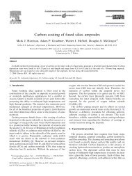
low voltage. Figure 2 illustrates the means by which large<br />
currents were created. The creation of the large current was<br />
846 ASHRAE Transactions: Symposia
Variable<br />
Autotransformer<br />
Current r-----1<br />
5:2000<br />
S<strong>in</strong>gle Phase Apparatus for Test<strong>in</strong>g<br />
<strong>Loss</strong>es <strong>in</strong> Series Connected Devices<br />
Environmental<br />
Chamber<br />
Outlet 4-<br />
Current I ,<br />
t<br />
/ Environmental<br />
i Chamber<br />
P P P<br />
H H H<br />
A A A<br />
S S S b ~ e s t<br />
/ Article<br />
A B C<br />
t<br />
I<br />
1 l2OVAC<br />
S<strong>in</strong>gle<br />
Figure 2 S<strong>in</strong>gle-phase test setup for measur<strong>in</strong>g the power Figure 3 S<strong>in</strong>gle-phase connections for test<strong>in</strong>g some series<br />
loss of series devices. devices.<br />
accomplished by a s<strong>in</strong>gle-phase current transformer<br />
connected <strong>in</strong> reverse. The turns ratio of the transformer was as<br />
high as 5:2000, which allowed a wide range of currents to be<br />
created. Figure 2 shows the s<strong>in</strong>gle-phase version of this appa-<br />
ratus that was used for the test<strong>in</strong>g of devices such as circuit<br />
breakers or motor starters. Figure 3 shows how the test setup<br />
is used for measur<strong>in</strong>g the power loss of some three-phase<br />
devices. Usually the power loss ofthese devices was relatively<br />
small so that the lightbulbs at the bottom of the environmental<br />
chamber were necessary to ma<strong>in</strong>ta<strong>in</strong> the desired setpo<strong>in</strong>t<br />
temperature <strong>in</strong>side the chamber. Theoretically, the heat loss<br />
<strong>from</strong> the series device could be used to heat the chamber <strong>and</strong><br />
to ma<strong>in</strong>ta<strong>in</strong> the setpo<strong>in</strong>t temperature. For these situations, the<br />
flow rate of the air through the chamber was very small, <strong>and</strong><br />
the speed controllers on the fans would overheat, try<strong>in</strong>g to<br />
drive the fans at a high-current low-speed configuration. The<br />
autotransformer used <strong>in</strong> this test setup was a three-phase<br />
device <strong>and</strong> could be used <strong>in</strong> creat<strong>in</strong>g a three-phase test setup,<br />
where each phase of the apparatus appeared similar to Figure<br />
2 with the exception that the two-wattmeter method was used<br />
for measur<strong>in</strong>g the three-phase power dissipation. The three-<br />
phase test apparatus was required when measur<strong>in</strong>g the power<br />
dissipation of series reactors s<strong>in</strong>ce it was necessary to ma<strong>in</strong>ta<strong>in</strong><br />
the proper phase relation between the magnetic fluxes <strong>in</strong> the<br />
reactor legs to ensure proper operation <strong>and</strong> typical power<br />
losses.<br />
The wattmeter <strong>in</strong> Figure 2 measures the power dissipated<br />
by the tested device, the current transformer, <strong>and</strong> the high<br />
current leads connected to the test article. In order to determ<strong>in</strong>e<br />
the power loss of the test article, the test article was removed<br />
<strong>from</strong> the circuit, <strong>and</strong> the high current leads were shorted<br />
together <strong>in</strong>side the sealed chamber with the environmental<br />
temperature set at the desired level. The autotransformer<br />
supply<strong>in</strong>g power to the test circuit was adjusted so that the<br />
required current flowed through the high current leads. The<br />
ASHRAE Transactions: Symposia<br />
power loss created by this configuration was measured by the<br />
wattmeter. The test article was then connected <strong>in</strong> the circuit,<br />
<strong>and</strong> the power dissipation was aga<strong>in</strong> measured under the same<br />
environmental conditions. The difference between the two<br />
read<strong>in</strong>gs was the power loss of the device be<strong>in</strong>g tested. Pa<strong>in</strong>s<br />
were taken to ensure that the difference between the two read-<br />
<strong>in</strong>gs was significant. The high current leads consisted of 210<br />
AWG weld<strong>in</strong>g cable. When very large currents were required,<br />
several weld<strong>in</strong>g cables were connected <strong>in</strong> parallel to limit the<br />
heat dissipated <strong>in</strong> the test circuit <strong>and</strong> to limit the voltage drop<br />
<strong>in</strong> the test circuit.<br />
The lightbulbs <strong>in</strong> the bottom of the environmental cham-<br />
ber served another extremely useful purpose besides the heat-<br />
<strong>in</strong>g of the chamber for some of the tests. The lights, which<br />
consisted of six 200-watt <strong>and</strong> two 150-watt bulbs, could be<br />
turned on <strong>and</strong> off separately. The s<strong>in</strong>gle-phase l<strong>in</strong>e supply<strong>in</strong>g<br />
the lights was connected to a wattmeter so that the power dissi-<br />
pated by the lights <strong>and</strong>, thus, added to the chamber environ-<br />
ment could be determ<strong>in</strong>ed. This known power <strong>in</strong>put allowed<br />
the chamber to be calibrated <strong>in</strong> terms of the use of Equation 1.<br />
Sett<strong>in</strong>g the lights to a specific power level <strong>and</strong> us<strong>in</strong>g Equation<br />
1 to calculate the measured power output after all thermal tran-<br />
sients <strong>in</strong> the chamber had expired allowed a calibration curve<br />
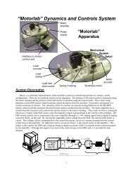
for the chamber to be developed. Figure 4 shows the calibra-<br />
tion curve for the chamber. The slope of the curve is very close<br />
to unity. The uncerta<strong>in</strong>ty of the measured heat loss was well<br />
with<strong>in</strong> the f 10% level established as the target uncerta<strong>in</strong>ty for<br />
loss measurements made <strong>in</strong> this work.<br />
It is worthwhile to po<strong>in</strong>t out a few miscellaneous details<br />
concern<strong>in</strong>g the test<strong>in</strong>g procedures. Support structures were<br />
created on which to mount the test articles. All articles tested<br />
were placed <strong>in</strong>side the environmental chamber with the excep-<br />
tion of the larger series reactors, which were too unwieldy to<br />
easily move <strong>and</strong> so heavy that they would have crushed the<br />
Styrofoam floor of the chamber. The test articles were
1600 -<br />
0 ,<br />
Thermal Chamber Calibration<br />
Measured Watts -Cum Fit<br />
0 200 400 600 800 1000 1200 1400 1600<br />
Figure 4 Thermal chamber calibration.<br />
mounted at approximately the center of the chamber, both<br />
horizontally <strong>and</strong> vertically. The thermocouples measur<strong>in</strong>g the<br />
chamber temperature were all placed close to the test article <strong>in</strong><br />
such a way as to surround the device be<strong>in</strong>g tested. The cham-<br />
ber temperature was determ<strong>in</strong>ed by averag<strong>in</strong>g the read<strong>in</strong>gs of<br />
the thermocouples placed close to the test article. The thermo-<br />
couples sens<strong>in</strong>g the <strong>in</strong>let <strong>and</strong> outlet air temperature were not<br />
<strong>in</strong>cluded <strong>in</strong> this average. All thermocouple read<strong>in</strong>gs were<br />
filtered with low pass filters to elim<strong>in</strong>ate noise. Values <strong>from</strong><br />
the evaluation of Equation 1 were passed through a low pass<br />
filter with exponential weight<strong>in</strong>g to elim<strong>in</strong>ate excessive fluc-<br />
tuations <strong>in</strong> read<strong>in</strong>gs. All filter<strong>in</strong>g of measurements was<br />
performed by the data acquisition system. Steps were taken to<br />
ensure that the uncerta<strong>in</strong>ty ofmeasured power loss was with<strong>in</strong><br />
*lo%.<br />
Summary of Data Sources<br />
For each of the equipment items placed <strong>in</strong> the first <strong>and</strong><br />
second categories, the data sources developed <strong>in</strong> this <strong>in</strong>vesti-<br />
gation will be described. Also the <strong>in</strong>fluence of ambient<br />
temperature on heat loss will also be described.<br />
Transformers. St<strong>and</strong>ards for the loss measurement of<br />
transformers exist <strong>and</strong> are observed by manufacturers. Catalog<br />
<strong>and</strong> Web site data for general purpose transformers<br />
constructed with either dry-type or <strong>in</strong>sulat<strong>in</strong>g liquid-<br />
immersed w<strong>in</strong>d<strong>in</strong>gs were found. From the relevant st<strong>and</strong>ards,<br />
it was learned that power losses were not a strong function of<br />
environmental temperature. The manufactur<strong>in</strong>g st<strong>and</strong>ards<br />
Input Watts<br />
specify the m<strong>in</strong>imum efficiency for distribution transformers<br />
as a function of voltage classification <strong>and</strong> <strong>in</strong>sulation. Power<br />
losses can be determ<strong>in</strong>ed based on these m<strong>in</strong>imum efficien-<br />
cies.<br />
Motors. The manufactur<strong>in</strong>g st<strong>and</strong>ards applicable to the<br />
measurement of motor power losses are observed by the motor<br />
manufacturers. Data were acquired <strong>from</strong> manufacturers' Web<br />
sites <strong>and</strong> catalogs for a wide variety of horsepower rat<strong>in</strong>gs <strong>and</strong><br />
frame types. For motor power rat<strong>in</strong>gs of 200 horsepower <strong>and</strong><br />
smaller, m<strong>in</strong>imum efficiencies for motors were legislated<br />
through the U.S. Energy Policy Act of 1992, provid<strong>in</strong>g a<br />
means-of estimat<strong>in</strong>g motor power losses <strong>in</strong> this range. For<br />
motors hav<strong>in</strong>g rat<strong>in</strong>gs of greater than 2000 horsepower, no<br />
published <strong>in</strong>formation was found. It was discovered that<br />
motors <strong>in</strong> this size range are custom built for which losses<br />
could vary accord<strong>in</strong>g to customer motor specification <strong>and</strong><br />
applications.<br />
Medium-Voltage Switchgear. Ow<strong>in</strong>g to the availability<br />
<strong>and</strong> expense of medium-voltage switchgear, no test<strong>in</strong>g was<br />
possible with<strong>in</strong> the scope of this project. While there are<br />
proprietary models <strong>and</strong> software packages used by manufac-<br />
turers for estimat<strong>in</strong>g the heat loss of these devices, the only<br />
devices uncovered <strong>in</strong> this effort were simplified models for<br />
determ<strong>in</strong><strong>in</strong>g rejected heat. Likewise, some manufacturers<br />
publish some general tables for predict<strong>in</strong>g the heat loss.<br />
Although this <strong>in</strong>formation was obta<strong>in</strong>ed <strong>from</strong> the latest<br />
versions of manufacturers' documents, some of the <strong>in</strong>forma-<br />
tion still matches data conta<strong>in</strong>ed <strong>in</strong> McDonald <strong>and</strong> Hickok<br />
848 ASHRAE Transactions: Symposia<br />
I
(1985). The menu approach mentioned <strong>in</strong> an earlier section<br />
was taken <strong>in</strong> predict<strong>in</strong>g the equipment heat losses. A spread-<br />
sheet was developed to estimate the heat losses for a given<br />
switchgear construction. Manufacturer data were found for<br />
each of the components listed <strong>in</strong> the menu. The collected<br />
manufacturer data were <strong>in</strong>cluded <strong>in</strong> this spreadsheet. The only<br />
test<strong>in</strong>g that was possible was of one medium-voltage breaker.<br />
The measured losses were on par with the collected manufac-<br />
turer data. No estimate of the quality of manufacturer <strong>in</strong>for-<br />
mation obta<strong>in</strong>ed can be made. The <strong>in</strong>fluence of ambient<br />
temperature on losses cannot be determ<strong>in</strong>ed. The enclos<strong>in</strong>g of<br />
switchgear components <strong>in</strong>side cab<strong>in</strong>ets is believed to <strong>in</strong>crease<br />
the losses of the components. The size of the <strong>in</strong>fluence of the<br />
enclosure on losses could not be determ<strong>in</strong>ed.<br />
Cables <strong>and</strong> Cable Trays. Analytical models for cable<br />
losses were used <strong>in</strong> estimat<strong>in</strong>g the dissipated heat. These<br />
models took <strong>in</strong>to account the number of cables, the cable tray<br />
width, <strong>and</strong> the ambient temperature. It was concluded that<br />
ambient temperature did not significantly <strong>in</strong>fluence losses.<br />
Tables of cable losses were developed by us<strong>in</strong>g the analytical<br />
models. No test<strong>in</strong>g of cables was carried out.<br />
Comb<strong>in</strong>ation Motor Starters. NEMA sizes of 0 through<br />
3 were tested <strong>in</strong> this work. The test results compared favorably<br />
to manufacturer published <strong>in</strong>formation. No test<strong>in</strong>g was<br />
performed on NEMA sizes 4 through 6. Manufacturer data<br />
were found for starter sizes 4 <strong>and</strong> 5. Environmental tempera-<br />
ture was found not to be a significant factor <strong>in</strong> starter losses.<br />
The starters of size 1 <strong>and</strong> larger were only tested <strong>in</strong> their enclo-<br />
sures s<strong>in</strong>ce the enclosure was an <strong>in</strong>tegral part of the starter.<br />
Published loss data were comparable to the tests of this study.<br />
Motor <strong>Control</strong> Centers. Manufacturer power bus loss<br />
data for motor control centers were found. No test<strong>in</strong>g ofpower<br />
bus losses was made. A spreadsheet was prepared us<strong>in</strong>g the<br />
bus loss data together with the comb<strong>in</strong>ation starter power<br />
losses for predict<strong>in</strong>g the losses <strong>from</strong> a motor control center.<br />
Inverters. Power <strong>in</strong>verters, which convert DC power to<br />
AC power, were not tested <strong>in</strong> this work. <strong>Heat</strong> loss <strong>in</strong>formation<br />
for this type of equipment was gathered <strong>from</strong> manufacturers'<br />
Web sites <strong>and</strong> catalogs. The reported <strong>in</strong>formation consisted of<br />
<strong>in</strong>verter efficiency as a function ofrated KVA. No claim of heat<br />
loss accuracy was made by the manufacturers present<strong>in</strong>g loss<br />
<strong>in</strong>formation. The <strong>in</strong>fluence of environmental temperature<br />
could not be determ<strong>in</strong>ed.<br />
Battery Chargers. Battery banks are used <strong>in</strong> emergency<br />
situations. Battery chargers are used to recharge the banks <strong>and</strong><br />
to ma<strong>in</strong>ta<strong>in</strong> the battery charge. Information <strong>from</strong> several<br />
manufacturers regard<strong>in</strong>g battery charger power loss <strong>and</strong> efi-<br />
ciency were located. No test<strong>in</strong>g of battery chargers was<br />
performed <strong>in</strong> this work. No claims of accuracy of the loss<br />
figures were made by the manufactures report<strong>in</strong>g power<br />
losses. Ambient temperature <strong>in</strong>fluence on losses could not be<br />
determ<strong>in</strong>ed.<br />
Low-Voltage Circuit Breakers. Low-voltage circuit<br />
breakers of 60, 100,250,800, <strong>and</strong> 1200 amp frame sizes were<br />
tested <strong>in</strong> this work. The breakers were tested <strong>in</strong> different<br />
ASHRAE Transactions: Symposia<br />
temperature environments <strong>and</strong> were tested both with <strong>and</strong> with-<br />
out enclosures. The environmental temperature did not play a<br />
significant factor <strong>in</strong> breaker power losses. The enclosure did<br />
play a significant role where it was seen that the power losses<br />
<strong>in</strong>creased by a factor of almost 1.5 <strong>in</strong> some of the breaker loss<br />
tests. The factor of 1.5 was chosen s<strong>in</strong>ce that bracketed all of<br />
the enclosure loss data. The reported loss <strong>in</strong>formation <strong>from</strong><br />
manufacturers for low-voltage breakers varied over a wide<br />
range. It was not clear if some of the reported data <strong>in</strong>volve<br />
enclosures or not. The assumption was made that the reported<br />
data for those breaker frames not tested did not <strong>in</strong>volve enclo-<br />
sures. Plots of the peak breaker loss as a function of frame size<br />
varied roughly <strong>in</strong> a l<strong>in</strong>ear fashion. These plots were used to<br />
predict the breaker losses for those frames not tested. The larg-<br />
est frame for which heat loss was reported by a manufacturer<br />
was 5000 amp.<br />
Unit Substations. Unit substations can be thought of as<br />
low-voltage switchgear. Information <strong>from</strong> the low-voltage<br />
breaker tests was used together with manufacturer component<br />
losses for current transformers, power buses, auxiliary<br />
compartments, control power transformers, <strong>and</strong> space heaters.<br />
In order to predict the unit substation losses, a spreadsheet was<br />
developed. No <strong>in</strong>formation on accuracy was available for the<br />
manufacturer reported component losses. Ow<strong>in</strong>g to the exces-<br />
sive costs, no unit substations were available for test<strong>in</strong>g <strong>in</strong> this<br />
<strong>in</strong>vestigation. The <strong>in</strong>fluence of ambient temperature on the<br />
losses of components not tested could not be determ<strong>in</strong>ed.<br />
Series Reactors. The series reactor is used for both limit-<br />
<strong>in</strong>g fault current <strong>and</strong> <strong>in</strong> filter<strong>in</strong>g <strong>in</strong>verter-produced noise on<br />
electric motor power feeds. <strong>Loss</strong> <strong>in</strong>formation <strong>from</strong> four differ-<br />
ent manufacturers was found. Reactors of sizes 4, 18,200, <strong>and</strong><br />
750 amps were tested. For the 200 <strong>and</strong> 750 amp sizes, two<br />
reactors <strong>from</strong> different manufacturers were tested. The test<br />
results compared favorably with the reported loss figures. It<br />
was observed that the absolute w<strong>in</strong>d<strong>in</strong>g temperature rise must<br />
be used to scale the losses so that the manufacturer reported<br />
losses would agree with the measured results. Accord<strong>in</strong>g to<br />
st<strong>and</strong>ards, the losses are reported as if the reactor conductors<br />
are at room temperature. Although st<strong>and</strong>ards exist for measur-<br />
<strong>in</strong>g reactor power losses, no manufacturer report<strong>in</strong>g loss <strong>in</strong>for-<br />
mation stated that these st<strong>and</strong>ards were observed <strong>in</strong> the test<strong>in</strong>g<br />
of their products. Environmental temperature was not a signif-<br />
icant <strong>in</strong>fluence on the reactor losses.<br />
Adjustable-Speed Drives. Adjustable-speed drives<br />
(ASD) are also known as variable-frequency drives (VFD).<br />
Drives of 25 <strong>and</strong> 60 hp sizes were tested <strong>in</strong> this work. Also,<br />
loss <strong>in</strong>formation <strong>from</strong> several manufacturers was found <strong>in</strong> this<br />
effort. The published loss <strong>in</strong>formation consisted of power loss<br />
as a function of drive rat<strong>in</strong>g <strong>in</strong> horsepower for the st<strong>and</strong>ard<br />
supply voltages of 230, 460, <strong>and</strong> 600 volts. So many loss<br />
values were available that it was possible to plot the loss as a<br />
function of rat<strong>in</strong>g for each of the supply voltage levels. A<br />
strik<strong>in</strong>g l<strong>in</strong>ear trend was apparent even though different<br />
manufacturers' data were on the same graph. The l<strong>in</strong>ear trends<br />
allowed curve fitt<strong>in</strong>g of the heat loss <strong>in</strong>formation as a function
of rat<strong>in</strong>g. The loss test results compared favorably with the<br />
manufacturer reported losses. S<strong>in</strong>ce the enclosure for the<br />
drives are an <strong>in</strong>tegral part of the device, no tests were<br />
performed without an enclosure. Ambient temperature did not<br />
present itself as a significant factor <strong>in</strong> the size of the heat<br />
losses. From published imformation, it appears that the drive<br />
losses vary as a l<strong>in</strong>ear function of drive current.<br />
CONCLUSIONS<br />
This document has described a systematic <strong>in</strong>vestigation<br />
<strong>in</strong>to the quantification of power loss <strong>from</strong> the various types of<br />
electrical equipment found <strong>in</strong> build<strong>in</strong>gs <strong>and</strong> <strong>in</strong>dustrial plants.<br />
The motivation for this study stems <strong>from</strong> the need of HVAC<br />
eng<strong>in</strong>eers to be able to accurately predict the equipment power<br />
loss <strong>in</strong> order to correctly size the necessary heat<strong>in</strong>g <strong>and</strong> cool-<br />
<strong>in</strong>g equipment for the structure. This is the first significant<br />
effort <strong>in</strong> this area <strong>in</strong> nearly 20 years. The power loss <strong>from</strong> many<br />
types of electrical equipment was determ<strong>in</strong>ed by a process<br />
consist<strong>in</strong>g of several steps. The first step <strong>in</strong>volved discover<strong>in</strong>g<br />
those equipment classes for which manufactur<strong>in</strong>g st<strong>and</strong>ards<br />
exist that detail how power losses are measured <strong>and</strong> are<br />
observed by manufacturers. <strong>Loss</strong> <strong>in</strong>formation published by<br />
those manufacturers who claimed to follow these st<strong>and</strong>ards<br />
was deemed credible <strong>and</strong> hav<strong>in</strong>g the same uncerta<strong>in</strong>ties as<br />
established by the manufactur<strong>in</strong>g st<strong>and</strong>ards. The second step<br />
<strong>in</strong> the <strong>in</strong>vestigation <strong>in</strong>volved creat<strong>in</strong>g <strong>and</strong> execut<strong>in</strong>g a test plan<br />
to verify the published loss data for those equipment classes<br />
for which loss measur<strong>in</strong>g st<strong>and</strong>ards do not exist or are not<br />
observed by manufacturers. The test<strong>in</strong>g was carried out to the<br />
extent possible. Of the equipment listed <strong>in</strong> the orig<strong>in</strong>al project<br />
scope, three equipment classes fell <strong>in</strong>to the category where<br />
there were no manufactur<strong>in</strong>g st<strong>and</strong>ards for measur<strong>in</strong>g losses<br />
<strong>and</strong> no published loss <strong>in</strong>formation could be found.<br />
In the <strong>in</strong>stances where tests on equipment items were<br />
made, several useful facts were uncovered. In several cases,<br />
the test results agreed with published <strong>in</strong>formation, such as the<br />
adjustable-speed drives <strong>and</strong> comb<strong>in</strong>ation motor starters. In<br />
some cases, it was not clear how the manufacturer tested the<br />
equipment whose losses were be<strong>in</strong>g reported, such as low-<br />
voltage breakers with or without an enclosure. In this situa-<br />
tion, tests performed <strong>in</strong> this study agree with some of the<br />
published <strong>in</strong>formation. In the case of series reactors, the tests<br />
uncovered that the reported manufacturer loss <strong>in</strong>formation<br />
must be referred to the expected temperature rise <strong>in</strong> order to<br />
get a realistic estimate of the power loss. For several equip-<br />
ment classes, tests on the equipment were not possible, so the<br />
only available avenue was to gather manufacturer loss <strong>in</strong>for-<br />
mation <strong>and</strong> present it <strong>in</strong> a usable <strong>and</strong> underst<strong>and</strong>able form.<br />
Areas for Further Investigation<br />
While many significant results were the outcome of this<br />
study, work rema<strong>in</strong>s to be done <strong>in</strong> order to complete the <strong>in</strong>for-<br />
mation required by the HVAC eng<strong>in</strong>eer to correctly size the<br />
ventilat<strong>in</strong>g <strong>and</strong> cool<strong>in</strong>g equipment for a given application. A<br />
list of the salient areas requir<strong>in</strong>g further attention is presented<br />
here.<br />
Panel Boards. It would be possible to accumulate enough<br />
equipment to provide sufficient measured data so that a menu<br />
<strong>and</strong>/or spreadsheet approach could be taken to predict heat<br />
losses.<br />
DC Switchgear. No <strong>in</strong>formation for this equipment,<br />
which is f<strong>in</strong>d<strong>in</strong>g use <strong>in</strong> the communication <strong>in</strong>dustry, could be<br />
found. Due to the high cost of this equipment, it would be<br />
necessary to team with one or more manufacturers to accumu-<br />
late the necessary <strong>in</strong>formation.<br />
Medium-Voltage Switchgear. While the menu approach<br />
adopted <strong>in</strong> this work provides a good approach, test<strong>in</strong>g needs<br />
to be done to improve the quality of the data go<strong>in</strong>g <strong>in</strong>to the<br />
menu. The ideal situation would be to work with one or more<br />
manufacturers to accumulate this <strong>in</strong>formation. The most<br />
important <strong>in</strong>formation to be gathered here <strong>in</strong>cludes breaker<br />
losses <strong>and</strong> enclosure effects. The <strong>in</strong>fluence of environmental<br />
temperature on losses is, at this po<strong>in</strong>t, unknown.<br />
Low-Voltage Breakers. Much test<strong>in</strong>g was done for<br />
smaller breakers. More <strong>in</strong>formation is required for the larger<br />
breakers <strong>in</strong> this class.<br />
Cable <strong>and</strong> Cable Trays. Cable losses were predicted<br />
<strong>from</strong> analytical results. The verification of these results<br />
through test<strong>in</strong>g would provide a valuable verification <strong>and</strong> limi-<br />
tation determ<strong>in</strong>ation of the analytical results.<br />
Battery Chargers <strong>and</strong> Inverters. The <strong>in</strong>formation<br />
provided <strong>in</strong> this study was derived <strong>from</strong> manufacturers' data<br />
entirely. No test<strong>in</strong>g was possible <strong>in</strong> this work <strong>and</strong> there was no<br />
opportunity to. assess the <strong>in</strong>fluence on losses of ambient<br />
temperature. This lack of <strong>in</strong>formation provides the opportu-<br />
nity for further <strong>in</strong>vestigation.<br />
Other <strong>Equipment</strong>. Another opportunity for future work<br />
is to identify equipment categories not <strong>in</strong>cluded <strong>in</strong> the orig<strong>in</strong>al<br />
RP-1104 work statement that constitute commonly applied<br />
devices. Determ<strong>in</strong><strong>in</strong>g the loss for these devices would then<br />
provide a useful addition to the data collection.<br />
ACKNOWLEDGMENTS<br />
The authors would like to thank ASHRAE TC 9.2 for<br />
sponsor<strong>in</strong>g this work <strong>and</strong> TC 9.1 <strong>and</strong> TC 9.8 for endors<strong>in</strong>g this<br />
effort. We are especially <strong>in</strong>debted to Mr. John Riley of Black<br />
<strong>and</strong> Veatch for serv<strong>in</strong>g as chair of the Project Monitor<strong>in</strong>g<br />
Subcommittee of TC 9.2, for his guidance, <strong>and</strong> for his advice<br />
<strong>in</strong> the conduct ofthis <strong>in</strong>vestigation. Thanks are also <strong>in</strong> order for<br />
Mr. Deep Ghosh ofthe Southern Company, Mr. Dennis Wessel<br />
of Bacik, Karp<strong>in</strong>ski Associates, Inc., <strong>and</strong> Mr. Dale Cagw<strong>in</strong> of<br />
Robson Lap<strong>in</strong>a for serv<strong>in</strong>g on the Project Monitor<strong>in</strong>g<br />
Subcommittee. We would also like to extend our thanks to the<br />
chair of the TC 9.2 Research Committee, Mr. Wayne Lawton<br />
of Giffels Associates for his <strong>in</strong>terest <strong>and</strong> advice <strong>in</strong> this effort.<br />
It is difficult for the authors to express the full extent of their<br />
thanks to Dr. Gary Johnson, Professor Emeritus of <strong>Kansas</strong><br />
<strong>State</strong> University, for his depth of knowledge <strong>and</strong> tremendous<br />
help <strong>and</strong> advice <strong>in</strong> this <strong>in</strong>vestigation. F<strong>in</strong>ally, the authors<br />
ASHRAE Transactions: Symposia
would like to thank the follow<strong>in</strong>g organizations who provided<br />
assistance, donated equipment for test<strong>in</strong>g, <strong>and</strong>/or loaned us<br />
equipment for test<strong>in</strong>g: ABB, Danfoss Graham, General Elec-<br />
tric, Rockwell International, Stanion Wholesale Electric of<br />
Manhattan, KS, Tennessee Valley Authority, <strong>and</strong> U.S. Depart-<br />
ment of Energy.<br />
REFERENCES<br />
Anders, G.J. 1997. Rat<strong>in</strong>g of Electric Power Cables. New<br />
York: IEEE Press.<br />
ASHRAE. 2001. 2001 ASHRAE H<strong>and</strong>book-Fundamen-<br />
tals, Chapter 29. Atlanta: American Society of <strong>Heat</strong><strong>in</strong>g,<br />
Refrigerat<strong>in</strong>g <strong>and</strong> Air-Condition<strong>in</strong>g Eng<strong>in</strong>eers, Inc.<br />
Harshe, B.L., <strong>and</strong> W.Z. Black. 1994. Ampacity of cables <strong>in</strong><br />
s<strong>in</strong>gle open-top cable trays. IEEE Transactions on<br />
Power Delivery IA-9(4): 1733- 1740.<br />
Hickok, H.N. 1978. Energy losses <strong>in</strong> electrical power sys-<br />
tems. IEEE Transactions on Industry Applications<br />
14(5):373-387.<br />
IEEE. 1996. IEEE St<strong>and</strong>ard 112-1996, Test Procedure for<br />
Polyphase Induction Motors <strong>and</strong> Generators. New<br />
York: IEEE Press.<br />
IEEE. 1985. IEEE St<strong>and</strong>ard 113-1985, Guide: Test Proce-<br />
dures for Direct-Current Mach<strong>in</strong>es. New York: IEEE<br />
Press.<br />
IEEE. 1995. IEEE St<strong>and</strong>ard 115-1995, Guide: Test Proce-<br />
dures for Synchronous Mach<strong>in</strong>es. New York: IEEE<br />
Press.<br />
IEEE. 1994. IEEE St<strong>and</strong>ard 835-1994, IEEE St<strong>and</strong>ard<br />
Power Cable, Ampacity Tables. New York: IEEE Press.<br />
ASHRAE Transactions: Symposia<br />
IEEE. 1999. IEEE St<strong>and</strong>ard C57.12.90-1999, Test Code for<br />
Liquid-Immersed Distribution, Powel; <strong>and</strong> Regulat<strong>in</strong>g<br />
Transformers. New York: IEEE Press.<br />
IEEE. 1995. LEEE St<strong>and</strong>ard C57.12.91-1995, Test Code for<br />
Dry-Type Distribution <strong>and</strong> Power Transformers. New<br />
York: IEEE Press.<br />
IEEE. 1996. IEEE St<strong>and</strong>ard C57.16-1996, Requirements,<br />
Term<strong>in</strong>ology, <strong>and</strong> Test Code for Dry-Type Air-Core<br />
Series-Connected Reactors. New York: IEEE Press.<br />
McDonald, W.J., <strong>and</strong> H.N. Hickok. 1985. Energy losses <strong>in</strong><br />
electrical power systems. IEEE Transactions on Indus-<br />
try Applications IA-21(4):803-8 19.<br />
Neher, J.H., <strong>and</strong> M.H. McGrath. 1957. The calculation of the<br />
temperature rise <strong>and</strong> load capability of cable systems.<br />
Transactions of the American Institute of <strong>Electrical</strong><br />
Eng<strong>in</strong>eers 76:752-772.<br />
NEMA. 1998. NEMA MG 1-1998, Motors <strong>and</strong> Generators.<br />
Virg<strong>in</strong>ia: National <strong>Electrical</strong> Manufacturers Association.<br />
NEMA. 1996. NEMA PE 5-1996, Utility Type Battery<br />
Chargers. Virg<strong>in</strong>ia: National <strong>Electrical</strong> Manufacturers<br />
Association.<br />
NEMA. 1996. NEMA TPI-1996, Guide for Determ<strong>in</strong><strong>in</strong>g<br />
Energy Eficiency for Distribution Transformers. Vir-<br />
g<strong>in</strong>ia: National <strong>Electrical</strong> Manufacturers Association.<br />
NEMA 1998. NEMA TP 2-1998, Test Method for Measur<strong>in</strong>g<br />
the Energy Consumption of Distribution Transformers.<br />
Virg<strong>in</strong>ia: National <strong>Electrical</strong> Manufacturers Association.<br />
Rub<strong>in</strong>, I.M. 1979. <strong>Heat</strong> losses <strong>from</strong> electrical equipment <strong>in</strong><br />
generat<strong>in</strong>g stations. IEEE Transactions on Power Appa-<br />
ratus <strong>and</strong> Systems PAS-98(4):1149-1152.