You also want an ePaper? Increase the reach of your titles
YUMPU automatically turns print PDFs into web optimized ePapers that Google loves.
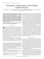
“Motorlab” Dynamics and Controls System<br />
Motor<br />
amplifier<br />
Power<br />
supply<br />
“Motorlab”<br />
Apparatus<br />
Interface to motion<br />
control card<br />
Mechanical<br />
System<br />
Detail<br />
Load<br />
encoder<br />
Load<br />
inertia<br />
System Description<br />
Load lock<br />
down screw<br />
Spring coupling<br />
Brushless motor<br />
Motor<br />
encoder<br />
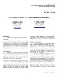
Below is a schematic representation of the motorlab system in a closed-loop position or velocity control<br />
configuration. There are two position sensors on the apparatus. The position of the motor inertia is measured using<br />
the motor encoder and the position of the load inertia is measured using the load encoder. This is done using<br />
hardware on the DSP motion control card that counts the pulses from the encoders. Each pulse corresponds to a<br />
certain increment of rotation. The velocities of the two inertias are measured using hardware on the MC4000<br />
motion control card that measures the time between pulses coming from the encoders. The motor amplifier has a<br />
control loop that measures and controls the electric current in the motor windings. This results in what is commonly<br />
known as a “torque controlled” motor, since the magnetic torque is proportional to the current in the windings. The<br />
DSP motion control card is interfaced to the motor amplifier through a +/-10V analog signal from a digital to analog<br />
converter (DAC) on the card. By varying the magnitude of this voltage from the DAC the current in the motor is<br />
varied. This voltage, which is proportional to the controlled current, serves as a current command for the current<br />
control loop in the amplifier. An additional sensor, not shown below, is the current sensor in the amplifier. This<br />
sensor is also read by the DSP card, using an analog to digital converter (ADC) to read the actual current measured<br />
by the amplifier. Although this signal is not used in the control loops on the DSP card, it is recorded for data<br />
analysis.<br />
DSP Card<br />
ic<br />
24 V Supply,<br />
and Motor<br />
Amp with<br />
Current Control<br />
V<br />
R<br />
i<br />
L<br />
+<br />
k b ω 1<br />
_<br />
T = kti<br />
θ 1<br />
J 1<br />
b 1<br />
k s<br />
b 2<br />
θ 2<br />
J 2<br />
θ<br />
1 , θ2,<br />
ω1,<br />
ω2<br />
1
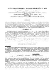
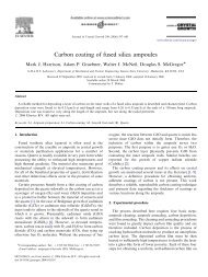
Several different configurations of the system can be utilized in experiments. Either sensor, the motor or load<br />
encoder, can be used for the feedback of the control loop. The selection is made in the software interface. The<br />
motor encoder is known as a “collocated” sensor since it is co-located with the input to the mechanical system, the<br />
motor torque. The load sensor is separated from the input to the system by a spring and is therefore known as a<br />
“non-collocated” sensor. In addition to varying which sensor is used, the mechanical system can be changed with<br />
the lock down screw and the spring coupling. Also, a choice can be made between velocity control or position<br />
control by selecting the appropriate control program. Any of the following mechanical models may be realized<br />
using the motorlab hardware and software.<br />
T<br />
θ 1<br />
θ 2<br />
T θ1<br />
T θ1<br />
J 1<br />
J 2<br />
J 1<br />
J 1<br />
b 1 k s<br />
b 2<br />
Fourth order system<br />
with a free integrator<br />
b 1 k s<br />
b 1<br />
Second order system<br />
Second order system<br />
with a free integrator<br />
T<br />
ω 1<br />
ω 2<br />
T<br />
ω 1<br />
T<br />
ω 1<br />
J 1<br />
J 2<br />
J 1<br />
J 1<br />
b 1<br />
k s<br />
b 2<br />
b 1<br />
k s<br />
b 1<br />
Third order system<br />
Second order system<br />
with a free differentiator<br />
First order system<br />
Software<br />
The software can be found in the “c:\motorlab” directory on the laboratory machines. All the needed functions<br />
and shortcuts to the executables can be found here. The “c:\motorlab\student data” directory can be used to store<br />
data files and gain files temporarily. It should be cleaned out at the end of the lab session. Students have<br />
read/write/delete access to this directory.<br />
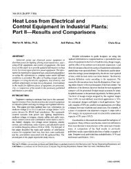
Control Software<br />
There are three different programs used to control the motorlab hardware. Each program consists of a GUI<br />
interface that runs on the host PC and a low-level control program that runs on the DSP microprocessor on the<br />
MC4000 motion control card. The PC’s processor and the DSP communicate over the PCI bus in the host computer.<br />
For the two programs that implement closed loop control, a PID controller is used. In addition the user has the<br />
option of including feedforward velocity and acceleration gains. Each of the three programs may be run by<br />
executing the host program, which loads the appropriate DSP program onto the motion control card and begins its<br />
execution. WARNING: The software will not function properly if more than one host program is running. The<br />
three programs are described below.<br />
MotorLabOL.exe<br />
This is the open loop program. The feedback sensors (encoders) are not actually used for<br />
closed loop control. The DAC output from the motion control card to the motor amplifier is<br />
determined directly by the wave command buttons and the jog buttons.<br />
MotorLabPosition.exe<br />
This is the position control program. The feedback sensors (encoders) are used to close<br />
the position control loop. The DAC output from the motion control card to the motor<br />
amplifier is determined by the controller algorithm, while the position command is<br />
determined by the wave command buttons and the jog buttons.<br />
2
MotorLabVelocity.exe<br />
This is the velocity control program. The feedback sensors (encoders) are used to close<br />
the velocity control loop. The DAC output from the motion control card to the motor<br />
amplifier is determined by the controller algorithm, while the velocity command is<br />
determined by the wave command buttons and the jog buttons.<br />
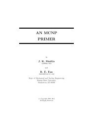
Menus for:<br />
•trapezoidal velocity<br />
profile parameters<br />
•controller gain<br />
changes<br />
•gain file saves<br />
•gain file loads<br />
Real time<br />
display of status<br />
Motion<br />
command<br />
buttons<br />
Data<br />
acquisition<br />
control<br />
Jogging<br />
buttons<br />
Choice of<br />
sensors for<br />
feedback loop<br />
Amplifier<br />
power control<br />
Encoder zeroing<br />
button<br />
Parameters for:<br />
•jogging<br />
•motion commands<br />
•and data storage<br />
Position Control Host-Computer Interface<br />
Velocity Control Host-Computer Interface<br />
Showing Gain-Change Dialog<br />
Open Loop Host-Computer Interface<br />
3
Data Acquisition<br />
When the “Store Data” button is pressed in the host GUI the software stores data from the dynamic system in a<br />
circular buffer. The buffer is 2048 data samples in length. After 2048 sample periods the buffer begins to be<br />
overwritten, and will continue to be overwritten as long as the “Store Data” button is depressed in the host program.<br />
Pressing either the “Save Data” button or the “Store Data” button again will stop data storage, leaving the last 2048<br />
data samples in the buffer. If for example the sample rate is set to 500 Hz, then the last 2048/500=4.096 seconds of<br />
data will be saved in the buffer. The data is saved to a file by pressing the “Save Data” button.<br />
The exception to the sampling scheme above occurs when one of the command buttons in the “One Shot<br />
Commands with Auto Save of Data” is pressed. In this case the command generation and the data storage execute<br />
until the buffer fills. Then the data is automatically stored to a data file named with the time and date from the<br />
computer clock.<br />
Nine pieces of data are stored at each time step (each sample period):<br />
TIME(sec) Command(deg/RPM/Amps) Theta1(deg) Theta2(deg) Vel1(RPM) Vel2(RPM) U(Amps) I(Amp) Extra()<br />
The TIME data begins at zero with the oldest data point in the buffer. The units of the Command depend upon<br />
which program is running: closed-loop position control, closed-loop velocity control, or the open loop program. The<br />
U variable is the commanded current to the amplifier, and the I variable is the measured current. The Extra variable<br />
is reserved for future use.<br />
Associated MATLAB functions for data analysis<br />
File: mlimport.m function data = mlimport(); Opens a dialogue to select a data file generated by the motor lab<br />
software. Returns the data in the selected file through a matrix with 9 columns and 2048 rows. The 9 columns of<br />
the matrix contain the following data:<br />
TIME(sec) Command(deg/RPM/Amps) Theta1(deg) Theta2(deg) Vel1(RPM) Vel2(RPM) U(Amps) I(Amp) Extra()<br />
example: data = mlimport;<br />
File: mlolplots.m function mlolplots(data,Iscale); Uses data generated by the motorlab openloop control software<br />
and imported using mlimport.m. Plots the motion variables along with the current command to the amplifier. If an<br />
"Iscale" argument is supplied then the commanded current values are scaled by the Iscale value in the plots.<br />
example: mlolplots(data); Does not scale the current command.<br />
example: mlolplots(data,Iscale); Multiplies commanded current values by Iscale.<br />
File: mlposplots.m function mlposplots(data); Uses data generated by the motorlab position control software that<br />
has been imported using mlimport(). Plots this data in several plots. example: mlposplots(data);<br />
File: mlvelplots.m function mlvelplots(data); Uses data generated by the motorlab velocity control software that<br />
has been imported using mlimport(). Plots this data in several plots. example: mlvelplots(data);<br />
File: trapprof.m function [x,v,t] =trapprof(DX,Vmax,Amax,DT) Trapezoidal-velocity motion profile generation<br />
Outputs: x=position vector, v=trapezoidal velocity vector, t=time vector<br />
Inputs: DX=distance to move, Vmax=maximum velocity, Amax=maximum acceleration, DT=time step for outputs<br />
example: [x,v,t] =trapprof(DX,Vmax,Amax,DT)<br />
Associated EXCEL programs<br />
Three EXCEL files/programs are also included in the motorlab directory: “Open Loop Plots.xls,” “Position<br />
Control Plots.xls,” and “Velocity Control Plots.xls.” Each of these files contains a Visual Basic GUI interface in<br />
the “HeaderSheet” sheet of the file. The GUI’s are used to import data files for the plot sheets. These files<br />
essentially implement the same plots as the three plot functions for MATLAB discussed above.<br />
4
Hardware Specifications<br />
Important Scaling Considerations<br />
• Motor Amplifier Scaling = 1 Amp/Volt (i.e. one volt from the DAC on the MC4000 is a one Amp command to<br />
the current loop in the motor amplifier). The plotting routines provided take this scaling into consideration.<br />
• Position is measured in degrees and velocity is measured in RPM. The output of the controller algorithm on the<br />
MC4000 is the DAC voltage, and is measured in Volts. Therefore, for example, the units of the proportional<br />
and derivate gains in the position controller would be Volts/deg and Volts*sec/deg, respectively. When<br />
multiplied by the amplifier scaling (1 Amp/Volt) these gains become Amps/deg and Amps*sec/deg. The units<br />
of the proportional gain in the velocity controller would be Volts/RPM (or Amps/RPM if amplifier scaling is<br />
included).<br />
Inertias<br />
Object<br />
Motor Rotor and Stainless Steel Stainless Steel Aluminum Aluminum Load<br />
Motor Encoder Coupling Collar Load Shaft Spacer for Load Load Inertia Encoder<br />
Approx. Inertia (g-cm 2 ) 110 13.04 1.423 0.079 81.91 0.83<br />
A Few Other Details<br />
• Max motor velocity with the amplifier used is about 4000 rpm<br />
• Max Data Acquisition Sample Rate = 10 kHz (the servo update rate of the DSP software)<br />
• Motor Encoder Resolution = 360/1600 = 0.225 deg/count<br />
• Load Encoder Resolution =360/2000=0.180 deg/count<br />
Velocity measurement<br />
The velocity is measured on the DSP motion control card using a timer to measure the time between encoder pulses<br />
( ω ≅ ∆θ<br />
/ ∆t<br />
). This results in a time delay in the velocity measurement that can become very significant at low<br />
velocity. This time delay can have a significant affect on a velocity controller and on the derivative term in a PID<br />
position controller. If for example the motor encoder is spinning at 20 rpm then the time delay would be<br />
0.225 deg rev 60sec<br />
∆t<br />
= ∆θ<br />
/ ω = ⋅ ⋅ = 0.002sec<br />
20 rev/min 360 deg min<br />
Theoretically, it is not possible to measure zero velocity.<br />
Specs from Motor Manufacturer’s Data Sheet<br />
LA052-040E Motor Dynamic Specs From Shinano Kenshi<br />
UNITS Value<br />
RATED POWER W 40<br />
RATED VOLTAGE VDC 24<br />
RATED SPEED rpm 3,000<br />
RATED TORQUE N-cm 12.7<br />
kgf-cm 1.3<br />
RATED CURRENT A 2.5<br />
TORQUE CONSTANT N-cm/A 5.0<br />
kgf-cm/A 0.51<br />
BACK EMF CONSTANT V/krpm 5.2<br />
PHASE RESISTANCE Ohm 1.18<br />
PHASE INDUCTANCE mH 4.4<br />
INSTANTANEOUS PEAK TORQUE N-cm 38.2<br />
MAX SPEED rpm 5,000<br />
ROTOR INERTIA g-cm 2 110<br />
POWER RATE kW/s 1.48<br />
MECHANICAL TIME CONSTANT ms 5.2<br />
ELECTRICAL TIME CONSTANT ms 3.7<br />
MASS kg 0.6<br />
5
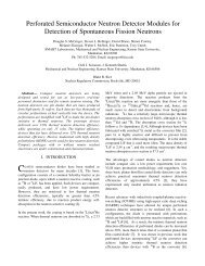
Current Control Loop Model<br />
The motor amplifier has a current control loop. As configured in the Motorlab apparatus this loop has a<br />
bandwidth of approximately 400 Hz. Using data acquired from step and sinusoidal responses the following two<br />
closed loop transfer functions have been identified as approximate models for the closed-loop current control<br />
dynamics.<br />
2<br />
ω n ( s + z)<br />
Ti<br />
= and<br />
2<br />
2<br />
z(<br />
s + 2ςω<br />
ns<br />
+ ω n )<br />
2<br />
ω n ( s + z)<br />
Tidelay<br />
=<br />
2<br />
z(<br />
s + 2ςωns<br />
+<br />
ω<br />
−td<br />
s<br />
e<br />
2<br />
n )<br />
where<br />
z = 170 ⋅ 2π<br />
(rad/<br />
sec)<br />
ωn<br />
= 230 ⋅ 2π<br />
(rad/<br />
sec)<br />
ς = 0.8<br />
td<br />
= 0.0002 (sec)<br />
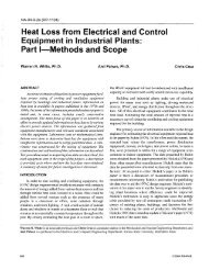
One of the models above contains a time delay while the other does not. In the following two figures the responses<br />
of these two models are compared with actual data acquired from one of the Motorlab systems. Both the step<br />
response and the frequency response models are shown.<br />
1.2<br />
Step Response of Current Control Loop<br />
1<br />
Current (Amp)<br />
0.8<br />
0.6<br />
0.4<br />
Command<br />
0.2<br />
Experimental Data<br />
Model w/o Time Delay<br />
Model with Time Delay<br />
0<br />
0 0.001 0.002 0.003 0.004 0.005<br />
Time (sec)<br />
2<br />
Frequency Response of Current Control Loop<br />
0<br />
Magnitude (dB)<br />
-2<br />
-4<br />
-6<br />
-8<br />
-10<br />
0<br />
Phase (deg)<br />
-45<br />
-90<br />
-135<br />
Experimental Data<br />
Model w/o Time Delay<br />
Model with Time Delay<br />
-180<br />
10 0 10 1 10 2 10 3<br />
Frequency (Hz)<br />
6
Schematic For the “Motorlab” Apparatus<br />
7
<strong>Manual</strong> for the Motor Amplifier
Model 503<br />
DC Brushless Servo Amplifier<br />
FEATURES<br />
• CE Compliance to<br />
89/336/EEC<br />
• Recognized Component<br />
to UL 508C<br />
• Complete torque ( current ) mode<br />
functional block<br />
• Drives motor with<br />
60° or 120° Halls<br />
• Single supply voltage<br />
18-55VDC<br />
• 5A continuous, 10A peak more<br />
than double the power output of<br />
servo chip sets<br />
• Fault protected<br />
Short-circuits from output to<br />
output, output to ground<br />
Over/under voltage<br />
Over temperature<br />
Self-reset or latch-off<br />
• 2.5kHz bandwidth<br />
• Wide load inductance range<br />
0.2 to 40 mH.<br />
• +5, +15V Hall power<br />
• Separate continuous, peak, and<br />
peak-time current limits<br />
• Surface mount technology<br />
APPLICATIONS<br />
• X-Y stages<br />
• Robotics<br />
• Automated assembly machinery<br />
• Component insertion machines<br />
THE OEM ADVANTAGE<br />
• NO POTS: Internal component<br />
header configures amplifier for<br />
applications<br />
• Conservative design for high<br />
MTBF<br />
• Low cost solution for small<br />
brushless motors to 1/3 HP<br />
PRODUCT DESCRIPTION<br />
Model 503 is a complete pwm servoamplifier for applications using DC<br />
brushless motors in torque ( current ) mode. It provides six-step commutation<br />
of three-phase DC brushless motors using 60° or 120° Hall<br />
sensors on the motor, and provides a full complement of features for<br />
motor control. These include remote inhibit/enable, directional enable<br />
inputs for connection to limit switches, and protection for both motor and<br />
amplifier.<br />
The /Enable input has selectable active level ( +5V or gnd ) to interface<br />
with most control cards.<br />
/Pos and /Neg enable inputs use fail-safe (ground to enable) logic.<br />
Power delivery is four-quadrant for<br />
bi-directional acceleration and deceleration of motors.<br />
Model 503 features 500W peak power output in a compact package<br />
using surface mount technology.<br />
An internal header socket holds components which configure the various<br />
gain and current limit settings to customize the 503 for different loads and<br />
applications.<br />
Separate peak and continuous current limits allow high acceleration<br />
without sacrificing protection against continuous overloads. Peak current<br />
time limit is settable to match amplifier to motor thermal limits.<br />
Header components permit compensation over a wide range of load<br />
inductances to maximize bandwidth with different motors.<br />
Package design places all connectors along one edge for easy connection<br />
and adjustment while minimizing footprint inside enclosures.<br />
High quality components and conservative ratings insure long service life<br />
and high reliability in industrial installations.<br />
A differential amplifier buffers the reference voltage input to reject<br />
common-mode noise resulting from potential differences between<br />
controller and amplifier grounds.<br />
Output short circuits and heatplate overtemperature cause the amplifier<br />
to latch into shutdown. Grounding the reset input will enable an autoreset<br />
from such conditions when this feature is desired.<br />
Corporate Offices: 410 University Avenue<br />
Westwood, MA 02090<br />
Telephone: (781) 329-8200<br />
Fax: (781) 329-4055<br />
E-mail: sales@copleycontrols.com<br />
http://www.copleycontrols.com<br />
221
Model 503<br />
DC Brushless Servo Amplifier<br />
FUNCTIONAL DIAGRAM<br />
MOMENTARY SWITCH RESETS FAULT<br />
WIRE RESET TO GROUND FOR SELF-RESET<br />
3 RESET<br />
1nF<br />
LED'S<br />
SHORT/O.T. R<br />
POWER FAULT R<br />
CH2 NORMAL G<br />
1.5 NF<br />
RH1<br />
+5V<br />
499K<br />
STATUS<br />
&<br />
CONTROL<br />
LOGIC<br />
8 +NORMAL<br />
NEG ENABLE<br />
4<br />
POS ENABLE<br />
5<br />
6 ENABLE<br />
J2 SIGNAL CONNECTOR<br />
REF(-) 10<br />
REF(+) 11<br />
CURRENT<br />
MONITOR<br />
OPEN = 120 DEG.<br />
GND = 60 DEG.<br />
HALLSELECT<br />
9<br />
2<br />
REF AMP<br />
10K<br />
RH7<br />
RH6<br />
10K<br />
1K<br />
33NF<br />
-<br />
+<br />
10K<br />
10K<br />
1nF<br />
CURRENT LIMIT<br />
SECTION<br />
100K<br />
RH3 RH5<br />
PEAK<br />
PEAK<br />
RH4 50K<br />
TIME<br />
RH3 RH5<br />
CONT<br />
Gv = 1<br />
470 PF<br />
2.2 MEG<br />
-<br />
+<br />
100 PF<br />
CURRENT<br />
ERROR<br />
AMP<br />
OUTPUT<br />
CURRENT<br />
SENSE<br />
+/-5V AT<br />
+/-10A<br />
PWM<br />
STAGE<br />
MOSFET<br />
"H"<br />
BRIDGE<br />
Gv = +HV<br />
10<br />
7 ENABLE POL<br />
GND<br />
1<br />
J2 SIGNAL CONNECTOR<br />
J1 MOTOR & POWER CONNECTOR<br />
U MOTOR<br />
1<br />
V<br />
2<br />
W<br />
3<br />
+HV<br />
4<br />
GND<br />
5<br />
U<br />
17<br />
HALLS<br />
V<br />
16<br />
W<br />
15<br />
+5<br />
14<br />
+15<br />
13<br />
GND<br />
18<br />
HALL<br />
LOGIC<br />
+5<br />
+15<br />
-15<br />
+HV<br />
DC / DC<br />
CONVERTER<br />
GROUND CASE FOR SHIELDING<br />
CASE GROUND<br />
NOT CONNECTED<br />
TO CIRCUIT GROUND<br />
POWER GROUND AND SIGNAL GROUNDS ARE COMMON<br />
TYPICAL CONNECTIONS<br />
CONTROLLER<br />
REF(-)<br />
REF(+)<br />
SIG GND<br />
10<br />
11<br />
12<br />
J2<br />
J1<br />
3<br />
2<br />
W<br />
V<br />
MOTOR<br />
DC POWER SUPPLY<br />
AC<br />
-<br />
GND<br />
5<br />
1<br />
U<br />
J1<br />
AC<br />
+<br />
SIG GND<br />
/NEG ENAB<br />
/POS ENAB<br />
/ENABLE<br />
+HV<br />
4<br />
1<br />
4<br />
5<br />
6<br />
J2<br />
J2<br />
13<br />
14<br />
15<br />
16<br />
17<br />
18<br />
+15 V<br />
+5 V<br />
Vcc<br />
W<br />
V<br />
U<br />
GND<br />
HALL<br />
SENSORS<br />
222<br />
Corporate Offices: 410 University Avenue<br />
Westwood, MA 02090<br />
Telephone: (781) 329-8200<br />
Fax: (781) 329-4055<br />
E-mail: sales@copleycontrols.com<br />
http://www.copleycontrols.com
Model 503<br />
DC Brushless Servo Amplifier<br />
APPLICATION INFORMATION<br />
To use the model 503 set up the internal header with the<br />
components that configure the transconductance, current<br />
limits, and load inductance. Current-limits and load<br />
inductance set up the amplifier for your particular motor,<br />
and the transconductance defines the amplifiers overall<br />
response in amps/volt that is required by your system.<br />
COMPONENT HEADER SETTINGS<br />
Use the tables provided to select values for your load and<br />
system. We recommend that you use these values as<br />
starting points, adjusting them later based on tests of the<br />
amplifier in your application.<br />
LOAD INDUCTANCE (RH1,CH2)<br />
Maximizes the bandwidth with your motor and supply<br />
voltage. First replace CH2 with a jumper (short). Adjust the<br />
value of RH1 using a step of 1A or less so as not to<br />
experience large signal slew-rate limiting. Select RH1 for<br />
the best transient response ( lowest risetime with minimal<br />
overshoot). Once RH1 has been set. choose the smallest<br />
value of CH2 that does not cause additional overshoot or<br />
degradation of the step response.<br />
TRANSCONDUCTANCE (RH6,7)<br />
The transconductance of the 503 is the ratio of output<br />
current to input voltage. It is equal to 10kΩ/RH6 (Amps/<br />
Volt). RH6,and RH7 should be the same value and should<br />
be 1% tolerance metal film type for good common-mode<br />
noise rejection.<br />
CURRENT LIMITS (RH3, 4, & 5)<br />
The amplifier operates at the 5A continuous, 10A peak<br />
limits as delivered. To reduce the limit settings, choose<br />
values from the tables as starting points, and test with your<br />
motor to determine final values. Limit action can be seen<br />
on current monitor when output current no longer changes<br />
in response to input signals. Separate control over peak,<br />
continuous, and peak time limits provides protection for<br />
motors, while permitting higher currents for acceleration.<br />
SETUP BASICS<br />
1. Set RH1 and CH2 for motor load inductance (see<br />
following section).<br />
2. Set RH3, 4, & 5 if current limits below standard values is<br />
required.<br />
3. Ground the /Enable (/Enable Pol open), /Pos Enable,<br />
and /Neg Enable inputs to signal ground.<br />
4. Connect the motor Hall sensors to J2 based on the<br />
manufacturers suggested signal names. Note that<br />
different manufacturers may use<br />
A-B-C, R-S-T, or U-V-W to name their Halls. Use the<br />
required Hall supply voltage (+5 or +15V). Note that<br />
there is a 30 mA limit at +5V. Encoders that put-out Hall<br />
signals typically consume 200-300 mA, so if these are<br />
used, then they must be powered from an external<br />
power supply.<br />
5. Connect J1-4,5 to a transformer-isolated source of DC<br />
power,<br />
+18-55V. Ground the amplifier and power supply with an<br />
additional wire from J1-5 to a central ground point.<br />
6. With the motor windings disconnected, apply power and<br />
slowly rotate the motor shaft. Observe the Normal (green)<br />
led. If the lamp blinks while turning then the 60/120°<br />
setting is incorrect. If J2-2 is open, then ground it and<br />
repeat the test. In order to insure proper operation, the<br />
correct Hall phasing of 60° or 120° must be made.<br />
6.Turn off the amplifier and connect the motor leads to<br />
J1-1,2,3 in U-V-W order. Power up the unit. Apply a<br />
sinusoidal reference signal of about 1 Hz. and 1Vrms<br />
between<br />
Ref(+) and Ref(-), J2-10,11.<br />
7. Observe the operation of the motor as the current monitor<br />
signal passes through zero. When phasing is correct the<br />
speed will be smooth at zero crossing and at low speeds. If<br />
it is not, then power-down and re-connect the motor.<br />
There are six possible ways to connect the motor windings,<br />
and only one of these will result in proper motor operation.<br />
The six combinations are listed in the table below. Incorrect<br />
phasing will result in erratic operation, and the motor may<br />
not rotate. When the correct combination is found, record<br />
your settings.<br />
J1-1 J1-2 J1-3<br />
#1 U V W<br />
#2 V W U<br />
#3 W U V<br />
#4 U W V<br />
#5 W V U<br />
#6 V U W<br />
GROUNDING & POWER SUPPLIES<br />
Power ground and signal ground are common ( internally<br />
connected ) in this amplifier. These grounds are isolated<br />
from the amplifier case which can then be grounded for best<br />
shielding while not affecting the power circuits.<br />
Currents flowing in the power supply connections will create<br />
noise that can appear on the amplifier grounds.<br />
This noise will be rejected by the differential amplifier at the<br />
reference input, but will appear at the digital inputs. While<br />
these are filtered, the lowest noise system will result when<br />
the power-supply capacitor is left floating, and each amplifier<br />
is grounded at its power ground terminal ( J1-5 ). In<br />
multiple amplifier configurations, always use separate<br />
cables to each amplifier, twisting these together for lowest<br />
noise emission. Twisting motor leads will also reduce<br />
radiated noise from pwm outputs. If amplifiers are more than<br />
1m. from power supply capacitor, use a small (500-1000µF.)<br />
capacitor across power inputs for local bypassing.<br />
Corporate Offices: 410 University Avenue<br />
Westwood, MA 02090<br />
Telephone: (781) 329-8200<br />
Fax: (781) 329-4055<br />
E-mail: sales@copleycontrols.com<br />
http://www.copleycontrols.com<br />
223
Model 503<br />
DC Brushless Servo Amplifier<br />
APPLICATION INFORMATION (CONT’D)<br />
COMPONENT HEADER<br />
J1<br />
J2<br />
LEDS<br />
HEADER LOCATION<br />
( COVER<br />
REMOVED )<br />
RH1<br />
CH2<br />
RH3<br />
RH4<br />
RH5<br />
RH6<br />
RH7<br />
WARNING!<br />
DISCONNECT POWER WHEN CHANGING HEADER<br />
COMPONENTS. REPLACE COVER BEFORE APPLYING<br />
POWER TO PREVENT CONTACT WITH LIVE PARTS.<br />
LOAD INDUCTANCE SETTING<br />
CONTINUOUS CURRENT LIMIT<br />
PEAK CURRENT TIME LIMIT<br />
PEAK CURRENT LIMIT<br />
REFERENCE GAIN SETTING<br />
NOTE: Components in dotted lines are<br />
not installed at factory<br />
CONTINUOUS CURRENT LIMIT (RH3)<br />
Icont (A)<br />
RH3 (Ω)<br />
5 open *<br />
4 20k<br />
3 8.2k<br />
2 3.9k<br />
1 1.5k<br />
INPUT TO OUTPUT GAIN SETTING ( RH6, RH7 )<br />
Note 1<br />
Example: Standard value of RH6 is 10kΩ, thus G = 1 A/V<br />
PEAK CURRENT LIMIT (RH5) Note 3<br />
Ipeak (A)<br />
RH5 (Ω)<br />
10 open *<br />
8 12k<br />
6 4.7k<br />
4 2k<br />
2 750<br />
LOAD INDUCTANCE SETTING (RH1 & CH2) Note 2<br />
Load (mH) RH1 CH2<br />
0.2 49.9 k 1.5 nF<br />
1 150 k 1.5 nF<br />
3 499 k 1.5 nF *<br />
10 499 k 3.3 nF<br />
33 499 k 6.8 nF<br />
40 499 k 10 nF<br />
PEAK CURRENT TIME-LIMIT (RH4) Note 4<br />
Tpeak (s) RH4 (Ω)<br />
0.5 open *<br />
0.4 10 M<br />
0.2 3.3 M<br />
0.1 1 M<br />
Times shown are for 10A step from 0A<br />
Notes:* Standard values installed at factory are shown in italics.<br />
1. RH6 & RH7 should be 1% resistors of same value.<br />
2. Bandwidth and values of RH1, CH2 are affected by supply voltage and load inductance. Final selection should be<br />
based on customer tests using actual motor at nominal supply voltage.<br />
3. Peak current setting should always be greater than continuous current setting.<br />
224<br />
4. Peak times will double when current changes polarity. Peak times decrease as continuous current increases.<br />
Corporate Offices: 410 University Avenue<br />
Westwood, MA 02090<br />
Telephone: (781) 329-8200<br />
Fax: (781) 329-4055<br />
E-mail: sales@copleycontrols.com<br />
http://www.copleycontrols.com
TECHNICAL SPECIFICATIONS<br />
Typical specifications @ 25°C ambient, +HV = +55VDC. Load = 200µH. in series with 1 ohm unless otherwise specified.<br />
OUTPUT POWER<br />
Peak power<br />
Unidirectional<br />
After direction change<br />
Continuous power<br />
OUTPUT VOLTAGE<br />
±10A @ 50V for 0.5 second, 500W<br />
±10A @ 50V for 1 second, 500W<br />
±5A @ 50V, 250W<br />
Vout = 0.97HV -(0.4)(Iout)<br />
MAXIMUM CONTINUOUS OUTPUT CURRENT<br />
Convection cooled, no conductive cooling<br />
±2A @ 35°C ambient<br />
Mounted on narrow edge, on steel plate, fan-cooled 400 ft/min ±5A @ 55°C<br />
LOAD INDUCTANCE<br />
Selectable with components on header socket<br />
200 µH to 40mH (Nominal, for higher inductances consult factory)<br />
BANDWIDTH<br />
Small signal<br />
-3dB @ 2.5kHz with 200µH load<br />
Note: actual bandwidth will depend on supply voltage, load inductance, and header component selection<br />
PWM SWITCHING FREQUENCY<br />
25kHz<br />
ANALOG INPUT CHARACTERISTICS<br />
Reference<br />
Differential, 20K between inputs with standard header values<br />
GAINS<br />
Input differential amplifier<br />
X1 as delivered. Adjustable via header components RH6, RH7<br />
PWM transconductance stage 1 A/V ( output vs. input to current limit stage )<br />
OFFSET<br />
Output offset current ( 0 V at inputs ) 20 mA max. ( 0.2% of full-scale )<br />
Input offset voltage 20 mV max ( for 0 output current, RH6,7 = 10kΩ )<br />
LOGIC INPUTS<br />
LOGIC OUTPUTS<br />
+Normal<br />
Logic threshold voltage<br />
/Enable<br />
/POS enable, /NEG enable<br />
/Reset<br />
/Enable Pol (Enable Polarity)<br />
INDICATORS (LED’s)<br />
Normal (green)<br />
Power fault (red)<br />
Short/Overtemp (red)<br />
CURRENT MONITOR OUTPUT<br />
DC POWER OUTPUTS<br />
+5VDC<br />
+15VDC<br />
PROTECTION<br />
Output short circuit (output to output, output to ground)<br />
Overtemperature<br />
Power supply voltage too low (Undervoltage)<br />
Power supply voltage too high (Overvoltage)<br />
POWER REQUIREMENTS<br />
DC power (+HV)<br />
Minimum power consumption<br />
Power dissipation at 5A output, 55VDC supply<br />
Power dissipation at 10A output, 55VDC supply<br />
THERMAL REQUIREMENTS<br />
Storage temperature range<br />
Operating temperature range<br />
MECHANICAL<br />
Size<br />
Weight<br />
CONNECTORS<br />
Power & motor<br />
Signal & Halls<br />
HI: ≥ 2.5V , LO: ≤1.0V, +5V Max on all logic inputs<br />
LO enables amplifier (/Enable Pol open) , HI inhibits; 50 ms turn-on delay<br />
LO enables positive and negative output currents, HI inhibits<br />
LO resets latching fault condition, ground for self-reset every 50 ms.<br />
LO reverses logic of /Enable input only (HI enables unit, LO inhibits)<br />
HI when unit operating normally, LO if overtemp, output short, disabled, or power supply (+HV) out of tolerance<br />
HI output voltage = 2.4V min at -3.2 mA max., LO output voltage = 0.5V max at 2 mA max.<br />
Note: Do not connect +Normal output to devices that operate > +5V<br />
ON = Amplifier enabled, no shorts or overtemp, power within limits<br />
ON = Power fault: +HV 55V<br />
ON = Output short-circuit or over-temperature condition<br />
±5V @ ±10A (2A/volt), 10kΩ, 3.3nF R-C filter<br />
30mA (Includes power for Hall sensors)<br />
10mA<br />
Total power from all outputs not to exceed 200mW.<br />
Latches unit OFF (self-reset if /RESET input grounded)<br />
Shutdown at 70°C on heatplate (Latches unit OFF)<br />
Shutdown at +HV < 18VDC (operation resumes when power >18VDC)<br />
Shutdown at +HV > 55VDC (operation resumes when power
Model 503<br />
DC Brushless Servo Amplifier<br />
OUTLINE DIMENSIONS<br />
Dimensions in inches (mm.)<br />
(19.1)<br />
4.75<br />
(120.7)<br />
0.75<br />
(3.0)<br />
0.17<br />
2.00<br />
(50.8)<br />
3.27<br />
(83.1)<br />
(14)<br />
4.50<br />
(114.3)<br />
0.55<br />
1.28<br />
(32.5)<br />
ORDERING GUIDE<br />
Model 503<br />
5A Continuous, 10A Peak, +18-55VDC Brushless Servoamplifier<br />
OTHER BRUSHLESS AMPLIFIERS<br />
Model 505<br />
Same power output as 503. Adds Hall / Encoder tachometer feature for velocity loop<br />
operation.<br />
5001 Series Six models covering +24-225VDC operation, 5-15A continuous, 10-30A peak.<br />
With optional Hall / Encoder tachometer, and brushless tachometer features.<br />
Model 513R<br />
Resolver interface for trapezoidal-drivemotors. Outputs A/B quadrature encoder signals<br />
and analog tachometer signal for velocity loop operation. +24-180VDC operation, 13A<br />
continuous, 26A peak.<br />
226<br />
Corporate Offices: 410 University Avenue<br />
Westwood, MA 02090<br />
Telephone: (781) 329-8200<br />
Fax: (781) 329-4055<br />
E-mail: sales@copleycontrols.com<br />
http://www.copleycontrols.com
Data Sheet for the MC4000 DSP Motion<br />
Control Card
MC4000<br />
PCI-Bus<br />
The Versatile<br />
Motion Control Board<br />
with Easy-to-Use Software<br />
The MC4000 is Precision MicroDynamics’ multi-axis, PCI-Bus motion control DSP board. It is ideal<br />
for both Original Equipment Manufacturers (OEMs) and Test and Measurement applications.<br />
ASED ULTI XIS<br />
OTION ONTROL<br />
PC-B M -A<br />
DSP M C<br />
Four off-the-shelf versions of the<br />
MC4000 are offered: the<br />
MC4000-PRO, four servos and<br />
four steppers; the MC4000-<br />
LITE, four servos; the MC4000-<br />
STEP, four closed-loop steppers<br />
and four open-loop steppers; and<br />
the MC4000-DUAL, four dualencoder<br />
servos.<br />
MC4000<br />
Version<br />
PRO<br />
LITE<br />
STEP<br />
DUAL<br />
Servos<br />
*Dual Encoder Axes<br />
The MC4000 uses a 32-bit floating-point DSP that performs path planning, feedback regulation and<br />
other real-time computations, freeing the host PC for process application and graphical user interface<br />
( GUI) software.<br />
The MC4000 is supported by powerful development software: MotionSuite and MotionSuite-<br />
PRO. MotionSuite includes: MCI-SoftLIB, easy-to-use, thread-safe C-library of motion control<br />
functions; and MotionTools, easy-to-use GUI for machine tuning and set up.<br />
MotionSuite-PRO provides DSP programming capability for the MC8000. MotionSuite-PRO<br />
includes: LIBeRTy real-time multi-tasking software; CMC-SoftLIB, a C-library of motion<br />
control routines; SHARC-Trig, a mathematics C-library; and MotionTools.<br />
Application areas for the MC4000 include: semiconductor processing, material handling and test, CNC<br />
machine tool control, automotive test and measurement, aerospace, medical equipment, industrial<br />
materials processing, and food packaging and processing.<br />
4<br />
4<br />
-<br />
4*<br />
Open-loop<br />
Steppers<br />
4<br />
-<br />
4<br />
-<br />
Closed-loop<br />
Steppers<br />
-<br />
-<br />
4<br />
-<br />
Analog<br />
Inputs<br />
4<br />
-<br />
-<br />
4<br />
Position<br />
Cap./Com.<br />
4<br />
-<br />
-<br />
4<br />
Custom modifications to standard DSP executables and FPGA firmware are performed for qualified<br />
OEMs.<br />
PRECISION<br />
M I C R O<br />
DYNAMICS<br />
07/2001<br />
Precision MicroDynamics, Inc., #3 - 512 Frances Ave., Victoria, B.C., Canada, V8Z 1A1, Tel. 250-382-7249, Fax. 250-382-1830, Web. Http://www.pmdi.com
Hardware<br />
MC4000-PRO Overview<br />
The MC4000-PRO is a DSP-based motion control board that<br />
communicates with the Host PC through the PCI bus. The card<br />
supports data rates with the host PC as high as 7.2 MBytes/s . The<br />
core of the MC4000-PRO is its 32-bit floating-point DSP<br />
processor. The standard memory configuration is 48 bits wide and<br />
includes 20K words of on-chip SRAM, 256K words of on-board<br />
SRAM and 330Kwords of FLASH memory.<br />
The MC4000-PRO’s 2 external connectors are arranged into<br />
four groups, with each group having 30 physical contacts.<br />
I/O Type Number<br />
Details<br />
Encoders<br />
4 - A, B, Z, A* , B* and Z*<br />
Analog In<br />
4 - ADC differential line<br />
Out<br />
8 - DAC<br />
Digital In<br />
24 - user programmable<br />
Out<br />
8 - user programmable<br />
High-speed 16 - Stepper outputs, auxiliary<br />
I/O<br />
encoders and registration<br />
Digital Signal Processor<br />
The DSP is Analog Devices’ 32-bit ADSP-21061 SHARC<br />
processor running at 40MHz with 20K words of on-chip memory.<br />
Other SHARC DSPprocessors available include:<br />
DSP Type On-board SRAM Other details<br />
ADSP-21060 80K words<br />
Linkports<br />
ADSP-21062 40K words<br />
Linkports<br />
Nonvolatile Memory<br />
Permanent memory storage for stand-alone operations is<br />
provided. The board comes with 330K words of FLASH memory<br />
for storage of machine parameters and programs.<br />
Quadrature Encoders<br />
The quadrature encoder inputs support single-ended and<br />
differential encoder signals. +5V and 12V are available for<br />
encoder power. The standard encoder input frequency is 10 MHz<br />
edge rate after 4X decoding (20 & 40MHz options are available).<br />
Analog<br />
Each group has a 14-bit (65,536 Levels) differential analog input<br />
and two 16-bit (16,384 Levels) outputs. These signals sample at a<br />
rate of 88kHz. Each group has the following:<br />
Analog<br />
Inputs<br />
Outputs<br />
Digital<br />
Quantity<br />
1<br />
2<br />
SYNC and WDOG<br />
Name<br />
ADC<br />
DAC A and B<br />
Resolution<br />
14 bits<br />
16 bits<br />
Range<br />
± 10V<br />
± 10V<br />
Each group has 6 inputs, 2 outputs and 4 high-speed lines for a<br />
total of 48 Digital I/O lines. Unreserved lines can be programmed<br />
to meet OEM requirements. Each group has the following:<br />
Digital I/O* Quantity<br />
Typical Use<br />
Inputs 6 HOME, LIM-, LIM+<br />
Outputs 2 AmpEnable<br />
Stepper Motor- Pulse or Dir,<br />
High-speed 4 Position Capture or Compare,<br />
and Auxiliary A and B.<br />
*TTL compatible (sink and source 10 mA)<br />
The SYNC signal can be passed between multiple MC4000-<br />
PRO boards for synchronization of motion control or data<br />
acquisition. If the WDOG times out, the user can program any<br />
number of discrete events to take place (ex. emergency stop).<br />
Linkport<br />
A ten-pin connector contains the WDOG and SYNC signals,<br />
along with the Linkport connections, enabling communication<br />
between two separate MC4000-PRO DSPs directly (transfer<br />
rates up to 160Mbits/sec). This is an advanced feature available<br />
with theADSP-21060 orADSP-21062 options.<br />
Software<br />
Two development software suites are available for the MC4000.<br />
These are (i) MotionSuite and (ii) MotionSuite-PRO.<br />
MotionSuite<br />
Register Access is offered for Microsoft Windows operating<br />
systems. This library provides functions for reading and writing<br />
the board’s registers.<br />
MotionTools is a GUI application program used to set up, and<br />
tune motion control for the MC4000. Evaluate MotionTools for<br />
free over the Internet. After downloading MotionTools you will<br />
be able to control servomotors directly over the Internet. To learn<br />
more visit http://www.pmdi.com.<br />
MCI-SoftLIB high-level motion control C-library contains a set<br />
of functions that accesses the services of PMDi’s DSP-based<br />
motion control cards.<br />
Initialization File is a text-based file that sets motion control<br />
parameters for use by the MCI-SoftLIB library.<br />
MotionSuite-PRO<br />
MotionSuite-PRO provides all of the features and components of<br />
MotionSuite, but adds the capability of programming at the DSP<br />
level. It is distributed with the additional software components:<br />
CMC-SoftLIB, LIBeRTy and SHARC-Trig.<br />
CMC-SoftLIB is a comprehensive software library of C-<br />
language routines for motion control application development.<br />
LIBeRTy is PMDi’s real-time, multi-tasking kernel for use<br />
with Analog Devices’ SHARC DSP Processors.<br />
SHARC-Trig is an optimized trigonometry C-library.<br />
Specifications<br />
Computer Compatibility<br />
PCI Bus, 4.25in. high by 8.25in. long<br />
Digital Signal Processor and Memory<br />
Analog Devices’ADSP-2106X SHARC DSP<br />
128K words of 48-Bit on-board SRAM<br />
330K words of 48-Bit on-board FLASH memory<br />
SYNC<br />
Synchronizes DAC output, ADC and encoder input<br />
SYNC generated by on-board timer or software<br />
Programmable Interval Timer<br />
0.25<br />
s to 512 seconds with 0.12<br />
s resolution<br />
Can generate SYNC signal and/or PC interrupts<br />
Watchdog Timer<br />
3.85<br />
s to 125ms<br />
Forces DAC outputs to 0 Volts on timeout and digital output<br />
to low for emergency shutdown<br />
24-bit up-down counters. A,B,Z inputs, invertible for<br />
phasing and universal index pulse, digitally filtered<br />
Quadrature Encoder Input Channels<br />
Precision MicroDynamics, Inc., #3 - 512 Frances Ave., Victoria, B.C., Canada, V8Z 1A1, Tel. 250-382-7249, Fax. 250-382-1830, Web. Http://www.pmdi.com<br />
PMDi
Preload in hardware by index pulse or by software register<br />
Each encoder axis input configurable for differential or<br />
single ended termination<br />
Power for +5V and +12V encoders<br />
Up to 40MHz maximum input edge rate<br />
D/A Channels (16-bit)<br />
Maximum output rate 88kHz<br />
Accuracy ±1 LSB<br />
Voltage output range ±10V<br />
A/D Channels (14-bit)<br />
Maximum sampling rate 88kHz<br />
Accuracy ±1 LSB<br />
Voltage input range ±10V<br />
Digital Inputs<br />
Digital inputs typically used for machine limits and home<br />
TTL Level, 10mA sink<br />
Pin-outs<br />
Four off-the-shelf versions of the MC4000 are available.<br />
These are the MC4000-PRO, MC4000-LITE,<br />
MC4000-STEP and MC4000-DUAL. Each version has<br />
four standard 60-pin IDC connectors. Each connector is<br />
logically separated into two 30-pin groups, with each<br />
group supporting one motion axis (except for the PRO<br />
and STEPversions that have two axes per group for a total<br />
of 8 axes).<br />
Digital Outputs<br />
Digital outputs, usually used as amp enable and emergency<br />
shutdown.<br />
TTL Level, 10mA source<br />
Stepper Motor Outputs<br />
Pulse and direction bits<br />
2MHz max (1 Hz resolution)<br />
High-Speed Digital I/O<br />
Stepper motor outputs (step and direction)<br />
Position capture inputs or compare outputs<br />
Auxiliary encoder inputs (A and B)<br />
Unreserved high speed I/O for OEMs<br />
Additional functions for qualified OEM customers<br />
PWM Outputs<br />
Temposonics Inputs<br />
Handwheel Inputs<br />
MC4000<br />
connectors<br />
1 3<br />
0<br />
J17<br />
2<br />
PMDi<br />
Group0<br />
MC4000-PRO MC4000-LITE MC4000-STEP MC4000-DUAL<br />
PIN FUNCTION<br />
1<br />
+5V<br />
2<br />
GND<br />
3<br />
A<br />
4<br />
A*<br />
5<br />
B<br />
6<br />
B*<br />
7<br />
Z<br />
8<br />
Z*<br />
9<br />
+12V<br />
10<br />
GND<br />
11<br />
DIN0<br />
12<br />
DIN1<br />
13<br />
DIN2<br />
14<br />
DIN3<br />
15<br />
DIN4<br />
16<br />
DIN5<br />
17<br />
GND<br />
18<br />
+5V<br />
19 DOUT0<br />
20 DOUT1<br />
21<br />
GND<br />
22 HSD0<br />
23 HSD1<br />
24 HSD2<br />
25 HSD3<br />
26 AGND<br />
27 DAC B<br />
28 DAC A<br />
29<br />
AD+<br />
30<br />
AD-<br />
DESCRIPTION<br />
DESCRIPTION<br />
+5V Power for Encoders<br />
+5V Power for Encoders<br />
Encoder GND<br />
Encoder GND<br />
Encoder Channel A<br />
Encoder Channel A<br />
Encoder Channel A Complement Encoder Channel A Complement<br />
Encoder Channel B<br />
Encoder Channel B<br />
Encoder Channel B Complement Encoder Channel B Complement<br />
Encoder Index Pulse<br />
Encoder Index Pulse<br />
Encoder Index Pulse Complement Encoder Index Pulse Complement<br />
+12V Power for Encoders<br />
+12V Power for Encoders<br />
Digital Ground<br />
Digital Ground<br />
HOME1<br />
HOME1<br />
LIM1+<br />
LIM1+<br />
LIM1-<br />
LIM1-<br />
HOME2<br />
DIN3<br />
LIM2+<br />
DIN4<br />
LIM2-<br />
DIN5<br />
Digital Ground<br />
Digital Ground<br />
+5V from PC<br />
+5V from PC<br />
Amp Enable 1<br />
Amp Enable 1<br />
Amp Enable 2<br />
DOUT1<br />
Digital Ground<br />
Digital Ground<br />
Stepper Motor- Pulse 1<br />
NC<br />
Stepper Motor- Direction 1<br />
NC<br />
Position Compare Output<br />
NC<br />
Position Capture Input<br />
NC<br />
Analog Ground<br />
Analog Ground<br />
Analog Output B<br />
NC<br />
Analog Output A<br />
Analog Output A<br />
Analog Input +ve Diferential Line NC<br />
Analog Input +ve Diferential Line NC<br />
DESCRIPTION<br />
DESCRIPTION<br />
+5V Power for Encoders<br />
+5V Power for Encoders<br />
Encoder GND<br />
Encoder GND<br />
Encoder Channel A<br />
Encoder Channel A<br />
Encoder Channel A Complement Encoder Channel A Complement<br />
Encoder Channel B<br />
Encoder Channel B<br />
Encoder Channel B Complement Encoder Channel B Complement<br />
Encoder Index Pulse<br />
Encoder Index Pulse<br />
Encoder Index Pulse Complement Encoder Index Pulse Complement<br />
+12V Power for Encoders<br />
+12V Power for Encoders<br />
Digital Ground<br />
Digital Ground<br />
HOME1<br />
HOME1<br />
LIM1+<br />
LIM1+<br />
LIM1-<br />
LIM1-<br />
HOME2<br />
DIN3<br />
LIM2+<br />
DIN4<br />
LIM2-<br />
DIN5<br />
Digital Ground<br />
Digital Ground<br />
+5V from PC<br />
+5V from PC<br />
Amp Enable 1<br />
Amp Enable 1<br />
Amp Enable 2<br />
DOUT1<br />
Digital Ground<br />
Digital Ground<br />
Stepper Motor- Pulse 1<br />
Aux. Encoder Channel A<br />
Stepper Motor- Direction 1<br />
Aux. Encoder Channel B<br />
Stepper Motor- Pulse 2<br />
Position Compare Output<br />
Stepper Motor- Direction 2<br />
Position Capture Input<br />
NC<br />
Analog Ground<br />
NC<br />
Analog Output B<br />
NC<br />
Analog Output A<br />
NC<br />
Analog Input +ve Diferential Line<br />
NC<br />
Analog Input +ve Diferential Line<br />
* Pin-outs shown for Group0 only (Connector J17 pin 1-30). Functions for Group1 to Group3 are the same.<br />
Precision MicroDynamics, Inc., #3 - 512 Frances Ave., Victoria, B.C., Canada, V8Z 1A1, Tel. 250-382-7249, Fax. 250-382-1830, Web. http://www.pmdi.com
System Configuration<br />
PMDi<br />
MC4000<br />
WH-60 †<br />
Group0 and 1<br />
2 WH-60 cables connected to<br />
‡<br />
2 Breakout60 interconnect boards<br />
Group2 and 3<br />
WH-60 †<br />
Amplifiers*<br />
Encoders<br />
Sensors<br />
Relays<br />
Servos<br />
Steppers<br />
Switches<br />
† also available in shielded version (WHS-60)<br />
‡ regular terminal block available (TERM/60)<br />
* PMDi Linear amplifier available (BTA-XXV-6A)<br />
Ordering Information<br />
MC8000-PRO*<br />
-LITE*<br />
-STEP*<br />
-DUAL*<br />
WH-60<br />
WHS-60<br />
BreakOut60<br />
TERM/60<br />
SYNC/10-ZZ<br />
DNG-9<br />
MotionSuite<br />
MotionSuite-PRO<br />
4 servo axes and 4 stepper axes motion control and data acquisition board<br />
4 servo axes motion control board<br />
4 closed-loop stepper axes and 4 open-loop stepper axes motion control board<br />
4 servo axes dual-encoder motion control and data acquisition board<br />
60 pin ribbon cable assembly (for two axes)<br />
60 pin shielded cable assembly (for two axes)<br />
Breakout board with opto-isolation (for two axes)<br />
60 contact screw-terminal break-out board (for two axes)<br />
10 pin SYNC connector cable, ZZ the number of connectors = number of boards synchronized<br />
Encoder line fault detection circuitry for open-circuit, short-circuit, and voltage level<br />
MotionTools, MCI-SoftLIB, and Register Access libraries<br />
MotionSuite plus LIBeRTy, SHARC-Trig, and CMC-SoftLIB<br />
* Register Access libraries included.<br />
Note: MC8000 boards using Linkports require non-standard DSP chips. Call Precision MicroDynamics for information.<br />
Warranty: The MC8000 is warranted according to the Terms and Conditions of the Sale and is effective for ONE YEAR after shipment.<br />
Representative's Information<br />
PRECISIONMICRODYNAMICS<br />
#3-512FrancesAvenue•Victoria•B.C.<br />
Canada•V8Z1A1<br />
Tel. 250-382-7249• Fax.250-382-1830<br />
Web. http://www.pmdi.com Email.info@pmdi.com<br />
©2001 Precision MicroDynamics, Inc., Specifications may change without notice.