ïï Radiation Shielding and Radiological Protection - Kansas State ...
ïï Radiation Shielding and Radiological Protection - Kansas State ...
ïï Radiation Shielding and Radiological Protection - Kansas State ...
- No tags were found...

You also want an ePaper? Increase the reach of your titles
YUMPU automatically turns print PDFs into web optimized ePapers that Google loves.
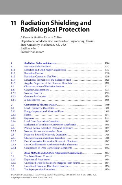
11 <strong>Radiation</strong> <strong>Shielding</strong> <strong>and</strong><strong>Radiological</strong> <strong>Protection</strong>J. Kenneth Shultis ⋅ Richard E. FawDepartment of Mechanical <strong>and</strong> Nuclear Engineering, <strong>Kansas</strong><strong>State</strong> University, Manhattan, KS, USAjks@ksu.edufawre@triad.rr.com1 <strong>Radiation</strong> Fields <strong>and</strong> Sources ................................................ 13161.1 <strong>Radiation</strong> Field Variables ........................................................... 13171.1.1 Direction <strong>and</strong> Solid Angle Conventions ......................................... 13171.1.2 <strong>Radiation</strong> Fluence ................................................................... 13181.1.3 <strong>Radiation</strong> Current or Net Flow .................................................... 13191.1.4 Directional Properties of the <strong>Radiation</strong> Field ................................... 13201.1.5 Angular Properties of the Flow <strong>and</strong> Flow Rate .................................. 13201.2 Characterization of <strong>Radiation</strong> Sources ........................................... 13211.2.1 General Considerations ............................................................ 13211.2.2 Neutron Sources ..................................................................... 13221.2.3 Gamma-Ray Sources................................................................ 13281.2.4 X-Ray Sources ....................................................................... 13362 ConversionofFluencetoDose............................................... 13392.1 Local Dosimetric Quantities ....................................................... 13402.1.1 Energy Imparted <strong>and</strong> Absorbed Dose ............................................ 13402.1.2 Kerma ................................................................................. 13412.1.3 Exposure .............................................................................. 13412.1.4 Local Dose Equivalent Quantities................................................. 13422.2 Evaluation of Local Dose Conversion Coefficients ............................. 13452.2.1 Photon Kerma, Absorbed Dose, <strong>and</strong> Exposure ................................. 13452.2.2 Neutron Kerma <strong>and</strong> Absorbed Dose ............................................. 13452.3 Phantom-Related Dosimetric Quantities ........................................ 13462.3.1 Characterization of Ambient <strong>Radiation</strong> .......................................... 13462.3.2 Dose Conversion Factors for Geometric Phantoms ............................ 13472.3.3 Dose Coefficients for Anthropomorphic Phantoms............................ 13492.3.4 Comparison of Dose Conversion Coefficients .................................. 13523 Basic Methods in <strong>Radiation</strong> Attenuation Calculations..................... 13533.1 The Point-Kernel Concept ......................................................... 13533.1.1 Exponential Attenuation ........................................................... 13543.1.2 Uncollided Dose from a Monoenergetic Point Source ......................... 13543.2 Uncollided Doses for Distributed Sources ....................................... 13563.2.1 The Superposition Procedure ...................................................... 1356Dan Gabriel Cacuci (ed.), H<strong>and</strong>book of Nuclear Engineering, DOI 10.1007/978-0-387-98149-9_11,© Springer Science+Business Media LLC 2010
1314 11<strong>Radiation</strong><strong>Shielding</strong> <strong>and</strong> <strong>Radiological</strong> <strong>Protection</strong>3.2.2 Example Calculations for Distributed Sources .................................. 13564 Photon Attenuation Calculations............................................ 13594.1 The Photon Buildup-Factor Concept ............................................. 13594.2 Isotropic, Monoenergetic Sources in Infinite Media ........................... 13604.3 Buildup Factors for Point <strong>and</strong> Plane Sources .................................... 13624.3.1 Empirical Approximations for Buildup Factors ................................. 13654.3.2 Point-Kernel Applications of Buildup Factors................................... 13654.4 Buildup Factors for Heterogenous Media ........................................ 13694.4.1 Boundary Effects in Finite Media ................................................. 13694.4.2 Treatment of Stratified Media ..................................................... 13704.5 Broad-Beam Attenuation of Photons ............................................. 13724.5.1 Attenuation Factors for Photon Beams........................................... 13724.5.2 Attenuation of Oblique Beams of Photons....................................... 13724.5.3 Attenuation Factors for X-Ray Beams ............................................ 13734.5.4 The Half-Value Thickness .......................................................... 13764.6 Shield Heterogeneities .............................................................. 13764.6.1 Limiting Case for Small Discontinuities ......................................... 13774.6.2 Small R<strong>and</strong>omly Distributed Discontinuities ................................... 13785 Neutron <strong>Shielding</strong> ............................................................ 13785.1 Neutron Versus Photon Calculations ............................................. 13795.2 Fission Neutron Attenuation by Hydrogen ...................................... 13795.3 Removal Cross Sections ............................................................ 13825.4 Extensions of the Removal Cross Section Model ............................... 13845.4.1 Effect of Hydrogen Following a Nonhydrogen Shield.......................... 13845.4.2 Homogenous Shields................................................................ 13855.4.3 Energy-Dependent Removal Cross Sections .................................... 13865.5 Fast-Neutron Attenuation Without Hydrogen .................................. 13875.6 Intermediate <strong>and</strong> Thermal Fluences .............................................. 13895.6.1 Diffusion Theory for Thermal Neutron Calculations .......................... 13895.6.2 Fermi Age Treatment for Thermal <strong>and</strong> Intermediate-Energy Neutrons ..... 13915.6.3 Removal-Diffusion Techniques ................................................... 13925.7 Capture-Gamma-Photon Attenuation ........................................... 13945.8 Neutron <strong>Shielding</strong> with Concrete ................................................. 13965.8.1 Concrete Slab Shields ............................................................... 13966 The Albedo Method ........................................................... 14006.1 Differential Number Albedo ....................................................... 14016.2 Integrals of Albedo Functions ..................................................... 14026.3 Application of the Albedo Method ............................................... 14026.4 Albedo Approximations ............................................................ 14036.4.1 Photon Albedos...................................................................... 14036.4.2 Neutron Albedos .................................................................... 14057 Skyshine....................................................................... 14077.1 Approximations for the LBRF ..................................................... 14087.1.1 Photon LBRF Approximation ..................................................... 14097.1.2 Neutron LBRF Approximation .................................................... 1409
<strong>Radiation</strong> <strong>Shielding</strong> <strong>and</strong> <strong>Radiological</strong> <strong>Protection</strong> 1113157.2 Open Silo Example .................................................................. 14097.3 Shielded Skyshine Sources ......................................................... 14117.4 Computational Resources for Skyshine Analyses ............................... 14128 <strong>Radiation</strong> Streaming Through Ducts ........................................ 14128.1 Characterization of Incident <strong>Radiation</strong> .......................................... 14138.2 Line-of-Sight Component for Straight Ducts ................................... 14148.2.1 Line-of-Sight Component for the Cylindrical Duct ............................ 14148.2.2 Line-of-Sight Component for the Rectangular Duct ........................... 14158.3 Wall-Penetration Component for Straight Ducts ............................... 14158.4 Single-Scatter Wall-Reflection Component...................................... 14168.5 Photons in Two-Legged Rectangular Ducts ..................................... 14188.6 Neutron Streaming in Straight Ducts............................................. 14208.7 Neutron Streaming in Ducts with Bends ........................................ 14218.7.1 Two-Legged Ducts .................................................................. 14218.7.2 Neutron Streaming in Ducts with Multiple Bends ............................. 14238.8 Empirical <strong>and</strong> Experimental Results.............................................. 14239 Shield Design ................................................................. 14249.1 <strong>Shielding</strong> Design <strong>and</strong> Optimization .............................................. 14249.2 <strong>Shielding</strong> Materials .................................................................. 14259.2.1 Natural Materials .................................................................... 14259.2.2 Concrete .............................................................................. 14279.2.3 Metallic <strong>Shielding</strong> Materials ....................................................... 14289.2.4 Special Materials for Neutron <strong>Shielding</strong> ......................................... 14289.2.5 Materials for Diagnostic X-Ray Facilities ........................................ 14299.3 A Review of Software Resources .................................................. 14299.4 <strong>Shielding</strong> St<strong>and</strong>ards ................................................................. 143010 Health Physics ................................................................ 143010.1 Deterministic Effects from Large Acute Doses.................................. 143110.1.1 Effects on Individual Cells ......................................................... 143110.1.2 Deterministic Effects in Organs <strong>and</strong> Tissues .................................... 143110.1.3 Potentially Lethal Exposure to Low-LET <strong>Radiation</strong> ............................ 143210.2 Hereditary Illness.................................................................... 143310.2.1 Classification of Genetic Effects ................................................... 143410.2.2 Estimates of Hereditary Illness Risks ............................................. 143510.3 Cancer Risks from <strong>Radiation</strong> Exposures ......................................... 143510.3.1 Estimating Radiogenic Cancer Risks ............................................. 143610.4 The Dose <strong>and</strong> Dose-Rate Effectiveness Factor .................................. 143710.4.1 Dose–Response Models for Cancer............................................... 143710.4.2 Average Cancer Risks for Exposed Populations ................................. 143810.5 <strong>Radiation</strong> <strong>Protection</strong> St<strong>and</strong>ards ................................................... 143910.5.1 Risk-Related Dose Limits .......................................................... 144010.5.2 The 1987 NCRP Exposure Limits.................................................. 1441References ..................................................................... 1442
1316 11<strong>Radiation</strong><strong>Shielding</strong> <strong>and</strong> <strong>Radiological</strong> <strong>Protection</strong>Abstract: This chapter deals with shielding against nonionizing radiation, specifically gammarays <strong>and</strong> neutrons with energies less than about 10 MeV, <strong>and</strong> addresses the assessment of healtheffects from exposure to such radiation. The chapter begins with a discussion of how to characterizemathematically the energy <strong>and</strong> directional dependence of the radiation intensity <strong>and</strong>,similarly, the nature <strong>and</strong> description of radiation sources. What follows is a discussion of howneutrons <strong>and</strong> gamma rays interact with matter <strong>and</strong> how radiation doses of various types arededuced from radiation intensity <strong>and</strong> target characteristics. This discussion leads to a detaileddescription of radiation attenuation calculations <strong>and</strong> dose evaluations, first making use ofthe point-kernel methodology <strong>and</strong> then treating the special cases of “skyshine” <strong>and</strong> “albedo”dose calculations. The chapter concludes with a discussion of shielding materials, radiologicalassessments, <strong>and</strong> risk calculations.1 <strong>Radiation</strong> Fields <strong>and</strong> SourcesThe transmission of directly <strong>and</strong> indirectly ionizing radiation through matter <strong>and</strong> its interactionwith matter is fundamental to radiation shielding design <strong>and</strong> analysis. Design <strong>and</strong>analysis are but two sides of the same coin. In design, the source intensity <strong>and</strong> permissibleradiationdoseordoserateatsomelocationarespecified,<strong>and</strong>thetaskistodeterminethetype <strong>and</strong> configuration of shielding that is needed. In analysis, the shielding material is specified,<strong>and</strong> the task is to determine the dose, given the source intensity, or the latter, given theformer.The radiation is conceptualized as particles – photons, electrons, neutrons, <strong>and</strong> so on. Theterm radiation field refers collectively to the particles <strong>and</strong> their trajectories in some region ofspace or through some boundary, either per unit time or accumulated over some period of time.Characterization of the radiation field, for any one type of radiation particle, requires adetermination of the spatial variation of the joint distribution of the particle’s energy <strong>and</strong> direction.In certain cases, such as those encountered in neutron scattering experiments, propertiessuch as spin may be required for full characterization. Such infrequent <strong>and</strong> specialized cases arenot considered in this chapter.The sections to follow describe how to characterize the radiation field in a region of spacein terms of the particle fluence <strong>and</strong> how to characterize the radiation field at a boundary interms of the particle flow. The fluence <strong>and</strong> flow are called radiometric quantities, as distinguishedfrom dosimetric quantities. The fluence <strong>and</strong> flow concepts apply both to measurement <strong>and</strong> calculation.Measured quantities are inherently stochastic, in that they involve enumeration ofindividual particle trajectories. Measurement, too, requires finite volumes or boundary areas.The same is true for fluence or flow calculated by Monte Carlo methods, because such calculationsare, in large part, computer simulations of experimental determinations. In the methods ofanalysis discussed in this chapter, the fluence or flow is treated as a deterministic point function<strong>and</strong> should be interpreted as the expected value, in a statistical sense, of a stochastic variable.It is perfectly proper to refer to the fluence, flow, or related dosimetric quantity at a point inspace. But it must be recognized that any measurement is only a single estimate of the expectedvalue.
<strong>Radiation</strong> <strong>Shielding</strong> <strong>and</strong> <strong>Radiological</strong> <strong>Protection</strong> 1113171.1 <strong>Radiation</strong> Field Variables1.1.1 Direction <strong>and</strong> Solid Angle ConventionsThe directional properties of radiation fields are commonly described using spherical polarcoordinatesasillustratedin > Fig. 1. The direction vector is a unit vector, given in terms of theorthogonal Cartesian unit vectors i, j,<strong>and</strong>k byΩ = iu + ν + kω = i sin θ cos ψ + j sin θ sin ψ + k cos θ. (1)An increase in θ by dθ <strong>and</strong> ψ by dψ sweeps out the area dA = sin θdθdψon a sphere of unitradius. The solid angle encompassed by a range of directions is defined as the area swept outon the surface of a sphere divided by the square of the radius of the sphere. Thus, the differentialsolid angle associated with the differential area dA is dΩ = sin θdθdψ.Thesolidangleis a dimensionless quantity. Nevertheless, to avoid confusion when referring to a directionaldistribution function, units of steradians, abbreviated sr, are attributed to the solid angle.A substantial simplification in notation can be achieved by making use of ω ≡ cos θ as anindependent variable instead of the angle θ,sothatsin θdθ=−dω. The benefit is evident whenone computes the solid angle subtended by “all possible directions,” namely,Ω = ∫0πdθ sin θ ∫02πdψ = ∫1−1dω∫02πdψ = 4π. (2)ZwWdAqdqdyvYXuy⊡ Figure 1Spherical polar coordinate system for specification of the unit direction vector Ω, polar angle θ,azimuthal angle ψ, <strong>and</strong> associated direction cosines (u, ν, ω)
1318 11<strong>Radiation</strong><strong>Shielding</strong> <strong>and</strong> <strong>Radiological</strong> <strong>Protection</strong>1.1.2 <strong>Radiation</strong> FluenceA fundamental way of characterizing the intensity of a radiation field is in terms of the numberof particles that enter a specified volume. To make this characterization, the radiometric conceptof fluence is introduced. The particle fluence, or simply fluence, at any point in a radiationfield may be thought of in terms of the number of particles ΔN p that, during some period oftime, penetrate a hypothetical sphere of cross section ΔA centered on the point, as illustratedin > Fig. 2a. The fluence is defined asΦ ≡ limΔA→0 [ ΔN pΔA ] . (3)An alternative, <strong>and</strong> often more useful definition of the fluence, is in terms of the sum ∑ i s i ofpath-length segments within the sphere, as illustrated in > Fig. 2b. Thefluencecanalsobedefined asΦ ≡ limΔV →0 [ ∑ i s iΔV ] . (4)Although the difference quotients of (3)<strong>and</strong>(4) are useful conceptually, beginning in 1971,the ICRU prescribed that the fluence should be given in terms of differential quotients, inrecognition that ΔN p is the expectation value of the number of particles entering the sphere.Thus, Φ ≡ dN p /dA,wheredN p is the number of particles which penetrate into a sphere ofcross-sectional area dA.The fluence rate, or flux, is expressed in terms of the number of particles entering a sphere,or the sum of path segments traversed within a sphere, per unit time, namely,ϕ ≡ dΦdt = d2 N pdAdt . (5)DADVaDVb⊡ Figure 2Element of volume ΔV in the form of a sphere with cross-sectional area ΔA.In(a) the attention ison the number of particles passing through the surface into the sphere. In (b) the attention is onthe paths traveled within the sphere by particles passing through the sphere
<strong>Radiation</strong> <strong>Shielding</strong> <strong>and</strong> <strong>Radiological</strong> <strong>Protection</strong> 1113191.1.3 <strong>Radiation</strong> Current or Net FlowAnother radiometric measure of a radiation field is the net number of particles crossing a surfacewith a well-defined orientation, as illustrated in > Fig. 3.Thenet particle flow (or simplynet flow) at a point on a surface is the net number of particles in some specified time intervalthat flow across a unit differential area on the surface, in the direction specified as positive. Asshowninthefigure,onesideofthesurfaceischaracterizedasthepositiveside<strong>and</strong>isidentifiedby a unit vector n normal to the area ΔA. If the number of particles crossing ΔA from thenegative to the positive side is ΔM + p <strong>and</strong> the number from the positive to the negative side isΔM − p , then the net number crossing toward the positive side is ΔM p ≡ ΔM + p − ΔM − p .Thenetflow at the given point is designated as J n , with the subscript denoting the unit normal n fromthe surface, <strong>and</strong> is defined asΔM pJ n ≡ limΔA→0 ΔA = dM pdA . (6)The total flow of particles in the positive <strong>and</strong> negative directions, J + n <strong>and</strong> J − n ,aredefinedintermsof ΔM + p <strong>and</strong> ΔM − p in a similar manner. The relation between the net flow <strong>and</strong> the positive <strong>and</strong>negative flows is J n ≡ J + n − J − n .The net flow rate is expressed in terms of the net number of particles crossing an areaperpendicular to unit vector n, per unit area <strong>and</strong> per unit time, namely, j n ≡ j + n − j − n.The concepts of fluence <strong>and</strong> particle flow appear to be very similar, both being defined interms of a number of particles per unit area. However, for the concept of the fluence, the areapresented to incoming particles is independent of the direction of the particles, whereas for theparticle flow concept, the orientation of the area is well defined.+ΔA-n+-Surface⊡ Figure 3Element of area ΔA in a surface. Particles cross the area from either side
1320 11<strong>Radiation</strong><strong>Shielding</strong> <strong>and</strong> <strong>Radiological</strong> <strong>Protection</strong>1.1.4 Directional Properties of the <strong>Radiation</strong> FieldThe computed fluence is a point function of position r.Measurementofthefluencerequiresaradiation detector of finite volume; therefore, there is not only uncertainty due to experimentalerror but also ambiguity in identification of the “point” at which to attribute the measurement.The nature of the particles is implicit, <strong>and</strong> the argument r in Φ(r) is sometimes implicit. Withno other arguments, Φ or Φ(r) represents the total fluence irrespective of particle energy orparticle direction, that is, integrated over all particle energies <strong>and</strong> directions.In many circumstances, it is necessary to broaden the concept of the fluence to include informationabout the energies <strong>and</strong> directions of particles. To do so requires the use of distributionfunctions. Particle energies <strong>and</strong> directions require, in general, fluences expressed as distributionfunctions. For example, Φ(r, E) dE is, at point r, thefluence energy spectrum –thefluenceofparticles with energies between E <strong>and</strong> E + dE.The angular dependence of the fluence is a bit more complicated to write. The angular variableitself is the vector direction Ω. The direction is a function of the polar <strong>and</strong> azimuthal angles,θ <strong>and</strong> ψ. Similarly, the differential element of solid angle is a function of the same two variables,namely dΩ = sin θdθdψ= dωdψ.Thus,Φ(r, Ω) dΩ or Φ(r, ω, ψ) dωdψ is, at point r, theangular fluence – the fluence of particles with directions in dΩ about Ω. The joint energy <strong>and</strong>angular distribution of the fluence is defined in such a way that Φ(r, E, Ω) dEdΩ is the fluenceof particles with energies in dE about E<strong>and</strong>with directions in dΩ about Ω.In the system of notation adopted here, it is necessary that the energy <strong>and</strong> angular variablesappear specifically as arguments of Φ to identify the fluence as a distribution function in thesevariables. The ICRU notation refers to the energy distribution as the spectral distribution <strong>and</strong> tothe angular distribution as the radiance.1.1.5 Angular Properties of the Flow <strong>and</strong> Flow RateJust as it is very often necessary to account for the variation of the fluence with particle energy<strong>and</strong> direction, the same is true for the flow <strong>and</strong> flow rate. Treatment of the energy dependenceis no different from the treatment used for the fluence, so here only the angular dependenceof the flow is examined. With an element of area <strong>and</strong> its orientation as illustrated in > Fig. 3,it is perfectly proper to define the angular flow in such a way that J n (r, Ω) dΩ is the flow ofparticles through a unit area with directions in dΩ about Ω. The corresponding angular flowrate is written as j n (r, Ω).> Figure 4 illustrates particles within a differential element of direction dΩabout directionΩ crossing a surface perpendicular to unit vector n. Also shown in the figure is a sphere whosesurface just intercepts all the particles. It is apparent that if ΔA is the cross-sectional area of thesphere, then the corresponding area in the surface is ΔA sec θ,wherecosθ = n●Ω.Thus,becausethe same number of particles pass through the sphere <strong>and</strong> through the area in J n (r, Ω) ΔA =cos θΔAΦ(r, Ω),orJ n (r, Ω)=n●ΩΦ(r, Ω). (7)The net flow is given byJ n (r) ≡∫ 4πdΩ J n (r, Ω) (8)= ∫ 4πdΩ n●ΩΦ(r, Ω).
<strong>Radiation</strong> <strong>Shielding</strong> <strong>and</strong> <strong>Radiological</strong> <strong>Protection</strong> 111321nqWΔAΔA sec q⊡ Figure 4J n (r, Ω) versus Φ(r, Ω)The fluence is a positive quantity; however, J n (r, Ω) is positive or negative as n●Ω is positive ornegative. That part of the integral for which n●Ω is positive is the flow J + n (r),<strong>and</strong>thatpartforwhich n●Ω is negative is −J − n (r). The algebraic sum of the two parts gives the net flow J n (r).1.2 Characterization of <strong>Radiation</strong> Sources1.2.1 General ConsiderationsThe most fundamental type of source is a point source. A real source can be approximatedas a point source provided that (1) the volume is sufficiently small, that is, with dimensionsmuch smaller than the dimensions of the attenuating medium between the source <strong>and</strong> detector,<strong>and</strong> (2) there is negligible interaction of radiation with the matter in the source volume. Thesecond requirement may be relaxed if source characteristics are modified to account for sourceself-absorption <strong>and</strong> other source–particle interactions.In general, a point source may be characterized as depending on energy, direction, <strong>and</strong> time.In almost all shielding practices, time is not treated as an independent variable because the timedelay between a change in the source <strong>and</strong> the resulting change in the radiation field is usuallynegligible. Therefore, the most general characterization of a point source used here is in terms ofenergy <strong>and</strong> direction, so that S p (E, Ω) dEdΩ is the number of particles emitted with energiesin dE about E <strong>and</strong> in dΩ about Ω. Common practical units for S p (E, Ω) are MeV −1 sr −1 orMeV −1 sr −1 s −1 .Most radiation sources treated in the shielding practice are isotropic, so that source characterizationrequires only knowledge of S p (E) dE, which is the number of particles emittedwith energies in dE about E (per unit time), <strong>and</strong> has common practical units of MeV −1(or MeV −1 s −1 ). Radioisotope sources are certainly isotropic, as are fission sources <strong>and</strong> capturegamma-ray sources.
1322 11<strong>Radiation</strong><strong>Shielding</strong> <strong>and</strong> <strong>Radiological</strong> <strong>Protection</strong>A careful distinction must be made between the activity of a radioisotope <strong>and</strong> its sourcestrength. Activity is precisely defined as the expected number of atoms undergoing radioactivetransformation per unit time. It is not defined as the number of particles emitted perunit time. Decay of two very common laboratory radioisotopes illustrate this point. Eachtransformation of 60 Co, for example, results in the emission of two gamma rays, one at 1.173MeV <strong>and</strong> the other at 1.333 MeV. Each transformation of 137 Cs, accompanied by a transformationof its decay product 137m Ba, results in emission of a 0.662-MeV gamma ray withprobability 0.85.The SI unit of activity is the becquerel (Bq), equivalent to 1 transformation per second. Inmedical <strong>and</strong> health physics, radiation source strengths are commonly calculated on the basis ofaccumulated activity, Bq s. Such time-integrated activities account for the cumulative numberof transformations in some biological entity during the transient presence of radionuclides inthe entity. Of interest in such circumstances is not the time-dependent dose rate to that entity orsome other nearby region, but rather the total dose accumulated during the transient. Similarpractices are followed in dose evaluation for reactor transients, solar flares, nuclear weapons,<strong>and</strong> so on.<strong>Radiation</strong> sources may be distributed along a line, over an area, or within a volume.Source characterization requires, in general, spatial <strong>and</strong> energy dependence, with S l (r, E) dE,S a (r, E) dE,<strong>and</strong>S v (r, E) dE representing, respectively, the number of particles emitted in dEabout E per unit length, per unit area, <strong>and</strong> per unit volume. Occasionally, it is necessary toinclude angular dependence. This is especially true for effective area sources associated withcomputed angular flows across certain planes. Clearly, for a fixed surface, S a (r, E, Ω) <strong>and</strong>J n (r, E, Ω) are equivalent specifications.Energy dependence may be discrete, such as for radionuclide sources, or continuous, asfor bremsstrahlung or fission neutrons <strong>and</strong> photons. When discrete energies are numerous,an energy multigroup approach is often used. The same multigroup approach may be used toapproximately characterize a source whose emissions are continuous in energy.1.2.2 Neutron SourcesFission SourcesMany heavy nuclides fission after the absorption of a neutron, or even spontaneously, producingseveral energetic fission neutrons. Fission neutrons may produce secondary radiation sources,such as inelastic-scattering photons <strong>and</strong> capture gamma photons, <strong>and</strong> may transmute stableisotopes into radioactive ones.Almost all of the fast neutrons produced from a fission event are emitted within 10 −7 softhefission event. Less than 1% of the total fission neutrons are emitted as delayed neutrons, whichare produced by the neutron decay of fission products at times up to many minutes after thefission event. Except for very specialized situations, these delayed neutrons, which are emittedwith significantly less energy than the prompt neutrons, are of little importance in shield designbecause of their relatively small yield <strong>and</strong> low energies.As the energy of the neutron which induces the fission in a heavy nucleus increases, theaverage number of fission neutrons also increases. Yields in thermal-neutron induced fission of235 U, 239 Pu, <strong>and</strong> 233 U are respectively 2.43, 2.87, <strong>and</strong> 2.48. See Keepin (1965) for information onepithermal- <strong>and</strong> fast-neutron induced fission.
<strong>Radiation</strong> <strong>Shielding</strong> <strong>and</strong> <strong>Radiological</strong> <strong>Protection</strong> 111323Many transuranic isotopes have appreciable, spontaneous fission probabilities; <strong>and</strong> consequently,they can be used as very compact sources of fission neutrons. For example, 1 g of 252 Cfreleases 2.3 × 10 12 neutrons per second, <strong>and</strong> very intense neutron sources can be made fromthis isotope, limited in size only by the need to remove the fission heat through the necessaryencapsulation. Properties of the spontaneously fissioning isotopes of greatest importance inspent nuclear fuel are listed in > Table 1. Almost all of these isotopes decay much more rapidlyby α emission than by spontaneous fission.The energy dependence of the fission neutron spectrum has been investigated extensively,especially that for 235 U. All fissionable nuclides produce a distribution of prompt fissionneutronenergies which goes to zero at low <strong>and</strong> high energies <strong>and</strong> reaches a maximum at about0.7 MeV. The fraction of prompt fission neutrons emitted per unit energy about E, χ(E),canbedescribed quite accurately by a modified two-parameter Maxwellian distribution (a Maxwelliancorrected for the average energy of the fission fragments in the laboratory coordinate system),namely,χ(E)= e−(E+E ω)/T ω√ πEω T ω√4Eω Esinh . (9)T 2 ωIn many shielding applications, the spectrum for thermal-neutron-induced fission of 235 Uhas often been used, at least as a first approximation for other fissioning isotopes, although233 U, 239 Pu, <strong>and</strong> 252 Cf have somewhat greater high-energy components; <strong>and</strong> consequently, theirfission neutrons are slightly more penetrating than those of 235 U. Please refer to > Table 2 forparameter values.PhotoneutronsA gamma photon with energy sufficiently larger to overcome the neutron-binding energy(about 7 MeV in most nuclides) may cause a (γ, n) reaction. Very intense <strong>and</strong> energetic photoneutronproduction can be realized in an electron accelerator where the bombardment of anappropriate target material with the energetic electrons produces intense bremsstrahlung witha distribution of energies up to that of the incident electrons.⊡ Table 1Selected nuclides which spontaneously fission. All also decay by alpha emission,which is usually the only other decay modeFission prob. Neutrons α per NeutronsNuclide Half-life per decay (%) per fission fission per (g s)238 Pu 87.7 y 1.9 × 10 −7 2.28 5.4 × 10 8 2.7 × 10 3240 Pu 6569 y 5.7 × 10 −6 2.21 2.0 × 10 7 920242 Pu 3.76 × 10 5 y 5.5 × 10 −4 2.24 1.8 × 10 5 1.8 × 10 3242 Cm 163 d 6.2 × 10 −6 2.70 1.5 × 10 7 2.3 × 10 7244 Cm 18.11 y 1.37 × 10 −4 2.77 7.5 × 10 5 1.1 × 10 7246 Cm 4730 y 0.02615 2.86 3.8 × 10 3 8.5 × 10 6252 Cf 2.645 y 3.092 3.73 31 2.3 × 10 12Sources: Data compiled from Dillman (1980), Kocher (1981), <strong>and</strong> Reilly et al. (1991), <strong>and</strong> from theNuDat data resource of the National Nuclear Data Center at Brookhaven National Laboratory
1324 11<strong>Radiation</strong><strong>Shielding</strong> <strong>and</strong> <strong>Radiological</strong> <strong>Protection</strong>⊡ Table 2Parameters for the Watt approximation for the promptfission-neutron distribution for various fissionablenuclides. Values for 252 Cf are from Fröhner (1990).The other values were obtained by a logarithmicfit of the Watt formula to the calculated spectra byWalsh (1989)Equation (9)Nuclide Type of fission E w T w233 U Thermal 0.3870 1.108235 U Thermal 0.4340 1.035239 Pu Thermal 0.4130 1.159232 Th Fast (2 MeV) 0.4305 0.971238 U Fast (2 MeV) 0.4159 1.027252 Cf Spontaneous 0.359 1.175⊡ Table 3Important nuclides for photoneutron productionNuclideThreshold E t (MeV)(−Q value)Reaction2 H 2.225 2 H(γ, n) 1 H6 Li 3.698 6 Li(γ, n + p) 4 He6 Li 5.664 6 Li(γ, n) 5 Li7 Li 7.251 7 Li(γ, n) 6 Li9 Be 1.665 9 Be(γ, n) 8 Be13 C 4.946 13 C(γ, n) 12 CIn reactor shielding analyses, the gamma photons encountered have energies too low, <strong>and</strong>most materials have a photoneutron threshold too high for photoneutrons to be of concern.Only for a few light elements, listed in > Table 3, are the thresholds for photoneutron productionsufficiently low that these secondary neutrons may have to be considered. In heavywater- or beryllium-moderated reactors, the photoneutron source may be very appreciable,<strong>and</strong> the neutron-field deep within a hydrogenous shield is often determined by photoneutronproduction in deuterium, which constitutes about 0.015 at% of the hydrogen. Capture gammaphotons arising from neutron absorption have particularly high energies <strong>and</strong>, thus, may causea significant production of energetic photoneutrons.The photoneutron mechanism can be used to create laboratory neutron sources by mixingintimately a beryllium or deuterium compound with a radioisotope that decays with the emissionof high-energy photons. Alternatively, the encapsulated radioisotope may be surrounded
<strong>Radiation</strong> <strong>Shielding</strong> <strong>and</strong> <strong>Radiological</strong> <strong>Protection</strong> 111325by a beryllium- or deuterium-bearing shell. One common laboratory photoneutron source isan antimony–beryllium mixture, which has the advantage of being rejuvenated by exposing thesource to the neutrons in a reactor to transmute the stable 123 Sb into the required 124 Sb isotope(half-life of 60.2 days). Other common sources are mixtures of 226 Ra <strong>and</strong> beryllium or heavywater.One very attractive feature of such (γ, n) sources is the nearly monoenergetic nature ofthe neutrons if the photons are monoenergetic. However, in large sources, the neutrons mayundergo significant scattering in the source material, <strong>and</strong> thereby degrade the nearly monoenergeticnature of their spectrum. These photoneutron sources generally require careful usagebecause of their inherently large, photon emission rates. Because only a small fraction of thehigh-energy photons (typically, 10 −6 ) actually interact with the source material to produce aneutron, these sources generate gamma rays that are of far greater biological concern than theneutrons.Neutrons from (α, n) ReactionsMany compact neutron sources use energetic alpha particles from various radioisotopes (emitters)toinduce(α,n) reactions in appropriate materials (converters). Although a large numberof nuclides emit neutrons if bombarded with alpha particles of sufficient energy, the energiesof the alpha particles from radioisotopes are capable of penetrating the Coulombic potentialbarriers of only the lighter nuclei.Of particular interest are those light isotopes for which the (α, n) reaction is exothermic(Q > 0) or, at least, has a low threshold energy (see > Table 4). For endothermic reactions, thethreshold alpha energy is −Q(1 + 4/A).Thus,foran(α, n) reaction to occur, the alpha particlemust (1) have enough energy to penetrate the Coulomb barrier, <strong>and</strong> (2) exceed the thresholdenergy. Alpha particles emitted by uranium <strong>and</strong> plutonium range between 4 <strong>and</strong> 6 MeV <strong>and</strong> cancause (α, n) neutron production when in the presence of oxygen or fluorine. Neutrons from(α, n) reactions often exceed the spontaneous fission neutrons in UF 6 or in aqueous mixturesof uranium <strong>and</strong> plutonium such as found in nuclear waste (Reilly et al. 1991).A neutron source can be fabricated by mixing intimately one of the converter isotopes listedin > Table 4 with an alpha-particle emitter. Most of the practical alpha emitters are actinideelements, which form intermetallic compounds with beryllium. Such a compound (e.g., PuBe 13 )⊡ Table 4Important (α, n) reactionsTargetNaturalabundance(%) Reactionenergy (MeV)(Q value)Thresholdenergy(MeV)Coulombbarrier(MeV)9 Be 100 9 Be(α, n) 12 C 5.702 Exothermic 2.69 Be 100 9 Be(α, n)3α −1.573 2.272 2.610 B 19.8 10 B(α, n) 13 N 1.060 Exothermic 3.211 B 80.2 11 B(α, n) 14 N 0.157 Exothermic 3.218 O 0.2 18 O(α, n) 21 Ne −0.697 0.852 4.619 F 100 19 F(α, n) 22 Na −1.950 2.361 5.1
1326 11<strong>Radiation</strong><strong>Shielding</strong> <strong>and</strong> <strong>Radiological</strong> <strong>Protection</strong>ensures both that the emitted alpha particles immediately encounter converter nuclei, therebyproducing a maximum neutron yield, <strong>and</strong> that the radioactive actinides are bound into thesource material, thereby reducing the risk of leakage of the alpha-emitting component. Somecharacteristics of selected (α, n) sources are listed in > Table 5.The neutron yield from an (α, n) source varies strongly with the converter material, theenergy of the alpha particle, <strong>and</strong> the relative concentrations of the emitter <strong>and</strong> converter elements.The degree of mixing between the converter <strong>and</strong> emitter, <strong>and</strong> the size, geometry, <strong>and</strong>source encapsulation may also affect the neutron yield.The energy distributions of neutrons emitted from all such sources are continuous belowsome maximum neutron energy with definite structure at well-defined energies determined bythe energy levels of the converter <strong>and</strong> the excited product nuclei. The use of the same convertermaterial with different alpha emitters produces similar neutron spectra with different portionsof the same basic spectrum accentuated or reduced as a result of the different alpha-particleenergies.Generally, neutrons emitted from the 9 Be(α, n) reaction have higher energies than thoseproduced by other (α, n) sources because Be has a larger Q value than that of other converters.The structure in the Be-produced neutron spectrum above 1 MeV can be interpreted in termsof structure in the 9 Be(α, n) 12 C cross section, which in turn depends on the excitation statein which the 12 C nucleus is left. A large peak below 1 MeV in the Be neutron spectrum arisesnot from the direct (α, n) reaction, but from the “breakup” reaction 9 Be(α, α ′ ) 9 Be ∗ → 8 B + n.As the alpha-particle energy increases, both the fraction of neutrons emitted from the breakupreaction (E n < 1 MeV) <strong>and</strong> the probability that the product nucleus is left in an excited state(E n < 6 MeV) increase, thereby decreasing slightly the average neutron energy (see > Table 5).In all (α, n) sources, there is a maximum neutron energy corresponding to the reactionin which the product nucleus is left in the ground state <strong>and</strong> the neutron appears in the samedirection as that of the incident alpha particle (θ = 0). Thus,unlikefissionneutronsources,there are no very high energy neutrons generated in an (α, n) source.⊡ Table 5Characteristics of some (α, n) sourcesPrincipal Average Optimum neutronHalf- alpha energies neutron yield per 10 6Source life (MeV) energy (MeV) primary alphas a239 Pu / Be 24100 y 5.155, 5.143, 5.105 4.6 60210 Po / Be 138.4 d 5.305 4.5 70238 Pu / Be 87.8 y 5.499, 5.457, 5.358 4.5 80241 Am / Be 432 y 5.486, 5.443, 5.388 4.4 75226 Ra / Be 1600 y 7.687, 6.003, 5.490 3.9 500 b+ daughters 5.304, 4.785, 4.602Sources: Jaeger (1968), GPO (1970), <strong>and</strong> Knoll (1989)a Yield for alpha particles incident on a target thicker than the alpha-particle rangesb Yield is dependent on the proportion of daughters present. Value for 226 Ra corresponds to a22-year-old source (50% contribution for 210 Po)
<strong>Radiation</strong> <strong>Shielding</strong> <strong>and</strong> <strong>Radiological</strong> <strong>Protection</strong> 111327With appropriate (α, n) cross-section data for a converter, ideal neutron energy spectracan be calculated for the monoenergetic alpha particles emitter by different alpha emitters(Geiger <strong>and</strong> Van der Zwan 1975). However, these ideal spectra are modified somewhat inactual (α, n) sources. The monoenergetic alpha particles lose variable amounts of energythrough ionization interactions in the source material before inducing an (α, n) reaction.This effectively continuous nature of the alpha-particle energy spectrum tends to smooth outmany of the fine features of the ideal neutron spectrum. Further, if the source is physicallylarge as a result of requiring a large activity (e.g., a 239 Pu/Be source emitting 10 7 neutronsper second requires about 73 g of plutonium), neutron interactions within the source itselfmay alter the emitted neutron spectrum. Neutron scattering, (n,2n) reactions with beryllium,<strong>and</strong> even neutron-induced fission of the actinide converter change the neutron energyspectrum slightly. Finally, impurity nuclides, which also emit alpha particles, as well as thebuildup of alpha-emitting daughters, affect the neutron energy spectrum. In general, the neutronenergy spectrum as well as the yield depend in a very complicated manner on thecomposition, size, geometry, <strong>and</strong> encapsulation of the source. Fortunately, in most shieldingapplications only approximate energy information is needed <strong>and</strong> idealized spectra are oftenadequate.Activation NeutronsA few highly unstable nuclides decay by the emission of a neutron. The delayed neutrons associatedwith fission arise from such decay of the fission products. However, there are nuclidesother than those in the fission-product decay chain which also decay by neutron emission.Only one of these nuclides, 17 N, is of importance in shielding situations. This isotope is producedin water-moderated reactors by an (n, p) reaction with 17 O (threshold energy, 8.0 MeV),with a small cross section of about 5.2 μb averaged over the fission spectrum. The decay of 17 Nby beta emission (half-life 4.4 s) produces 17 O in a highly excited state, which in turn decaysrapidly by neutron emission. Most of the decay neutrons are emitted within ±0.2 MeV of themost probable energy of about 1 MeV, although a few neutrons with energies up to 2 MeV maybe produced.Fusion NeutronsMany nuclear reactions induced by energetic charged particles can produce neutrons. Most ofthese reactions require incident particles of very high energies for the reaction to take place<strong>and</strong>, consequently, are of little concern to the shielding analyst. Only near accelerator targets,for example, would such reaction neutrons be of concern.From a shielding viewpoint, one major exception to the insignificance of charged particleinducedreactions are those fusion reactions in which light elements fuse exothermally to yielda heavier nucleus <strong>and</strong> which are accompanied quite often by the release of energetic neutrons.The resulting fusion neutrons are usually the major source of radiation to be shieldedagainst. Prompt gamma photons are not emitted in the fusion process, <strong>and</strong> the bremsstrahlungproduced by charged-particle deflections are easily shielded by any shielding adequate for protectionfrom the neutrons. On the other h<strong>and</strong>, activation <strong>and</strong> capture gamma photons mayarise as a result of neutrons being absorbed in the surrounding material. Cross sections for thetwo neutron-producing fusion reactions of most interest in the development of thermonuclearfusion power are illustrated in > Fig. 5. In the D–D reaction <strong>and</strong> D–T reactions, 2.45 <strong>and</strong>14.1 MeV neutrons, respectively, are released.
1328 11<strong>Radiation</strong><strong>Shielding</strong> <strong>and</strong> <strong>Radiological</strong> <strong>Protection</strong>10Cross section (barns)10.10.012 H(d,n) 3 He3 H(d,n) 4 He0.0010.01 0.1 1 10Deuteron energy (MeV)⊡ Figure 5Cross sections for the two most easily induced thermonuclear reactions as a function of the incidentdeuteron energy. Tritium data are from ENDF/B-VI.8 <strong>and</strong> deuterium data from ENDF/B-VII.01.2.3 Gamma-Ray SourcesRadioactive SourcesThere are many data sources for characterizing such sources. Printed documents include compilationsby Kocher (1981), Weber et al. (1989), Eckerman et al. (1994), <strong>and</strong> Firestone et al.(1996). There are also many online data sources. One is the NuDAT (nuclear structure <strong>and</strong>decay data) <strong>and</strong> Chart of the Nuclides, www.nndc.bnl.gov, supported by the National NuclearData Center at Brookhaven National Laboratory. Another is the WWW table of radioisotopes(TORI) http://nucleardata.nuclear.lu.se/nucleardata/toi supported by the Lund/LBNL NuclearData Search. For detailed information on secondary X-rays <strong>and</strong> Auger electrons, the computerprogram of Dillman (1980) is invaluable.Prompt Fission Gamma PhotonsThe fission process produces copious gamma photons. The prompt fission-gamma photons arereleased in the first 50 ns after the fission event. Those emitted later are the fission product gammaphotons. Both are of extreme importance in the shielding <strong>and</strong> gamma-heating calculations forareactor.Investigations of prompt fission-gamma photons have centered on the thermal-neutroninducedfission of 235 U. For this nuclide, it has been found that the number of prompt fissionphotons is 8.13 ± 0.35 photons per fission over the energy range of 0.1 to 10.5 MeV, <strong>and</strong> the energycarried by this number of photons is 7.25 ± 0.26 MeV per fission (Peele <strong>and</strong> Maienschein 1970).In > Fig. 6, the measured prompt fission-photon spectrum per thermal fission is shown forthermal fission of 235 U. The large peaks observed at 15 <strong>and</strong> 30 keV are X-rays emitted by thelight- <strong>and</strong> heavy-fission fragments, respectively. Although some structure is evident between
<strong>Radiation</strong> <strong>Shielding</strong> <strong>and</strong> <strong>Radiological</strong> <strong>Protection</strong> 111329Prompt fission-photon energy spectrum(photons MeV –1 fission –1 )10 210 110 010 –110 –210 –310 –2 10 –1 10 0 10 1Gamma-ray energy (MeV)⊡ Figure 6Energy spectrum of prompt fission photons emitted within the first 69 ns after the fission of 235 Ubythermal neutrons. Data are from Peele <strong>and</strong> Maienschein (1970) <strong>and</strong> the line is the fission-spectrumapproximation of (10)0.1 <strong>and</strong> 0.6 MeV, the prompt fission-gamma spectrum is approximately constant at 6.6 photonsMeV −1 fission −1 . At higher energies, the spectrum falls off sharply with increasing energy.For shielding purposes, the measured energy distribution shown in > Fig. 6 can be representedby the following empirical fit over the range of 0.1 to 10.5 MeV (Peele <strong>and</strong> Maienschein1970):⎧⎪N pγ (E) = ⎨⎪⎩6.6 0.1 < E < 0.6 MeV20.2e −1.78E 0.6 < E < 1.5 MeV7.2e −1.09E 1.5 < E < 10.5 MeV,(10)where E is in MeV <strong>and</strong> N pγ (E) is in units of photons MeV −1 fission −1 . The low-energy promptfission photons (i.e., those below 0.6 MeV) are not of concern for shielding considerations,although they may be important for gamma-heating problems. For this purpose, 3.74 photonswith an average energy of 0.324 MeV may be considered as emitted below 0.6 MeV per fission.Relatively little work has been done to determine the characteristics of prompt fission photonsfrom the fission of nuclides other than 235 U, but it is reasonable for shielding purposes to use235 U spectra to approximate those for 233 U, 239 Pu, <strong>and</strong> 252 Cf.Gamma Photons from Fission ProductsOne of the important concerns for the shielding analyst is the consideration of the very longlasting gamma activity produced by the decay of fission products. The total gamma-ray energyreleased by the fission product chains at times greater than 50 ns after the fission is comparablewith that released as prompt fission gamma photons. About three-fourths of the delayedgamma-ray energy is released in the first thous<strong>and</strong> seconds after fission. In the calculations
1330 11<strong>Radiation</strong><strong>Shielding</strong> <strong>and</strong> <strong>Radiological</strong> <strong>Protection</strong>involving spent fuel, the gamma activity at several months or even years after the removal offuel from the reactor is of interest <strong>and</strong> only the long-lived fission products need be considered.The gamma energy released from fission products is not very sensitive to the energy ofthe neutrons causing the fissions. However, the gamma-ray energy released <strong>and</strong> the photonenergy spectrum depend significantly on the fissioning isotope, particularly in the first 10 safter fission. Generally, fissioning isotopes having a greater proportion of neutrons to protonsproduce fission-product chains of longer average length, with isotopes richer in neutrons <strong>and</strong>hence, with greater available decay energy. Also, the photon energy spectrum generally becomes“softer” (i.e., less energetic) as the time after the fission increases. Fission products from 235 U<strong>and</strong> 239 Pu release, on average, photon energy of 6.84 <strong>and</strong> 6.15 MeV/fission, respectively (Keepin1965).For very approximate calculations, the energy spectrum of delayed gamma photons fromthe fission of 235 U, at times up to about 500 s, may be approximated by the proportionalityN dγ (E) ∼e −1.1E , (11)where N dγ (E) is the delayed gamma yield (photons MeV −1 fission −1 )<strong>and</strong>E is the photon energyin MeV. The time dependence for the total gamma photon energy emission rate F T (t) (MeV s −1fission −1 ) is often described by the simple decay formulaF T (t)=1.4t −1.2 , 10s < t < 10 8 s, (12)where t is in seconds. More detailed, yet conservative expressions are available in the industrialst<strong>and</strong>ards [ANSI/ANS 2005]. 235 U<strong>and</strong> 239 Pu have roughly the same total gamma-ray-energydecay characteristics for up to 200 days after fission, at which time 235 Uproductsbegintodecaymore rapidly until at 1 year after fission, the 239 Pu gamma activity is about 60% greater than thatof 235 U.Gamma-photon source data for the use in reactor design <strong>and</strong> analysis are readily availablefrom software such as the ORIGEN code, which accounts for mixed oxide fuels <strong>and</strong> differingoperating conditions, namely, BWR, PWR, or CANDU concentrations <strong>and</strong> temperatures. Activationproducts are also taken into account, as are spontaneous fission. Both gamma-photon<strong>and</strong> neutron spectra are available at user-selected times <strong>and</strong> energy group structures. As ofthis writing, the ORIGEN code is available as code package C00732 SCALE5.1/ORIGEN fromthe <strong>Radiation</strong> Safety Information Computational Center, Oak Ridge National Laboratory, OakRidge, Tennessee.Sample ORIGEN results are given in > Table 6 for two extreme cases: time dependent(a) gamma-ray decay power from fission products created by a single fission event, <strong>and</strong>(b) gamma-ray decay power from fission products created during a 30,000-h period of operationat a constant rate of one fission per second. These particular results are for fission productsonly <strong>and</strong> are for fission of 235 U. The results do not account for bremsstrahlung or for neutronabsorption, during operation, by previously produced fission products.With these or similar results, the gamma-energy emission rate can be calculated for a widevariety of operation histories <strong>and</strong> decay times. Let F j (t) be the rate of energy emission viagamma photons in energy group j from fission products created by a single fission event t secondsearlier. Then, the photon energy emission rates can be calculated readily in terms of F j (t)for a sample of fissionable material which has experienced a prescribed power or fission historyP(t). Data fits are provided by George et al. (1980) <strong>and</strong> Labauve et al. (1982) for both 235 U<strong>and</strong>
1332 11<strong>Radiation</strong><strong>Shielding</strong> <strong>and</strong> <strong>Radiological</strong> <strong>Protection</strong>⊡ Table 6 (continued)MeanEnergyCooling time t (s)(MeV) 10 100 1000 10 4 10 5 10 6 10 7 10 8 10 91.580 4.93−01 4.39−01 3.59−01 1.87−01 1.03−01 5.90−02 5.61−04 4.23−05 1.44−062.000 1.89−01 1.64−01 1.14−01 3.65−02 4.17−03 1.32−03 6.89−04 5.61−05 9.61−082.400 1.94−01 1.70−01 1.33−01 4.39−02 7.31−03 4.23−03 3.91−05 3.00−06 6.73−112.800 9.13−02 6.54−02 3.56−02 7.24−03 1.26−04 7.34−05 4.26−06 5.29−07 1.73−153.250 5.99−02 4.36−02 1.62−02 3.62−03 5.99−05 3.68−05 7.85−07 9.45−08 3.46−163.750 3.46−02 2.33−02 8.84−03 1.88−03 1.87−07 4.10−10 3.36−10 4.81−11 1.76−194.250 4.23−02 2.68−02 8.72−04 2.13−05 3.52−08 1.87−22 1.90−22 2.10−22 2.28−224.750 1.38−02 5.16−03 3.30−04 1.30−04 2.91−07 1.05−22 1.07−22 1.18−22 1.28−225.500 1.20−02 3.72−03 7.21−05 9.64−07 2.16−09 9.04−23 9.16−23 1.01−22 1.10−22Total 3.43+00 2.81+00 2.02+00 1.00+00 4.90−01 2.37−01 5.38−02 4.10−03 1.47−03a Read as 1.69 × 10 −4239 Pu <strong>and</strong> for all fission products or gaseous products only. Shultis <strong>and</strong> Faw (2000) reproducethe data <strong>and</strong> address procedures in detail. Calculations mirroring the data of > Table 6 areillustrated in > Figs. 7 <strong>and</strong> > 8.Capture Gamma PhotonsThe compound nucleus formed by neutron absorption is initially created in a highly excited statewith excitation energy equal to the kinetic energy of the incident neutron plus the neutronbindingenergy, which averages about 7 MeV. The decay of this nucleus, within 10 −12 s<strong>and</strong>usually by way of intermediate states, typically produces several energetic photons. Such capturephotons may be created intentionally by placing a material with a high thermal-neutron(n, γ) cross section in a thermal-neutron beam. The energy spectrum of the resulting capturegamma photons can then be used to identify trace elements in the sample. More often, however,capture gamma photons are an undesired secondary source of radiation encountered in neutronshielding. The estimation of the neutron absorption rate <strong>and</strong> the subsequent productionof the capture photons is an important aspect of shielding analyses.To calculate at some position in a shield the total source strength per unit volume of capturephotons of energy E γ , it is first necessary to know the energy-dependent fluence of neutrons,Φ(E), <strong>and</strong> the macroscopic absorption coefficient, N i σ i γ(E), whereN i <strong>and</strong> σ i γ are the atomicdensity <strong>and</strong> microscopic, radiative-capture cross section for the ith type of nuclide in the shieldmedium. If F i (E, E γ ) dE γ represents the probability of obtaining a capture photon with energyin dE γ about E γ when a neutron of energy E is absorbed in the ith-type nuclide, the production,per unit volume, of capture photons with energy in unit energy about E γ isS ν (E γ )=n∑i=1∫0E maxdE F i (E, E γ )N i σ i γ(E)Φ(E), (13)where E max is the maximum neutron energy <strong>and</strong> n is the number of nuclide species in the shieldmaterial. The evaluation of (13) can be accomplished only by using sophisticated computercodes for neutron transport calculations.
<strong>Radiation</strong> <strong>Shielding</strong> <strong>and</strong> <strong>Radiological</strong> <strong>Protection</strong> 111333BG610 –2Decay power (MeV/s) per fission10 –410 –610 –810 –1010 –25410 0 234510 2 10 4 10 6 10 810 0 1Decay time (s)GB5⊡ Figure 7Total gamma-ray (G) <strong>and</strong> beta-particle (B) energy emission rates as a function of time after thethermal fission of 235 U. The curves identified by the numbers 1–6 are gamma emission rates forphotons in the energy ranges 5–7.5, 4–5, 3–4, 2–3, 1–2, <strong>and</strong> 0–1 MeV, respectivelyFortunately, in most shielding situations, the evaluation of the capture photonsource canbe simplified considerably. The absorption cross sections are very small for energetic neutrons,typically no more than a few hundred millibarns for neutrons with energies between 10 keV<strong>and</strong> 10 MeV, <strong>and</strong> they are known with far less certainty than the scattering cross sections. Thescattering cross-section for fast neutrons is always at least an order of magnitude greater thanthe absorption cross-section <strong>and</strong>, thus, in shielding analysis, the absorption of neutrons whilethey scatter <strong>and</strong> slow down is often ignored. Except in a few materials with isolated absorptionresonances in the range of 1–100 eV, most of the neutron absorption occurs after the neutronshave completely slowed <strong>and</strong> assumed a speed distribution which is in equilibrium with the thermalmotion of the atoms of the shielding medium. The thermal-neutron (n, γ) cross sectionsmay be very large <strong>and</strong> in practice, the capture-gamma source calculation is usually based onlyon the absorption of thermal neutrons, with the epithermal <strong>and</strong> high-energy absorptions beingneglected. Thus, (13) reduces toS v (E γ )≃n∑i=1F i th(E γ )σ i γN i Φ th , (14)
1334 11<strong>Radiation</strong><strong>Shielding</strong> <strong>and</strong> <strong>Radiological</strong> <strong>Protection</strong>10 –110 –310 –5110 1 10 3 10 5 10 7 10 96GDecay power (MeV/s) per fission/second24 5 G3B10 –710 1Decay time (s)⊡ Figure 8Total gamma-ray (G) <strong>and</strong> beta-particle (B) energy-emission rates from a 235 U sample that has experienceda constant thermal-fission rate of one fission per second for effectively an infinite time sothat the decay <strong>and</strong> production of fission products are equal. These data thus represent the worsecasesituation for estimating radiation source strengths for fission products. The curves identifiedby the numbers 1–6 are gamma-emission rates for photons in the energy ranges 5–7.5, 4–5, 3–4,2–3, 1–2, <strong>and</strong> 0–1 MeV, respectivelywhere F i th is the capture gamma spectrum arising from thermal neutron (n, γ) reactions <strong>and</strong>Φ th is the neutron fluence integrated over all thermal energies. The thermal-averaged crosssection σ γ i may be related to the 2200-m/s cross sections σγ i given in > Table 7 for selectedelements, by σ γ i ≃ √ πσγ/2 i (Lamarsh 1966). Capture cross sections <strong>and</strong> energy spectra of thecapture photons, Fth i (E γ) are given in > Table 7 for selected elements.Gamma Photons from Inelastic Neutron ScatteringThe excited nucleus formed when a neutron is inelastically scattered decays to the ground statewithin about 10 −14 s, with the excitation energy being released as one or more photons. Becauseof the constraints imposed by the conservation of energy <strong>and</strong> momentum in all scattering interactions,inelastic neutron scattering cannot occur unless the incident neutron energy is greater
<strong>Radiation</strong> <strong>Shielding</strong> <strong>and</strong> <strong>Radiological</strong> <strong>Protection</strong> 111335⊡ Table 7Radiative capture cross sections σ γ <strong>and</strong> the number of capture gamma rays produced in commonelements with natural isotopic abundances. The thermal capture cross sections are for2200 m s −1 (0.0253 eV) neutrons in units of the barn (10 −24 cm 2 ). Listed are the numbers ofgamma rays produced, per neutron capture, in each of 11 energy groupsEnergy group (MeV)σ γ (b) 0–1 1–2 2–3 3–4 4–5 5–6 6–7 7–8 8–9 9–10 10–11H 3.32E−1 0.0000 0.0000 1.0000 0.0000 0.0000 0.0000 0.0000 0.0000 0.0000 0.0000 0.0000Li 3.63E−2 0.1242 0.0491 0.8933 0.0000 0.0000 0.0000 0.0107 0.0402 0.0000 0.0000 0.0000Be 9.20E−3 0.2641 0.0000 0.2356 0.4530 0.0000 0.0175 0.6375 0.0000 0.0000 0.0000 0.0000B 1.03E−1 0.0000 0.0000 0.0000 0.0000 1.1014 0.0000 0.3950 0.4785 0.0000 0.0000 0.0000Ti 6.10E+0 0.3213 0.9772 0.0832 0.1221 0.1187 0.0283 0.6089 0.0109 0.0043 0.0022 0.0003V 5.04E+0 0.3837 0.2486 0.1335 0.0591 0.0877 0.3158 0.3947 0.1972 0.0000 0.0000 0.0000Cr 3.10E+0 0.4051 0.1608 0.2067 0.0921 0.0421 0.1103 0.1189 0.2461 0.3766 0.1097 0.0000Mn 1.33E+1 0.7128 0.1242 0.3838 0.2199 0.2049 0.2981 0.0949 0.3257 0.0000 0.0000 0.0000Fe 2.55E+0 0.2781 0.2383 0.1018 0.1328 0.1137 0.1097 0.1045 0.5865 0.0087 0.0415 0.0011Co 3.72E+1 0.9375 0.1737 0.0794 0.0920 0.1121 0.2991 0.2893 0.0980 0.0000 0.0000 0.0000Ni 4.43E+0 0.2616 0.0658 0.0604 0.0364 0.0371 0.0746 0.1703 0.1404 0.5898 0.0000 0.0000Cu 3.79E+0 0.8176 0.0602 0.0458 0.0588 0.0917 0.1018 0.1621 0.6488 0.0000 0.0000 0.0000Zr 1.85E−1 0.8081 0.3048 0.2119 0.1361 0.0847 0.0820 0.1745 0.0042 0.0082 0.0000 0.0000Mo 2.65E+0 0.8097 0.2000 0.0816 0.0416 0.0590 0.0542 0.0611 0.0074 0.0054 0.0000 0.0000Ag 6.36E+1 0.6831 0.0166 0.0105 0.0102 0.0312 0.0877 0.0266 0.0112 0.0000 0.0000 0.0000Cd 2.45E+3 1.0399 0.2239 0.1895 0.0736 0.0410 0.0957 0.0129 0.0073 0.0036 0.0025 0.0000In 1.94E+2 0.3362 0.3534 0.1365 0.0311 0.0381 0.0328 0.0029 0.0000 0.0000 0.0000 0.0000Source: Lone, Leavitt, <strong>and</strong> Harrison (1981)than (A+1)/A times the energy required to excite the scattering nucleus to its first excited state.Except for the heavy nuclides, neutron energies above about 0.5 MeV are typically requiredfor inelastic scattering. The secondary photons produced by inelastic scattering of low-energyneutrons from heavy nuclides are generally not of interest in a shielding situation because oftheir low energies <strong>and</strong> the ease with which they are attenuated. Even the photons arising frominelastic scattering of high-energy neutrons (above 1 MeV) are rarely of importance in shieldinganalyses unless they represent the only source of photons.The detailed calculation of secondary photon source strengths from inelastic neutron scatteringrequires knowledge of the fast-neutron fluence, the inelastic scattering cross sections,<strong>and</strong> spectra of resultant photons, all as functions of the incident neutron energy. Accountingaccurately for inelastic scattering can be accomplished only with neutron transport codesusing very detailed nuclear data. The cross sections <strong>and</strong> energy spectra of the secondary photonsdepend strongly on the incident neutron energy <strong>and</strong> the particular scattering nuclide.Such inelastic scattering data are known only for the more important nuclides <strong>and</strong> shieldingmaterials, <strong>and</strong> even that known data require extensive data libraries such as that provided by
1336 11<strong>Radiation</strong><strong>Shielding</strong> <strong>and</strong> <strong>Radiological</strong> <strong>Protection</strong>Roussin et al. (1980). Fortunately, in most analyses, these secondary photons are of little importancewhen compared with the eventual capture photons. Although inelastic neutron scatteringis usually neglected with regard to its secondary-photon radiation, such scattering is a veryimportant mechanism in the attenuation of the fast neutrons, better even than elastic scatteringin some cases.Activation Gamma PhotonsFor many materials, absorption of a neutron produces a radionuclide with a half-life rangingfrom a fraction of a second to many years. The radiation produced by the subsequentdecay of these activation nuclei may be very significant for materials that have been exposed tolarge neutron fluences, especially structural components in a reactor core. Most radionuclidesencountered in research laboratories, medical facilities, <strong>and</strong> industry are produced as activationnuclides from neutron absorption in some parent material. Such nuclides decay, usuallyby beta emission, leaving the daughter nucleus in an excited state which usually decays quickly(within 10 −14 s) to its ground state with the emission of one or more gamma photons. Thus, theapparent half-life of the photon emitter is that of the parent (or activation nuclide), while thenumber <strong>and</strong> energy of the photons is characteristic of the nuclear structure of the daughter.Although most activation products of concern in shielding problems arise from neutronabsorption, there is one important exception in water-moderated reactors. The 16 Ointhewatercan be transmuted to 16 N in the presence of fission neutrons by an (n, p) reaction with athreshold energy of 9.6 MeV. The activation cross section, averaged over the fission spectrum, is0.019 mb (Jaeger 1968) <strong>and</strong> although reactions with such small cross sections are rarely important,16 N decays with a 7.4-s half-life emitting gamma photons of 6.13 <strong>and</strong> 7.10 MeV (yields of0.69 <strong>and</strong> 0.05 per decay). This activity may be very important in coolant channels of powerreactors.1.2.4 X-Ray SourcesAs photons <strong>and</strong> charged particles interact with matter, secondary X-rays are inevitably produced.Because X-rays in most shielding applications usually have energies < ∼ 100 keV, they areeasily attenuated by any shield adequate for the primary radiation. Consequently, the secondaryX-rays are often completely neglected in analyses involving higher-energy photons. However,for those situations in which X-ray production is the only source of photons, it is importantto estimate the intensity, energies, <strong>and</strong> the resulting exposure of the X-ray photons. There aretwo principal methods whereby secondary X-ray photons are generated: the rearrangementof atomic electron configurations leads to characteristic X-rays, <strong>and</strong> the deflection of chargedparticles in the nuclear electric field results in bremsstrahlung. Both mechanisms are brieflydiscussed as follows.Characteristic X RaysIf the normal electron arrangement around a nucleus is altered through ionization of an innerelectron or through excitation of electrons to higher energy levels, the electrons begin a complexseries of transitions to vacancies in the lower shells (thereby acquiring higher binding energies)until the unexcited state of the atom is achieved. In each electronic transition, the differencein the binding energy between the final <strong>and</strong> initial states is either emitted as a photon, called a
<strong>Radiation</strong> <strong>Shielding</strong> <strong>and</strong> <strong>Radiological</strong> <strong>Protection</strong> 111337characteristic X ray, or given up to an outer electron, which is ejected from the atom <strong>and</strong> is calledan Auger electron. The discrete electron energy levels <strong>and</strong> the transition probabilities betweenlevels vary with the Z number of the atom <strong>and</strong>, thus, the characteristic X rays provide a uniquesignature for each element.The number of X rays with different energies is greatly increased by the multiplicity of electronenergy levels available in each shell (1, 3, 5, 7,... distinct energy levels for the K, L, M, N,...shells, respectively). Fortunately, in shielding applications such detail is seldom needed, <strong>and</strong>often only the dominant K series of X rays is considered, with a single representative energybeing used for all X rays.There are several methods commonly encountered in shielding applications, whereby atomsmay be excited <strong>and</strong> characteristic X rays produced. A photoelectric absorption leaves theabsorbing atom in an ionized state. If the incident photon energy is sufficiently greater thanthe binding energy of the K-shell electron, which ranges from 14 eV for hydrogen to 115 keV foruranium, it is most likely (80–100%) that a vacancy is created in the K shell <strong>and</strong>, thus, that theK series of X rays dominates the subsequent secondary radiation. These X-ray photons producedfrom photoelectric absorption are often called fluorescent radiation.Characteristic X rays can also arise following the decay of a radionuclide. In the decay processknown as electron capture, an orbital electron, most likely from the K shell, is absorbedinto the nucleus, thereby decreasing the nuclear charge by one unit. The resulting K-shellvacancy then gives rise to the K series of characteristic X rays. A second source of characteristicX rays, which occurs in many radionuclides, is a result of internal conversion. Mostdaughternuclei formed as a result of any type of nuclear decay are left in excited states. This excitationenergy may be either emitted as a gamma photon or transferred to an orbital electron which isejected from the atom. Again it is most likely that a K-shell electron is involved in this internalconversion process.BremsstrahlungA charged particle gives up its kinetic energy either by collisions with electrons along its path orby photon emission as it is deflected, <strong>and</strong> hence accelerated, by the electric fields of nuclei. Thephotons produced by the deflection of the charged particle are called bremsstrahlung (literally,“braking radiation”).The kinetic energy lost by a charged particle of energy E, per unit path length of travel, toelectron collisions (which excites <strong>and</strong> ionizes ambient atoms) <strong>and</strong> to bremsstrahlung is denotedby L coll <strong>and</strong> L rad , the collisional <strong>and</strong> radiative stopping powers, respectively. For a relativisticparticle of rest mass M (i.e., E >> Mc 2 ) slowing in a medium with atomic number Z,itcanbeshown that the ratio of radiative to ionization losses is approximately (Evans 1955)L radL coll≃ EZ700 ( m eM ) 2, (15)where E is in MeV. From this result, it is seen that bremsstrahlung is more important for highenergyparticles of small mass incident on high-Z material. In shielding situations, only electrons(m e /M = 1) are ever of importance for their associated bremsstrahlung. All other chargedparticles are far too massive to produce significant amounts of bremsstrahlung. Bremsstrahlungfrom electrons, however, is of particular radiological interest for devices that accelerateelectrons, such as betatrons <strong>and</strong> X-ray tubes, or for situations involving radionuclides that emitonly beta particles.
1338 11<strong>Radiation</strong><strong>Shielding</strong> <strong>and</strong> <strong>Radiological</strong> <strong>Protection</strong>For monoenergetic electrons of energy E o incident on a target thick when compared withthe electron range, the number of bremsstrahlung photons of energy E, per unit energy <strong>and</strong> perincident electron, emitted as the electron is completely slowed down can be approximated bythe distribution (Wyard 1952)N br (E o , E) =2kZ[( E oE − 1)− 3 4 ln( E oE )] , E ≤ E o, (16)where k is a normalization constant independent of E. The fraction of the incident electron’skinetic energy that is subsequently emitted as bremsstrahlung can then be calculated from thisapproximation asY(E o )= 1 E oE∫ dE EN br (E o , E) = 13o 016 kZE o, (17)which is always a small fraction for realistic shielding situations. For example, only 4% of theenergy of a 0.5-MeV electron, when stopped in lead, is converted into bremsstrahlung. Equation(17) can be used to express the normalization constant k in terms of the radiation yieldY(E o ),namelykZ = 16Y(E o )/(13E o ),whereY(E o ) can be found from tabulated values (ICRU1984). With this choice for k, the approximation of (16) agrees quite well with the thick-targetbremsstrahlung spectrum calculated by much more elaborate methods, such as the continuousslowing-down model.The electrons <strong>and</strong> positrons emitted by radionuclides undergoing beta decay producebremsstrahlung as they slow down in the source material. However, these photons generallyare of negligible importance in radiation shielding situations because the gamma <strong>and</strong> X-rayphotons usually produced in radioactive decay are more numerous <strong>and</strong> penetrating than thebremsstrahlung. Only for the case of pure beta-particle emitters is beta-particle bremsstrahlungpossibly of interest.During the beta-decay process, the beta particle is accelerated, <strong>and</strong> consequently, a smallamount of bremsstrahlung is emitted. These X rays, called “inner” bremsstrahlung, can beignored in shielding analyses because only a small fraction of the beta-decay energy, on theaverage, is emitted as this type of radiation.X-Ray MachinesThe production of X-ray photons as bremsstrahlung <strong>and</strong> fluorescence occurs in any device thatproduces high-energy electrons. Devices that can produce significant amount of X rays arethose in which a high voltage is used to accelerate electrons, which then strike an appropriatetarget material. Such is the basic principle of all X-ray tubes used in medical diagnosis <strong>and</strong>therapy, industrial applications, <strong>and</strong> research laboratories.The energy spectrum of X-ray photons emitted from an X-ray tube has a continuous bremsstrahlungcomponent up to the maximum electron energy (i.e., the maximum voltage applied tothe tube). If the applied voltage is sufficiently high as to cause ionization in the target material,there will also be characteristic X-ray lines superimposed on the continuous bremsstrahlungspectrum. In > Fig. 9, two X-ray energy spectra are shown for the same operating voltage butfor different amounts of beam filtration (i.e., different amounts of material attenuation in theX-ray beam). As the beam filtration increases the low-energy X rays are preferentially attenuated,<strong>and</strong> the X-ray spectrum hardens <strong>and</strong> becomes more penetrating. Also readily apparent inthese spectra are the tungsten K α1 <strong>and</strong> K β1 characteristic X rays.
<strong>Radiation</strong> <strong>Shielding</strong> <strong>and</strong> <strong>Radiological</strong> <strong>Protection</strong> 1113390.10.08Number of photons0.060.040.020.00 20 40 60 80 100 120 140Energy (keV)⊡ Figure 9Measured photon spectra from a Machlett Aeromax X-ray tube (tungsten anode) operated at a constant140 kV potential. This tube has an inherent filter thickness of 2.50-mm aluminum equivalent<strong>and</strong> produces the spectrum shown by the thick line. The addition of an external 6-mm aluminumfilter hardens the spectrum shown by the thin line. Both spectra are normalized to unit area. Dataare from Fewell, Shuping, <strong>and</strong> Hawkins [1981]Traditionally, the output from a particular X-ray machine is expressed by a parameterK o (R mA −1 min −1 ), which is the exposure in the beam (expressed in roentgens) at a specifieddistance from the tube focal spot (usually 1 m) that would be produced by a 1-mA tubecurrent of 1-min duration. This performance parameter is usually assumed to be known whenmaking analyses for X-ray shielding around a particular machine because it depends greatly onthe operating voltage <strong>and</strong> the degree of beam filtering.2 ConversionofFluencetoDoseThe dose conversion coefficient (ICRP 1987) provides the link between the physical descriptionof a radiation field, namely the fluence <strong>and</strong> some measure of radiation dose or radiation sensorresponse. There are two main classes of dose conversion coefficients. One class, the local conversioncoefficient, converts the energy spectrum of the fluence at a point, Φ(r, E) to the pointvalue of the dose (kerma, exposure, absorbed dose, or effective dose). The other class of doseconversion coefficients, sometimes called phantom related, makes use of local fluences <strong>and</strong> dosecoefficients within geometric or anthropomorphic phantoms to evaluate risk-related average oreffective doses of various types. Geometric phantoms are used for evaluation of operational dosequantities such as the ambient dose, which is correlated with monitored occupational exposure.Effective doses asssociated with anthropomorphic phantoms are used prospectively for planning<strong>and</strong> optimization of protection, <strong>and</strong> retrospectively for demonstration of compliance withdose limits or for comparing with dose constraints or reference levels. These phantom related
1340 11<strong>Radiation</strong><strong>Shielding</strong> <strong>and</strong> <strong>Radiological</strong> <strong>Protection</strong>coefficients account for the relative radiation sensitivities of the various organs <strong>and</strong> tissues <strong>and</strong>the relative biological effectiveness of different radiations.In the extreme, a receiver with volume V might have a sensitivity that depends on theradiation’s energy <strong>and</strong> direction <strong>and</strong> where in V the radiation interacts, so the dose orresponse is∞R = ∫ dE∫ dΩ∫ dV R(r, E, Ω)Φ(r, E, Ω), (18)4π V0in which R is the response, Φ(r, E, Ω) is the fluence, <strong>and</strong> R(r, E, Ω) is the dose conversioncoefficient or response function. For many cases, the receiver is a point <strong>and</strong> the response isisotropic, so that∞R(r) =∫ dE R(E)Φ(r, E). (19)0Fluence-to-dose conversion is accomplished internally within calculations using point-kernelcodes such as Isoshield, Microshield, <strong>and</strong> the QAD series of codes. The same is true for multigroupcodes such as the DOORS <strong>and</strong> PARTISN series <strong>and</strong>, in general, it is necessary for theuser to provide data tables for dose conversion coefficients. With Monte Carlo codes, such asMCNP, the absorbed dose or kerma may be computed directly or the energy-dependent fluencemay be first computed <strong>and</strong> then dose conversion coefficients applied to the results.2.1 Local Dosimetric QuantitiesDosimetric quantities are intended to provide, at a point or in a region of interest, a physicalmeasure correlated with a radiation effect. The radiometric quantity called the fluence isnot closely enough related to most radiation effects to be a useful determinant. Energy fluenceappears to be more closely correlated with radiation effect than is fluence alone, because theenergy carried by a particle must have some correlation with the damage it can do to materialsuch as biological matter. This choice is not entirely adequate – not even for particles of a singletype. One must examine more deeply the mechanism of the effect of radiation on matter inorder to determine what properties of the radiation are best correlated with its effects, especiallyits biological hazards. One must account for energy transfer from the primary radiation, neutronsor photons in this context, to the absorbing medium at the microscopic level. One mustthen account for the creation of secondary charged particles <strong>and</strong>, as well, tertiary particles suchas X-rays created as charged particles are stopped.2.1.1 Energy Imparted <strong>and</strong> Absorbed DoseFor a given volume of matter of mass m, the energy є imparted in some time interval is thesum of the energies (excluding rest-mass energies) of all charged <strong>and</strong> uncharged ionizing particlesentering the volume minus the sum of the energies (excluding rest-mass energies) of allcharged <strong>and</strong> uncharged ionizing particles leaving the volume, further corrected by subtractingthe energy equivalent of any increase in rest-mass energy of the material in the volume. Thus,the energy imparted is that which is involved in the ionization <strong>and</strong> excitation of atoms <strong>and</strong>molecules within the volume <strong>and</strong> the associated chemical changes. This energy is eventuallydegraded almost entirely into thermal energy. The specific energy z ≡ є/m, the energy impartedper unit mass, leads to the absorbed dose quantity.
<strong>Radiation</strong> <strong>Shielding</strong> <strong>and</strong> <strong>Radiological</strong> <strong>Protection</strong> 111341The absorbed dose is the quotient of the mean energy imparted ¯є to matter of mass m, inthe limit as the mass approaches zero (ICRU 1971). Or it may be written in differential form,namely,D ≡ lim ¯z = d¯єm→0 dm . (20)The st<strong>and</strong>ard unit of absorbed dose is the gray (Gy), 1 Gy being equal to an imparted energyof 1 joule per kilogram. A traditional unit for absorbed dose is the rad, defined as 100 ergs pergram. Thus, 1 rad = 0.01 Gy.The concept of absorbed dose is very useful in radiation protection. Energy imparted perunit mass in tissue is closely, but not perfectly, correlated with radiation hazard.2.1.2 KermaThe absorbed dose is a measurable quantity, but in many circumstances it is difficult to calculatefrom the incident radiation fluence <strong>and</strong> material properties because such a calculationwould require a detailed accounting of the energies of all secondary particles leaving the volumeof interest. A closely related deterministic quantity, used only in connection with indirectlyionizing (uncharged) radiation, is the kerma, anacronymforkinetic energy of radiation producedper unit mass in matter.IfE tr is the sum of the initial kinetic energies of all the chargedionizing particles released by interaction of indirectly ionizing particles in matter of mass m,thenE trK ≡ limm→0 m = dE trdm , (21)where E tr is the mean or expected energy transferred to the secondary charged particles in themass m. That some of the initial kinetic energy may be transferred ultimately to bremsstrahlung<strong>and</strong> lost from m, for example, is irrelevant. The kerma is relatively easy to calculate (requiringknowledge of only the initial interaactions), but is hard to measure (because all the initial kineticenergy of the charged particles may not be deposited in m).The use of the kerma requires the specification of the material present in the incrementalvolume, possibly hypothetical, used as an idealized receptor of radiation. Thus, one may speakconceptually of tissue kerma in a concrete shield or in a vacuum, even though the incrementalvolumeoftissuemaynotbeactuallypresent.Absorbed dose <strong>and</strong> kerma are frequently almost equal in magnitude. Under a conditionknown as charged particle equilibrium, they are equal. This equilibrium exists in an incrementalvolume about a point of interest if, for every charged particle leaving the volume, another of thesame type <strong>and</strong> with the same kinetic energy enters the volume traveling in the same direction.In many practical situations, this charged particle equilibrium is closely achieved so that thekerma is a close approximation of the absorbed dose.2.1.3 ExposureThe quantity called exposure,withabbreviationX, is used traditionally to specify the radiationfield of gamma or X-ray photons. It is defined as the absolute value of the ion charge of one
1342 11<strong>Radiation</strong><strong>Shielding</strong> <strong>and</strong> <strong>Radiological</strong> <strong>Protection</strong>sign produced anywhere in air by the complete stoppage of all negative <strong>and</strong> positive electrons,except those produced by bremsstrahlung, that are liberated in an incremental volume of air,per unit mass of air in that volume. The exposure is closely related to air kerma but differsin one important respect. The phenomenon measured by the interaction of the photons in theincremental volume of air is not the kinetic energy of the secondary electrons but the ionizationcaused by the further interaction of these secondary electrons with air. The SI unit of exposureis coulombs per kilogram. The traditional unit is the roentgen, abbreviated R, which is definedas precisely 2.58 × 10 −4 coulomb of separated charge of one sign per kilogram of air in theincremental volume where the primary photon interactions occur.Kerma in air <strong>and</strong> exposure are very closely related. A known proportion of the initial kineticenergy of secondary charged particles results in ionization of the air, namely, 33.85±0.15 electronvolts of kinetic energy per ion pair (ICRU 1979). The product of this factor <strong>and</strong> the air kerma,with appropriate unit conversions, is the exposure X. The product, however, must be reducedslightly to account for the fact that some of the original energy of the secondary electrons mayresult in bremsstrahlung, not in ionization or excitation.2.1.4 Local Dose Equivalent QuantitiesIf the energy imparted by ionizing radiation per unit mass of tissue were by itself an adequatemeasure of biological hazard, absorbed dose would be the best dosimetric quantityto use for radiation protection purposes. However, there are also other factors to considerthat are related to the spatial distribution of radiation-induced ionization <strong>and</strong> excitation. Thecharged particles responsible for the ionization may themselves constitute the primary radiation,or may arise secondarily from interactions of uncharged, indirectly ionizing, primaryradiation.Relative Biological EffectivenessIn dealing with the fundamental behavior of biological material or organisms subjected to radiation,one needs to take into account variations in the sensitivity of the biological materialto different types or energies of radiation. For this purpose, radiobiologists define a relativebiological effectiveness (RBE) for each type <strong>and</strong> energy of radiation, <strong>and</strong>, indeed, for eachbiological effect or endpoint. TheRBEistheratiooftheabsorbeddoseofareferencetypeof radiation (typically, 250-kVp X-rays or 60 Co gamma rays) producing a certain kind <strong>and</strong>degree of biological effect to the absorbed dose of the radiation under consideration requiredto produce the same kind <strong>and</strong> degree of effect. RBE is normally determined experimentally<strong>and</strong> takes into account all factors affecting biological response to radiation in addition toabsorbed dose.Linear Energy TransferAs a charged particle moves through matter it slows, giving up its kinetic energy through(a) Coulombic interactions with ambient atomic electrons causing ionization <strong>and</strong> excitationof the atoms <strong>and</strong> (b) radiative energy loss by the emission of bremsstrahlung (important onlyfor electrons). The stopping power or unrestricted linear energy transfer, LET, L ∞ , often denotedas −dE/dx, is the expected energy loss per unit distance of travel by the charged particle.
<strong>Radiation</strong> <strong>Shielding</strong> <strong>and</strong> <strong>Radiological</strong> <strong>Protection</strong> 111343The larger the LET of a radiation particle the more the ionization, <strong>and</strong> hence the biologicaldamage, it causes per unit travel distance. Calculation of the LET is accomplished efficientlyusing one of the STAR Codes (Berger et al. 2005). Representative results are summarized byShultis <strong>and</strong> Faw (2000).<strong>Radiation</strong> Weighting Factor <strong>and</strong> Dose EquivalentThe RBE depends on many variables: the physical nature of the radiation field, the type of biologicalmaterial, the particular biological response, the degree of response, the radiation dose,<strong>and</strong> the dose rate or dose fractionation. For this reason, it is too complicated a concept to beapplied in the routine practice of radiation protection or in the establishment of broadly appliedst<strong>and</strong>ards <strong>and</strong> regulations. Since 1964, a surrogate quantity called the quality factor Q (not tobe confused with the Q value of a nuclear reaction) has been applied to the local value of theabsorbed dose to yield a quantity called the dose equivalent H, recognized as an appropriate measureof radiation risk when applied to operational dosimetry. As is discussed below, the qualityfactor is also applied to evaluation of geometric-phantom related doses such as the ambientdose.Notethat“thedoseequivalentisbasedontheabsorbeddoseatapointintissuewhichis weighted by a distribution of quality factors which are related to the LET distribution at thatpoint” (NCRP 1993).Because the spatial density of ionization <strong>and</strong> excitation along particle tracks is believed to bean important parameter in explaining the variations in biological effects of radiation of differenttypes <strong>and</strong> energies, <strong>and</strong> because the density is clearly proportional to linear energy transfer(LET), the quality factor was been defined in terms of LET. In particular, because tissue is largelywater <strong>and</strong> has an average atomic number close to that of water, the quality factor was made amathematical function of the unrestricted LET in water, L ∞ (ICRP 2007).⎧⎪Q(L ∞ )= ⎨⎪⎩1 L ∞ < 10 keV/μm0.32L ∞ − 2.2 10 ≤ L ∞ ≤ 100 keV/μm300/ √ L ∞ L ∞ > 100 keV/μm.(22)To ascribe a quality factor to some particular primary radiation, whether that primary radiationbe directly or indirectly ionizing, more information is needed about the nature of theenergy deposition. In principle, one must first determine how the absorbed dose is apportionedamong particles losing energy at different LETs. One may then account for the variability ofQ with L ∞ <strong>and</strong> determine an average quality factor Q.Quality factors can be ascribed to uncharged ionizing radiation through a knowledge ofthe properties of the secondary charged particles they release upon interaction with matter.Because secondary electrons released by gamma rays or X-rays are always assigned a qualityfactor of unity, the same factor applies universally to all ionizing photons. The situation forneutrons is not so simple, <strong>and</strong> average values must be determined as indicated in the followingdiscussion.Closely related to the quality factor is the radiation weighting factor w R ,introducedbythe ICRP in 1991 <strong>and</strong> modified in 2007, for use with the dose equivalent in tissues of theanthropomorphic phantom <strong>and</strong> addressed in > 2.3.3. The SI unit of the dose equivalentH is the sievert, abbreviated as Sv. > Table 8 compares quality factors specified by
1344 11<strong>Radiation</strong><strong>Shielding</strong> <strong>and</strong> <strong>Radiological</strong> <strong>Protection</strong>⊡ Table 8Mean quality factors Q or radiation weighting factors w R adopted by theICRP (2007) <strong>and</strong> by the US Nuclear Regulatory Commission (1991), basedon NCRP (1971). They apply to the radiation incident on the body or, forinternal sources, emitted from the source<strong>Radiation</strong> USNRC a ICRP (2007) bGamma- <strong>and</strong> X-rays of all energies 1 1Electrons <strong>and</strong> muons of all energies 1 1Protons, other than recoil 10 2Alpha particles, fission fragments, heavy nuclei 20 20NeutronsMeV0.0001 2 2.50.001 2 2.50.01 2.5 3.00.1 7.5 10.00.5 11 19.31 11 20.72.5 9 16.05 8 12.07 7 10.310 6.5 8.814 7.5 7.720 8 6.840 7 5.760 5.5 5.4100 4 4.9a Neutron data based on a 30-cm diameter cylinder tissue-equivalent phantomb The neutron radiation weighting factor is computed from (23)the US Nuclear Regulatory Commission (NCRP 1971, USNRC 1991) <strong>and</strong> radiation weightingfactors specified by the ICRP (2007). The 2007 formulation computes neutron weightingfactors as⎧⎪ω R = ⎨⎪⎩2.5 + 18.2 exp[− ln 2 (E)/6], E < 1MeV,5.0 + 17 exp[− ln 2 (2E)/6], 1MeV ≤ E ≤ 50 MeV,2.5 + 3.25 exp[− ln 2 (0.04E)/6], E > 50 MeV.(23)
<strong>Radiation</strong> <strong>Shielding</strong> <strong>and</strong> <strong>Radiological</strong> <strong>Protection</strong> 1113452.2 Evaluation of Local Dose Conversion Coefficients2.2.1 Photon Kerma, Absorbed Dose, <strong>and</strong> ExposureIf μ(E) is the total interaction coefficient (less coherent scattering), f (E) is the fraction of thephoton’s energy E transferred to secondary charged particles <strong>and</strong> ρ is the material density, thekerma is given byK =( f (E)μ(E) ) EΦ(E). (24)ρThe quantity f (E)μ(E) is called the linear energy transfer coefficient μ tr . For energy E in unitsof MeV, Φ in units of cm −2 , the mass energy transfer coefficient μ tr (E)/ρ in units of cm 2 /g, <strong>and</strong>the conversion coefficient R K in units of Gy cm 2 ,R K (E) =1.602 × 10 −10 E ( μ tr(E)) , (25)ρin which μ tr (E) is averaged on the basis of weight fractions of each element in the transportmedium at the point of interest.If the secondary charged particles produce substantial bremsstrahlung, a significant portionof the charged-particles’ kinetic energy is reradiated away as bremsstrahlung from the regionof interest. Even under charged-particle equilibrium, the kerma may overpredict the absorbeddose. The production of bremsstrahlung can be taken into account by the substitution in (25)of the mass energy absorption coefficient μ en /ρ =[1 − G(E)]μ tr /ρ, whereG(E) is the fractionof the secondary-charged particle’s initial kinetic energy radiated away as bremsstrahlung.Then, under the assumptions of charged-particle equilibrium <strong>and</strong> no local energy transfer frombremsstrahlung,R D (E) =1.602 × 10 −10 E ( μ en(E)) . (26)ρExtensive table of μ en /ρ values are available on line (Hubbell <strong>and</strong> Seltzer 2004).For exposure in units of roentgen, E in MeV, (μ en /ρ) for air in cm 2 /g, <strong>and</strong> Φ in cm −2 ,X = 1.835 × 10 −8 E ( μ en(E)) Φ. (27)ρair2.2.2 Neutron Kerma <strong>and</strong> Absorbed DoseCharged particle equilibrium is, in most instances, closely approached in neutron transport, sothat the kerma is an excellent approximation of the absorbed dose. The local dose conversioncoefficient, in units of Gy cm 2 is given byR K (E) =1.602 × 10 −10 ∑iN iρ ∑ jσ ji (E)є ji (E), (28)
1346 11<strong>Radiation</strong><strong>Shielding</strong> <strong>and</strong> <strong>Radiological</strong> <strong>Protection</strong>10 –10 10 –5 10 –4 10 –3 10 –2 10 –1 10 0 10 1Tissue kerma conversion coefficient (Gy cm 2 )10 –1110 –1210 –1310 –1410 –1510 –6Four-element ICRU tissue approximationTotalH O C NEnergy (MeV)⊡ Figure 10Kerma dose conversion coefficient for neutron interactions in the ICRU four-element approximationfor tissue, with mass fractions: 0.101 H, 0.111 C, 0.026 N, <strong>and</strong> 0.762 O. Computed usingNJOY-processed ENDF/B-V datain which ρ is the material density (g/cm 3 ), N i (cm −3 )isthedensityofatomicspeciesi, σ ji (E)is the cross-section (cm 2 ) for nuclear reaction j with atomic species i,<strong>and</strong>є ji (E) (MeV) is theenergy transferred to the medium in that same reaction. > Figure 10 illustrates the neutronkermadose conversion coefficient for a four-element tissue approximation.2.3 Phantom-Related Dosimetric Quantities2.3.1 Characterization of Ambient <strong>Radiation</strong>A problem very often encountered in radiation shielding is as follows. At a given reference pointrepresenting a location accessible to the human body, the radiation field has been characterizedin terms of the fluxes or fluences of radiations of various types computed in the free field,thatis, in the absence of the body. Suppose for the moment that only a single type of radiationis involved, say either photons or neutrons, <strong>and</strong> the energy spectrum Φ(E) of the fluence isknown at the reference point. What is needed is the ability to define <strong>and</strong> to calculate, at thatpoint <strong>and</strong> for that single type of radiation, a dose quantity R for a phantom representation of thehumansubject,whichcanbecalculatedusinganappropriateconversioncoefficient,orresponsefunction R,asR = ∫0∞dE R(E)Φ(E), (29)
<strong>Radiation</strong> <strong>Shielding</strong> <strong>and</strong> <strong>Radiological</strong> <strong>Protection</strong> 111347analogous to (19). Here R is a phantom-related conversion coefficient <strong>and</strong> Φ is the fluenceenergy spectrum, not perturbed by the presence of the phantom. Generation of the conversioncoefficient, of course, requires determination of the absorbed dose <strong>and</strong> accounting for theradiation transport inside a phantom resulting from incident radiation with a carefully definedangular distribution (usually, a parallel beam).Suppose one knows the angular <strong>and</strong> energy distributions of the fluence of ionizing radiationat a point in space, that is, the radiation field at the point. Both operational <strong>and</strong> limitingdose quantities are evaluated as radiation doses in phantoms irradiated by a uniform radiationfield derived from the actual radiation field at the point. In the exp<strong>and</strong>ed field,thephantomisirradiated over its entire surface by radiation whose energy <strong>and</strong> angular distributions are thesame as those in the actual field at the point of interest. In the exp<strong>and</strong>ed <strong>and</strong> aligned field,thephantom is irradiated by unidirectional radiation whose energy spectrum is the same as that inthe actual field at the point.2.3.2 Dose Conversion Factors for Geometric PhantomsOf the geometrically simple mathematical phantoms, the more commonly used is the ICRUsphere of 30 cm diameter with density 1.0 g/cm 3 <strong>and</strong> of tissue-equivalent composition, byweight—76.2% oxygen, 11.1% carbon, 10.1% hydrogen, <strong>and</strong> 2.6% nitrogen. The dose quantitymay be the maximum dose within the phantom or the dose at some appropriate depth.Dose conversion coefficients for the phantoms are computed for a number of irradiationconditions, for example, a broad parallel beam of monoenergetic photons or neutrons. Atselected points or regions within the phantom, absorbed-dose values, often approximated bykerma values, are determined. In this determination, contributions by all secondary-chargedparticles at that position are taken into account; <strong>and</strong> for each type of charged particle of a givenenergy, the L ∞ value in water <strong>and</strong>, therefore, Q are obtained. These are then applied to theabsorbed-dose contribution from each charged particle to obtain the dose-equivalent contributionat the given location in the phantom. The resulting distributions of absorbed dose <strong>and</strong>dose equivalent throughout the phantom are then examined to obtain the maximum value,or the value otherwise considered to be in the most significant location, say at 10 mm depth.The prescribed dose conversion coefficient is then that value of either absorbed dose or doseequivalent divided by the fluence of the incident beam.These conversion coefficients are intended for operational dose quantities <strong>and</strong> are designedto provide data for radiation protection purposes at doses well below limits for public exposure.The dose quantities may be treated as point functions, determined exclusively by the radiationfield in the vicinity of a point in space. Application of the conversion coefficients for these dosequantities is explained in depth by the ICRU (1988).Deep Dose Equivalent IndexFor this dose quantity, H I,d , the radiation field is assumed to have the same fluence <strong>and</strong> energydistribution as those at a reference point, but exp<strong>and</strong>ed to a broad parallel beam striking thephantom. The dose is the maximum dose equivalent within the 14-cm-radius central core ofthe ICRU sphere. There are difficulties in using this dose quantity when the incident radiationis polyenergetic or consists of both neutrons <strong>and</strong> gamma rays. The reason is that the depth at
1348 11<strong>Radiation</strong><strong>Shielding</strong> <strong>and</strong> <strong>Radiological</strong> <strong>Protection</strong>which the dose is maximum varies from one type of radiation to another or from one energyto another. Thus, this quantity is nonadditive.Shallow Dose Equivalent IndexThis dose quantity, H I,s , is very similar to the deep dose-equivalent index, except that the doseequivalent is the maximum value between depths 0.007 <strong>and</strong> 0.010 cm from the surface of theICRU sphere (corresponding to the depths of radiosensitive cells of the skin).Ambient Dose EquivalentFor this dose, H ∗ (d), the radiation field is assumed to have the same fluence <strong>and</strong> energy distributionas those at a reference point but exp<strong>and</strong>ed to a broad parallel beam striking the phantom.The dose equivalent is evaluated at depth d, on a radius opposing the beam direction. This calculateddose quantity is associated with the measured personal dose equivalent H p (d),thedoseequivalent in soft tissue below a specified point on the body, at depth d.Forweaklypenetratingradiation, depths of 0.07 mm for the skin <strong>and</strong> 3 mm for the lens of the eye are employed. Forstrongly penetrating radiation, a depth of 10 mm is employed.Directional Dose EquivalentFor this dose quantity, H ′ (d, Ω), the angular <strong>and</strong> energy distributions of the fluence at apoint of reference are assumed to apply over the entire phantom surface. The depths atwhich the dose equivalent is evaluated are the same as those for the ambient dose equivalent.The specification of the angular distribution, denoted symbolically by argument Ω, requiresspecification of a reference system of coordinates in which directions are expressed. In theparticular case of a unidirectional field, H ′ (d, Ω) may be written as H ′ (d) <strong>and</strong> is equivalentto H ∗ (d).Irradiation Geometries for Spherical PhantomsPhoton <strong>and</strong> neutron conversion coefficients for deep <strong>and</strong> shallow indices <strong>and</strong> for directionaldose equivalents at depths of 0.07, 3, <strong>and</strong> 10 mm have been calculated for radiation protectionpurposes <strong>and</strong> have been tabulated by the ICRP (1987) for the following irradiation geometries:(a) PAR, a single-plane parallel beam, (b) OPP, two opposed plane parallel beams, (c) ROT,a rotating-plane parallel beam (i.e., a plane-parallel beam with the sphere rotating about an axisnormal to the beam), <strong>and</strong> (d) ISO, an isotropic radiation field.Forasingleplaneparallelbeam,themoreconservativeoftheirradiationgeometries,theconversion coefficients for H I,d <strong>and</strong> H ∗ (d) at 10 mm are almost identical for photons. For neutrons,the two differ only at low energies, with the deep dose equivalent index being greater <strong>and</strong>thus more conservative.Slab <strong>and</strong> Cylinder PhantomsDose conversion coefficients are also available for plane parallel beams incident on slabs <strong>and</strong> oncylinders with axes normal to the beam. Slab-phantom deep-dose conversion coefficients aretabulated by the ICRP (1987) for high-energy photons <strong>and</strong> neutrons. Cylinder-phantom deepdosecoefficients reported by the NCRP (1971) are of special interest in that they are employedin US federal radiation protection regulations (USNRC 1991).
<strong>Radiation</strong> <strong>Shielding</strong> <strong>and</strong> <strong>Radiological</strong> <strong>Protection</strong> 1113492.3.3 Dose Coefficients for Anthropomorphic PhantomsThe effective dose equivalent H E <strong>and</strong> the effective dose E are limiting doses based on an anthropomorphicphantom for which doses to individual organs <strong>and</strong> tissues may be determined.Averaging the individual doses with weight factors related to radiosensitivity leads to the effectivedose or effective dose equivalent. In many calculations, a single phantom represents theadult male or female. In other calculations, separate male <strong>and</strong> female phantoms are used. Thesedose quantities have been developed for radiation-protection purposes in occupational <strong>and</strong>public health <strong>and</strong>, to some extent, in internal dosimetry as applied to nuclear-medicine procedures.The dose quantities apply, on average, to large <strong>and</strong> diverse populations, at doses wellbelow annual limits. Their use in assessment of health effects for an individual subject requires avery careful judgment. One male phantom, Adam, is illustrated in > Fig. 11.Adamhasacompanionfemale phantom, named Eva (Kramer et al. 1982). In yet other calculations (Cristy <strong>and</strong>Eckerman 1987), a suite of phantoms is available for representation of the human at various agesfrom the newborn to the adult. The many phantoms used for measurements or calculations aredescribed in ICRU Report 48 (1992).Anthropomorphic phantoms are mathematical descriptions of the organs <strong>and</strong> tissues of thehuman body, formulated in such a way as to permit calculation or numerical simulation of thetransport of radiation throughout the body. In calculations leading to conversion coefficients,monoenergetic radiation is incident on the phantom in fixed geometry. One geometry leadingto conservative values of conversion coefficients is anteroposterior (AP), irradiation fromthe front to the back with the beam at right angles to the long axis of the body. Other geometries,posteroanterior (PA), lateral (LAT), rotational (ROT), <strong>and</strong> isotropic (ISO) are illustratedin > Fig. 12. TheROTcaseisthoughttobeanappropriatechoicefortheirradiationpatternexperienced by a person moving unsystematically relative to the location of a radiation⊡ Figure 11Sectional view of the male anthropomorphic phantom used in calculation of the effective dose
1350 11<strong>Radiation</strong><strong>Shielding</strong> <strong>and</strong> <strong>Radiological</strong> <strong>Protection</strong>AP PA LAT ROT⊡ Figure 12Irradiation geometries for the anthropomorphic phantom. From ICRP (1987)source. However, the AP case, being most conservative, is the choice in the absence of particularinformation on the irradiation circumstances.Effective Dose EquivalentIn 1977, the ICRP introduced the effective dose equivalent H E , defined as a weighted average ofmean dose equivalents in the tissues <strong>and</strong> organs of the human body, namely,H E = ∑Tω T D T Q T , (30)in which D T isthemeanabsorbeddoseinorganT <strong>and</strong> Q T is the corresponding mean qualityfactor. If m T is the mass of organ or tissue T,thenQ T = 1m T∫ dm QD = 1m T∫ dm∫ dL ∞ D(L ∞ )Q(L ∞ ), (31)in which D(L ∞ ) dL ∞ is that portion of the absorbed dose attributable to charged particleswith LETs in the range dL ∞ about L ∞ . Tissue weight factors to be used with the effective doseequivalent are listed in > Table 9. They are determined by the relative sensitivities for stochasticradiation effects such as cancer <strong>and</strong> first-generation hereditary illness. The 1977 values are stillof importance because of their implicit use in federal radiation protection regulations [USNRC1991] in the United <strong>State</strong>s.Effective DoseIn 1991, the ICRP recommended a replacement of the effective dose equivalent by the effectivedose. This recommendation was endorsed in 1993 by the NCRP in the United <strong>State</strong>s <strong>and</strong> modifiedby the ICRP in 2007. The effective dose E is defined as follows. Suppose that the body isirradiated externally by a mixture of particles of different type <strong>and</strong> different energy, the differentradiations being identified by the subscript R.TheeffectivedosemaythenbedeterminedasE=∑Tω T H T = ∑Tω T ∑Rω R D T,R , (32)
<strong>Radiation</strong> <strong>Shielding</strong> <strong>and</strong> <strong>Radiological</strong> <strong>Protection</strong> 111351⊡ Table 9Tissue weight factors adopted by the ICRP (1991, 2007) <strong>and</strong> the NCRP (1993) for use in determinationof the effective doseICRP (1977) ICRP (1991)Organ USNRC (1991) NCRP (1993) ICRP (2007)Gonads 0.25 0.20 0.08Bone marrow (red) 0.12 0.12 0.12Lung 0.12 0.12 0.12Breast 0.15 0.05 0.12Thyroid 0.03 0.05 0.04Bone surfaces 0.03 0.01 0.01Remainder 0.30 a 0.05 b 0.12 cColon d – 0.12 0.12Stomach – 0.12 0.12Bladder – 0.05 0.04Liver – 0.05 0.04Oesophagus – 0.05 0.04Skin – 0.01 0.01Salivary gl<strong>and</strong>s – – 0.01Brain – – 0.01a A weight of 0.06 is applied to each of the five organs or tissues of the remainder receiving the highest doseequivalents, the components of the GI system being treated as separate organsb The remainder is composed of the following additional organs <strong>and</strong> tissues: adrenals, brain, small intestine,large intestine, kidney, muscle, pancreas, spleen, thymus, uterus, <strong>and</strong> others selectively irradiated. Withcertain exceptions, the weight factor of 0.05 is applied to the average dose in the remainder tissues <strong>and</strong>organsc The remainder tissues are adrenals, extrathoracic tissues, gall bladder, heart wall, kidneys, lymphatic nodes,muscle, oral mucosa, pancreas, prostate, small intestine, spleen, thymus, <strong>and</strong> uterus/cervix. The weight factorfor the remainder is applied to the average of the male <strong>and</strong> female remainder doses, each being theunweighted average dose to the 13 organs or tissues appropriate to the male or femaled In both the 1991 <strong>and</strong> 2007 formulations, the dose to the colon is the mass-weighted mean of upper <strong>and</strong> lowerintestine dosesin which H T is the equivalent dose in organ or tissue T, D T,R is the mean absorbed dosein organ or tissue T from radiation R, ω R is a radiation weighting factor for radiation R asdetermined from > Table 8,<strong>and</strong>ω T is a tissue weight factor given in > Table 9.Notethatin this formulation, ω R is independent of the organ or tissue <strong>and</strong> ω T is independent of theradiation.In computing the dose conversion coefficient for the effective dose, one assumes that thephantom is irradiated by unit fluence of monoenergetic particles of energy E. Neither localvalues nor tissue-average dose equivalents but only tissue-average absorbed doses are calculated.The tissue-average absorbed doses are multiplied by quality factors determined not by theLET distributions in the tissues <strong>and</strong> organs but by quality factors characteristic of the incident
1352 11<strong>Radiation</strong><strong>Shielding</strong> <strong>and</strong> <strong>Radiological</strong> <strong>Protection</strong>radiation. This is a fundamental departure from the methodology used in determination of theconversion coefficients for the effective dose equivalent.2.3.4 Comparison of Dose Conversion Coefficients> Figures 13 <strong>and</strong> > 14 compare the dose conversion coefficients for photons <strong>and</strong> neutrons,respectively. At energies above about 0.1 MeV, the various photon coefficients are very nearlyequal. This is a fortunate situation for radiation dosimetry <strong>and</strong> surveillance purposes. Instrumentssuch as ion chambers respond essentially in proportion to absorbed dose in air. Personneldosimeters are usually calibrated to give responses proportional to the ambient dose. Both theambient dose <strong>and</strong> the absorbed dose in air closely approximate the effective dose equivalent.However, below 100 keV the three conversion coefficients are quite different. At the scale of thegraph, the 1996 ambient dose coefficients are indistinguishable from the 1987 deep dose index.The comparison of conversion coefficients for neutrons is not so straightforward. The tissuekerma always has the smallest value, largely because no quality factor is applied to thekinetic energy of a secondary charged particle. Fortunately, the ambient dose <strong>and</strong> the deepdose equivalent index have conversion coefficients that are very similar at energies above about5 keV. Therefore, historic dosimetry records based on personnel dosimeters calibrated in termsof the deep dose equivalent index do not diverge significantly from those that would havebeen recorded using more modern dose st<strong>and</strong>ards. Furthermore, the ambient dose coefficientexceeds that for the effective dose equivalent index above about 0.01 MeV. Thus, calibration ofpersonnel dosimeters in terms of ambient dose is a conservative practice. It should be notedthat neutron dose conversion factors in the U.S. N.R.C. regulations (10CFR Part 20) are basedon very early calculations (NCRP 1971).10 2Dose coefficient (10 –12 Gy cm 2 or Sv cm 2 )10 110 010 –1H*(10 mm) [1996]Absorbed dose in airEffective dose(AP) [1996]10 –2 10 –2 10 –1 10 0 10 1Photon energy (MeV)⊡ Figure 13Comparison of photon dose conversion coefficients. Data are from ICRP (1996)
<strong>Radiation</strong> <strong>Shielding</strong> <strong>and</strong> <strong>Radiological</strong> <strong>Protection</strong> 111353Dose coefficient (10 –12 Gy cm 2 or Sv cm 2 )10 310 110 –1Effective dose (AP) [1996]H *(10 mm) [1996]HHTissue kerma10 –3 10 –6 10 –4 10 –2 10 0 10 2Neutron Energy (MeV)⊡ Figure 14Comparison of neutron dose conversion coefficients. Data are from ICRP (1987, 1996, 2007). The 1987deep dose index <strong>and</strong> effective dose equivalent are based on quality factors defined prior to ICRPReport 45 (1985)3 Basic Methods in <strong>Radiation</strong> Attenuation CalculationsIn this section, simplified methods for estimating the dose under specialized source <strong>and</strong> geometricconditions are reviewed. The methods apply in circumstances in which there is a directpath from source to receiver <strong>and</strong> a significant portion of the dose is from uncollided radiation.A spatially distributed source is divided conceptually into a set of contiguous small sources,each of which can be treated as a point source. With an uncollided point kernel, the uncollideddose can be calculated for each point source. Summation or integration over the source volumethen yields the total uncollided dose. In general, a correction factor may be applied to theuncollided point kernel to yield the point kernel for combined uncollided <strong>and</strong> collided radiation.For monoenergetic gamma rays, the correction factor is referred to as the buildup factor.For polyenergetic X-rays, an attenuation factor jointly accounts for both collided <strong>and</strong> uncollidedradiation. Similarly, for polyenergetic neutron sources in hydrogenous media, the dosefrom collided <strong>and</strong> uncollided fast neutrons is estimated with a total-dose point kernel.3.1 The Point-Kernel ConceptThe fluence or dose at some point of interest is in many situations determined primarily by theuncollided radiation that has streamed directly from the source without any interaction in thesurrounding medium. For example, if only air separates a gamma-ray or neutron source froma detector, interactions in the intervening air or in nearby solid objects, such as the ground or
1354 11<strong>Radiation</strong><strong>Shielding</strong> <strong>and</strong> <strong>Radiological</strong> <strong>Protection</strong>building walls, are often negligible, <strong>and</strong> the radiation field at the detector is due almost entirely touncollided radiation coming directly from the source. Scattered <strong>and</strong> other secondary radiationin such situations is of minor importance. In this section, some basic properties of the uncollidedradiation field are presented, <strong>and</strong> methods for estimating the dose from this radiation arederived.3.1.1 Exponential AttenuationThe linear interaction coefficient for indirectly ionizing radiations such as gamma rays or neutrons,μ(E), also called the macroscopic cross section Σ(E), in the limit of small distances, isthe probability per unit distance of travel that a particle of energy E experiences an interactionsuch as scattering or absorption. From this definition, it is easily shown that the probability ofa particle traveling a distance x without interaction is given byP(x)=e −μx . (33)From this result, the half-value thickness x 2 that is required to reduce the uncollided radiationto one-half of its initial value can readily be found, namely, x 2 = ln 2/μ. Similarly, the tenthvaluethickness x 10 , which is the distance the uncollided radiation must travel to be reduced to10% of its initial value, is found to be x 10 = ln 10/μ. The concepts of half-value <strong>and</strong> tenth-valuethicknesses, although stated here for uncollided radiation, are also often used to describe theattenuation of the total radiation dose. The average distance λ that a particle streams from thepoint of its birth to the point at which it makes its first interaction is called the mean-free-pathlength.Itiseasilyshownthatλ = 1/μ.3.1.2 Uncollided Dose from a Monoenergetic Point SourceIn the following subsections, basic expressions are derived for the dose from uncollidedradiation produced by isotropic point sources.Point Source in a VacuumConsider a point-isotropic source that emits S p particles into an infinite vacuum as in> Fig. 15a. All particles move radially outward without interaction, <strong>and</strong> because of the sourceisotropy, each unit area on an imaginary spherical shell of radius r has the same number of particlescrossing it, namely, S p /(4πr 2 ). It then follows from the definition of the fluence that thefluence Φ o of uncollided particles at a distance r from the source isΦ o (r) =S p4πr 2 . (34)If all the source particles have the same energy E, the response of a point detector at a distance rfromthesourceisobtainedbymultiplyingtheuncollidedfluencebytheappropriatedoseconversioncoefficient R, which usually depends on the particle energy E,namely,D o (r) = S pR(E)4πr 2 . (35)
<strong>Radiation</strong> <strong>Shielding</strong> <strong>and</strong> <strong>Radiological</strong> <strong>Protection</strong> 111355tr* S p *tr rP S p P *S p Pa b c⊡ Figure 15Point isotropic source (a) in a vacuum, (b) with a slab shield, <strong>and</strong> (c) with a spherical-shell shield.Point P is the location of the receiver or point detectorNotice that the dose <strong>and</strong> fluence decrease as 1/r 2 as the distance from the source is increased.This decreasing dose with increasing distance is sometimes referred to as geometric attenuation.Point Source in a Homogenous Attenuating MediumNow consider the same point monoenergetic isotropic source embedded in an infinite homogenousmedium characterized by a total interaction coefficient μ. Asthesourceparticlesstreamradially outward, some interact before they reach the imaginary sphere of radius r <strong>and</strong> do notcontribute to the uncollided fluence. The number of source particles that travel at least a distancer without interaction is S p e −μr , so that the uncollided dose isD o (r) = S pR(E)4πr 2 e −μ(E)r . (36)The term e −μr is referred to as the material attenuation term to distinguish it from the 1/r 2geometric attenuation term.Point Source with a ShieldNow suppose that the only attenuating material separating the source <strong>and</strong> the detector is a slabof material with attenuation coefficient μ <strong>and</strong> thickness t as shown in > Fig. 15b.Inthiscase,the probability that a source particle reaches the detector without interaction is e −μt , so that theuncollided dose isD o (r) = S pR(E)4πr 2 e −μ(E)t . (37)This same result holds if the attenuating medium has any shape (e.g., a spherical shell of thicknesst as shown in > Fig. 15c) provided that a ray drawn from the source to the detector passesthrough a thickness t of the attenuating material.If the interposing shield is composed of a series of different materials such that an uncollidedparticle must penetrate a series of thicknesses t i of materials with attenuation coefficients μ ibefore reaching the detector, the uncollided dose isD o (r) = S pR(E)4πr 2 exp(−∑ i μ i (E)t i ). (38)
1356 11<strong>Radiation</strong><strong>Shielding</strong> <strong>and</strong> <strong>Radiological</strong> <strong>Protection</strong>Here ∑ i μ i t i is the total number of mean-free-path lengths of attenuating material that anuncollided particle must traverse without interaction, <strong>and</strong> exp(−∑ i μ i t i ) is the probability thata source particle traverses this number of mean-free-path lengths without interaction.3.2 Uncollided Doses for Distributed Sources3.2.1 The Superposition ProcedureThe results for the uncollided dose from a point source can be used to derive expressions forthe uncollided dose arising from a wide variety of distributed sources such as line sources,area sources, <strong>and</strong> volumetric sources. One widely used approach is to divide the distributedsource conceptually into a set of equivalent point sources <strong>and</strong> then to sum (integrate) the dosecontribution from each point source.The examples presented later for a line source are selected because of their simplicity orutility. In all these examples, it is assumed that the source is monoenergetic <strong>and</strong> isotropic <strong>and</strong>the detector is a point isotropic one. For polyenergetic sources, the monoenergetic result canbe summed (or integrated) over all source energies.The superposition technique of decomposing a source into a set of simpler sources is verypowerful <strong>and</strong> has been applied to line, surface, <strong>and</strong> volumetric sources of complex shapes. Manyimportant practical cases have been examined <strong>and</strong> generalized results have been published.Among the special cases are cylindrical <strong>and</strong> spherical surface <strong>and</strong> volume sources, with <strong>and</strong>without external shields, <strong>and</strong> with interior as well as exterior receptor locations. The examplesbelow are but a few of the known results. For other source <strong>and</strong> shield configurations, the reader isreferred to the publications of Rockwell (1956), Blizard <strong>and</strong> Abbott (1962), Hungerford (1966),Blizard et al. (1968), Schaeffer (1973), Courtney (1975), Chilton et al. (1984), <strong>and</strong> Shultis <strong>and</strong>Faw (2000).3.2.2 Example Calculations for Distributed SourcesThe Line SourceA straight-line source of length L emitting isotropically S l particles per unit length at energyE is depicted in > Fig. 16. A detector is positioned at point P, adistanceh from the sourcealong a perpendicular to one end of the line. Consider a segment of the line source betweendistance x <strong>and</strong> x + dx measured from the bottom of the source. The source within this segmentmay be treated as an effective point isotropic source emitting S l dx particles which produces anuncollided dose at P of dD o . To obtain the total dose at P from all segments of the line source,one then must sum, or rather integrate, dD o over all line segments. Several cases are discussedas follows.Line Source in a Nonattenuating Medium. In the absence of material interaction (> Fig. 16a),the differential uncollided dose produced by particles emitted in dx about x is, from (36),dD o (P) = 1 S l R dx(39)4π x 2 + h 2
<strong>Radiation</strong> <strong>Shielding</strong> <strong>and</strong> <strong>Radiological</strong> <strong>Protection</strong> 111357LLx+dxxx+dxx0θ OθhaP0tq OqbhP⊡ Figure 16Isotropic line source (a) in a homogenous medium <strong>and</strong> (b) with a slab shield<strong>and</strong> thus,D o (P)= S l R L4π ∫ dx0 x 2 + h = S lRθ o2 4πh . (40)The angle θ o = tan −1 L/h in this result must be expressed in radians.Line Source in a Homogenous Attenuating Medium. Now suppose that the source <strong>and</strong> receptorare present in a homogenous medium with a total interaction coefficient μ. Attenuation alongthe ray from x to P reduces the uncollided dose at P todD o (P) = 1 S l R dx4π x 2 + h exp[−μ√ x 2 2 + h 2 ] , (41)where R <strong>and</strong> μ generally depend on the particle energy E. The total uncollided dose now isdescribed by the integralD o (P)= S θlR o4πh ∫ dθ e −μhsec θ . (42)0This integral cannot be evaluated analytically. However, it can be expressed in terms of theSievert integral or the secant integral,definedasF(θ, b)≡∫0θdx e −b sec x . (43)This integral is widely available in the previously cited text <strong>and</strong> reference works. With it, thedose from a line source may be expressed asD o (P) = S lR4πh F(θ o, μh). (44)
1358 11<strong>Radiation</strong><strong>Shielding</strong> <strong>and</strong> <strong>Radiological</strong> <strong>Protection</strong>Line Source Behind a Slab Shield. Now suppose that the only material separating the line source<strong>and</strong> the receptor is a parallel slab or concentric cylindrical-shell shield of thickness t <strong>and</strong> totalattenuation coefficient μ s ,asshownin > Fig. 16b. For this case, the analysis above using onlyattenuation in the slab yieldsD o (P)= S l R4πh F(θ o, μ s t). (45)If the shield is made up of layers of thicknesses t i <strong>and</strong> attenuation coefficients μ si ,thenμ s t mustbe replaced by ∑ i μ si t i , the total mean-free-path thickness of the shield.A Superposition Procedure for Line Sources. The restriction in the foregoing examples that thedetector be perpendicularly opposite one end of the line source is easily relaxed by use of theprinciple of superposition of sources. > Figure 17 illustrates two receptor points in relation toa line source in a homogenous attenuating medium. Determination of the uncollided dose ateither point may be obtained by conceptually decomposing the line source into two adjacentline sources each of which has an end perpendicular to the detector. Point P 1 , for example, ison a normal from the end of a projection of the line source. Were the line source truly of theextended length, then the dose would be given by (44) with angle argument θ 1 .However,thatresult would be too high by just the amount contributed by a line source of the same strengthsubtending angle θ 2 .Thus,atpointP 1 ,By similar reasoning, at point P 2 ,D o (P 1 )= S l R4πh [F(θ 1, μh)−F(θ 2 , μh)] . (46)D o (P 2 )= S lR4πh [F(θ 3, μh)+F(θ 4 , μh)] . (47)As illustrated by these line source examples, the superposition of multiple distributedsources, for each of which the dose is readily calculated, to create a more complex source configurationis an extremely useful procedure that can be used effectively for all types of sources.S Lq 4q 1 q2q 3P 2hP 1⊡ Figure 17Application of the superposition principle to an isotropic line source
<strong>Radiation</strong> <strong>Shielding</strong> <strong>and</strong> <strong>Radiological</strong> <strong>Protection</strong> 111359Indeed, part of the art of shield analysis is to devise how to reduce a complex source problemto a set of simpler problems, <strong>and</strong> the source superposition principle is a valuable tool in thisreduction.4 Photon Attenuation CalculationsThis section describes the engineering methodology that has evolved for the design <strong>and</strong> analysisof shielding for gamma <strong>and</strong> X-rays with energies from about 1 keV to about 20 MeV. Tosupport this methodology, very precise radiation transport calculations have been applied toa wide range of carefully prescribed situations. The results are in the form of buildup factors,attenuation factors, albedos or reflection factors, <strong>and</strong> line-beam response functions.Buildup factors relate the total dose to the dose from uncollided photons alone <strong>and</strong> are mostapplicable to point monoenergetic-radiation sources with shielding well distributed betweenthe source point <strong>and</strong> points of interest. Attenuation factors apply equally well to monoenergeticsources <strong>and</strong> to polyenergetic sources such as X-ray machines <strong>and</strong> are most applicablewhen a shield wall separates the source <strong>and</strong> points of interest, the wall being sufficiently farfrom the source that radiation strikes it as a nearly parallel beam. There are many common featuresof buildup <strong>and</strong> attenuation factors <strong>and</strong> it is possible to represent one factor in terms ofthe other. Albedos, which describes how radiation is reflected from a surface, <strong>and</strong> line-beamresponse functions, which are used in skyshine analyses, are taken up in other sections of thischapter.Discussed first in this section are buildup factors for point isotropic <strong>and</strong> monoenergeticsources in infinite media. Incorporation of these buildup factors into the uncollided point kernelis treated next. Then addressed are three topics associated with the use of buildup factors. Thefirst is the use of empirical buildup-factor approximations designed to simplify engineeringdesign <strong>and</strong> analysis. The second is the use of buildup factors with point kernels to treat spatiallydistributed radiation sources. The third is the application of approximate methods to permitthe use of buildup factors in media with variations in composition.4.1 The Photon Buildup-Factor ConceptWhatever the photon source <strong>and</strong> the attenuating medium, the energy spectrum of the totalphoton fluence Φ(r, E) at some point of interest r may be divided into two components. Theunscattered component Φ o (r, E) consists of just those photons that have reached r from thesource without having experienced any interactions in the attenuating medium. The scatteredcomponent Φ s (r, E) consists of source photons scattered one or more times, as well as secondaryphotons such as X-rays <strong>and</strong> annihilation gamma rays. Accordingly, the dose or detectorresponse D(r) at point of interest r may be divided into unscattered (primary) <strong>and</strong> scattered(secondary) components D o (r) <strong>and</strong> D s (r). ThebuildupfactorB(r) is defined as the ratio ofthe total dose to the unscattered dose, i.e.,B(r) ≡ D(r)D o (r) = 1 + Ds (r)D o (r) . (48)
1360 11<strong>Radiation</strong><strong>Shielding</strong> <strong>and</strong> <strong>Radiological</strong> <strong>Protection</strong>The doses may be evaluated using response functions described in > Sect. 2,sothatB(r) =1 + ∫ dE R(E)Φ s (r, E)∫ dE R(E)Φ o (r, E) , (49)in which the integrations are over all possible E.It is very important to recognize that in (49), the fluence terms depend only on the source<strong>and</strong> medium, <strong>and</strong> not on the type of dose or response. The conversion factors or response functionR(E) depends only on the type of dose, <strong>and</strong> not on the attenuating medium. For thesereasons, it is imperative to associate with buildup factors the nature of the source, the nature ofthe attenuating medium, <strong>and</strong> the nature of the response.When the source is monoenergetic, with energy E o ,thenΦ o (r, E) =Φ o (r)δ(E − E o ),so that1 E oB(r) =1 +Φ o (r) ∫ dE R(E)0 R(E o ) Φ s(r, E). (50)In this case, the response nature is fully accounted for in the ratio R(E)/R(E o ).4.2 Isotropic, Monoenergetic Sources in Infinite MediaBy far, the largest body of buildup-factor data is for point, isotropic, <strong>and</strong> monoenergetic sourcesof photons in infinite homogenous media. The earliest data (Fano et al. 1959; Goldstein 1959;Goldstein <strong>and</strong> Wilkins 1954) were based on moments-method calculations (Shultis <strong>and</strong> Faw2000) <strong>and</strong> accounted only for buildup of Compton-scattered photons. Subsequent momentsmethodcalculations (Eisenhauer <strong>and</strong> Simmons 1975; Chilton et al. 1980) accounted for buildupof annihilation photons as well. Buildup-factor calculations using the discrete-ordinates ASFITcode (Subbaiah et al. 1982) <strong>and</strong> the integral-transport PALLAS code (Takeuchi, Tanaka, <strong>and</strong>Kinno 1981) account for not only Compton-scattered <strong>and</strong> annihilation photons, but also for fluorescence<strong>and</strong> bremsstrahlung. These calculations, which supplement later moments-methodcalculations, are the basis for the data prescribed in the American National St<strong>and</strong>ard for buildupfactors (ANSI/ANS 1991). Calculation of buildup factors for high-energy photons requires considerationof the paths traveled by positrons from their creation until their annihilation. Suchcalculations have been performed by Hirayama (1987) <strong>and</strong> by Faw <strong>and</strong> Shultis (1993a) for photonenergies as great as 100 MeV. Most point-source buildup-factor compilations exclude coherentlyscattered photons <strong>and</strong> treat Compton scattering in the free-electron approximation. Thisis also true for the buildup factors in the st<strong>and</strong>ard. Thus, in computing the dose or responsefrom unscattered photons, coherent scattering should be excluded <strong>and</strong> the total Klein–Nishinacross section should be used. Correction for coherent scattering, significant for only low-energyphotons at deep penetration, is discussed in ANSI/ANS (1991).> Figure 18 gives a qualitative impression of the buildup of secondary photons during theattenuation of primary photons. For 10-MeV photons in lead, there is considerable buildup ofannihilation photons, which are emitted isotropically, <strong>and</strong> bremsstrahlung, which deviates littlein direction from the path of the decelerating electron or positron. For 1-MeV photons in lead,there is very little buildup of secondary photons, owing to the strong photoelectric absorptionof the primary photons. In water, both 1- <strong>and</strong> 10-MeV photons experience Compton scatteringprincipally. However, for the higher-energy primary photons, the scattering leads to relativelysmall change in direction. > Figure 19 illustrates the energy spectrum of the energy fluence
<strong>Radiation</strong> <strong>Shielding</strong> <strong>and</strong> <strong>Radiological</strong> <strong>Protection</strong> 11136110-MeV photons in lead1-MeV photons in lead10-MeV photons in water1-MeV photons in water⊡ Figure 18Comparison of photon transport in lead <strong>and</strong> water. Each box has 10 mean-free paths on a side.Each depicts the projection in a plane of primary <strong>and</strong> secondary photon tracks arising from 10 primaryphotons originating at the box center, moving to the right in the plane of the paper. Trackscomputed using the EGS4 code, courtesy of Robert Stewart, <strong>Kansas</strong> <strong>State</strong> UniversityEΦ(E) of reflected <strong>and</strong> transmitted photons produced by 2-MeV primary photons, normallyincident on a concrete slab two mean free paths in thickness. These fluences are normalized tounit incident flow <strong>and</strong>, thus, are dimensionless. Note that transmitted photons have energies upto the energy of the primary photons. However, the reflected photons, mostly single scattered,aremuchmorerestrictedinenergy.Tables of buildup factors are available in st<strong>and</strong>ards (ANSI/ANS 1991), the technical literature(Eisenhauer <strong>and</strong> Simmons 1975; Takeuchi <strong>and</strong> Tanaka 1984; Goldstein <strong>and</strong> Wilkins 1954)<strong>and</strong> many textbooks. Buildup-factor data are generally more broadly applicable than might bethoughtatfirstglance.Asindicatedin(50), it is the ratio R(E)/R(E o ) that defines the dependenceof the buildup factor on the type of dose or response. For responses such as kerma orabsorbed dose in air or water, exposure, or dose equivalent, the ratio is not very sensitive to thetype of response. Thus, buildup factors for air kerma may be used with little error for exposureor dose equivalent.
1362 11<strong>Radiation</strong><strong>Shielding</strong> <strong>and</strong> <strong>Radiological</strong> <strong>Protection</strong>Energy fluence energy spectrum0.300.200.100.00.0ReflectedTransmitted0.50 1.0 1.5 2.0Energy (MeV)⊡ Figure 19Transmitted <strong>and</strong> reflected energy fluences for 2-MeV photons normally incident on a concrete slabof two mean free path thicknessIt can be shown that, for a point isotropic source of monoenergetic photons in an infinitehomogenous medium, the buildup factor depends spatially only on the number of mean freepaths μr separating the source <strong>and</strong> the point of interest. Here, μ is the total interaction coefficient(excluding coherent scattering) in the attenuating medium at the source energy, namelyμ(E o ).Thus,wewritethebuildupfactorasB(μr), but it must be recognized that there is animplicit dependence on the source energy, the nature of the attenuating medium, <strong>and</strong> the natureof the response.> Figure 20 illustrates the buildup factor for concrete, plotted with the photon energy asthe independent variable <strong>and</strong> the number of mean free paths as a parameter. That there aremaxima in the curves is due to the relative importance of the photoelectric effect, as comparedto Compton scattering, in the attenuation of lower-energy photons <strong>and</strong> to the very lowfluorescence yields exhibited by the low-Z constituents of concrete. > Figure 21 illustrates thebuildup factor for lead, plotted with the number of mean free paths as the independent variable<strong>and</strong> the photon energy as a parameter. For high-energy photons, pair production is thedominant attenuation mechanism in lead, the cross section exceeding that for Compton scatteringat energies above about 5 MeV. The buildup is relatively large because of the productionof 0.511-MeV annihilation gamma rays. As may also be seen from the figure, the attenuationfactor increases greatly at photon energies just above the 0.088-MeV K-edge for photoelectricabsorption, each absorption resulting in a cascade of X-rays. For these reasons, buildup factorsmay be extraordinarily large, as evidenced by the line for 0.089-MeV photons in > Fig. 21.At energies below the K-edge, the buildup factors are very small. The importance of fluorescencein the buildup of low-energy photons is addressed by Tanaka <strong>and</strong> Takeuchi (1986) <strong>and</strong> bySubbaiah <strong>and</strong> Natarajan (1987).4.3 Buildup Factors for Point <strong>and</strong> Plane SourcesMany so-called “point-kernel codes” finding wide use in radiation shielding design <strong>and</strong> analysismake exclusive use of buildup factors for point isotropic sources in infinite media. This istrue even when the source <strong>and</strong> shield configuration is quite different from that of an infinite
<strong>Radiation</strong> <strong>Shielding</strong> <strong>and</strong> <strong>Radiological</strong> <strong>Protection</strong> 11136310 3 10 –1 10 0 10 1Concrete35 mean free paths25Exposure buildup factor10 210 115842110 010 –2Gamma-ray energy (Me)⊡ Figure 20Air-kerma buildup factors for gamma-ray attenuation in concrete, excluding bremsstrahlung,fluorescence, <strong>and</strong> coherent scattering. Data from Eisenhauer <strong>and</strong> Simmons (1975)10 4 10 20 30 400.089 MeV15 MeVExposure buildup factor10 310 210 110 000.13Mean free paths10 MeV5.02.01.00.50.2⊡ Figure 21Exposure buildup factors for gamma-ray attenuation in lead, calculated using the PALLAS code,excluding coherent scattering. Data from ANSI/ANS (1991)medium. A good example is that of a point source <strong>and</strong> point receptor, each at some distance inair from an intervening shielding wall. Is the use of infinite-medium buildup factors a conservativeapproximation? That question is addressed in > Table 10, prepared for shielding of 1-MeVgamma rays by iron. This table lists exposure buildup factors, in some cases for infinite media<strong>and</strong> in other cases for vacuum-bounded finite media. The first column in the table is the numberof mean free paths from source to receptor location. Six columns of buildup factors follow,three for point isotropic (PTI) sources <strong>and</strong> three for plane monodirectional (PLM) sources.The PTI source in an infinite medium is the reference case. Data for the PTI source in afinite medium refer to the exposure rate at the surface of a sphere whose radius corresponds to
1364 11<strong>Radiation</strong><strong>Shielding</strong> <strong>and</strong> <strong>Radiological</strong> <strong>Protection</strong>⊡ Table 10Exposure buildup factors for 1-MeV gamma rays in ironSource type <strong>and</strong> attenuating mediumThickness PTI PLM(mfp) Infinite a Finite b Slab c Infinite d Semi-infinite e Finite f0.5 1.41 1.36 1.35 1.491 1.85 1.77 1.73 1.92 1.88 1.722 2.85 2.68 2.63 2.74 2.68 2.453 4.00 3.75 3.65 3.544 5.30 4.95 4.43 4.57 4.46 3.975 6.74 6.26 6.47 5.446 8.31 7.70 6.67 6.51 5.777 10.0 9.41 8.98 8.81 7.638 11.8 11.1 8.82 7.9110 15.8 14.5 11.6 11.3 9.7715 27.5 26.1 18.9 18.5a St<strong>and</strong>ard ANSI/ANS-6.4.3-1991;b EGS4 calculations, courtesy Sherrill Shue, <strong>Kansas</strong> <strong>State</strong> University;c Dunn et al. (1992);d Goldstein (1959);e Takeuchi <strong>and</strong> Tanaka (1984);f Chen <strong>and</strong> Faw (1994)the mean free path thickness. Data for the PTI source <strong>and</strong> slab shield are for a point source onone side of a slab of given thickness <strong>and</strong> a receptor point directly on the opposite side of theslab. Data for the PLM source in an infinite medium are for the buildup factor as a function ofdistance from a hypothetical plane source emitting a parallel beam of photons perpendicularto the plane. Data for the PLM source in a semi-infinite medium are for the buildup factor as afunction of depth in a half-space illuminated by a normally incident parallel beam of photons.Data in the last column, for the PLM source in a finite medium, refer to the exposure on one sideof a slab shield of given thickness which is illuminated by a parallel beam of photons normallyincident on the opposite side of the slab.It is apparent from > Table 10 that for the cases examined, use of buildup factors for pointsources in an infinite medium, with few exceptions, is a conservative approximation in shielddesign, that is, predicted doses are slightly higher than the actual doses. However, the PLMexamples are all for beams normally incident on slab shields. When beams are obliquely incidenton slab shields, point kernel codes routinely determine the number of mean free paths alongthe oblique path through the slab shield <strong>and</strong> apply infinite-medium buildup factors for the correspondingthickness. This practice can underestimate shielding requirements because buildupfactors for slant penetration of beams can greatly exceed those for point sources computed atthe same optical thicknesses (mean free paths) as is addressed later in this section.Buildup factors are available for plane isotopic (PLI) <strong>and</strong> plane monodirectional (PLM)gamma-ray sources in infinite media. Indeed, Fano et al. (1959), Goldstein (1959), <strong>and</strong> Spencer
<strong>Radiation</strong> <strong>Shielding</strong> <strong>and</strong> <strong>Radiological</strong> <strong>Protection</strong> 111365(1962), in their moments-method calculations, obtained buildup factors for plane sources first<strong>and</strong>, from these, buildup factors for point sources. Buildup factors at depth in a half-space shieldare also available for the PLM source, that is, normally incident photons (Takeuchi et al. 1981;Takeuchi <strong>and</strong> Tanaka 1984; Hirayama 1987).Special methods have been developed for treating buildup when source <strong>and</strong> receptor areseparated by many shielding slabs, such as walls <strong>and</strong> floors of a structure, at various orientations.For example, Dunn et al. (1992) address shipboard radiation shielding problems <strong>and</strong> providebuildup factors for common shielding materials.4.3.1 Empirical Approximations for Buildup FactorsA great deal of effort has been directed toward the approximation of point-source buildup factorsby mathematical functions which can be used directly in calculations. These efforts havedealt almost exclusively with buildup factors for point-isotropic <strong>and</strong> monoenergetic sourcesin infinite media. Two forms of approximation have been in use for many years. One is theTaylor form (Chilton 1977; Foderaro <strong>and</strong> Hall 1981; Shure <strong>and</strong> Wallace 1988). The other is theBerger form (Chilton 1979; Chilton et al. 1980). While both forms still see a wide application incomputer codes used in engineering practice, a more modern, more accurate, but much morecomplicated approximation is the geometric progression (GP) form, <strong>and</strong> without question it isthe preferred approximation to use if possible.The Geometric Progression ApproximationAn extraordinarily precise formulation, called the geometric progression approximation of thebuildup factor, was developed in recent years (Harima 1986; Harima et al. 1986, 1991). Theapproximation is in the form⎧⎪B(E o , μr)≃⎨⎪⎩1 +(b − 1)(K μr − 1)/(K − 1), K ≠ 11 +(b − 1)μr, K = 1,(51)whereK(μr)=c(μr) a + dtanh(μr/ξ − 2)−tanh(−2), (52)1 − tanh(−2)in which a, b, c, d,<strong>and</strong>ξ are parameters dependent on the gamma-ray energy, the attenuatingmedium, <strong>and</strong> the nature of the response. Example values of the parameters for kerma in air asthe response, <strong>and</strong> for attenuation in air, water, concrete, iron, <strong>and</strong> lead are listed in > Tables 11<strong>and</strong> > 12. The parameters are based on PALLAS code calculations (Takeuchi et al. 1981).4.3.2 Point-Kernel Applications of Buildup FactorsFor a distributed source of monoenergetic photons S v (r s ) of energy E o ,thedosefromuncollidedphotons at some position r isD o (r) =∫VsdV sS v (r s )R(E o )4π∣r s − r∣ 2 e −l , (53)
1366 11<strong>Radiation</strong><strong>Shielding</strong> <strong>and</strong> <strong>Radiological</strong> <strong>Protection</strong>⊡ Table 11Coefficients for the geometric progression form of the gamma-ray buildup factorPhotonenergy(MeV)Air kerma / air mediumAir kerma / concrete mediumb c a ξ d b c a ξ d0.015 1.170 0.459 0.175 13.73 −0.0862 1.029 0.364 0.240 14.12 −0.17040.020 1.407 0.512 0.161 14.40 −0.0819 1.067 0.389 0.214 12.68 −0.11260.030 2.292 0.693 0.102 13.34 −0.0484 1.212 0.421 0.201 14.12 −0.10790.040 3.390 1.052 −0.004 19.76 −0.0068 1.455 0.493 0.171 14.53 −0.09250.050 4.322 1.383 −0.071 13.51 0.0270 1.737 0.628 0.115 15.82 −0.06000.060 4.837 1.653 −0.115 13.66 0.0511 2.125 0.664 0.118 11.90 −0.06150.080 4.929 1.983 −0.159 13.74 0.0730 2.557 0.895 0.042 14.37 −0.04130.100 4.580 2.146 −0.178 12.83 0.0759 2.766 1.069 0.001 12.64 −0.02510.150 3.894 2.148 −0.173 14.46 0.0698 2.824 1.315 −0.049 8.66 −0.00480.200 3.345 2.147 −0.176 14.08 0.0719 2.716 1.430 −0.070 18.52 0.01080.300 2.887 1.990 −0.160 14.13 0.0633 2.522 1.492 −0.082 16.59 0.01610.400 2.635 1.860 −0.146 14.24 0.0583 2.372 1.494 −0.085 15.96 0.01940.500 2.496 1.736 −0.130 14.32 0.0505 2.271 1.466 −0.082 16.25 0.01950.600 2.371 1.656 −0.120 14.27 0.0472 2.192 1.434 −0.078 17.02 0.01990.800 2.207 1.532 −0.103 14.12 0.0425 2.066 1.386 −0.073 15.07 0.02021.000 2.102 1.428 −0.086 14.35 0.0344 1.982 1.332 −0.065 15.38 0.01931.500 1.939 1.265 −0.057 14.24 0.0232 1.848 1.227 −0.047 16.41 0.01602.000 1.835 1.173 −0.039 14.07 0.0161 1.775 1.154 −0.033 14.35 0.01003.000 1.712 1.051 −0.011 13.67 0.0024 1.671 1.054 −0.010 10.47 −0.00084.000 1.627 0.983 0.006 13.51 −0.0051 1.597 0.988 0.008 12.53 −0.01155.000 1.558 0.943 0.017 13.82 −0.0117 1.527 0.951 0.020 9.99 −0.01846.000 1.505 0.915 0.025 16.37 −0.0231 1.478 0.940 0.021 13.11 −0.01638.000 1.418 0.891 0.032 12.06 −0.0167 1.395 0.917 0.028 13.45 −0.021310.00 1.358 0.875 0.037 14.01 −0.0226 1.334 0.901 0.035 12.56 −0.026715.00 1.267 0.844 0.048 14.55 −0.0344 1.260 0.823 0.065 14.28 −0.0581Source: Extracted from American National St<strong>and</strong>ard ANSI/ANS-6.4.3-1991, Gamma-Ray AttenuationCoefficients <strong>and</strong> Buildup Factors for Engineering Materials, published by the American Nuclear Society.Data are also available from Data Library DLC-129/ANS643, issued by the <strong>Radiation</strong> <strong>Shielding</strong>Information Center, Oak Ridge National Laboratory, Oak Ridge, TN
<strong>Radiation</strong> <strong>Shielding</strong> <strong>and</strong> <strong>Radiological</strong> <strong>Protection</strong> 111367⊡ Table 12Coefficients for the geometric progression form of the gamma-ray buildup factorPhotonenergy(MeV)Air kerma / iron mediumAir kerma / lead mediumb c a ξ d b c a ξ d0.015 1.004 1.561 −0.554 5.60 0.35240.020 1.012 0.130 0.620 11.39 −0.61620.030 1.028 0.374 0.190 29.34 −0.3170 1.007 0.322 0.246 13.67 −0.10300.040 1.058 0.336 0.248 11.65 −0.1188 1.014 0.317 0.245 14.95 −0.08670.050 1.099 0.366 0.232 14.01 −0.1354 1.023 0.312 0.252 14.17 −0.10050.060 1.148 0.405 0.208 14.17 −0.1142 1.033 0.320 0.260 13.89 −0.12230.080 1.267 0.470 0.180 14.48 −0.0974 1.058 0.362 0.233 13.91 −0.11270.088 1.067 0.382 0.220 14.14 −0.10480.089 2.368 1.580 0.075 12.44 −0.06350.090 2.187 1.693 0.050 18.21 −0.04150.100 1.389 0.557 0.144 14.11 −0.0791 1.930 1.499 0.061 29.65 −0.11620.110 1.821 1.196 0.102 16.64 −0.07560.120 1.644 0.970 0.136 16.10 −0.11350.130 1.540 0.718 0.194 15.69 −0.16850.140 1.472 0.479 0.273 16.50 −0.21530.150 1.660 0.743 0.079 14.12 −0.0476 1.402 0.352 0.269 17.09 −0.02470.160 1.334 0.329 0.145 11.38 −0.06430.200 1.839 0.911 0.034 13.23 −0.0334 1.201 0.158 0.426 14.12 −0.18730.300 1.973 1.095 −0.009 11.86 −0.0183 1.148 0.422 0.203 13.49 −0.10130.400 1.992 1.187 −0.027 10.72 −0.0140 1.187 0.562 0.137 14.19 −0.07060.500 1.967 1.240 −0.039 8.34 −0.0074 1.233 0.634 0.109 14.20 −0.05560.600 1.947 1.247 −0.040 8.20 −0.0096 1.269 0.685 0.089 13.78 −0.04400.800 1.906 1.233 −0.038 7.93 −0.0110 1.329 0.759 0.065 13.69 −0.03171.000 1.841 1.250 −0.048 19.49 0.0140 1.367 0.811 0.051 13.67 −0.02831.500 1.750 1.197 −0.040 15.90 0.0110 1.369 0.942 0.020 14.65 −0.02072.000 1.712 1.123 −0.021 7.97 −0.0057 1.384 0.980 0.014 13.51 −0.02163.000 1.627 1.059 −0.005 11.99 −0.0132 1.367 1.006 0.017 13.33 −0.03774.000 1.553 1.026 0.005 12.93 −0.0191 1.337 1.009 0.024 14.15 −0.04555.000 1.483 1.009 0.012 13.12 −0.0258 1.360 0.957 0.049 14.04 −0.0683
1368 11<strong>Radiation</strong><strong>Shielding</strong> <strong>and</strong> <strong>Radiological</strong> <strong>Protection</strong>⊡ Table 12 (continued)PhotonenergyAir kerma / iron mediumAir kerma / lead medium(MeV) b c a ξ d b c a ξ d6.000 1.442 0.980 0.023 13.37 −0.0355 1.363 0.965 0.054 14.21 −0.07158.000 1.354 0.974 0.029 13.65 −0.0424 1.441 0.994 0.061 14.18 −0.080010.000 1.297 0.949 0.042 13.97 −0.0561 1.464 1.148 0.032 14.08 −0.055415.000 1.199 0.957 0.049 14.37 −0.0594 1.573 1.337 0.016 13.54 −0.0463Source: Extracted from American National St<strong>and</strong>ard ANSI/ANS-6.4.3-1991, Gamma-Ray Attenuation Coefficients<strong>and</strong> Buildup Factors for Engineering Materials, published by the American Nuclear Society. Data are also availablefrom Data Library DLC-129/ANS643, issued by the <strong>Radiation</strong> <strong>Shielding</strong> Information Center, Oak RidgeNational Laboratory, Oak Ridge, TNwhere the integration is over all source locations <strong>and</strong> l is the optical thickness betweenr s <strong>and</strong> r,namely,l = ∫0∣r s −r∣ds μ(s), (54)with s measured along a straight line from r s to r. To correct for the buildup of secondary radiation,an appropriate buildup factor is included in the integr<strong>and</strong> of (53). If an infinite-medium,point-source buildup factor is used <strong>and</strong> the medium is of uniform composition but possibly ofvariable density, the total dose at r isD(r) =∫VsdV sS v (r s )R(E o )4π∣r s − r∣ 2 B(E o , l)e −l ≡ ∫VsdV s S v (r s )G(r s , r). (55)Here,G(r s , r) ≡ R(E o)4π∣r s − r∣ 2 B(E o, l)e −l (56)is the dose Green’s function or point kernel that gives the dose at r due to a photon emittedisotropically at r s .From this approximate result, it is seen that the total dose at r from radiation emittedisotropically from r s depends only on the material properties along a line between r s <strong>and</strong> r <strong>and</strong>on the distance ∣r s − r∣ between these two points. This approximation, based on the infinitemedium,point-source buildup factor, is sometimes called ray theory, indicative that the totaldose is determined simply by the material <strong>and</strong> distance along the ray joining the source <strong>and</strong>detector points. In many situations, it is an excellent approximation <strong>and</strong> is widely used in photonshielding calculations. To illustrate the use of ray theory, two examples are given as follows.Line Source in an Infinite Attenuating MediumWith reference to > Fig. 16 <strong>and</strong> (41), one sees that the total dose at detector point P due tophotons arising from the differential source length dx isdD(P)= R(E o)S l dx4π(x 2 + h 2 ) e−μ√ x 2 +h 2 B(E o , μ √ x 2 + h 2 ). (57)
<strong>Radiation</strong> <strong>Shielding</strong> <strong>and</strong> <strong>Radiological</strong> <strong>Protection</strong> 111369In analogy to (41), the response due to the entire line source is given by the integralD(P)=R(E o ) S θl o4πh ∫ dθ e −μh sec θ B(E o , μhsec θ). (58)0In general, the integral must be evaluated numerically. However, if the Taylor form of buildupfactorapproximation is employed, the integral yields a sum of Sievert integrals (Shultis <strong>and</strong> Faw2000).4.4 Buildup Factors for Heterogenous Media4.4.1 Boundary Effects in Finite MediaConsider a point isotropic source at the center of a finite sphere of shielding material <strong>and</strong> a dosepoint at the surface. The sphere is surrounded by air, which may be approximated as a vacuum.The use of an infinite-medium buildup factor in calculating the dose at the boundary leads to anoverestimate because, in fact, no photons are reflected back to the sphere from the space beyondthe spherical surface. Because the error is on the side of overestimation of the dose, correctionsare very often ignored.> Figure 22 illustrates the magnitude of the effect of a vacuum interface for a tissuemedium. The lower bounding dashed lines are buildup factors for the dose at the surface ofa sphere of given radius. The upper bounding solid lines are for the dose at the same radius inan infinite medium. The intervening lines are for points interior to the finite sphere. It is apparentthat the effect of the boundary is insignificant for points more than about one mean freepath from the surface. Buildup factors at vacuum boundaries of finite media are convenientlypresented as the ratio (B x − 1)/(B ∞ − 1),inwhichB x is the finite-medium buildup factor <strong>and</strong>B ∞ is the infinite-medium buildup factor. This ratio, which is illustrated in > Fig. 23, canbeused in many applications, because it has been found to be insensitive to whether the source isa point isotropic, plane isotropic, or plane perpendicular, <strong>and</strong> to the distance x from the sourceto the boundary.Consider the same point isotropic source at the center of a finite sphere of shielding material<strong>and</strong> a dose point at the surface. The sphere is bounded not by a vacuum but by a tissue medium.This model is appropriate for determination of the phantom dose outside a shielding structure.For use in such calculations, Gopinath et al. (1987) determined adjustment factors to be appliedto infinite-medium buildup factors. The adjustment factors, which are listed in > Table 13,were adopted in the ANSI/ANS St<strong>and</strong>ard (1991) for buildup factors. They were computed forparallel beam sources normally incident on shielding slabs, but may be used for point sources aswell. The adjustment factor is to be used as follows. For the given shield material, first computethe absorbed dose in tissue at the location of the interface but within an infinite medium ofthe shielding material. Then multiply the result by the adjustment factor to yield the maximumabsorbed dose in the tissue medium surrounding the shielding medium. The adjustment factoris insensitive to the thickness of the shielding medium.
1370 11<strong>Radiation</strong><strong>Shielding</strong> <strong>and</strong> <strong>Radiological</strong> <strong>Protection</strong>400Within infinitemedium3004010Buildup factor20010020001 223344789At boundary offinite medium65002 4 68 10 12Mean-free-paths penetration⊡ Figure 22Finite-medium versus infinite-medium buildup factors for a 0.1-MeV point isotropic gamma-raysource in tissue. Calculations performed using the EGS4 code, courtesy of Sherrill Shue (1994),<strong>Kansas</strong> <strong>State</strong> University4.4.2 Treatment of Stratified MediaThe use of the buildup-factor concept for heterogenous media is of dubious merit, for themost part. Nevertheless, implementation of point-kernel codes for shielding design <strong>and</strong> analysisdem<strong>and</strong>s some way of treating buildup when the path from source point to dose point is throughmore than one shielding material. Certain regularities do exist, however, which permit at leastan approximate use of homogenous-medium buildup factors for stratified shields. In general,though, the user of a point-kernel code must make the choice of a single material to characterizebuildup. That choice is usually either the material with the greatest number of mean free pathsbetween the source <strong>and</strong> the receiver or the material nearest the receiver.For h<strong>and</strong> calculations, greater flexibility may often be used. For example, consider twolayershields of optical thicknesses (mean free paths) l 1 <strong>and</strong> l 2 <strong>and</strong> effective atomic numbers Z 1<strong>and</strong> Z 2 , numbered in the direction from source to detector. A commonly applied rule is thatif Z 1 < Z 2 , then the overall buildup factor is approximately equal to the buildup factor B 2 formaterial 2 evaluated at the total optical thickness l 1 + l 2 .However,ifZ 1 > Z 2 , then the overall
<strong>Radiation</strong> <strong>Shielding</strong> <strong>and</strong> <strong>Radiological</strong> <strong>Protection</strong> 1113711.00.9IronLead(B x –1)B ∞ –10.80.70.6ConcreteWater0.510 –2 10 –1 10 0 10 1E (MeV)⊡ Figure 23Adjustment factor for the buildup factor at the boundary of a finite medium in terms of the infinitemediumbuildup factor for the same depth of penetration. Exposure buildup calculations wereperformed for point isotropic sources in finite spheres <strong>and</strong> infinite media, using the EGS4 code,courtesy of Sherrill Shue, Nuclear Engineering Department, <strong>Kansas</strong> <strong>State</strong> University⊡ Table 13Adjustment factors to be applied to infinite-medium buildup factors when the maximum doseequivalent is to be evaluated in a thick-tissue medium bounding the shielding medium<strong>Shielding</strong> mediumE (MeV) Water Concrete Iron Lead0.05 0.95 1.29 1.60 1.650.06 0.95 1.29 1.66 1.720.08 0.96 1.24 1.60 1.720.10 0.97 1.20 1.48 1.460.15 0.98 1.14 1.31 1.370.20 0.98 1.11 1.22 1.360.30 0.99 1.08 1.15 1.290.40 0.99 1.06 1.11 1.220.50 0.99 1.05 1.09 1.180.60 0.99 1.05 1.08 1.150.80 0.99 1.04 1.06 1.121.00 0.99 1.03 1.06 1.101.50 1.00 1.02 1.03 1.072.00 1.00 1.02 1.02 1.043.00 1.00 1.01 1.01 1.02Source: ANSI/ANS (1991)
1372 11<strong>Radiation</strong><strong>Shielding</strong> <strong>and</strong> <strong>Radiological</strong> <strong>Protection</strong>buildup factor is the product B 1 (l 1 )×B 2 (l 2 ). More precise methods have been suggested byKalos (Goldstein 1959), Broder et al. (1962), Kitazume (1965), Bünemann <strong>and</strong> Richter (1968),Harima (1983), Su <strong>and</strong> Jiang (1989), Harima <strong>and</strong> Hirayama (1993), <strong>and</strong> Shin <strong>and</strong> Hirayama(1994, 1995).4.5 Broad-Beam Attenuation of Photons4.5.1 Attenuation Factors for Photon BeamsIt is often the case in dealing with the shielding requirements for a radionuclide or X-ray sourcethat the source is located some distance in air from a wall or shielding slab, <strong>and</strong> the concern iswith the radiation dose on the exterior (cold) side of the wall. Often too, the source is sufficientlyfar from the wall that the radiation reaches the wall in nearly parallel rays, <strong>and</strong> the attenuation inthe air is quite negligible in comparison to that provided by the shielding wall. <strong>Shielding</strong> design<strong>and</strong> analysis in the circumstances just described, <strong>and</strong> illustrated in > Fig. 24, are addressed bythe National Council on <strong>Radiation</strong> <strong>Protection</strong> <strong>and</strong> Measurements (NCRP 1976) in their widelyused Report 49. Attenuation of photons from both monoenergetic <strong>and</strong> polyenergetic sourcescan be established in terms of the formulaD(P)=D o (P)A f , (59)in which D(P) isthedoseorresponseatpointP (the receiver in > Fig. 24), D o (P) is theresponse in the absence of the shield wall, accounting only for the inverse-square attenuation,<strong>and</strong> A f is an attenuation factor which depends on the nature <strong>and</strong> thickness of the shieldingmaterial, the source energy characteristics, <strong>and</strong> the angle of incidence θ. The attenuation factorincorporates the response function <strong>and</strong> combines buildup <strong>and</strong> exponential attenuation into asingle factor A f .4.5.2 Attenuation of Oblique Beams of PhotonsWhen monoenergetic beams of gamma rays are obliquely incident on shielding slabs,attenuation-factor <strong>and</strong> conventional ray-theory methods are not successful. The reason is thattReceiverqr*Source⊡ Figure 24Attenuation of gamma <strong>and</strong> X-rays from a point source in air by a shielding wall
<strong>Radiation</strong> <strong>Shielding</strong> <strong>and</strong> <strong>Radiological</strong> <strong>Protection</strong> 111373the uncollided component of penetrating radiation is likely very small when compared with thecollided component, <strong>and</strong> that the collided component is likely only very weakly dependent onthe uncollided component. Obliquely incident beams, however, may be treated using a modifiedbuildup factor that is a function of the angle of incidence. With respect to > Fig. 24, thebeam attenuation factor in (59)maybewrittenasA f = B(E o ,cosθ, μt) e −μt/ cos θ . (60)Values of the special buildup factor B(E o ,cosθ, μt) are available in Shultis <strong>and</strong> Faw (2000) forconcrete, iron, <strong>and</strong> lead shields for thicknesses as great as 10 mean free paths for wide ranges ofphoton energy <strong>and</strong> angle of incidence. Attenuation factors for concrete are listed in > Table 14.Attenuation factors for other materials may be found in the st<strong>and</strong>ard ANSI/ANS-6.4 (2006).4.5.3 Attenuation Factors for X-Ray BeamsThe appropriate measure of source strength for X-ray sources is the electron-beam current, <strong>and</strong>the appropriate characterization of photon energies, in principle, involves the peak acceleratingvoltage (kVp), the wave form, <strong>and</strong> the degree of filtration (e.g., mm Al) through which theX rays pass. Although the degree of filtration of the X rays would affect their energy spectra,there is only a limited range of filtrations practical for any one voltage, <strong>and</strong> within that limitedrange, the degree of filtration has little effect on the attenuation factor (NCRP 1976). Most diagnosticradiographic procedures for adult patients are conducted with an X-ray-beam quality of2–3 mm Al half-value-layer (HVL) (Keriakes <strong>and</strong> Rosenstein 1980), which is consistent with2.5–3.5 mm Al filtration of the X-ray source. The National Council on <strong>Radiation</strong> <strong>Protection</strong><strong>and</strong> Measurements (NCRP 1989) requires at least 3.1 mm HVL <strong>and</strong> 3.1 mm Al filtration forthree-phase generators with voltages 90 kVp or greater. Similar requirements are stated forlower voltages <strong>and</strong> for single-phase generators. Data on energy spectra from a wide varietyof X-ray tubes <strong>and</strong> filtrations are available (Fewell <strong>and</strong> Shuping 1978; Fewell et al. 1981). For agiven voltage, the greatest penetration would occur for a constant potential generator, but ithas been found that X rays from modern three-phase generators are very nearly as penetrating(Simpkin 1989; Archer et al. 1994). Less penetrating are X rays from single-phase generators.Conservatism in design, allowing for upgrade in generators, dictates use of attenuation data formultiphase or constant-potential generators. If i is the beam current (mA) <strong>and</strong> r is the source–detector distance (m),then(59), with dose rate (cGy min −1 ≃ Rmin −1 ) as the response, takesthe formḊ(P)= ir 2 K o A f , (61)in which K o is the radiation output factor with units of dose rate in vacuum (or air), per unitbeam current at a distance of 1 m from the source in the absence of any shield. The dose unit wasrecently changed from exposure to air kerma (NCRP 1989). For the same voltage, the radiationoutput factor for a single-phase generator is less than that for a three-phase generator by a factorof √ 3(NCRP1989).Attenuation factors for X rays normally incident on various shielding materials have beenfit by Simpkin (1989, 1995) <strong>and</strong> by Archer et al. (1994) to the following expression, which was
1374 11<strong>Radiation</strong><strong>Shielding</strong> <strong>and</strong> <strong>Radiological</strong> <strong>Protection</strong>⊡ Table 14Attenuation factors for monoenergetic beams of gamma rays obliquely incident on slabs ofordinary concrete, expressed as the ratio of transmitted to incident air kermaPhotonenergySlabthicknesscos θ(MeV) (mfp) 1.0 0.875 0.75 0.625 0.5 0.375 0.250.2 1 7.28E-01 6.53E-01 5.67E-01 4.57E-01 3.33E-01 2.15E-01 1.05E-012 4.13E-01 3.28E-01 2.58E-01 1.77E-01 1.11E-01 6.09E-02 2.92E-024 9.89E-02 6.77E-02 4.15E-02 2.61E-02 1.37E-02 7.87E-03 3.71E-038 4.02E-03 2.15E-03 1.15E-03 6.08E-04 3.21E-04 1.65E-04 7.61E-050.661 1 6.78E-01 6.08E-01 5.25E-01 4.26E-01 3.11E-01 1.91E-01 8.49E-022 3.69E-01 2.98E-01 2.24E-01 1.54E-01 9.23E-02 4.65E-02 1.96E-024 8.86E-02 5.92E-02 3.62E-02 2.00E-02 9.95E-03 4.68E-03 2.01E-038 3.51E-03 1.73E-03 7.86E-04 3.46E-04 1.50E-04 6.32E-05 2.47E-051.25 1 6.37E-01 5.73E-01 4.95E-01 4.01E-01 2.92E-01 1.76E-01 7.37E-022 3.36E-01 2.69E-01 2.01E-01 1.35E-01 7.78E-02 3.60E-02 1.33E-024 7.59E-02 4.92E-02 2.86E-02 1.45E-02 6.39E-03 2.54E-03 9.25E-048 2.72E-03 1.21E-03 4.72E-04 1.67E-04 5.59E-05 1.85E-05 5.73E-062.5 1 5.94E-01 5.34E-01 4.62E-01 3.74E-01 2.71E-01 1.60E-01 6.29E-022 2.99E-01 2.39E-01 1.77E-01 1.16E-01 6.41E-02 2.67E-02 8.02E-034 6.30E-02 3.98E-02 2.20E-02 1.02E-02 3.76E-03 1.13E-03 3.08E-048 2.04E-03 8.11E-04 2.88E-04 6.93E-05 1.64E-05 3.61E-06 7.23E-076.13 1 5.31E-01 4.76E-01 4.09E-01 3.30E-01 2.37E-01 1.36E-01 4.85E-022 2.49E-01 1.97E-01 1.43E-01 9.21E-02 4.79E-02 1.74E-02 3.68E-034 4.75E-02 2.91E-02 1.53E-02 6.37E-03 1.92E-03 3.78E-04 5.90E-058 1.37E-03 5.03E-04 1.42E-04 2.67E-05 3.58E-06 4.17E-07 3.85E-0810 1 4.98E-01 4.43E-01 3.82E-01 3.04E-01 2.11E-01 1.23E-01 3.96E-022 2.23E-01 1.76E-01 1.27E-01 8.05E-02 3.99E-02 1.39E-02 2.51E-034 4.08E-02 2.47E-02 1.24E-02 5.12E-03 1.46E-03 2.35E-04 2.41E-058 1.14E-03 4.02E-04 1.08E-04 1.88E-05 2.16E-06 1.83E-07 1.20E-08Source: MCNP calculations extending the work of Fournie <strong>and</strong> Chilton (1981) <strong>and</strong> Chen <strong>and</strong> Faw (1994)
<strong>Radiation</strong> <strong>Shielding</strong> <strong>and</strong> <strong>Radiological</strong> <strong>Protection</strong> 111375originally recommended by Archer, Thornby, <strong>and</strong> Bushong (1983):A f =[(1 + β α ) eαγx − β α ] −1/γ, (62)in which x is the material thickness, in units of millimeters. The coefficients for lead <strong>and</strong> concreteattenuation factors are listed in > Table 15 based on measurements <strong>and</strong> calculations ofArcher et al. (1994), Simpkin (1987a), <strong>and</strong> Légaré et al. (1977). Conservative values of the outputfactor K o given in the table conform to those given by Keriakes <strong>and</strong> Rosenstein (1980) <strong>and</strong> inNCRP Report 102 (1989).In the design <strong>and</strong> analysis of shield walls for X-ray installations, it is necessary to accountfor a number of factors: (1) the maximum permissible dose for an individual situated beyondthe shield wall during some prescribed time interval, such as 1 week, (2) the workload, whichis the cumulative sum during the prescribed time interval of the product of the beam current<strong>and</strong> the duration of machine operation, (3) the use factor, which is the fraction of machineoperation time that the X-ray beam is directed toward the shield wall, <strong>and</strong> (4) the occupancyfactor, which is the fraction of the time during which the X-ray machine is in use <strong>and</strong> the beam isdirected toward the shield wall behind which the individual at risk is actually present. All thesefactors are taken into account in the methodology of NCRP Reports 49 <strong>and</strong> 147. In addition, thatmethodology also treats leakage radiation from the X-ray machine <strong>and</strong> radiation scattered frompatients or other objects present in the X-ray beam. The methodology is discussed at length bySimpkin (1987a,b, 1989, 1990) <strong>and</strong> by Chilton et al. (1984). A computer code for routine X-rayshieldingdesign <strong>and</strong> analysis [Simpkin 1987a] is available as code packages CCC-515/KUX <strong>and</strong>CCC-594/CALKUX from the <strong>Radiation</strong> Safety Information Computational Center, Oak RidgeNational Laboratory, Oak Ridge, Tennessee.⊡ Table 15Fitting parameters for constant-potential X-ray attenuation factors computedfor typical energy spectra from modern three-phase generators. The data for30 <strong>and</strong> 35 kV are for low-voltage units with molybdenum anodes <strong>and</strong> berylliumwindows. Otherwise, data are for tungsten anodeskVcp K oaα (mm −1 ) β (mm −1 ) γ α (mm −1 ) β (mm −1 ) γLead, ρ = 11.35 g/cm 3 Concrete, ρ = 2.35 g/cm 330 2.61 38.80 178.0 0.3473 0.3173 1.698 0.359335 4.04 29.55 164.7 0.3948 0.2528 1.807 0.464850 0.87 8.801 27.28 0.2957 0.09032 0.1712 0.232470 2.19 5.369 23.49 0.5881 0.05087 0.1696 0.3847100 4.69 2.500 15.28 0.7557 0.03925 0.08567 0.4273120 7.62 2.246 8.950 0.5873 0.03566 0.07109 0.6073140 8.74 2.009 5.916 0.4018 0.03345 0.07476 1.0470a <strong>Radiation</strong>outputinunits(mGymA −1 min −1 at 1 m).Source: Parameters α, β, γ,<strong>and</strong>K o arefromNCRP(2004);thoseforK o are based on data of Archeret al. (1994)
1376 11<strong>Radiation</strong><strong>Shielding</strong> <strong>and</strong> <strong>Radiological</strong> <strong>Protection</strong>4.5.4 The Half-Value ThicknessThe half-value thickness, or half-value layer (HVL), is defined in terms of the attenuation of aparallel beam gamma or X rays, namely,HVL(x) =− ln 2d ln A f (x)/dx . (63)For the special case of uncollided monoenergetic photons, A f (x) =e −μx ,<strong>and</strong>HVL =− ln 2d ln A f /dx = ln 2μ . (64)However, when dealing with X rays or accounting for scattered gamma rays, the half-valuethickness is a function of the depth of penetration, namely,HVL(x) =− ln 2d ln A f (x)/dx . (65)At shallow penetrations, lower-energy photons are selectively removed <strong>and</strong> the HVL is relativelysmall. As the beam spectrum “hardens” with increasing penetration, the HVL increases. As maybe shown from (62), the following relationships apply to X-ray data fit by that equation:ln 2lim HVL =x→0 α + β(66)<strong>and</strong>ln 2lim HVL =x→∞ α . (67)One other important application of the HVL. Values of the HVL at shallow penetration,usually for aluminum or copper, are widely used to characterize the penetration ability ofX rays <strong>and</strong> as a parameter in the assessment of radiation doses from medical X rays. HVL datafor a wide variety of materials <strong>and</strong> a wide variety of gamma- <strong>and</strong> X-ray source energies may befoundinNCRPReports49<strong>and</strong>147(1976,2005).4.6 Shield HeterogeneitiesOccasionally, an analyst encounters a shield that includes regions of composition different fromthe bulk shield material. These regions may be large with a well-defined geometry, such asembedded pipes or instrumentation channels transverse to the direction of radiation penetration.By contrast, there may be incorporated into the shield material small irregularly shaped<strong>and</strong> r<strong>and</strong>omly distributed voids or lumps of other material, such as pieces of scrap iron used toincrease the effectiveness of a concrete shield against gamma radiation. For a large, well-definedheterogeneity in the shield (most often a single void or region of low-interaction coefficient), raytheory can often be used effectively. For simple geometry (e.g., a spherical or cylindrical void inaslabshield),(53) can be evaluated analytically. Otherwise, numerical integration techniquesare used. Examples are given by Rockwell (1956), Burrus (1968b), <strong>and</strong> Chilton et al. (1984).
<strong>Radiation</strong> <strong>Shielding</strong> <strong>and</strong> <strong>Radiological</strong> <strong>Protection</strong> 111377Rigorous calculation of the effect of such heterogenous regions in a shield usually requiresMonte Carlo techniques. In this section, some simplified techniques, based on ray theory,illustrate the effect of shield heterogeneities.Consider two rays through a shield (see > Fig. 25) containing r<strong>and</strong>omly distributed smallvoids in a continuous phase which has an effective linear attenuation coefficient μ.Ray1travelsadistancet with transmission probability T 1 = e −μt .Ray2travelsadistancet − δ with transmissionprobability T 2 = e −μ(t−δ) . The average path length for these two rays is ¯t = t − δ/2, <strong>and</strong>the average transmission probability is¯T = 1 2 (T 1 + T 2 )=e −μ¯t cosh(μδ/2)>e −μ¯t . (68)Thus, it is seen that the use of the average path length of a ray through the shield materialunderpredicts the average transmission probability. If the voids are replaced by a material withan attenuation coefficient different from that of the shield material, a similar analysis shows thatuse of the average path length (in mean free paths) also underestimates the average transmissionprobability. This effect is known as channeling <strong>and</strong> its neglect leads to an overestimation of theeffectiveness of a shield. Channeling is seen in shields with r<strong>and</strong>omly included heterogeneitiesas well as in shields with well-defined placement of voids <strong>and</strong> heterogenous regions.4.6.1 Limiting Case for Small DiscontinuitiesSuppose in (68) thatδ
1378 11<strong>Radiation</strong><strong>Shielding</strong> <strong>and</strong> <strong>Radiological</strong> <strong>Protection</strong><strong>and</strong> weight fraction of the continuous phase, <strong>and</strong> μ ′ , ρ ′ ,<strong>and</strong>w ′ are the same quantities for thediscontinuous phase. If v is the volume fraction of the voids or lumps in the shield <strong>and</strong> ¯ρ is theaverage shield density, the average mass attenuation coefficient isμ/ρ = ω ( μ ρ )+ω′ ( μ′ ρ(1 − v))= ( μ ρ ′ ¯ρ ρ )+ ρ′ v¯ρ ( μ′ρ ) , (69)′<strong>and</strong> the transmission probability is thusT(t)=e −(μ/ρ) ¯ρt = e −[(1−ν)μ+νμ′ ]t = e −μt e −(μ′ −μ)νt . (70)This transmission probability is the same as if the shield materials (continuous <strong>and</strong> discontinuouscomponents) were conceptually homogenized <strong>and</strong> the average attenuation coefficient forthe homogenous mixture was used.4.6.2 Small R<strong>and</strong>omly Distributed DiscontinuitiesChanneling effects have been treated by a statistical technique attributed to Coveyou (Burrus1968a). Consider an infinite slab shield of thickness t, uniformly <strong>and</strong> normally illuminated onone side by radiation. The shield contains r<strong>and</strong>omly distributed lumps with a different linearattenuation coefficient (μ ′ ) from that of the shield material (μ). Suppose that the mean chordlength through a lump is δ.ThenitcanbeshownthatHere, c o is the cross-section effectiveness ratio,namely,c o =T(t)=e −μt e −(μ′ −μ)νt/c o. (71)−(μ ′ − μ)νδln[(1 − ν)+νe −(μ′ −μ)δ ] . (72)For an arbitrary convex lump, the mean chord length is just four times the volume/surface arearatio. For concave <strong>and</strong> irregularly shaped lumps, the value of δ must be determined by specificcalculation or by measurement of slices of the shield material.5 Neutron <strong>Shielding</strong>Neutron shielding analysis is often quite complex, involving not only attenuation of primaryor source neutrons but also production <strong>and</strong> attenuation of secondary particles. These associatedproblems include the production of photons from neutron inelastic scattering, slowingdown <strong>and</strong> thermalization of neutrons, capture of thermal neutrons leading to capture gammaphotons, <strong>and</strong> even production of secondary neutrons as a result of fission or (n,2n) reactions.Moreover, none of these associated problems is accurately solved using elementary techniques.To obtain accurate results with errors of only a few percentage, it is necessary to use sophisticatednumerical techniques based on the exact descriptions of photon <strong>and</strong> neutron transportin the shield.
<strong>Radiation</strong> <strong>Shielding</strong> <strong>and</strong> <strong>Radiological</strong> <strong>Protection</strong> 111379In this section, several of the simplified techniques developed for neutron shielding over thepast 50 years are reviewed. Although these techniques are seldom used directly in modern shieldanalysis, the ideas behind them provide an insight into important mechanisms that determinethe effectiveness of a neutron shield. Such insight allows the analyst to interpret <strong>and</strong> assess morecritically results obtained with large computer codes.5.1 Neutron Versus Photon CalculationsThe development of simplified techniques for neutron shielding analysis is considerably moredifficult than for photon shielding. The use of buildup factors, while theoretically applicable toany type of indirectly ionizing radiation, is much more difficult to apply to the neutron problem.The buildup of scattered neutrons depends strongly on the isotopic composition of the medium,on the neutron energy spectrum, <strong>and</strong> above all, on the problem geometry. Near a free surface,neutron densities generally decrease much more dramatically than in the photon case. Consequently,the use of infinite-medium buildup factors, which work so well for photon analyses,may introduce serious errors for neutron analyses.Another serious difference between photon <strong>and</strong> neutron calculations arises from theevolution of thinking about fluence-to-dose conversion coefficients. Many different responsefunctionsets have been issued by various national <strong>and</strong> international institutions over the past50 years. Because the photon quality factor is independent of the photon energy, the ratio ofdifferent conversion coefficients, except at very low energies, is nearly constant, as is seen in> Fig. 13. Thus, measured or calculated photon doses based on one conversion coefficient canbe converted easily to another type of dose by an appropriate multiplicative constant. By contrast,the many neutron response functions that have been used at one time or another are notsimply related to each other by a multiplicative constant (see, for example, > Fig. 14). Thus,much neutron shielding data (e.g., point kernels, albedos, transmission factors, etc.) reportedin obsolete units cannot be rigorously used in modern shielding analysis. At best, only approximateconversions can be made; <strong>and</strong> if accurate results are needed, then there is no recourse butto repeat the original calculations or measurements using modern dose units.5.2 Fission Neutron Attenuation by HydrogenThere is one widely encountered situation for which the attenuation of a fast-neutron beamcan be expected to be somewhat insensitive to the buildup of scattered neutrons. Elastic scatteringfrom light elements results in a significant portion of the neutron’s kinetic energy beinglost, on the average, in a single scatter. In particular, for scattering from hydrogen the averageenergy loss is one-half of the initial neutron energy <strong>and</strong>, consequently, the scattering of a fastneutron on hydrogen acts essentially as an effective absorption or removal interaction becausethe neutron is, on the average, removed from the fast-neutron energy region by a single scatter.Thus, for the deep penetration of fast neutrons, the fast-neutron fluence might be expectedto be very nearly equal to that of uncollided fast neutrons deep in an hydrogenous medium.In addition, the cross section for hydrogen in the MeV-energy region increases as the neutronenergy decreases; hence, a low-energy neutron is much more likely to scatter from hydrogenthan is a high-energy neutron. In effect, this characteristic of the hydrogen cross section implies
1380 11<strong>Radiation</strong><strong>Shielding</strong> <strong>and</strong> <strong>Radiological</strong> <strong>Protection</strong>that, once a fast neutron interacts in an hydrogenous medium, the subsequent scattering orslowing-down interactions occur relatively near the point of the first scattering interaction.From these arguments, it is then possible to derive a point kernel for the uncollided fastneutronfluence in an infinite hydrogenous medium (Albert <strong>and</strong> Welton 1950). Consider apoint-fission source which emits S p fission neutrons with an energy spectrum given by χ(E)in an infinite hydrogenous medium with a hydrogen atom density of N H cm −3 . The uncollidedfluence Φ o H(r, E) at distance r from the source, if one neglects any nonhydrogen collisions, isΦ o H(r, E)= S p χ(E)4πr 2 exp[−N H σ H (E)r]. (73)Because the total fast-neutron fluence is of interest, (73) must be integrated over all fissionenergies. To perform such an integration, the functional form of χ(E) <strong>and</strong> σ H (E) must be used,<strong>and</strong> because the fast fluence is dominated by those neutrons with energies greater that 4 MeV,a simpler form from that of (9) may be used, namely,χ(E)≃Ae −aE , (74)where the parameters A <strong>and</strong> a depend on the fissile isotope <strong>and</strong> the energy range of the fit. Forthe energy range 2–12 MeV, the hydrogen total cross section (which is essentially the scatteringcross section) may be approximated by (Blizard 1962)σ H (E) ≃BE −b , (75)where B = 5.13 × 10 −24 , b = 0.725, <strong>and</strong> σ H is in units of cm 2 when E is in units of MeV.As is shown by Chilton, Shultis, <strong>and</strong> Faw (1984), integration of (73) over all energy yieldsΦ o H(r) = S pAβ4πr 2 rγ/2 exp(−αr γ ), (76)where<strong>and</strong>γ ≡ 1/(1 + b), (77)β ≡[ 2πγ(N HBb) γ 1/2] , (78)a 1+γα ≡ 1 γ ( a b ) bγ(N H B) γ . (79)The presence of heavier components in the attenuating medium (e.g., the oxygen in a watershield) also degrades the fast neutrons in energy, although not nearly as well as the hydrogen.Many experiments have been performed to measure the attenuation of fast fission neutrons inhydrogenous media. Experimentally, it is found that the fast-neutron fluence falls off slightlyfaster with increasing distance from the source than (76) would indicate. In particular, experimentaldata for attenuation in water reveal that the spatial distribution of the total fast-neutronfluence can be related to that in hydrogen byΦ o (r)=Φ o H(r) exp(−μ r,O r); (80)
<strong>Radiation</strong> <strong>Shielding</strong> <strong>and</strong> <strong>Radiological</strong> <strong>Protection</strong> 111381that is, the nonhydrogen component (oxygen) contributes an exponential attenuation factor.The constant μ r,O , although given the symbol of an attenuation coefficient, is an empiricallyderived constant to account for the nonhydrogen attenuation. Because of the similarity of thisconstant to the coefficient in the usual exponential attenuation of uncollided radiation, it iscalled the removal coefficient, although numerically it is usually significantly less than the actualtotal attenuation coefficient. More is said in the next section about the physical basis of theremoval coefficient. Thus, by correcting for the attenuation of the oxygen, the fast-neutronfluence in water for a point fission source may be written asΦ o (r) = AβS p4πr 2 rγ/2 exp(−αr γ − μ r,O r). (81)It should be emphasized at this point that the fast-neutron fluence kernel obtained from (81),with S p = 1, is not adequate for detector-response evaluation because no account is taken of thebuildup of small-angle-scattered neutrons which have lost very little energy. The usefulness ofthe kernel, however, is to suggest how the uncollided fluence (<strong>and</strong> hence, dose) can be expectedto vary with distance from the source. Consequently, by fitting the functional form of the kernelto experimental data, one could expect to obtain a reasonably accurate semiempirical result.Such a fitting technique could be expected to lead to better agreement with experiment becausethe buildup of fast neutrons could be incorporated empirically. One widely used result is due toCasper (1960), who obtained the following fast-neutron tissue-absorbed-dose kernel for a point235 U fission source in water:G(r)=5.39 × 10−114πr 2 r 0.349 exp(−0.422r 0.698 − 0.0308r), (82)where r has units of centimeters <strong>and</strong> G has units of Gy for a source strength of one fissionneutron.Other functional forms have been fit to experimental dose data or to values calculated by themore elaborate neutron transport techniques. One particularly simple form for a 235 U fissionsource, which can be readily incorporated into analytical kernel calculations, expresses the fastneutrontissue-absorbed dose kernel for water in terms of exponential functions (Grotenhuis1962; Glasstone <strong>and</strong> Sesonske 1963), in the same units as used above, asG(r) = 10−124πr 2 (23.9e−0.129r + 2.89e −0.091r ) . (83)Another empirical result, with the same units, which fits the experimental water kernel forabsorbed dose in tissue more accurately than do the previous two results <strong>and</strong> which is valid overamuchwiderrangeofr (0 ≤ r ≤ 300 cm), is given by Brynjolfsson [1975] aswhereG(r) =2.6 × 10−114πr 2 e −br , (84)b =[0.126 − 0.0001773 (r − r2600 )] ⎡ ⎢⎢⎢⎢⎣1 −(2 + r45000 ) −1⎤ ⎥⎥⎥⎥⎦. (85)A comparison of the foregoing three empirical tissue-absorbed dose-point-kernels in water withaccurately calculated values is presented in > Table 16.
1382 11<strong>Radiation</strong><strong>Shielding</strong> <strong>and</strong> <strong>Radiological</strong> <strong>Protection</strong>⊡ Table 16Absorbed dose kernels in tissue from a point 235 U fission sourcein water (G o ) obtained by the moments method (Goldstein1959)Distance 4πr 2 G o (r)aRatio to G ofrom source moments methods(cm)(Gy cm 2 ) G 1 /G o G 2 /G o G 3 /G 00 2.63 × 10 −11 0 1.02 0.9810 1.05 × 10 −11 1.03 0.74 0.9720 2.30 × 10 −12 1.19 0.99 1.0430 7.08 × 10 −13 1.06 0.97 0.9960 2.43 × 10 −14 0.94 0.94 0.9990 9.89 × 10 −16 0.95 1.03 1.05120 5.53 × 10 −17 0.85 1.03 0.98aG 1 calculated from (82); G 2 calculated from (83); <strong>and</strong> G 3 calculatedfrom (84)5.3 Removal Cross SectionsIn many realistic situations, fission neutrons are attenuated not only by an hydrogenous mediumbut also by an interposed nonhydrogenous shield such as the wall of a steel pressure vessel. Manyexperimental data have been obtained for such situations; <strong>and</strong> under special circumstances,the effect of the nonhydrogen component can be very simply accounted for by an exponentialattenuation factor, much as was done for the oxygen correction examined in the precedingsection.An idealized fast-neutron attenuation experiment is shown in > Fig. 26. A point isotropicfission source in an infinite homogenous hydrogenous medium is surrounded by a sphericalshell of thickness t composed of a nonhydrogenous material. Experimental results reveal thatunder certain circumstances, the tissue-absorbed dose D ′ with the shell in position (i.e., at adistance r 1 + r 2 of hydrogenous medium plus a thickness t of the nonhydrogenous component)is related to the dose D at a distance r = r 1 + r 2 from the source, without the shell, byD ′ = D (r 2r + t ) e −μ r t , (86)where μ r is called the removal coefficient <strong>and</strong> is a constant characteristic of the nonhydrogenouscomponent for a given fission-neutron energy spectrum.Two important restrictions on the experimental arrangement are required for the validityof (86). First, it is important that there be at least 6 g cm −2 of hydrogen, equivalent to 50 cmof water, between the nonhydrogenous component <strong>and</strong> the observation position. Second, thethickness t must be such that μ r t is less than about 5.Although the factor exp(−μ r t) in (86) appears to indicate that absorption of neutronsis taking place in the nonhydrogenous component, the principal interactions are scatteringinteractions in which the fission neutrons are degraded in energy only slightly. However, the
<strong>Radiation</strong> <strong>Shielding</strong> <strong>and</strong> <strong>Radiological</strong> <strong>Protection</strong> 111383Point fissionsourcer 2r 1 oDetectortNonhydrogenousshield⊡ Figure 26Idealized experimental geometry for the measurement of the removal cross-section in which anonhydrogenous shield of thickness t is placed between the point-fission source <strong>and</strong> the detectorin an infinite hydrogenous mediumhydrogen in the material following the nonhydrogenous component (one of the two experimentalrestrictions) moderates or removes the slightly slowed-down neutrons more quicklythan those neutrons which traverse the nonhydrogenous component without any energy loss.If, following the nonhydrogenous component, there is sufficient hydrogen to effect the removalof the neutrons which are slightly moderated, the spatial variation of the fast-neutron tissueabsorbeddose D can be obtained from one of the kernels of (82) to(84), for the case that thehydrogenous medium is water.If a series of different materials is inserted into the hydrogenous medium, the removal termexp(−μ r t) of (86) becomes simply exp(− ∑ i μ r,i t i ),whereμ r,i is the removal coefficient forthe ith slab of thickness t i . Similarly, if a slab of a mixture of elements is inserted, the removalcoefficient μ r for the slab is given by ∑ i N i σ r,i ,whereN i is the atom density of the ith elementwith microscopic removal cross section σ r,i . This additive nature of the relaxation lengths for thenonhydrogen components, which is a direct consequence of (86), has generally been supportedby experiment, although some deviations have been noted.The (n, γ) absorption cross-section for most materials in the MeV-energy region is negligible<strong>and</strong> plays no significant role in the removal of fast neutrons. Conceptually, the removalcross-section is that fraction of the total fast-neutron cross section, averaged over energies offission neutrons, representing inelastic <strong>and</strong> elastic scattering through a large scattering angle(i.e., scattering in which there is significant energy loss). Thus, the removal cross section canbe expected to be somewhat less than the total cross section. As an approximation, μ r ≃ 2 3 ¯μ t,where ¯μ t is the average total attenuation coefficient in the energy range 6–8 MeV (Goldstein<strong>and</strong> Aronson 1954).There is no firm theoretical reason for the removal cross section to be a material constant,<strong>and</strong> indeed, it might be expected to vary with the fission neutron energy spectrum, the thicknessof the nonhydrogenous shield, amount of hydrogenous material on either side of the slab,<strong>and</strong> the geometry of the experiment. However, experimental results have shown that for mostsituations (provided that the slab is less than five removal relaxation lengths thick), μ r can oftenbe taken as a constant for a given incident fission spectrum. In > Table 17, the measured valuesof removal cross sections for several materials are presented. To obtain removal cross sections
1384 11<strong>Radiation</strong><strong>Shielding</strong> <strong>and</strong> <strong>Radiological</strong> <strong>Protection</strong>⊡ Table 17Measured microscopic removal cross sections of various elements<strong>and</strong> compounds for 235 U fission neutronsMaterial σ r (b/atom) Material σ r (b/atom)Aluminum 1.31 ± 0.05 Oxygen 0.99 ± 0.10Beryllium 1.07 ± 0.06 Tungsten 3.36Bismuth 3.49 ± 0.35 Zirconium 2.36 ± 0.12Boron 0.97 ± 0.10 Uranium 3.6 ± 0.4Carbon 0.81 ± 0.05 Boric oxide, B 2 O 3 4.30 ± 0.41 aChlorine 1.2 ± 0.8 Boron carbide, B 4 C 4.7 ± 0.3 aCopper 2.04 ± 0.11 Fluorothene, C 2 F 3 Cl 6.66 ± 0.8Fluorine 1.29 ± 0.06 Heavy water, D 2 O 2.76 ± 0.11 aIron 1.98 ± 0.08 Heavimet b 3.22 ± 0.18Lead 3.53 ± 0.30 Lithium fluoride, LiF 2.43 ± 0.34 aLithium 1.01 ± 0.05 Oil, CH 2 group 2.84 ± 0.11 aNickel 1.89 ± 0.10 Paraffin, C 30 H 62 80.5 ± 5.2a Removal cross-section is in barns per molecule or per group.b 90 wt% W, 6 wt% Ni, 4 wt% Cu; cross-section is weighted average.Source:Blizard(1962);Chapman<strong>and</strong>Storrs(1955)for other elements, the following empirical formulas (in units of cm 2 /g) have been obtained topermit interpolation between these measured values (Zoller 1964):⎧μ r ⎪⎨⎪⎩ρ = 0.190Z −0.743 Z ≤ 80.125Z −0.565 Z > 8(87)orμ rρ = 0.206A−1/3 Z −0.294 , (88)where A <strong>and</strong> Z are the atomic mass <strong>and</strong> atomic number, respectively, for the element of concern.5.4 Extensions of the Removal Cross Section Model5.4.1 Effect of Hydrogen Following a Nonhydrogen ShieldIn the preceding section, it was emphasized that the applicability of the removal cross sectionmodel of (86) was dependent on whether there is sufficient hydrogen following the nonhydrogenouscomponent to complete the removal of neutrons which have been degraded slightlyin energy by the nonhydrogen component. If there is insufficient hydrogen following the
<strong>Radiation</strong> <strong>Shielding</strong> <strong>and</strong> <strong>Radiological</strong> <strong>Protection</strong> 111385nonhydrogenous component, not all the neutrons are removed, <strong>and</strong> the removal cross-sectionappears to have a smaller value. In such a situation, the removal cross-section is no longersimply a material property, but it is also a function of the hydrogen thickness following thenonhydrogen component (Shure et al. 1969).Values of removal cross sections are insensitive to the lower cutoff energy used to define thelower limit of the fast-neutron fluence. However, for hydrogen-deficient shields, the lower cutoffenergy yields slightly smaller values for the removal cross section, as would be expected, becausethe limited hydrogen available is unable to remove all the degraded neutrons <strong>and</strong> consequently,leaves relatively more fast neutrons to penetrate the shield.5.4.2 Homogenous ShieldsFor homogenous systems in which the nonhydrogen material is uniformly dispersed in ahydrogenous medium such as concrete, the removal cross section concept can also be appliedif the hydrogen concentration is sufficiently high. For such situations, the fast-neutron tissueabsorbeddose D(r) from a point fission source of strength S p can be related to the dose D H (r)in a pure hydrogen medium of equivalent hydrogen density by the equationND(r)=D H (r) exp(− ∑ N i σr,i homo r) , (89)where σr,ihomo is the microscopic removal cross section of the ith nonhydrogen component fora fission neutron source, <strong>and</strong> N i is the atom density of the ith nonhydrogen species. The purehydrogen dose D H (r) in this result can be calculated in terms of a point-source dose kernelG H (r) as D H (r) =S p G H (r), whereG H (r) can be inferred from the water kernels of (82) to(85) by eliminating the oxygen contribution <strong>and</strong> correcting for the different hydrogen atomicdensity. For example, using Casper’s semiempirical kernel of (82), with the oxygen removal termeliminated, G H (r) can be expressed asi=1G H (r)=5.39 × 10−114πr 2 {(Υr) 0.349 exp[−0.422(Υr) 0.698 ]} , (90)where Υ is the ratio of the hydrogen atom density in the mixture to that in pure water. For mostelements, the homogenous removal cross sections in (89) can be taken equal to the heterogenousremoval cross section (see > Table 17); although for lighter elements, the homogenousremoval cross sections appear to be 5–10% smaller than those for heterogenous media (Tsypin<strong>and</strong> Kukhtevich 1968).For (89) to be valid, it is imperative that there be sufficient hydrogen present to removeneutrons degraded in energy by collisions with the heavy component. In > Fig. 27, thelowestconcentration of water required for the validity of (89) ispresentedasafunctionoftheatomic mass of the nonwater component. Note that the heavier the nonhydrogen component,the more the water is required. It should also be noted that the concrete, which is a very importantneutron-shielding material, is just barely able to pass this criterion. One should be cautioustherefore in the application of (89) to a very dry concrete.
1386 11<strong>Radiation</strong><strong>Shielding</strong> <strong>and</strong> <strong>Radiological</strong> <strong>Protection</strong>75Water content (volume %)50250050 100 150 200 250Atomic mass number⊡ Figure 27Lowest volume concentration of water in a homogenous mixture containing heavy componentswith an average atomic mass A for (89) to be valid. From Tsypin <strong>and</strong> Kukhtevich (1968)5.4.3 Energy-Dependent Removal Cross SectionsIn many situations, the neutron spectrum incident on an hydrogenous shield is not that of afission source, but may have a completely different energy dependence, χ(E),asaresultofpenetrationthrough other materials or from a difference in the physical source of the fast neutrons(e.g., a fusion reaction). In such situations, the removal concept can again be used by employingenergy-dependent removal cross sections. As with the fission-spectrum case, it is importantthat sufficient hydrogen be present to remove those neutrons which have been slightly degradedby collisions with the nonhydrogenous components in the shield. For any point isotropic sourceof strength S p <strong>and</strong> energy spectrum χ(E), the tissue-absorbed dose in a distance r away fromthe source in an infinite homogenous medium can, by analogy with our previous results, bewritten asD = ∫0∞NdE S p χ(E)G H (r, E) exp[− ∑ N i σ r,i (E)r] , (91)where G H (r, E) is the neutron dose kernel at a distance r from a unit-strength isotropic sourceemitting neutrons of energy E in a pure hydrogen medium of density equivalent to that in theshield material; σ r,i (E) is the microscopic removal cross section of the ith nonhydrogen shieldcomponent for neutron energy E;<strong>and</strong>N i is the atom density of the ith shield component.The use of (91) to calculate the dose depends on two crucial pieces of information: thehydrogen dose kernel G H (r, E) <strong>and</strong> the energy-dependent removal coefficient μ r,i .Asaroughapproximation for the energy-dependent hydrogen dose kernel, one may use the followingresult [Tsypin <strong>and</strong> Kukhtevich 1968]:G H (r, E)=i=114πr 2 exp[−μ H(E)r][1 + μ H (E)r]R D (E), (92)which is simply the uncollided dose kernel times an approximate buildup-factor correction,[1 + μ H (E)r)], times the tissue-absorbed dose–response function R D (E). Hereμ H (E) is
<strong>Radiation</strong> <strong>Shielding</strong> <strong>and</strong> <strong>Radiological</strong> <strong>Protection</strong> 111387the total hydrogen attenuation coefficient at energy E. An alternative is to use the followingempirical result for the tissue-absorbed dose kernel (Shultis <strong>and</strong> Faw 2000) asG H (r, E)= A o(E)4πr 2 exp[−A 1 (E)Υr− A 2 (E)(Υr) 2 + μ r,O (E)Υr], (93)in which Υ is the ratio of the hydrogen atom density to that in water, <strong>and</strong> μ r,O (E) is the energydependentremoval coefficient for oxygen in water. The parameters A 0 (E), A 1 (E),<strong>and</strong>A 3 (E)are given in > Table 18.A more severe limitation of the energy-dependent removal-cross-section theory is the availabilityof values for removal cross sections. Only sparse experimental data are available, <strong>and</strong>those have rather large associated uncertainties (Gronroos 1968; Tsypin <strong>and</strong> Kukhtevich 1968).In many cases, it is necessary to use theoretical values of removal cross sections. Generally, thelack of information about energy-dependent removal cross sections as well as a lack of an accuratehydrogen-attenuation dose kernel limit the use of removal-cross-section theory for dosecalculations. Of particular concern in shield calculations are those energy regions for whichthese removal cross-sections have minima, that is, those energies for which neutrons can streamthrough the shield material with a little chance of being removed. To obtain accurate results fornonfission spectra, more elaborate transport-theory based methods are called for. However, foran approximate calculation, (91) may be useful.5.5 Fast-Neutron Attenuation without HydrogenIn nonhydrogenous material, accurate calculation of the attenuation of fast neutrons requiresnumerical procedures based on transport theory or removal-diffusion theory. For rough estimatesof fast-neutron penetration, however, a few empirical results have been obtained <strong>and</strong> aresummarized in this section.⊡ Table 18Constants for the empirical fit of the tissue-absorbed dose kernelfor a point-monoenergetic neutron source in water as given by(93). aSource energy A 0 A 1 A 2 Range of(MeV) (Gy cm 2 ) (cm −1 ) (cm −2 ) fit (cm)2 7.31 × 10 −11 0.1716 6.274 × 10 −4 10 to 804 9.55 × 10 −11 0.1115 3.792 × 10 −4 10 to 1106 8.63 × 10 −11 0.07953 1.913 × 10 −4 10 to 1408 7.04 × 10 −11 0.06362 1.634 × 10 −4 10 to 14010 6.09 × 10 −11 0.05723 1.414 × 10 −4 10 to 14014 5.42 × 10 −11 0.04925 1.318 × 10 −4 10 to 140a These values were obtained by a least-squares fit to the results of momentscalculations (Brynjolfsson 1975; Goldstein 1959). Agreement is within ±10% overthe indicated range of each fit
1388 11<strong>Radiation</strong><strong>Shielding</strong> <strong>and</strong> <strong>Radiological</strong> <strong>Protection</strong>Important nonhydrogenous materials frequently encountered in shield design include iron,lead, <strong>and</strong> aluminum used as structural material or for photon shielding. Fast neutrons are attenuatedvery poorly by these materials. For Po–Be neutrons, relaxation lengths are found to be16 cm for iron, 24 cm for lead, <strong>and</strong> 30 cm for aluminum (Dunn 1957). Hence, fast-neutronattenuation through only a few centimeters of these materials can be neglected for practicalpurposes.However, for thick nonhydrogenous shields, fast neutrons may be appreciably attenuated.Beyond a few mean-free-path lengths from a fast-neutron source in an infinite nonhydrogenousmedium, the fast-neutron fluence has been observed to decrease exponentially. However, therelaxation length is a characteristic not only of the material but also of the source energy <strong>and</strong>the low-energy limit used to define the fast-neutron region (i.e., the “fast group” of neutrons).Specifically, the total fast-neutron fluence Φ α (r) above some threshold energy E α at a distancer greater than three mean-free-path lengths from a point monoenergetic source of strength S p<strong>and</strong> energy E o in an infinite homogenous medium, can be calculated by (Broder <strong>and</strong> Tsypin1968)E oΦ α (r)≃∫ Φ(r, E) dE = S pB oE α4πr exp(−r/λ r). (94)2The factor B o corrects for the initial buildup of scattered fast neutrons <strong>and</strong>, after a few meanfree-pathlengths, becomes a constant. Both the initial buildup factor <strong>and</strong> the relaxation lengthλ r are empirical constants <strong>and</strong> depend on the attenuating material, the source energy, <strong>and</strong> thethreshold energy E α .In > Table 19,valuesofB o <strong>and</strong> λ r are presented for a few materials.If the fast-neutron source is distributed in energy, the technique above can still be appliedby dividing the source energy region into several contiguous narrow energy ranges <strong>and</strong> thentreating the neutrons in each range as monoenergetic neutrons, governed by (94). Thus,S pΦ α =4πr 2 ∑ if i B i o exp(−r/λ i r), (95)where f i is the fraction of neutrons emitted in the ith energy range <strong>and</strong> B i o <strong>and</strong> λ i r are the initialbuildup factor <strong>and</strong> relaxation length, respectively, for neutrons at the mean energy of the ith⊡ Table 19Initial Buildup Factors <strong>and</strong> Relaxation Lengths in DifferentMedia for Monoenergetic Neutron Sources. Theenergy range for the fast-neutron flux density is 1.5MeV to E oDensity E o = 4MeV E o = 14.9 MeVMedium (g cm −3 ) B o λ r (cm) B o λ r (cm)B 4 C 1.67 2 12.0 2 17.2C 1.67 2 11.4 2 19.2Al 2.70 2.5 14.1 2.5 15.8Fe 7.83 2.5 7.6 2.7 8.2Pb 11.3 4 15 2.9 15.3Source:Broder<strong>and</strong>Tsypin(1968)
<strong>Radiation</strong> <strong>Shielding</strong> <strong>and</strong> <strong>Radiological</strong> <strong>Protection</strong> 111389energy range. At large distances into the shield, only a few terms in the summation of (95)aresignificant, those corresponding to neutrons whose energies are at minima in the total effectivenuclear cross section.The exponential attenuation of the fluence given empirically by the equations above canalso be applied to media composed of a mixture of elements by using a weighted average of therelaxation lengths for the individual components, that is,λ r =(∑iρ ′ −1i 1ρ i λri ) , (96)where λ i r is the relaxation distance of the ith material at density ρ i ,<strong>and</strong>ρ ′ i is the actual densityof the ith material in the mixture, which may be different from ρ i .One of the major difficulties in applying the above technique is the lack of empirical datafor initial buildup or, more important, for values of the relaxation lengths. Often, values for λ rare chosen as the reciprocal of the removal coefficient μ r for neutrons above 3 MeV. In reality,one can expect the relaxation length to be somewhat larger because hydrogen is not presentto remove the slightly degraded neutrons. Typically, the removal coefficient should as a rule ofthumb be reduced by a factor of about 2 to compute λ r . However, the use of such inferred valuesfor the relaxation lengths introduces a great deal of uncertainty in the fast-neutron fluencescalculated, <strong>and</strong> consequently, such estimates must be used cautiously.The procedures described here for estimating the fast-neutron fluence are, at best, onlyapproximate. For design work, it is necessary to employ more elaborate methods based on theneutron-transport equation.5.6 Intermediate <strong>and</strong> Thermal FluencesThe attenuation of fast neutrons in a shield necessarily leads to neutrons with intermediate<strong>and</strong>, eventually, thermal energies. The resulting intermediate-energy neutrons can contributeappreciably to the transmitted neutron dose in a shield, <strong>and</strong> the thermal neutrons, which arereadily absorbed in the shield material, lead to the production of high-energy capture gammaphotons. In many instances, the capture gamma-ray dose at the shield surface is the dominantconsideration in the shield design. Thus, an important aspect of neutron shield analyses is thecalculation of thermal <strong>and</strong> intermediate neutron fluences.The thermal <strong>and</strong> intermediate neutrons in a shield arise from the thermalization of fastneutrons as well as from thermal <strong>and</strong> intermediate-energy neutrons incident on the shield’ssurface. Many elaborate techniques have been developed to compute accurately the thermal<strong>and</strong> intermediate neutron fluences; however, two simplified methods, based on diffusion <strong>and</strong>Fermi age theory, are first presented.5.6.1 Diffusion Theory for Thermal Neutron CalculationsFor hydrogenous shields, the fast neutrons are rapidly thermalized once they are removed fromthe fast group, as a result of the higher hydrogen cross section experienced by the neutronsremoved. Consequently, as a rough approximation, the neutrons can be assumed to become
1390 11<strong>Radiation</strong><strong>Shielding</strong> <strong>and</strong> <strong>Radiological</strong> <strong>Protection</strong>thermalized at the point at which they are removed from the fast group. In effect, the migrationof intermediate-energy neutrons is neglected. The diffusion of the thermal neutrons thenestablishes the thermal-neutron fluence inside the shield. The thermal neutron flux density Φ thcan be calculated by use of the steady-state, one-speed, diffusion model for neutron transport(Lamarsh 1966),D∇ 2 Φ th (r)−μ a Φ th (r)+S th (r) =0, (97)where D <strong>and</strong> μ a are the diffusion coefficient <strong>and</strong> linear absorption coefficient (macroscopicabsorption cross section), respectively, for thermal neutrons.Neutrons appear in the thermal group as they are lost from the fast group. Thus, the thermalneutron source term in (97) can be determined from the spatial rate of change of the fastneutrons traveling in direction Ω,namely,S th (r) =−∇● ∫ 4πdΩΩΦ f (r, Ω). (98)To a good approximation, the fast neutrons can be considered to be moving directly away fromtheir source because there is little change in direction from the time the neutron leaves thesource until it is removed from the fast region. Also, far from the fast neutron sources, the fastneutrons are all traveling in approximately the same direction n directly away from their source,so that ∫ 4πdΩΩΦ f (r, Ω)≃nΦ f (r). Thus, the source of the thermal neutrons can be estimatedfrom the fast-neutron fluence asS th (r) ≃−∇●nΦ f (r). (99)The vector n is a unit vector directed away from the fast-neutron source in the direction offast-neutron travel or, equivalently, the direction in which the fast fluence decreases the mostrapidly (i.e., opposite to the direction of the gradient of Φ f ).Forexample,consideraplaneshield(0 < x < T) in which the fast-neutron fluence isrepresented by an exponential function, or more generally, by a sum of N exponentials; that is,Φ f (x) =N∑i=1Φ i f (0) exp [−k i f x] , (100)where Φ i f (0) <strong>and</strong> ki f are adjusted to give the best fit to the given fast-neutron fluence. For thiscase, the diffusion equation becomesd 2 Φ th (x)dx 2whose general solution is− μ aD Φ th(x) =− 1 DΦ th (x) =Ae −x/L + Ce x/L −N∑i=1N∑i=1k i f Φ i f (0) exp [−k i f x] , (101)k i f Φi f (0)exp [−k i(k i f x] , (102)f )2 D − μ awhere L ≡ √ D/μ a .TheconstantsA <strong>and</strong> C are then evaluated from the presumably knownthermal neutron fluence incident at x = 0, <strong>and</strong> by setting Φ th to zero at the outer surface of theshield, or, for thick shields, setting C equal to zero.
<strong>Radiation</strong> <strong>Shielding</strong> <strong>and</strong> <strong>Radiological</strong> <strong>Protection</strong> 111391Instead of representing the fast-neutron fluence by a sum of exponentials as in (8.39), theshield could be divided into contiguous regions, with the fluence in each region represented byasingleexponential,thatis,Φ f (x)=Φ f (x j ) exp [ − k i f (x − x j )], x j < x < x j+1 . (103)Such a fit is easily performed by a series of straight-line fits to a plot of ln Φ f (x) versus x,<strong>and</strong>the relaxation constant k j fis obtained fromk j f=1ln[ Φ f (x j+1 )x j − x j+1 Φ f (x j ) ] . (104)Once the exponential fit of the fast-neutron fluence is obtained for each region, the thermalneutron diffusion equation is solved in each region. The constants of integration are evaluatedby requiring the solution <strong>and</strong> its first derivative to be continuous at the interfaces x j or equal tospecified values of the thermal neutron fluence at the shield surfaces. For preliminary analyses,it is often sufficient to fit the fast-neutron fluence by a single exponential over the whole shieldvolume. In > Table 20,valuesforD <strong>and</strong> μ a are presented for a few important shield materials,together with values of k f for attenuation of fast neutrons.5.6.2 Fermi Age Treatment for Thermal <strong>and</strong> Intermediate-EnergyNeutronsA refinement of the diffusion-theory procedure is to use Fermi age theory to correct forthe migration of neutrons as they slow down to thermal energies (Blizard 1962). Age theorydescribes the slowing down of neutrons by a continuous energy-loss process which results inthe same average energy loss as in the actual discrete energy losses from each scattering interaction.With this theory, neutrons are found to be distributed spatially in a Gaussian mannerabout the point at which they begin to slow down.⊡ Table 20Neutron properties of hydrogenous shield materialsDensity k fMaterial(g cm −3 ) (cm −1 ) a D(cm) μ a (cm)Water 1.0 0.14 0.17 0.022Ordinary concrete 2.35 0.085 0.65 0.0094Barytes 3.50 0.125 0.44 0.019Iron concrete 4.30 0.16 0.29 0.081a Approximate value for fast-neutron attenuations for a single exponentialfit by (100). Actual fit values should be used whenever available.Source: Glasstone <strong>and</strong> Sesonske (1963)
1392 11<strong>Radiation</strong><strong>Shielding</strong> <strong>and</strong> <strong>Radiological</strong> <strong>Protection</strong>The number of fast neutrons reaching thermal energies per unit time at some point x insidethe shield, S th (x), can be shown to be (Shultis <strong>and</strong> Faw 2000)S th (x)≃k f Φ f (0) exp[−k f (x − k f τ th )], (105)where τ th is the age to thermal energy. This result is valid for a shield whose thicknessT ≫ √ τ th .If the thermal neutrons are absorbed near the point at which they reach thermal energies,then under steady conditions the number absorbed, μ a Φ th (x), must equal the numberthermalized, S th (x).Thus,from(105),Φ th (x) ≃ k fμ aΦ f (0) exp[−k f (x − k f τ th )] = k fμ aΦ f (x − k f τ th ). (106)This result implies that inside the shield the thermal neutron fluence is proportional to thefast-neutron fluence displaced toward the source by a displacement distance k f τ th .Thethermalneutron fluence inside a shield can thus be expected to parallel the fast-neutron fluence – aresult usually observed.5.6.3 Removal-Diffusion TechniquesAlthough diffusion theory can be used for initial estimates, more accurate techniques are oftenneeded without the effort <strong>and</strong> expense of a full-scale multigroup transport calculation. Multigroupdiffusion theory, which is considerably less expensive <strong>and</strong> complex to use than thetransport theory, is remarkably successful at describing the slowing down <strong>and</strong> thermalizationof neutrons in a reactor core. However, for describing neutrons deep within a shield, it has metwith only limited success (Taylor 1951), although better accuracy has been obtained by introducingextraneous renormalization techniques to describe the penetration of the fast neutrons(Anderson <strong>and</strong> Shure 1960; Haffner 1968). That strict diffusion models should be of limited useto describe fast-neutron penetration, <strong>and</strong> subsequent thermalization is not surprising since diffusiontheory requires both the differential scattering cross sections, <strong>and</strong> the angular fluence tobe well described by first-order Legendre expansions. Such conditions usually hold in a reactorcore where the neutron fluence is approximately isotropic; however, the fluence deep within ashield is determined by those very energetic neutrons which are highly penetrating <strong>and</strong> whoseangular distribution is therefore highly anisotropic.The penetrating fast neutrons are described very successfully by removal theory. The migrationof the neutrons, once they are removed from the anisotropic fast group <strong>and</strong> begin tothermalize, is small compared to the distance traveled by the unremoved neutrons. Further,during thermalization, the fluence becomes more isotropic as more scatters occur. Consequently,one would expect multigroup diffusion theory to be applicable for the description ofthe slowing-down process <strong>and</strong> the subsequent diffusion at thermal energies. One approach tocompute the buildup of low-energy neutrons inside a shield is to combine removal theory (todescribe the penetration of fast neutrons) with multigroup diffusion theory (to describe thesubsequent thermalization <strong>and</strong> thermal diffusion). This combination of removal <strong>and</strong> diffusiontheory, in many formulations, has proved very successful.
<strong>Radiation</strong> <strong>Shielding</strong> <strong>and</strong> <strong>Radiological</strong> <strong>Protection</strong> 111393Original Spinney MethodThe first wedding of removal theory to diffusion theory was introduced by Spinney in 1958(Avery et al. 1960). In the original formulation, the fast-source region, 0–18 MeV, is dividedinto 18 equal-width energy b<strong>and</strong>s. The source neutrons in each b<strong>and</strong> penetrate the shield inaccordance with the removal theory. The density of removal collisions from all b<strong>and</strong>s is thenused as the source of neutrons in the first diffusion group. Explicitly, this diffusion source densityat r is given byS d (r) =18∑i=1∫ VS v (r ′ )χ i μ r,i exp(−μ r,i ∣r − r ′ ∣)4π∣r ′ − r∣ 2 dV(r ′ ), (107)where S v (r ′ ) is the production of source neutrons per unit volume at r ′ in the source region, χ iis the fraction of source neutrons in the ith removal b<strong>and</strong>, <strong>and</strong> μ r,i (r) is the removal coefficientfor the ith b<strong>and</strong> at position r. Thetermμ r,i ∣r − r ′ ∣ is the total number of removal relaxationlengths between r <strong>and</strong> r ′ for a fast neutron in the ith b<strong>and</strong>.These removal neutrons are inserted as source neutrons into the top energy group offive energy groups, with the fifth group representing the thermal neutrons. The transfer ofneutrons from one diffusion group to another diffusion group is determined by Fermi age theory(Lamarsh 1966), a continuous slowing-down model, <strong>and</strong> consequently neutrons can betransferred only to the energy group directly below. Thus, the diffusion group equations arewritten as∇ 2 Φ i (r)− μ a,iΦ i (r)− 1 Φ i (r) =− S i(r), (108)D i τ i D iwhere Φ i isthefluenceforgroupi, μ a,i is the linear absorption coefficient for group i, D i is theith group diffusion coefficient, <strong>and</strong> τ i is the square of the slowing-down length from group i tothe next lower group i + 1, or equivalently, the Fermi age of neutrons starting from group i <strong>and</strong>slowing down to group i + 1(forthethermalgroup,τ −1i = 0).The source term for the ith diffusion group is then given by⎧⎪S i (x) = ⎨⎪⎩S d (r) from (107), i = 1,D i−1 τ −1i−1Φ i−1 (r), i > 1.(109)Improved Removal-Diffusion MethodsThe original Spinney method, just described, was quite successful in predicting the low-energyneutron fluences in the concrete shields around early graphite reactors. However, to obtain betteraccuracy for a wider range of shield configurations, several obvious improvements could bemade. First, more diffusion groups could be used to better describe the continuous slowingdownmodel implied by Fermi age theory. Second, neutrons should be allowed to transfer pastintermediate diffusion groups in a single step to account for the possibility of large energylosses in inelastic scattering or elastic scattering from light nuclei. Third, more detail shouldbe given for the removal of fast neutrons from the removal b<strong>and</strong>s to the diffusion groups.Fast-neutron diffusion cannot be neglected altogether; <strong>and</strong> hence, the upper diffusion groupsshould overlap the same energy region spanned by the lower-energy removal b<strong>and</strong>s. Further,when neutrons suffer a removal interaction, they should be allowed to enter any one of severaldiffusion groups, depending on the severity of the removal interaction. This improved descriptionof the removed neutrons would give more information about the fast-neutron fluence, animportant consideration for radiation damage studies.
1394 11<strong>Radiation</strong><strong>Shielding</strong> <strong>and</strong> <strong>Radiological</strong> <strong>Protection</strong>Shortly after the introduction of the Spinney method, several variations of it were introducedwhich implement some or all of the improvements described above. Three such codesare RASH-E (Bendall 1962), MAC (Peterson 1962), <strong>and</strong> NRN (Hjärne 1964).For thick shields with attenuation factors as low as 10 −12 , this removal-diffusion methodgives very accurate results even for layered shields, provided that penetration takes place mainlyat the source energies (Peterson 1962). It is least accurate when significant attenuation occursafter diffusion (e.g., water followed by a thick iron shield). The greatest disadvantage of thismethod is the need to calculate many energy-group <strong>and</strong> removal-b<strong>and</strong> constants (although considerablyfewer than are needed for multigroup transport calculations). The removal-diffusiontechnique is a very powerful tool for the reactor designer, offering accuracies for many shieldconfigurations comparable to those of the much more computationally expensive neutrontransport methods.With the advent of computing power undreamed of only decades ago, the use of removaldiffusiontheory has waned <strong>and</strong> transport theory codes are now almost universally used inplace of removal-diffusion codes. However, we include this section, not only for historical completeness,but for the insight it affords the analyst on how fast neutrons migrate through ashield.5.7 Capture-Gamma-Photon AttenuationOften, a significant contribution to the total dose at the surface of a shield is made by capturegamma photons produced deep within the shield as a result of neutron absorption. Anothersource of secondary photons arises from the inelastic scattering of fast neutrons. The resultingphotons generally have much lower energies than the capture gamma photons (see > Table 7)<strong>and</strong> are frequently ignored in the analysis of thick shields.Most neutrons are not absorbed until they are thermalized, <strong>and</strong> consequently, one needsto consider only the absorption of thermal neutrons in most shield analyses. For this reason,it is important to calculate accurately the thermal neutron fluence Φ th (r) in the shield. Thevolumetric source strength of capture photons per unit energy about E is, thus, given by (13),namelyS γ (r, E) =Φ th (r)μ γ (r) f (r, E), (110)where μ γ (r) is the absorption coefficient at r for thermal neutrons <strong>and</strong> f (r, E) is the numberof photons produced in unit energy about E per thermal neutron absorption at r. Althoughthe capture-photon-energy distribution for any material is composed of a set of monoenergeticphotons, a great many different energies can generally be expected as a result of multiple nucleartransitions following neutron capture <strong>and</strong> the usual presence of many different nuclear speciesin the shield material. Consequently, the capture-gamma-photon yield is usually “binned” intoenergy groups. Thus, the source strength for the ith energy group of width ΔE i isS γi (r) ≡∫ ΔEiS(r, E) dE = Φ th (r)μ γ (r) f i (r), (111)where f i is the number of photons produced in group i per thermal neutron absorbed at r,averaged over all isotopes at r,namely,f i (r) =1μ γ (r) ∑ mμ m γ (r) f mi , (112)
<strong>Radiation</strong> <strong>Shielding</strong> <strong>and</strong> <strong>Radiological</strong> <strong>Protection</strong> 111395where the superscript m refers to the mth nuclide <strong>and</strong> summation is over all nuclear species. Thequantity fim is the number of capture photons emitted in group i arising from the absorptionof a thermal neutron by the mth nuclide (see > Table 7).The calculation of the dose from capture gamma photons is based on the distributed sourceof (111). The calculational procedure is illustrated for an infinite slab shield in which the thermalneutronfluence has been previously obtained (see > Fig. 28). The slab is generally composedof laminates, that is, a series of adjacent homogenous regions. If the thermal-neutron fluencedepends only on the distance into the slab (plane geometry), then with the technique involvingthe point kernel <strong>and</strong> point-source buildup factors, the dose or detector response D(t) at theshield surface from capture-gamma photons in all G groups isD(t)=G∑i=1tR i ∫ dx S γi (x) ∫00∞dρ2πρB i (r) exp[−μ ir]4πr 2 , (113)where R i is a fluence-to-dose conversion factor for photons in energy group i, B i is a compositebuildup factor for photons in group i traveling from the source to the detector through thevarious interposed laminates, <strong>and</strong> μ i r is the total number of mean free paths for photons ingroup i between the source <strong>and</strong> the detector.Equation (113) could be evaluated numerically for a given B i <strong>and</strong> S γi ; however, considerablesimplification is possible if we assume functional forms for these two quantities that allowanalytical evaluation of the integrals. In particular, the shield is subdivided into N contiguousregions such that each region is composed of a single material <strong>and</strong> over which the thermalneutronfluence could be fit reasonably well by a single exponential (see > Fig. 28). Thus, forln f th (x)Differentialsource planerzrqDetectorInnersurfacedxOutersurfacextx j xj+1x N+1⊡ Figure 28Profile of the thermal neutron fluence in a multilaminate shield showing the coordinate systemused for calculation of the capture-gamma-photon dose at the shield surface
1396 11<strong>Radiation</strong><strong>Shielding</strong> <strong>and</strong> <strong>Radiological</strong> <strong>Protection</strong>the jth region bounded by x j <strong>and</strong> x j+1 , the thermal-neutron fluence is represented byΦ j th (x) ≃Φ j exp[−k j x], x j < x < x j+1 , (114)where Φ j <strong>and</strong> k j are constants. Thus, the capture-gamma-source strength for the ith energygroup isS j γi (x) =C j i exp[−k j x], (115)with C j i≡ Φ j μγ j f ji,wherethesuperscriptj refers to material properties in the jth region <strong>and</strong>the subscript i refers to the energy group of the photons. Equation (113) can then be evaluatedanalytically for the uncollided dose (B = 1), <strong>and</strong> for the collided dose, if the Berger-buildupfactor approximation is used (Stevens <strong>and</strong> Trubey 1968).5.8 Neutron <strong>Shielding</strong> with ConcreteOf all shielding materials, concrete is probably the most widely used because of its relativelylow cost <strong>and</strong> the ease with which it can be cast into large <strong>and</strong> variously shaped shields. Concreteis prepared from a mixture, by weight, of about 13% cement, 7% water (including water in theaggregate), <strong>and</strong> 80% aggregate. Many different types of concrete can be prepared by varying thenature of the aggregate. For example, to improve photon-attenuation properties, scrap iron oriron ore may be incorporated into the s<strong>and</strong>-<strong>and</strong>-gravel aggregate.The amount of hydrogen in concrete strongly influences its effectiveness for shieldingagainst neutrons. Generally, the more water content, the less concrete is needed to thermalize<strong>and</strong> absorb incident-fast neutrons. Virtually, all the hydrogen in concrete is in the form of water,which is present not only as fixed water (i.e., water of hydration in the cement <strong>and</strong> aggregate)but also as free water in the pores of the concrete. At elevated temperatures, both may be lost,thereby greatly reducing the ability of the concrete to attenuate fast neutrons. Even at ambienttemperatures, free water may be lost slowly over time by diffusion <strong>and</strong> evaporation. Typically,the free water is initially about 3% by weight of the concrete, <strong>and</strong> this water is lost by evaporationduring curing of the concrete. Over a 20- to 30-year period at ambient temperatures, halfthe fixed water may be lost.Neutron attenuation calculations for concrete, especially by the simplified methods presentedin this chapter, are usually problematic, partly as a result of the variation in elementalcompositions of different concretes, <strong>and</strong> partly because the hydrogen content of many concretesis only marginal for the application of removal theory. Neutron transport methods generallymust be used if accurate results are desired.5.8.1 Concrete Slab ShieldsA particularly important shielding geometry is that of a plane slab of ordinary concrete onwhich a monoenergetic, broad, parallel beam of neutrons is normally incident. This problemhas been studied in some detail (Alsmiller et al. 1969; Chilton 1971; Roussin <strong>and</strong> Schmidt 1971;Roussin et al. 1973; Wyckoff <strong>and</strong> Chilton 1973; Wang <strong>and</strong> Faw 1995). Extensive tables of dosetransmission factors τ i (t, E,cosθ) are available for neutrons (i = n) <strong>and</strong> the secondary photon
<strong>Radiation</strong> <strong>Shielding</strong> <strong>and</strong> <strong>Radiological</strong> <strong>Protection</strong> 111397dose (i = p), for plane parallel beams of neutrons of energy E incident at the concrete slab (NBSType 04), at an angle θ with respect to the slab normal (ANSI/ANS-2006). The transmitted doserates for a neutron flux of Φ is then simply calculated asD i (t)=Φ cos θτ i (t, E,cosθ), i = n, p. (116)Effect of Water ContentIf the proportion of water is changed in concrete, the concrete’s attenuation ability also changes,especially for thicker shields. An example of the effect of water content in ordinary concrete(NBS Type 04 of > Table 24)isshownin > Fig. 29. Detailed data must be obtained fromthe literature (Chilton 1971); but as an example, it can be shown that a reduction from 5.5%water to 4.5% water requires that the prescribed dose-equivalent values be multiplied by a factorof about 1.6 for incident neutrons in the energy range 1–15 MeV <strong>and</strong> for a shield thickness ofabout 400 g cm −2 . A reduction to 3.5% requires a multiplicative factor of about 2.6 under thesecircumstances; <strong>and</strong> a reduction to 2.5% implies a factor of about 4.1 (NCRP 1977).3%10 –105%Normalized transmitted neutron dose (Sv cm 2 )10 –1110 –1210 –1310 –1410 –1510 –163%5%9%7.6%7.6%10 –9 10 –6 10 –5 10 –4 10 –3 10 –2 10 –1 10 0 10 1 10 2100 cm15 cm10 –179%10 –1810 –7Incident neutron energy (MeV)⊡ Figure 29Transmitted dose equivalent per unit incident fluence for neutrons, normally incident on slabsof ordinary concrete (NBS Type 04), with two thicknesses <strong>and</strong> four water contents (by weight).Response functions used are for the deep dose index (PAR) as specified by the ICRP (1987). Datacourtesy of X. Wang, <strong>Kansas</strong> <strong>State</strong> University
1398 11<strong>Radiation</strong><strong>Shielding</strong> <strong>and</strong> <strong>Radiological</strong> <strong>Protection</strong>Effect of Slant IncidenceData are also available for neutron penetration through concrete slabs under slant incidenceconditions (Chilton 1971; Wang <strong>and</strong> Faw 1995; ANS/ANSI 2006). In > Fig. 30, thetransmittedphantom-related dose equivalent for several slab thicknesses <strong>and</strong> incident angles isshown for a slab composed of a 5.5%-water calcareous concrete. These dose-equivalent results,which also included the capture-photon contribution, are normalized to a unit incident flowon the slab surface; that is, to an incident beam that irradiates each square centimeter of thesurface with one neutron regardless of the beam direction. The transmitted dose equivalentwhen normalized this way is called the transmission factor. In ANSI/ANS-6.4-2006, tables areprovided for the neutron <strong>and</strong> secondary-photon transmission factors for several thicknessesof concrete slabs uniformly illuminated by monoenergetic <strong>and</strong> monodirectional neutrons.Data for different concretes, incident energies, <strong>and</strong> incident directions can be found in theliterature cited.The transmission factor for a given slab thickness is seen from > Fig. 30,todecreasebyamultiplicative factor of between only 2–5 as the incident beam changes from normal incidenceto a grazing incidence of 75 ○ (from the normal), for a wide range of incident neutron energies.This variation of the transmission factor for neutrons, while appreciable, is not nearly as severeas it is for photons (see > Table 14).Effect of the AggregateAsidefromwatervariation,theothermajorchangepossibleinthecompositionofordinaryconcrete is the use of quartz-based s<strong>and</strong> <strong>and</strong> aggregate (SiO 2 ), instead of limestone in ordinaryconcrete. This siliceous type of concrete allows more dose-equivalent penetration th<strong>and</strong>oes the same mass thickness of calcareous concrete with the same water content; in general,it has neutron shielding properties about the same as calcareous concrete with about 2% lesswater (i.e., as if a 5.5% water content had been reduced to 3.5%) (Chilton 1971; Wyckoff <strong>and</strong>Chilton 1973).It should be noted that none of the data presented in this section apply to “heavy concretes,”that is, to concretes with minerals containing high-Z elements included as part of the aggregate,nor to any other concrete of a composition deviating markedly from those proportionsconsidered “ordinary.”Effect of the Fluence-to-Dose Conversion FactorFinally, the dose units used to measure the transmitted dose can have an appreciable effect onthe transmission factor, far more so for neutrons than for photons. In > Fig. 31, theneutron<strong>and</strong> secondary-gamma-ray transmission factors are shown for four response functions. It is seenthat the transmitted secondary-photon dose is insensitive to the type of response function whencompared with the neutron dose. For this reason, it is very important to pay careful attentionto the dose-conversion coefficient used when trying to apply results found in the literature to aparticular neutron shielding problem.One final comment on the data presented in this section is appropriate as a cautionary statement.The data presented here are based on results of theoretical calculations. No experimentalverification is available. Under such circumstances, the data should be used with some caution,especially for the greater thicknesses, <strong>and</strong> a factor of safety of at least two in dose is advised.
<strong>Radiation</strong> <strong>Shielding</strong> <strong>and</strong> <strong>Radiological</strong> <strong>Protection</strong> 11139910 –1010 –11Transmitted prescribe dose equivalent (Sv cm 2 )10 –1210 –1310 –1410 –1510 –9 10 –5 10 –4 10 –3 10 –2 10 –1 10 0 10 1 10 2Xydetector8 °41 °63 °74 °X = 30 cmX = 75 cmX = 200 cm8 °41 °63 °74 °8 °41 °63 °74 °x 10 2 8 °41 °63 °74 °10 –16X = 400 cmx 10 610 –1710 –710 –6 Incident neutron energy (MeV)⊡ Figure 30Transmitted deep dose equivalent (including the capture-gamma-photon contribution) through aconcrete slab illuminated obliquely at four angles as a function of the incident neutron energy. Thetransmitted dose is normalized to a unit flow on the slab surface. Note that the curves at x = 200 cm<strong>and</strong> x = 400 cm have been multiplied by factors of 10 2 <strong>and</strong> 10 6 , respectively. Concrete composition(in 10 21 atoms cm −3 ):H,8.50;C,20.20;O,35.50;Mg,1.86;Al,0.60;Si,1.70;Ca,11.30;<strong>and</strong>Fe,0.19;densityis 2.31 g cm −3 <strong>and</strong> water (percent by weight) is 5.5%. From data of Chilton (1971)
1400 11<strong>Radiation</strong><strong>Shielding</strong> <strong>and</strong> <strong>Radiological</strong> <strong>Protection</strong>10 –9 10 –6 10 –5 10 –4 10 –3 10 –2 10 –1 10 0 10 1 10 2Normalized transmitted dose (Sv cm 2 )10 –1010 –1110 –1210 –1310 –1410 –730-cm concrete slabSecondary gamma componentNeutron componentIncident neutron energy (MeV)⊡ Figure 31Transmitted dose per unit incident fluence for neutrons normally incident on a 30-cm slab of ordinaryconcrete (NBS Type 03) for four different dose units. The four response functions (from top tobottom) are for the NCRP-38 phantom (ANS/ANSI 1977), <strong>and</strong> the ICRP-51 anthropomorphic phantomfor AP, PA, <strong>and</strong> LAT irradiation conditions (ICRP 1987). Data courtesy of X. Wang, <strong>Kansas</strong> <strong>State</strong>University6 The Albedo MethodThe calculation of how radiation incident on a surface is reemitted through the surface towardsome point of interest is a frequently encountered problem in radiation shielding. Transporttechniques are generally required for detailed estimation of reflected doses. But under certaincircumstances, a simplified approach based on the albedo concept can be used with great effect.These conditions are (1) that the displacement on the surface between the entrance <strong>and</strong> exit ofthe radiation is very small when compared with the problem dimensions, (2) that the reflectingmedium is about two or more mean free paths thick, <strong>and</strong> (3) that scattering between theradiation source <strong>and</strong> surface <strong>and</strong> between the surface <strong>and</strong> point of interest is insignificant.Of course, reflection does not take place exactly at the point of incidence, but results fromscattering by nuclei or electrons within the medium, with perhaps very many interactions takingplace before an incident particle emerges or is “reflected” from the surface, as indicated in> Fig. 32. Nevertheless, in radiation shielding calculations in which the character of the incidentradiation does not change greatly over the surface in distances of about one mean free path,as measured in the reflecting medium, a reasonably accurate assumption can be made that theparticles emerging from an incremental area result directly from those incident on that samearea. Similarly, it has been found that for a reflecting medium thicker than about two mean freepaths, it is an excellent approximation to treat the medium as a half-space. For discussion ofthese approximations <strong>and</strong> for more advanced treatments, the reader is referred to Leimdorfer(1968) <strong>and</strong> Selph (1973). The use of albedo techniques is central to many radiation-streamingcodes <strong>and</strong> has been widely used as an alternative to much more expensive transport calculations.
<strong>Radiation</strong> <strong>Shielding</strong> <strong>and</strong> <strong>Radiological</strong> <strong>Protection</strong> 111401q oE ο , W oqE, W⊡ Figure 32Particle reflection from a scattering mediumE 0,W 0θ 0θE, ΩdAy⊡ Figure 33Angular <strong>and</strong> energy relationships in the albedo formulation6.1 Differential Number Albedo<strong>Radiation</strong> reflection may be described in terms of the geometry shown in > Fig. 33.Supposethat a broad beam of incident particles, all of energy E o <strong>and</strong> traveling in the same direction,strike area dA in the reflecting surface at angle θ o measured from the normal to the surface.If Φ o is the fluence of the incident particles <strong>and</strong> J no is the corresponding flow, the number ofincident particles striking dA is dAJ no = dAΦ o cos θ o . Suppose that the energy spectrum ofthe angular distribution of the fluence of reflected particles emerging from the surface withenergy E <strong>and</strong> direction characterized by angles θ <strong>and</strong> ψ is Φ r (E, θ, ψ) <strong>and</strong> the correspondingdifferential flow is J nr (E, θ, ψ). The number of particles emerging from dAwith energies in dEabout E <strong>and</strong> with directions in solid angle dΩabout direction (θ, ψ) is dAJ nr (E, θ, ψ) dEdΩ =dA cos θΦ r (E, θ, ψ) dEdΩ.Thenumber albedo α(E o , θ o ; E, θ, ψ) is defined asα(E o , θ o ; E, θ, ψ)≡ J nr(E, θ, ψ)J no= cos θΦ r(E, θ, ψ)cos θ o Φ o. (117)
1402 11<strong>Radiation</strong><strong>Shielding</strong> <strong>and</strong> <strong>Radiological</strong> <strong>Protection</strong>6.2 Integrals of Albedo FunctionsOccasionally of interest as reference albedos or in verification of particle conservation intransport calculations are the following integrals over all possible energies <strong>and</strong> all possibledirections:E oα N (E o , θ o ; θ, ψ)≡∫ dE α(E o , θ o ; E, θ, ψ) (118)<strong>and</strong>A N (E o , θ o )≡∫02πdψ ∫001d(cos θ) α N (E o , θ o ; θ, ψ). (119)Of much more interest <strong>and</strong> utility is the differential dose albedo, definedastheratioofthe reflected flow, in dose units, to the incident flow, also in dose units. If R(E) is thedose-conversion coefficient, thenα D (E o , θ o ; θ, ψ)≡ ∫ E o0 dER(E)J nrR(E o )J no= ∫0E odE R(E)R(E o ) α(E o, θ o ; E, θ, ψ). (120)It is important to recognize that dose-conversion coefficients affect α D (E o , θ o ; θ, ψ) only inthe ratio R(E)/R(E o ). For this reason, the photon dose albedo is not strongly dependenton the nature of the response. Photon albedos are commonly evaluated for exposure as thedose, but used in estimation of dose-equivalent or even effective dose. However, greater caremust be taken with neutron albedos because R(E)/R(E o ) can be quite different for differentconversion coefficients.6.3 Application of the Albedo MethodRefer to > Fig. 33 <strong>and</strong> suppose that a point isotropic <strong>and</strong> monoenergetic photon source ofstrength S p is located at distance r 1 from area dA along incident direction Ω o <strong>and</strong> that a dosepoint is located distance r 2 from area dAalong emergent direction Ω. Suppose that an isotropicradiation detector at the dose point is a vanishingly small sphere with cross-sectional area δ.Atarea dA, the flow of incident photons is J no = (S p /4πr 2 1 ) cos θ o . Since the solid angle subtendedby the detector at dA is δ/r 2 2, the number of photons emerging from dA with energies in dE<strong>and</strong> with directions intercepting the detector is J nr (E, θ, ψ) dA (δ/r 2 2). This quantity, dividedby the cross-sectional area of the spherical detector, is just that part of the energy spectrum ofthe fluence at the detector attributable to reflection of photons from area dA,namely,ordΦ(E) dE = J nr (E, θ, ψ) dAr 2 2dΦ(E) dE = S p cos θ o4πr 2 1dE = J no α(E o , θ o ; E, θ, ψ) dAr22 dE (121)α(E o , θ o ; E, θ, ψ) dAr22 dE. (122)That part dD r of the dose D r owing to reflection of photons from dA is ∫ dE R(E)dΦ(E),namely,dD r = S p cos θ o dA E o4πr12 r22 ∫ dE R(E)α(E o , θ o ; E, θ, ψ) (123)0
<strong>Radiation</strong> <strong>Shielding</strong> <strong>and</strong> <strong>Radiological</strong> <strong>Protection</strong> 111403ordD r =[ S pR(E o )4πr 2 1] dAcos θ or22 α D (E o , θ o ; θ, ψ). (124)If the source were not isotropic but had an angular distribution S(Ω),thendD r =[ S(θ o)R(E o )r 2 1] dAcos θ or22 α D (E o , θ o ; θ, ψ), (125)in which S(θ o ) denotes symbolically the source intensity per steradian, evaluated at the directionfrom the source to reflecting area dA. Note that the bracketed term on the right side ofeither of the two previous equations is just the dose D o at dAdue to incident photons. Thus,dD r = D o α D (E o , θ o ; θ, ψ) dAcos θ or22 . (126)Determination of the total reflected dose D r requires an integration over the area of the reflectingsurface. In doing such an integration, it must be remembered that as the reflecting locationon the surface changes, all the variables θ o , θ, ψ, r 1 ,<strong>and</strong>r 2 change as well.6.4 Albedo ApproximationsKey to the albedo technique is the availability of either a large set of albedo data or, preferably, anempirical formula that approximates the albedo over the range of source energies <strong>and</strong> incident<strong>and</strong> exit radiation directions involved in a particular problem. Many albedo approximationshave been proposed over the past four decades. However, many of these must be used withcaution because they are based on limited energy-angular ranges, a single reflecting material,old cross section data, <strong>and</strong>, for neutron albedos, obsolete fluence-to-dose conversion factors.6.4.1 Photon AlbedosA two-parameter approximation for the photon-dose albedo was devised by Chilton <strong>and</strong>Huddleston (1963), later extended by Chilton, Davisson, <strong>and</strong> Beach (1965), in the followingform:α D (E o , θ o ; θ, ψ)≈ C(E o)×10 26 [σ ce (E o , θ s )/Z]+C ′ (E o ), (127)1 + cos θ o / cos θin which C(E o ) <strong>and</strong> C ′ (E o ) are empirical parameters that depend implicitly on the compositionof the reflecting medium. Here, θ s is the scattering angle, whose cosine iscos θ s = sin θ o sin θ cos ψ − cos θ o cos θ (128)<strong>and</strong> σ ce (E o .θ s ) is the Klein–Nishina energy scattering cross sectionσ ce (E, θ s )=Zr 2 eq 2 [1 + q 2 − q(1 − cos 2 θ s )]/2, (129)
1404 11<strong>Radiation</strong><strong>Shielding</strong> <strong>and</strong> <strong>Radiological</strong> <strong>Protection</strong>where q = E/E o , r e is the classical electron radius, <strong>and</strong> Z is the atomic number of the medium.The approximation of (127) was fit to data obtained by Monte Carlo calculations using moderndose units to produce the albedo parameters shown in > Table 21.Chilton (1967) found that albedo data for concrete could be fit even better by the formulaα D (E o , θ o ; θ, ψ)=F(E o , θ o ; θ, ψ) C(E o)×10 26 [σ ce (E o , θ s )/Z]+C ′ (E o ), (130)1 +(cos θ o / cos θ)(1 + 2E o vers θ s )1/2in which the factor F is a purely empirical multiplier, given byF(E o , θ o ; θ, ψ)=A 1 (E o )+A 2 (E o ) vers 2 θ o + A 3 (E o ) vers 2 θ+ A 4 (E o ) vers 2 θ o vers 2 θ + A 5 (E o ) vers θ o vers θ vers ψ, (131)in which versθ = 1 − cos θ. The seven parameters in this approximation are tabulated by Shultis<strong>and</strong> Faw (2000).It should be emphasized that, to estimate an albedo for a photon energy between the tabulationenergies, the interpolation should not be made with interpolated values of the parameters;rather, an interpolation of calculated albedos obtained with coefficients at bracketing tabulatedenergies should be used. Examples of the dose albedo from (130) are shown in > Fig. 34.⊡ Table 21Parameters for the two-term Chilton–Huddleston approximation, (127), for the 10-mm H ∗ (10)ambient-dose-equivalent albedoEnergy Water Concrete Iron Lead(MeV) 10 3 C 10 3 C ′ 10 3 C 10 3 C ′ 10 3 C 10 3 C ′ 10 3 C 10 3 C ′0.10 3.83956 156.682 15.0806 53.5702 6.01974 6.30725 −0.99254 71.42600.20 12.8933 95.1294 19.5317 56.3968 22.8818 4.52419 2.54139 13.68620.40 26.9251 49.4120 31.0515 34.8623 34.9866 10.5355 12.3140 −4.163440.60 36.2690 35.5403 38.5117 26.5358 44.7663 10.5212 23.0250 −6.355610.80 44.6428 27.7803 46.5630 20.9768 52.9704 9.63214 32.4332 −6.219261.00 52.7863 22.5602 54.4830 17.3114 55.7093 8.65893 41.5937 −5.711071.25 61.9729 18.5551 65.3668 14.2054 70.5985 7.65120 51.2948 −4.898822.00 86.5642 12.6338 86.5215 10.6027 91.4505 7.81777 72.0777 0.658924.00 137.182 8.63979 134.941 8.84981 131.920 10.5014 93.2920 7.477076.00 172.511 7.47389 162.904 8.47375 148.934 11.5784 107.474 8.800868.00 195.014 6.97739 178.589 8.36158 170.405 11.9144 125.587 9.0796610.00 218.439 6.58747 196.888 8.15070 173.252 11.9926 139.207 9.03810Source: Data courtesy of R.C. Brockhoff, Nuclear Engineering Department, <strong>Kansas</strong> <strong>State</strong> University
<strong>Radiation</strong> <strong>Shielding</strong> <strong>and</strong> <strong>Radiological</strong> <strong>Protection</strong> 111405a D (E o ,q o ,qy)0.050.040.030.020.01q o = 45 ° q o = 85 °a D (E o ,q o ,qy)0.30.20.10060y1200 00306060 θ60y180 90 120180 90θ300⊡ Figure 34Ambient-dose-equivalent albedos for reflection of 1.25-MeV photons from concrete6.4.2 Neutron AlbedosThere is much data in the literature for neutron albedos <strong>and</strong> for the associated secondaryphotondoses. For a review of these earlier studies, see Shultis <strong>and</strong> Faw (2000) <strong>and</strong> Brockhoff <strong>and</strong>Shultis (2007). Unlike compilations or formulas for albedos for monoenergetic incident photons,it is difficult to interpolate similar neutron albedos because of the many resonances in theneutron cross sections. To account for the usual continuous distribution of fast or intermediateenergyneutrons, it is preferable to obtain albedos for incident neutrons in various contiguousenergy bins. However, many early albedo studies are for monoenergetic sources, <strong>and</strong> hence, areof limited practical utility. Moreover, most neutron-albedo approximating formulas are basedon the very old neutron-interaction data, on only a few incident directions, <strong>and</strong> are availableonly for a single reflecting material. With rare exception, neutron-albedo studies consider onlyconcrete, the material most frequently subject to reflection analyses.Recently, neutron dose albedos have been calculated for reflection from concrete, water,iron, <strong>and</strong> lead (Brockhoff <strong>and</strong> Shultis 2007). From these data, a variety of approximating formulaswere adjusted to the calculated data. The formula that best fit the data for all materials<strong>and</strong> energy groups waswhereα D (ΔE o , θ o ; θ, ψ)= H(κ 1,cosθ o )H(κ 2 ,cosθ)1 + K 1 (E o , θ o ; θ)/ cos θK 1 (E o , θ o ; θ)=2∑i=0cos i θ2∑j=0N∑i=0B i P i (cos θ s ), (132)A ij cos θ j o. (133)The number of fitting parameters is N+12 [κ 1 , κ 2 ,9A ij ,<strong>and</strong>(N+1) B i ]. The number of termsused in the Legendre expansion, N +1, determines the accuracy of the approximation. For mostreflecting media <strong>and</strong> neutron energies, the use of a 9-term expansion results in fits with a maximumdeviation of less than 10%. However, for extreme cases such as 8–10 MeV neutrons incidenton concrete, water, iron, <strong>and</strong> lead, an N = 13 (24 parameters) results in maximum deviationsof 6.95, 9.08, 8.97, <strong>and</strong> 8.13% for the four reflecting media, respectively. Besides approximatingthe albedo for all the discrete fast-energy groups, the 24-parameter formula also workedwell for thermal neutrons, 252 Cf fission neutrons, <strong>and</strong> 14-MeV neutrons. Tabulations of the 24parameters are provided by Brockhoff <strong>and</strong> Shultis (2007) <strong>and</strong> by ANS/ANSI (2006). A samplecomparison between the calculated albedo data <strong>and</strong> approximation is shown in > Fig. 35.
1406 11<strong>Radiation</strong><strong>Shielding</strong> <strong>and</strong> <strong>Radiological</strong> <strong>Protection</strong>q o = 5° q o = 35°0.1000.1000.0750.075α0.050α 0.0500.025050ψ1001500204060 q800.025050100ψ1500204060 q80q o = 55°α0.1200.1000.0800.0600.0400.3000.2500.200α0.1500.100q o = 85°0.020050ψ1001500204060 q800.050050100ψ1500204060 q80⊡ Figure 35Neutron differential ambient-dose equivalent albedo α D (E o , θ o ; θ, ψ) for 6–8 MeV neutrons, incidenton a slab of concrete for θ o = 5, 35, 55, <strong>and</strong> 85 degrees. Comparison of MCNP results (crosses)<strong>and</strong> the results obtained using the approximation of (132)(surface)Secondary-Photon AlbedosThe secondary albedo arises from the production of inelastic <strong>and</strong> capture gamma rays that areradiated from the reflecting surface. In general, the secondary-photon albedo is independentof the azimuthal angle as a consequence of the isotropic emission of secondary gamma rays.Also of note is that the magnitude of the secondary-photon dose albedo is usually considerablyless than that of the neutron dose albedo <strong>and</strong>, consequently, a high accuracy for the secondaryphotonalbedo is generally not needed.Maerker <strong>and</strong> Muckenthaler provided detailed calculations for thermal neutrons incidenton concrete, <strong>and</strong> proposed a relation to approximate the secondary-photon albedo, namely,(Maerker <strong>and</strong> Muckenthaler 1965)α (n,γ)D 2(θ o , θ)=cos A 1(θ)[A 2 + A 3 cos(θ o )+A 4 cos 2 (θ o )]A 5 , (134)where the parameters A 1 , A 2 , A 3 , A 4 ,<strong>and</strong>A 5 are functions of the reflecting media <strong>and</strong> theenergy of the incident neutrons. This approximation was used by Shultis <strong>and</strong> Brockhoff (2007)to approximate their calculated secondary-photon albedos.This approximation is not as accurate as the approximations presented for the neutronalbedo. Use of this approximation can result in deviations in excess of 20% in some cases. Therefore,for problems in which the secondary-photon albedo needs to be calculated accuratelyover a small range of reflected directions, (134) should be used carefully. For most problems,
<strong>Radiation</strong> <strong>Shielding</strong> <strong>and</strong> <strong>Radiological</strong> <strong>Protection</strong> 111407thesecondary-photonalbedoisusuallysmallincomparisonwiththeneutronalbedo;<strong>and</strong>theuse of this approximation should yield acceptable results. A sample comparison between thecalculated albedo data <strong>and</strong> approximation is shown in > Fig. 36.7 SkyshineIn many facilities with intense localized sources of radiation, the shielding against radiation thatis directed skyward is usually far less than that for the radiation emitted laterally. However, theradiation emitted vertically into the air undergoes interactions <strong>and</strong> some secondary radiationis reflected back to the ground, often at distances far from the source. This atmosphericallyreflected radiation, referred to as skyshine, is of concern both to workers at a facility <strong>and</strong> to thegeneral population outside the facility site.A rigorous treatment of the skyshine problem requires the use of computationally expensivemethods based on multidimensional transport theory. Alternatively, several approximateprocedures have been developed for both gamma-photon <strong>and</strong> neutron-skyshine sources. SeeShultis et al. (1991) for a review. This section summarizes one approximate method, whichhas been found useful for bare or shielded gamma-ray <strong>and</strong> neutron skyshine sources. Thismethod, termed the integral line-beam skyshine method, is based on the availability of a linebeamresponse function (LBRF) R(E, Φ, x) that gives the dose at a distance x from a point source0.0015q o = 5° q o = 35°0.0015α0.0010α0.00100.00050.0005050ψ1001500204060θ80050ψ1001500204060θ800.00150.0010q o = 55° q o = 85°0.0010α0.0005a0.0005050ψ1001500204060 θ80050ψ1001500204060 θ80⊡ Figure 36The differential secondary-photon effective-dose-equivalent (AP) albedo α D (E o , θ o ; θ, ψ) for 1–2MeV monodirectional neutrons, incident on a slab of concrete for θ o = 5, 35, 55, <strong>and</strong> 85 degrees.Comparison of MCNP results (crosses) <strong>and</strong> the results obtained using the approximation of (134)(surface)
1408 11<strong>Radiation</strong><strong>Shielding</strong> <strong>and</strong> <strong>Radiological</strong> <strong>Protection</strong>emitting a particle (neutron or photon) of energy E,atanangleΦ from the source-to-detectoraxis into an infinite air medium.To obtain the skyshine dose D(d) at a distance d from a bare collimated source, the linebeamresponse function, weighted by the energy <strong>and</strong> angular distribution of the source, isintegrated over all source energies <strong>and</strong> emission directions. Thus, if the collimated source emitsS(E, Ω) particles, the skyshine dose isD(d)=∫0∞dE∫ΩsdΩ S(E, Ω)R(E, Φ, d), (135)where the angular integration is over all emission directions allowed by the source collimationΩ s .HereΦ is a function of the emission direction Ω. To obtain this result, it has been assumedthat the presence of an air-ground interface can be neglected by replacing the ground by aninfinite air medium. The effect of the ground interface on the skyshine radiation, except at positionsvery near to a broadly collimated source, has been found to be small. At positions near thesource (near-field), the ground augments slightly the dose, although at large distances from thesource; it depresses slightly the dose when compared with results obtained with the infinite-airapproximation. To account for the generally small air-ground interface effect, empirical groundcorrection factors are available to correct the infinite-air result of (135)(Kahn1994;Gui,Shultis<strong>and</strong> Faw 1997a <strong>and</strong> 1997b).Implicit in the integral line-beam approach is the assumption that the radiation source canbe treated as a point source <strong>and</strong> that the source containment structure has a negligible perturbationon the skyshine radiation field, that is, once source radiation enters the atmosphere, itdoes not interact again with the source structure. With this assumption, the energy <strong>and</strong> angulardistribution of source radiation penetrating any overhead source shield or escaping from thecontainment structure is independent of the subsequent transport of the radiation through theair to the detector. In most skyshine calculations at distances far from the source, this is true;however, for detectors near the source, this second assumption is not always valid.7.1 Approximations for the LBRFThe LBRF for both photons, neutrons, <strong>and</strong> secondary photons from neutron interactions in theair can all be approximated over a large range of x by the following three-parameter empiricalformula, for a fixed value of E <strong>and</strong> Φ (Lampley et al. 1988):R(x, E, Φ)=κE(ρ/ρ o ) 2 [ρx/ρ o ] b exp[a −(cρx/ρ o )], (136)in which ρ is the air density in the same units as the reference density ρ o = 0.0012 g cm −3<strong>and</strong> κ is a constant that depends on the dose unit used. The parameters a, b, <strong>and</strong>c dependon the neutron or photon source energy E (in MeV), the emission direction Φ, <strong>and</strong>doseunitemployed. Various compilations of the parameters a, b, <strong>and</strong>c have been produced by fitting(136) to results of Monte Carlo calculations of the LBRF.A double linear interpolation scheme can be used to obtain the logarithm of R(E, Φ, x)for any E or Φ in terms of values at the discrete tabulated energies <strong>and</strong> angles. In this way, theapproximate line-beam response function can be rendered completely continuous in the x, E,<strong>and</strong> Φ variables. With these approximate LBRFs, the skyshine dose is readily evaluated from(135) using st<strong>and</strong>ard numerical integration.
<strong>Radiation</strong> <strong>Shielding</strong> <strong>and</strong> <strong>Radiological</strong> <strong>Protection</strong> 1114097.1.1 Photon LBRF ApproximationTables of the parameters for (136), suitable for estimating the LBRF R(E, Φ, x), were providedfirst by Lampley et al. (1988) <strong>and</strong> later, in more modern dosimetric units, by Shultis <strong>and</strong> Faw(1994) for a source-to-detector range of about 1 m < x < 3000 m for 12 discrete energiesfrom 0.04 to 10 MeV <strong>and</strong> for 20 discrete angles Φ are available. Brockhoff et al. (1996) laterextended to the energy range from 20 to 100 MeV. These later compilations are available fromthe <strong>Radiation</strong> Safety Information Computational Center (RSICC) as part of the Data LibraryCollection DLC-188/SKYDATA-KSU. > Figure 37 illustrates R(E, Φ, x) for 6.13-MeV photons.Such high-energy photons arise from decay of 16 N <strong>and</strong> are important in the design ofwater-cooled nuclear power plants.7.1.2 Neutron LBRF ApproximationThe neutron <strong>and</strong> secondary-photon LBRFs have been evaluated with the MCNP code at 14discrete energies from 0.01 to 14 MeV, at 18 emission angles from 1 to 170 degrees, <strong>and</strong> at 24source-to-detector distances from 10 to 2450 m (Gui et al. 1997a). Equation (136) was fit to thesedata <strong>and</strong> a compilation of the fitting parameters for modern neutron dosimetry units produced<strong>and</strong> is also part of the RSICC Data Library Collection DLC-188/SKYDATA-KSU. Examples ofthese approximate neutron LBRFs are shown in > Fig. 38.7.2 Open Silo ExampleThe general result of (135) can be reduced to explicit forms suitable for calculation for specialgeometries <strong>and</strong> source characteristics (Shultis et al. 1991). As an example, consider the case inwhich an isotropic, monoenergetic point source [(i.e., S(E ′ , Ω)=S p δ(E ′ − E)/4π], is locatedon the vertical axis of a cylindrical-shell shield (silo) of inner radius r (see > Fig. 39). The wall ofthesiloisassumedtobeblack (i.e., no source radiation penetrates it). The source is distance h s10 –15R(E,j,x)10 –2010 –2510 –30090j (degrees)180 2500x (m)0⊡ Figure 37Line-beam response function for 6.13-MeV photons in the atmosphere
1410 11<strong>Radiation</strong><strong>Shielding</strong> <strong>and</strong> <strong>Radiological</strong> <strong>Protection</strong>10 –16 10 –24LBRG.n10 –1810 –2010 –2210 –24090Angle (deg)0180 2500180 2500s–d distance(m)LBRG.g10 –1810 –2010 –2210 –26090Angle (deg)0s–d distance(m)⊡ Figure 38The neutron line-beam response functions (Sv/source-neutron) for a 14-MeV source in an infiniteair medium. The left figure shows the neutron dose as a function of the source-to-detector distance<strong>and</strong> the angle of neutron emission with respect to the source–detector axis. The right figure showsthe dose from secondary photonsradiationyqrlnner silowallyfdzdetectorh s – h dxz⊡ Figure 39Geometry for skyshine analysis of an isotropic point source in an open silobelow the horizontal top of the silo which collimates the emergent radiation into a cone with apolar angle θ max measured from the vertical axis <strong>and</strong> defined byω o ≡ cos θ max = 1/ √ 1 + r 2 /h 2 s . (137)A detector (dose point) is located in air at radial distance x from the silo axis <strong>and</strong> at distanceh d below the silo top. If h d is above the top of the silo wall, this distance is negative. The distance
<strong>Radiation</strong> <strong>Shielding</strong> <strong>and</strong> <strong>Radiological</strong> <strong>Protection</strong> 111411from the source to the detector isd = √ x 2 +(h s − h d ) 2 (138)<strong>and</strong> the angle ζ between the horizontal <strong>and</strong> the source-to-detector axis isζ = tan −1 [(h s − h d )/x]. (139)Consider a particle emitted at polar angle θ, measured from the silo axis, <strong>and</strong> at azimuthalangle ψ, measured from the vertical plane through the source <strong>and</strong> detector. The cosine of theangle of emission Φ between the photon direction <strong>and</strong> the source–detector axis is the dot productof the unit vector in the emission direction <strong>and</strong> a unit vector along the source–detector axis,namely,cos Φ = sin θ cos ψ cos ζ + cos θ sin ζ. (140)For this unshielded-silo, monoenergetic-source problem, the skyshine dose at the detectoris given by (135), which, upon using the azimuthal symmetry of the geometry <strong>and</strong> themonoenergetic nature of the source, reduces toD(d)= S pπ 12π ∫ dψ ∫ dω R(E, Φ, d). (141)0 ω oThis double integral is readily evaluated using st<strong>and</strong>ard numerical integration techniques.7.3 Shielded Skyshine SourcesMost skyshine sources have some shielding over them, for example, a building roof, that reducesthe amount of radiation escaping into the atmosphere. Such shielding causes some of the sourceradiation penetrating the shield to be degraded in energy <strong>and</strong> angularly redirected before enteringthe atmosphere. The effect of an overhead shield on the skyshine dose far from the sourcecan be accurately treated by a two-step hybrid method (Shultis et al. 1991; Stedry et al. 1996;Shultis 2000). First, a transport calculation is performed to determine the energy <strong>and</strong> angulardistribution of the radiation penetrating the shield, <strong>and</strong> then, with this distribution as an effectivepoint, bare, skyshine source, the integral line-beam method is used to evaluate the skyshinedose at distances far from the source.Although the two-step hybrid method can give very accurate results (e.g., Hertel et al.(2005)) the shield transport calculation requires considerable effort when compared with thesubsequent integral line-beam calculation. A simpler, albeit less-accurate method to accountfor an overhead shield for photon skyshine is to assume that source photons are exponentiallyattenuated <strong>and</strong> that the buildup of secondary radiation can be estimated by an infinite-mediumbuildup factor for the source-energy photons (Shultis et al. 1991). In this simplified method,the energy <strong>and</strong> angular redistribution of the photons scattered in the shield is ignored (i.e., thescattered photons are assumed to emerge from the shield with the same energy <strong>and</strong> directionas the uncollided photons). The skyshine dose rate for a shielded source is thusD(d)=∫0∞dE∫ΩsdΩ e −λ B(E, λ)S(E, Ω)R(E, Φ, d), (142)
1412 11<strong>Radiation</strong><strong>Shielding</strong> <strong>and</strong> <strong>Radiological</strong> <strong>Protection</strong>where λ is the mean-free-path length that a photon emitted in direction Ω travels through theshield without collision. Clearly, when there is no source shielding (λ = 0), this result reducesto the unshielded result of (135).An alternative approach for skyshine sources of photons shielded by a horizontal slab shieldis to use a simple one-dimensional Monte Carlo calculation to determine the scattered <strong>and</strong>annihilation photons that subsequently escape into the atmosphere. These escaping photonsare then transported through the air with the LBFR to the point of interest far from the source(Stedry et al. 1996). In this approach, the exact energy <strong>and</strong> angular distributions of the photonsare used <strong>and</strong> very accurate results can be obtained with minimal computational effort.The integral line-beam method for photon <strong>and</strong> neutron skyshine calculations has beenapplied to a variety of source configurations <strong>and</strong> found to give generally an excellent agreementwith benchmark calculations <strong>and</strong> experimental results (Shultis et al. 1991; Shultis <strong>and</strong> Faw1994; Hertel et al. 2005).7.4 Computational Resources for Skyshine AnalysesAs an alternative to computationally expensive transport calculations of far-field skyshine doses,several codes, based on the line-beam response function, are available that allow evaluationof skyshine doses with minimal computational effort. SKYSHINE-III, developed by Lampley,Andrews, <strong>and</strong> Wells (1988), is the original photon LBRF code, <strong>and</strong> can be obtained fromRSICC. MicroSkyshine is a commercially available code (Grove 1987) for photon skyshine usingimproved LBRFs (Shultis <strong>and</strong> Faw 1987). More recent photon skyshine codes include SKY-DOSE, which treats source energies between 0.4 <strong>and</strong> 100 MeV <strong>and</strong> distances out to 2500 m, <strong>and</strong>McSKY, which treats shielded skyshine sources by the Monte Carlo shield approach discussedabove. For neutron skyshine problems there is SKYNEUT, which computes skyshine dose out to2500 m from an arbitrary spectrum of neutron energies, <strong>and</strong> SKYCONES, which treats sourceswith polar angle variations <strong>and</strong> is used in the hybrid method discussed in the previous section.With the exception of MicroSkyshine, all these codes are available from RSICC.8 <strong>Radiation</strong> Streaming Through DuctsExcept for the simplest cases, the analysis of radiation streaming through gaps <strong>and</strong> ducts ina shield requires advanced computational procedures. Because neutron albedos, especially forthermal neutrons, are generally much higher than those for photons, multiple scattering fromduct walls is more severe for neutrons than for photons, for which a single scatter analysis isoften sufficient. Moreover, placing bends in a duct, which is very effective for reducing gammaraypenetration, is far less effective for neutrons. Fast neutrons entering a duct in a neutronshield become thermalized <strong>and</strong>, thereafter, are capable of scattering many times, allowing neutronsto stream along the duct, even one with several bends. Also, unlike gamma-ray streaming,the duct need not be a void (or gas filled) but can be any part of a heterogenous shield thatis “transparent” to neutrons. Neutrons can navigate many bends <strong>and</strong> twists of the streamingchannel, <strong>and</strong> consequently, the design of neutron shields containing ducts or regions with lowhydrogen content must be done with great care.The albedo concept has been found useful for simple duct analyses, <strong>and</strong> even for more complexgeometries in which Monte Carlo techniques are used. Albedo methods are widely used in
<strong>Radiation</strong> <strong>Shielding</strong> <strong>and</strong> <strong>Radiological</strong> <strong>Protection</strong> 111413the treatment of streaming, <strong>and</strong> special data sets, primarily for photons, have been developedfor such use. Among these are SAIL (Simmons et al. 1979) <strong>and</strong> BREESE-II (Cain <strong>and</strong> Emmett1979). The STORM method (Gomes <strong>and</strong> Stevens 1991) was especially devised to account forr<strong>and</strong>om variations in the displacement between point of entry <strong>and</strong> point of emergence in particlereflection, an important consideration in the analysis of radiation streaming. Among thefew codes that deal exclusively with radiation streaming through ducts are DCTDOS (Spencer1987) <strong>and</strong> ALBEDO/ALBEZ (Baran <strong>and</strong> Grun 1990).This section provides an introduction to the topic of radiation streaming through ducts,with emphasis on axisymmetric illumination of straight cylindrical ducts <strong>and</strong> two-legged ductsvoid of any attenuating medium. First addressed are techniques that can be applied to bothneutrons <strong>and</strong> photons, <strong>and</strong> then later methods are presented that were developed for a specifictype of radiation.8.1 Characterization of Incident <strong>Radiation</strong>Here it is assumed that radiation incident upon a duct is uniform across the entrance plane(> Fig. 40). The incident radiation intensity may vary with polar angle θ, but it is assumed thatit does not vary azimuthally about the duct axis. The natural polar axis for describing the angularvariation is the duct axis. If the angular fluence of the incident radiation at the duct entranceplane is Φ o (θ), then the angular flow in the plane is just J no (θ)=cos θΦ o (θ).Itisoftenusefulto use ω ≡ cos θ rather than θ as the independent angular variable so that J no (ω) =ωΦ o (ω).Note that θ varies from 0 to π/2<strong>and</strong>ω from 0 to 1. The flow J + n within this range, which is thetotal flow into the duct (per unit area of the entrance plane), is given byJ + n = 2π ∫01dω J no (ω)=2π ∫01dω ωΦ o (ω), (143)in which the positive superscript designates directions within the hemisphere toward the ductentrance.EntranceplanedAqrqPExitplane⊡ Figure 40Detector response at point P on duct axis due to passage of particles through area dA in ductentranceplane
1414 11<strong>Radiation</strong><strong>Shielding</strong> <strong>and</strong> <strong>Radiological</strong> <strong>Protection</strong>Now suppose that the incident angular flow J no (ω) is exp<strong>and</strong>ed in a power series. Each portionof the incident radiation characterized by a single term in a power series may be treatedindependently. Thus, suppose that J no (ω)=(m + 1)ω m J + n /2π. The corresponding angular fluenceis Φ o (ω) =(m + 1)ω m−1 J + n /2π. Also, suppose that the incident radiation has energy E o .The dose at the entrance plane is denoted by D o (0), where the superscript denotes incidentradiation <strong>and</strong> the zero argument denotes the entry plane. Here,D o 1(0) =2π R(E o ) ∫ dω Φ o (ω) = m + 10m RJ+ n , (144)where R(E o ) is the fluence-to-dose conversion factor for particles of energy E o .8.2 Line-of-Sight Component for Straight DuctsConsider a dose point P in the exit plane of a straight duct illustrated in > Fig. 40.ThedoseatPin the exit plane, caused by radiation incident from an element of area dAin the entrance plane,is dD o (P) =RdAJ no (ω)/r 2 , in which the zero superscript denotes uncollided radiation <strong>and</strong>r is the distance from dAto point P. The uncollided dose from the entire entrance plane isD o dA(P) =R∫ A r J no(ω), (145)2in which the integration is over the total area A ofthesourceplanecoveringtheductentrance.Because dAω/r 2 is the solid angle dΩ subtended by dA at P, thedosecanbeexpressedasanintegration over the solid angle Ω subtended by the entrance area A at point P,namely,D o (P)=R∫ AdΩ ω −1 J no (ω)=R∫ ΩdΩ Φ o (ω). (146)Itisanimportantbutsubtlepointthattheline-of-sightdosein the exit plane of a duct is givenby integrating the angular distribution of the fluence in the entrance plane.8.2.1 Line-of-Sight Component for the Cylindrical DuctConsider a duct of length Z, radiusa, <strong>and</strong>aspectratioβ ≡ a/Z as shown in > Fig. 41, but,for the line-of-sight analysis, with ρ ≤ a, that is, with the element of area 2πρ dρ inside theduct entrance. The dose contribution dD o (P) at point P due to the differential annular area is2πρ dρRJ n (θ)/r 2 .Becauseρdρ = rdr, r = Z/ω, ω = cos θ, <strong>and</strong>dr =−Zdω/ω 2 , it followsthatdD o (P) =(m + 1)J n + R dωω m−1 , (147)<strong>and</strong> upon integrating,D o (P) =(m + 1)J n + 1R ∫ dωω m−1 . (148)ω oBecause D o (0) =J n + R(m + 1)/m for m > 0, this result may be written asD o (P)D o (0) = m 1∫ dωω m−1 = 1 − ωo m = 1 −(1 + β 2 ) −m/2 . (149)ω o
<strong>Radiation</strong> <strong>Shielding</strong> <strong>and</strong> <strong>Radiological</strong> <strong>Protection</strong> 111415ZsourceplanedθaθdρρZ secθ - a cosθ⊡ Figure 41Geometry for evaluation of the line-of-sight <strong>and</strong> wall-penetration components of dose for astraight cylindrical ductFor the special case of m = 1, that is, for isotropic incident fluence, D o (P)/D o (0) =Ω/(2π),where Ω is the solid angle subtended by the duct entrance at the center of the duct exit.The line-of-sight component of the dose at the exit of a cylindrical duct is illustrated in> Figs. 42 <strong>and</strong> > 44. As is quite evident from these figures, for a
1416 11<strong>Radiation</strong><strong>Shielding</strong> <strong>and</strong> <strong>Radiological</strong> <strong>Protection</strong>10 00.1 mfp10 –11 mfpD(P)/D(0)10 –2Line-of-sightcomponent3 mfpWall-penetrationcomponent10 –3 10 –2 10 –1 10 010 –410 mfpAspect ratio, a/z⊡ Figure 42Line-of-sight <strong>and</strong> wall-transmission components for photons incident with isotropic fluence on astraight cylindrical duct. The independent variable is β, the aspect ratio, <strong>and</strong> the parameter is thewall thickness expressed as μZ, the number of mean free pathsthermal neutrons emitted by the source plane at the duct entrance, no simple formulas for thewall-penetration component exist.Consider the cylindrical duct illustrated in > Fig. 41. Of interest is the radiation penetratingthe wall through the lip of the duct entrance. This component D w (P) may be evaluated ina way very similar to that for the line-of-sight component, (147)through(149), except that ρ ≥ a<strong>and</strong> attenuation in the wall material must be accounted for, as is illustrated in the figure. Supposethat the effective linear-interaction coefficient for the wall material is μ. Then, the attenuationfactor for a ray toward P from radius ρ is exp[−μ(Z sec θ − a csc θ)].Theanalogof(149)isD w (P)D o (0) = m ∫0ω odωω m−1 exp[−μZ( 1 ω −β√ )] . (151)1 − ω 2This ratio, which depends on both β as well as the mean free paths μZ of wall thickness, isillustrated in > Fig. 42. Obviously, for thinner walls <strong>and</strong> narrower ducts, the wall-penetrationcomponent can dominate the dose at the duct exit.8.4 Single-Scatter Wall-Reflection ComponentTo evaluate this component, it is assumed that the particles entering the duct at its entrance maybe treated as though coming from a point source on the duct axis. Only singly reflected particlesare taken into account. Although this is a reasonable approximation for gamma rays, which
<strong>Radiation</strong> <strong>Shielding</strong> <strong>and</strong> <strong>Radiological</strong> <strong>Protection</strong> 111417experience relatively very low albedos peaked in directions along the duct axis, it is not reasonablefor thermal neutrons, which experience relatively very high albedos with more nearlyisotropic reflection.The geometry <strong>and</strong> notation for duct-wall reflection are illustrated in > Fig. 43.Theequivalentpoint source on the axis is located at point P o at the duct entrance, <strong>and</strong> dose is evaluated atpoint P on the axis at the other end of the duct. The source emits S(θ) monoenergetic particlesper steradian, with azimuthal symmetry about the duct axis. If J n (θ)=[(m + 1)/2π]J + n cos m θis the fluence at the duct-entry plane, then S(θ) =πa 2 J n (θ) =[(m + 1)/2]a 2 J + n cos m θ =[(m + 1)/2]a 2 J + n ω m . In accord with (124), the incident flow J no at reflecting area dA = 2πa dzis given by cos θ 1 S(θ)/4πr 2 1 ,<strong>and</strong>becausecosθ 1 = a/r 1 , it follows that the portion of the doseat P due to reflection from area dAis given bydD 1 = 2πa2 dzRS(θ)r 3 1 r2 2α D (E o , θ 1 ; θ 2 ,0). (152)Note that all reflections leading to the dose point require zero change in azimuthal angle ψ.Thetotal reflected dose is given byD 1 (P)=2πa 2 R ∫0Zdz S(θ)r1 3 α D (E o , θ 1 ; θ 2 ,0). (153)r2 2By using dimensionless variables, namely, u ≡ z/Z <strong>and</strong> the aspect ratio β ≡ a/Z,thisresultcanbe expressed asD 1 (P) =π(m + 1)J + n Rβ 4 ∫01du u m α D (E o , θ 1 ; θ 2 ,0)(β 2 + u 2 ) (m+3)/2 [β 2 +(1 − u) 2 ] . (154)For m > 0, this can be expressed in terms of the dose at the source plane D o (0). From(144),D o (0) =[(m + 1)/m]RJ + n for the broadly illuminated duct entrance, <strong>and</strong> because ω = cos θ =z/ √ z 2 + a 2 = 1/ √ 1 + β 2 /u 2 , the ratio of the single-reflection dose at the duct exit to the doseat the center of the broadly illuminated duct entrance is, for m > 0,D 1 (P)D o (0) = πmβ4 ∫01du u m α D (E o , θ 1 ; θ 2 ,0)(β 2 + u 2 ) (m+3)/2 [β 2 +(1 − u) 2 ] , (155)ZZdza r 1r 2P 0q 0q 1 q 2P⊡ Figure 43Geometry for evaluation of single-wall reflection in a straight cylindrical duct
1418 11<strong>Radiation</strong><strong>Shielding</strong> <strong>and</strong> <strong>Radiological</strong> <strong>Protection</strong>10 0m = 1concreteD (P)/D (0)10 –1Line-of-sightcomponent0.110 –21410 MeV10 –3 Wall-reflectioncomponent10 –4 10 –2 10 –1 10 0Aspect ratio, (a/z)⊡ Figure 44Line-of-sight <strong>and</strong> single wall-reflection component for photons incident with isotropic fluence ona straight cylindrical duct in a concrete wall. The independent variable is β, the aspect ratio, <strong>and</strong>the parameter is the photon energy. The data points represent the multiple-reflection dose fora 0.1-MeV equivalent point source at the entry of a cylindrical duct in a 2-m-thick concrete wall,computed using the MCNP Monte Carlo radiation-transport computer codein which θ 1 = cot −1 [β/u] <strong>and</strong> θ 2 = cot −1 [β/(1 − u)]. Thereaderwillnotethat,forspecifiedphoton energy <strong>and</strong> wall material, the reflection component of the exit dose is a function of onlythe aspect ratio. Representative results are illustrated in > Fig. 44. Even for concrete, which hashigher albedos than iron or lead, the wall-reflection component of the dose is generally muchless than the line-of-sight component.8.5 Photons in Two-Legged Rectangular DuctsPhoton transmission through multiple-legged ducts of arbitrary cross section is beyond thescope of this chapter. However, an albedo approach that might be employed in general casesis illustrated here for a two-legged rectangular duct. Details of this analysis <strong>and</strong> refinements toaccount for lip <strong>and</strong> corner penetration are described by LeDoux <strong>and</strong> Chilton (1959).The geometry is illustrated in > Fig. 45. It is assumed here that the lengths of the duct’slegs are appreciably greater than the widths <strong>and</strong> heights of the legs <strong>and</strong> that the duct walls are ofuniform composition <strong>and</strong> at least two mean-free-path-lengths thick. The dose D(P) is evaluatedat the center of the duct exit. Photons entering the duct are approximated by an anisotropicsource S(θ) at the center of the duct entrance. For example, if the axisymmetric angular flowat the duct entrance plane is J n (θ) <strong>and</strong> the cross-sectional area of the duct entrance is A,
A 1A 3 A 2<strong>Radiation</strong> <strong>Shielding</strong> <strong>and</strong> <strong>Radiological</strong> <strong>Protection</strong> 111419S(q)qPS(q)S(q)r ' 1r 1A 2q ' 1 PA 2 r 2q 2'r 2'PS(q)r 1''q 1''q 2''r 2''PA 3⊡ Figure 45Prime scattering areas in radiation transmission through two-legged rectangular ductsS(θ) =AJ n (θ). Here a monoenergetic photon source is assumed, although generalization ofthe method to polyenergetic sources is straightforward.The analysis by LeDoux <strong>and</strong> Chilton is based on the approximation that the dose at P, D(P),consists principally of responses to radiation reflected from prime scattering areas,thatis,areason the duct walls visible to both source <strong>and</strong> detector <strong>and</strong> from which radiation may reach thedetector after only a single reflection. There are four prime scattering areas as can be seen in> Fig. 45, namely, areas A 1 <strong>and</strong> A 2 on the walls, <strong>and</strong> areas A 3 <strong>and</strong> A 4 on the floor <strong>and</strong> ceiling(considering the figure to be a plan view). Photon reflection from each area is treated as thoughit occurred from the centroid of the area. Thus, the transmitted dose may be expressed asD(P)=D 1 (P)+D 2 (P)+2D 3 (P). (156)
1420 11<strong>Radiation</strong><strong>Shielding</strong> <strong>and</strong> <strong>Radiological</strong> <strong>Protection</strong>According to (124),D 1 (P) = RA 1S (π/2 − θ ′ 1) cos θ ′ 1α D (E o , θ ′ 1;0,0)(r 1 r 2 ) 2 , (157)<strong>and</strong>D 2 (P) = RA 2S(0)α D (E o ,0;θ ′ 2,0)(r ′ 1 r′ 2 )2 , (158)D 3 (P)= RA 3S (π/2 − θ ′′1 ) cos θ ′′1 α D (E o , θ ′′1 ; θ ′′2 , π/2), (159)(r ′′1 r′′ 2 )2in which the various arguments of the albedo function α D are identified in > Fig. 45. Penetrationof radiation through the corner lip can also be estimated in a similar manner (Shultis <strong>and</strong>Faw 2000).8.6 Neutron Streaming in Straight DuctsNeutron streaming in straight ducts can be treated in the same context as gamma-ray streaming(see (148) <strong>and</strong>(150)). Neutron streaming may be treated similarly if the material surroundingthe duct is a hydrogenous medium for which removal theory can be applied by replacing theattenuation coefficient μ for photons by the appropriate removal coefficient μ r .However,forthermal neutrons no simple approximation is available. In this section, the albedo method isused to estimate the wall-scattered component. First, single-wall scattering is considered forneutrons.Single-Wall ScatteringTo describe the neutron albedo from the duct walls, it is assumed that neutrons are reflectedpartially isotropically <strong>and</strong> partially with a cosine distribution. In particular, the differential-walldose albedo is approximated (using the notation of > Fig. 43)asγ + 2(1 − γ) cos θ 2α D (E o , θ 1 ; θ 2 ,0)≃A D , (160)2πwhere A D is the dose reflection factor, the fraction of incident dose reemitted in all outwarddirections from the wall surface, γ is the fraction of neutrons reemitted isotropically, <strong>and</strong>(1 − γ) is the fraction reemitted with a cosine distribution. With this albedo approximation,the single-scatter dose given by (154)canbewrittenasD 1 (P)= 1 2 J+ n Rβ 2 A D [γI 0,m + 2β(m + 2)(1 − γ)I 1,m ], (161)where the I n,m integral is defined for n = 0, 1 <strong>and</strong> m ≥ 0asI n,m (β)≡β 2 m + 1(m + 2) n ∫01duu m. (162)(β 2 + u 2 ) (m+3)/2 [β 2 +(1 − u) 2 ](n+2)/2
<strong>Radiation</strong> <strong>Shielding</strong> <strong>and</strong> <strong>Radiological</strong> <strong>Protection</strong> 111421The integral I n,m approaches unity (Chilton et al. 1984), as the aspect ratio becomes verysmall (i.e., for β ≡ a/Z > a) illuminated by a source plane with isotropic incident fluence, thatthe wall-scattered component, including all orders of scatters, is given by (163), with the totalalbedo A D replaced byA ′ D = 1 + A D + A 2 D + A 3 D + A 4 D + ...=A D1 − A D. (164)Thus, the dose from both the line-of-sight <strong>and</strong> multiple wall-scattered components at the ductexit isD(P)=J n + Rβ 2 {1 +A D[γ + 4(1 − γ)β]} . (165)1 − A DHere the line-of-sight component is obtained by treating the entrance as a disk source of radiusa <strong>and</strong> evaluating the uncollided dose at a distance Z from the disk’s center. The result is D o (P)≃J n + Rβ 2 (Shultis <strong>and</strong> Faw 2000).The result above holds for cylindrical ducts with a small aspect ratio a/Z.Forlargerratios,the importance of the infinite number of internal reflections implied by (164) becomes less.Artigas <strong>and</strong> Hungerford (1969) have produced a more complicated version of (165), which givesbetter results for a/Z > 0.3 (Selph 1973).8.7 Neutron Streaming in Ducts with BendsTo reduce radiation reaching the duct exit, shield designers often put one or more bends in theduct. Analyzing the effect of bends is an important but difficult task for the designer. However, afew simplified techniques are available for estimating transmitted neutron doses through ductswith bends. Albedo methods are widely used for treating neutron streaming through bent ducts.These methods range from simple analytical models, such as those presented in this section, toMonte Carlo methods that use albedos to reflect neutrons from duct walls <strong>and</strong>, thereby, allowthem to travel large distances along the duct (Brockhoff <strong>and</strong> Shultis 2007).8.7.1 Two-Legged DuctsNeutron Streaming in a Two-Legged Cylindrical DuctA two-legged cylindrical duct of radius a, shownin > Fig. 46, is first considered. The twolegs are bent at an angle θ such that neutrons emitted from the source plane across the duct
1422 11<strong>Radiation</strong><strong>Shielding</strong> <strong>and</strong> <strong>Radiological</strong> <strong>Protection</strong>qL 2A vq oCBL 1A⊡ Figure 46Geometry for the two-legged duct modelentrance at A cannot stream directly to the duct exit at C. Both legs are assumed to have smallaspect ratios, that is, a/L 1
<strong>Radiation</strong> <strong>Shielding</strong> <strong>and</strong> <strong>Radiological</strong> <strong>Protection</strong> 111423Finally, substitution of (166)<strong>and</strong>(168)into(167), along with the relation cos θ o = sin θ,givesthe transmitted dose at C asD(C)=(m + 1)J n + KR(E o )( a22L 2 )( a212L 2 )2γ + 2(1 − γ) sin θ, (169)sin θwhere K ≡ ÂD cos ξ is treated as an empirical constant. This result for the case of isotropic sourceflow (m = 0) was first obtained by Simon <strong>and</strong> Clifford (1956). Although cylindrical ducts havebeen used in this somewhat heuristic derivation, any simple duct shape could be used <strong>and</strong> onlya slightly different expression would result.Neutron Streaming in a Two-Legged Rectangular DuctThe LeDoux–Chilton albedo analysis of a two-legged L-shaped duct discussed in > Section 8.5cannot be applied directly to the neutron duct problem because of the importance of multiplescattering from the duct walls for the neutron case. However, Chapman (1962) extended theLeDoux–Chilton model to included second-order scattering effects, <strong>and</strong> Song (1965) used thisrefined model successfully to treat neutron transmission.8.7.2 Neutron Streaming in Ducts with Multiple BendsThe Simon–Clifford model for a two-legged cylindrical duct can be extended to a duct with Nlegs. With this extension, the dose at the exit of the Nth leg isD(L N )=(m + 1)J + n R(E o )( a22L 2 1)×N∏i=2[K ( a22L 2 )( γ + 2(1 − γ) sin θ i)] . (170)isin θ iThis result can be applied to a duct that makes a curved path through the shield by dividingthe duct into a series of straight-line segments of length equal to the maximum chord lengththat can be drawn internal to the duct (Selph 1973). In particular, if the duct is conceptuallyrepresented by a series of N equal-length (L) <strong>and</strong> equally bent (θ) legs,thedoseattheductexit isD(L N )=(m + 1)J n + R(E o )( a2N K N−1N−1+ 2(1 − γ) sin θ)(γ ) . (171)2 N L2N sin θ8.8 Empirical <strong>and</strong> Experimental ResultsThere is much literature on experimental <strong>and</strong> calculational studies of gamma-ray <strong>and</strong> neutronstreaming through ducts. In many of these studies, empirical formulas, obtained by fits to thedata, have been proposed. These formulas are often useful for estimating duct-transmitted dosesunder similar circumstances. As a starting point for finding such information, the interestedreader is referred to Rockwell (1956), Selph (1973), NCRP (1977, 1984), <strong>and</strong> Weise (1994).
1424 11<strong>Radiation</strong><strong>Shielding</strong> <strong>and</strong> <strong>Radiological</strong> <strong>Protection</strong>9 Shield Design9.1 <strong>Shielding</strong> Design <strong>and</strong> Optimization<strong>Shielding</strong> design embodies essentially the same considerations as shielding analysis. Bothrequire thorough characterization of radiation sources <strong>and</strong> receptors as well as comprehensiveinformation on shield properties. Such properties encompass not only the nuclear characteristicsbut also the thermal properties <strong>and</strong> certainly, structural properties. Shield optimizationmay have the goal of minimizing weight, volume, or cost. Minimum weight is a common goal,but it is easy to envision cases where shield volume or shield cost might control.Source characterization is a major task. Usually, the source emits gamma rays or a mixtureof neutrons <strong>and</strong> gamma rays. In either case, the energy spectra <strong>and</strong> spatial distributions mustbe known. On occasion, a surface such as the outside of a nuclear reactor pressure vessel isidentified as a “(secondary) source surface.” Then, it is necessary to specify angular distributionas well as energy spectrum. When thermal effects are important, it may be necessary to accountfor charged particles or low-energy X-rays or Auger electrons released from the primary source.Similarly, such low energy particles may be released in the course of reactions taking place asprimary radiations are attenuated.Receptor characterization is another important task. What are dose <strong>and</strong> dose rate limitations<strong>and</strong> are they specified at a point or averaged over a region? Does the dose apply to a physical oranthropomorphic phantom? Is the shielding designed to protect workers, individual membersof the public, or population groups? Otherwise, is the shielding designed to protect materials orequipment?Materials characterization poses broad dem<strong>and</strong>s for information ranging from nuclearproperties to structural properties. Some materials are effective in attenuating gamma rays butineffective in attenuating neutrons. Therefore, in many instances, composite materials, perhapshomogenous <strong>and</strong> perhaps layered, are dem<strong>and</strong>ed. Thereby, shield geometry – numbers<strong>and</strong> thicknesses of layers – enters into the shield-optimization problem. Elemental compositions<strong>and</strong> densities of material components must be known. Cross sections must be knownby element. In some cases, for example, dealing with boron-or lithium-shield components,isotopic compositions <strong>and</strong> cross sections must also be known. Structural properties, includingthermal expansion characteristics, must also be known. Other considerations includesensitivity to heat, relative humidity, <strong>and</strong> radiation damage. Long-term composition changessuch as water loss from concrete may also play a role in material selection <strong>and</strong> shieldoptimization.Shield optimization may well be a “brute force” trial-<strong>and</strong>-error procedure, tempered byexperience. As computational resources continue to improve, the trial-<strong>and</strong>-error approachgains favor. However, there are elegant, well-known optimization procedures calling on theapplication of variational principles to find an optimal design for the given design criteria <strong>and</strong>constraints. Blizard (1962) describes shield optimization by weight using methods of variationalcalculus. Mooney <strong>and</strong> Schaeffer (1973) also address variational methods <strong>and</strong> cite a number ofapplications. Claiborne <strong>and</strong> Schaeffer (1973) integrate the many design considerations into acomprehensive review of the three distinct phases in reactor shielding design: (1) preliminaryconceptual design, (2) correlation of phase (1) with mechanical design to obtain a final conceptualdesign, <strong>and</strong> (3) translation of the final conceptual design into a detailed engineering design.In doing so, they draw on the experience of Hungerford (1966) in the design of the shieldingfor the Enrico Fermi sodium-cooled nuclear power plant. Hungerford (1968) put forth six
<strong>Radiation</strong> <strong>Shielding</strong> <strong>and</strong> <strong>Radiological</strong> <strong>Protection</strong> 111425principles of shield design to be followed in developing the shield system for a nuclear powerreactor:1. Reactor Shield Unity: A shield is an integral part of a reactor system <strong>and</strong> must be designedat the same time as, <strong>and</strong> as an entity with, the overall reactor system.2. Shield Integrity: Adjacent parts of a shield, having the same design criteria, must be designedwith equal performance characteristics.3. Shield Safety: Because the reactor shield is a safety device <strong>and</strong> must be considered as a part ofthe safety system of the reactor, there can be no compromise with expediency in its design.4. Shield Accommodation: A shield should be adapted to provide for the mechanical requirementsofthereactor,itssupportingstructure,<strong>and</strong>itscomponentsystems,withoutsacrificingthe principles of reactor shield unity, shield integrity, or shield safety.5. Shield Economy: The best possible shield should be designed at the lowest possible cost,consistent with the overall reactor design, without sacrificing safety, integrity, or accommodation.6. Shield Simplicity: A shield should be designed to be as simple in configuration as possible,with the minimum number of voids, ducts, <strong>and</strong> cutouts for the reactor components <strong>and</strong>auxiliary systems, consistent with the principle of shield accommodation.Two comprehensive resources for shielding design are Vols. II <strong>and</strong> III of the EngineeringCompendium on <strong>Radiation</strong> <strong>Shielding</strong> (Jaeger et al. 1975, 1970). Volume III (1970) addresses thefollowing individual topics in shielding design: the design of shielding for research <strong>and</strong> testingreactors, stationary power reactors, <strong>and</strong> ship-propulsion reactors. Also addressed are thedesign of shipping <strong>and</strong> storage containers, hot cells, medical irradiation facilities, accelerators,<strong>and</strong> nuclear fuel processing plants. In the preface to the volume, Jaeger points out that radiationattenuation analysis is a design tool in two states: first, in an approximate comparative assessmentof design alternatives, then, in complex engineering considerations reaching a balancebetween the aspects of safety <strong>and</strong> economy <strong>and</strong> the functional requirements of nuclear facilities.Volume II (1975) provides a wealth of information on mechanical, thermal, <strong>and</strong> technologicalproperties of gamma-ray <strong>and</strong> neutron shields, as well as optimal choices of shielding materials.Two American National St<strong>and</strong>ards, ANSI/ANS-6.4-2006 <strong>and</strong> ANSI/ANS-6.4.2-2006, not onlyaddress shielding st<strong>and</strong>ards but also provide comprehensive guidance on shielding materials<strong>and</strong> fabrication, especially for concrete.9.2 <strong>Shielding</strong> MaterialsIn this section, essential properties <strong>and</strong> compositions of shielding materials are summarized.These materials include natural materials such as air, water, <strong>and</strong> soil as well as materials of construction.Specialized materials for X-ray facilities are addressed, as are special materials forneutron shielding.9.2.1 Natural MaterialsAir <strong>and</strong> water, the most natural of materials, require an underst<strong>and</strong>ing of their shielding properties.Air properties are critical in dealing with design or analysis involving atmosphericskyshine <strong>and</strong> when irradiated by neutrons. Dry air, at 1 atmosphere <strong>and</strong> 20 ○ Chasadensityof0.00120 g/cm 3 . Ordinarily ideal gas laws may be applied to account for different temperatures
1426 11<strong>Radiation</strong><strong>Shielding</strong> <strong>and</strong> <strong>Radiological</strong> <strong>Protection</strong>⊡ Table 22Compositions of Five Representative Soil TypesWeight Fractions for Soil TypesNominal Dry porous Dry dense Wet porous Wet denseHydrogen 0.023 0.015 0.015 0.030 0.030Oxygen 0.559 0.529 0.529 0.585 0.585Silicon 0.223 0.243 0.243 0.206 0.206Aluminum 0.065 0.071 0.071 0.060 0.060Iron 0.040 0.044 0.044 0.037 0.037Calcium 0.029 0.032 0.032 0.027 0.027Potassium 0.021 0.023 0.023 0.019 0.019Sodium 0.023 0.025 0.025 0.021 0.021Magnesium 0.017 0.018 0.018 0.015 0.015Source: Shue et al. (1998)⊡ Table 23Characteristics of Five Representative Soil TypesSoil TypeNominal Dry porous Dry dense Wet porous Wet densePorosity a 0.5 0.6 0.4 0.6 0.4Free water content b 0.2 0.1 0.1 0.3 0.3Bound water content c 0.05 0.05 0.05 0.05 0.05Mineral density (g/cm 3 ) d 2.684 2.684 2.684 2.684 2.684In situ density (g/cm 3 ) 1.610 1.181 1.771 1.396 2.094a Fraction of total volume occupied by water <strong>and</strong> air.b Ratio of free water mass to mineral mass.c Ratio of bound water mass to mineral mass.d Mineral density includes bound water.Source: Shue et al. (1998)orpressuresaswellastoaccountforhumidity.Indryair,weightfractionsbyelementareN:0.7553, O: 0.2318, C: 0.0001, <strong>and</strong> Ar: 0.0128. 40 Ar, present at 0.996 atomic fraction, capturesthermal neutrons with the cross section of 0.66 b. The product 41 Ar decays with a half-life of110 m, releasing a beta particle <strong>and</strong>, with 99.6% frequency, a 1.293-MeV gamma ray.Hydrogen present in water with 0.112 weight fraction, captures thermal neutrons with across section of 0.33 b <strong>and</strong>, in the process, releases a 2.23-MeV-capture gamma ray. In a complementaryreaction with 2.23-MeV threshold, photoneutrons are produced in the interactionof gamma rays with deuterium.Soils often find use as radiation shields; however, water content is highly variable, dependingon environmental conditions. > Tables 22 <strong>and</strong> 23 list characteristics of a range of soil types.Similarly, untreated wood, though useful for neutron attenuation, loses water over time <strong>and</strong> is,therefore, generally found unacceptable as a shield material.
<strong>Radiation</strong> <strong>Shielding</strong> <strong>and</strong> <strong>Radiological</strong> <strong>Protection</strong> 1114279.2.2 ConcreteCost, density, compressive strength, ease of placement, <strong>and</strong> effectiveness in attenuation of bothneutrons <strong>and</strong> gamma rays make concrete a highly desirable shielding material. Neutron shieldingby concrete <strong>and</strong> the importance of water (hydrogen) content are addressed earlier in thischapter <strong>and</strong> is not repeated here. Types of concrete are characterized by the type of aggregate,siliceous referring to quartz based aggregate <strong>and</strong> calcareous referring to limestone based aggregate.> Table 24 lists components of three types of “ordinary” concrete: NBS Type 03, Type 04,<strong>and</strong> the current NIST ordinary concrete (Hubbell & Seltzer 2004). Type 04 is commonly cited<strong>and</strong> appears to be accepted as “representative.” High-density concrete is often used to providegreater attenuation for a given thickness. Additives for this type of concrete include scrap metalsuch as steel punchings <strong>and</strong> metallic ores. Magnetite concrete (ρ =3.53g/cm 3 )containsinthemix iron oxide to the extent 4900 lb/yd 3 .Bariteconcrete(ρ =3.35g/cm 3 )containsbariumsulfateore to the extent 5000 lb/yd 3 . ANSI/ANS-6.4-2006 lists other high-density concretes plusalow-density(ρ =2.1g/cm 3 ) serpentine concrete for high temperature applications.Reinforcing steel, or rebar, provides tensile strength <strong>and</strong> adds density to concrete. Forgamma-ray shielding, it is generally satisfactory to conceptually homogenize the reinforcedconcrete. For neutron shielding, however, channeling effects very often call for treatment of thereinforced concrete as a combination of a continuous concrete phase with steel heterogeneities.⊡ Table 24Compositions of Types 03 <strong>and</strong> 04 <strong>and</strong> NIST OrdinaryConcretesElemental Composition (partial g/cm 3 )Element Type 03 Type 04 NISTHydrogen 0.020 0.013 0.051Carbon 0.118 0.006Oxygen 1.139 1.171 1.322Sodium 0.040 0.035Magnesium 0.057 0.006 0.003Calcium 0.582 0.194 0.099Aluminum 0.085 0.107 0.046Sulfur 0.007 0.003Silicon 0.342 0.742 0.701Potassium 0.004 0.045 0.023Iron 0.003 0.029 0.015Nickel 0.026Phosphorus 0.007Total 2.39 2.35 2.300Source: ANL-5800 (2nd ed.), ANSI/ANS-6.4-2006, Hubbell <strong>and</strong>Seltzer (2004)
1428 11<strong>Radiation</strong><strong>Shielding</strong> <strong>and</strong> <strong>Radiological</strong> <strong>Protection</strong>9.2.3 Metallic <strong>Shielding</strong> MaterialsVery often it is necessary to address shielding properties of alloy (carbon) steels <strong>and</strong> stainlesssteels. Alloy steel has a nominal density of 7.86 g/cm 3 , contains 0.2 to 0.4% carbon by weightplus varying concentrations of Si, Mn, Cr, Ni, Mo, P, <strong>and</strong> S. Stainless steel, with density typically7.9–8.0 g/cm 3 , contains up to about 0.08% carbon by weight <strong>and</strong> large concentrations of Mn,Cr, Ni, <strong>and</strong> Mo. In the presence of neutrons, cobalt must be held to the lowest concentrationpossible to prevent activation yielding the gamma-ray emitter 60 Co.Other important metallic shielding materials are lead, tungsten, <strong>and</strong> uranium. Next to concrete,lead is no doubt the most common shield material. It has low strength, a low meltingpoint (327 ○ C ), <strong>and</strong> a high density (11.34 g/cm 3 ). Tungsten has high strength <strong>and</strong> a high meltingpoint (3410 ○ C ). Uranium, especially uranium depleted in 235 U, has high strength, intermediatemelting point (857 ○ C),<strong>and</strong>ahighdensity(18.5–19.0g/cm 3 ).9.2.4 Special Materials for Neutron <strong>Shielding</strong><strong>Shielding</strong> of epithermal or fast neutrons requires a two stage process. Fast neutrons can rarely becaptured or absorbed; thus, it is first necessary to slow neutrons to thermal energies, as the firststep, <strong>and</strong> then to absorb them. The slowing-down process itself may be in two stages. Neutronswith many MeV of energy may be slowed by inelastic scattering with atoms of, for example,iron. This is the removal process discussed in > 5.3. At neutron energies below about 6 MeV,the elastic scattering cross section of hydrogen exceeds the inelastic scattering cross section ofiron. Thus, in addition to a component such as iron, a hydrogenous component is needed forefficient neutron thermalization. Thermal neutrons are readily captured, unfortunately, in mostinstances releasing high-energy capture-gamma rays. Thus, for an effective neutron shield, astrong absorber such as boron or lithium, perhaps indium or cadmium, is needed to avoidsignificant capture-gamma rays.Boron for Neutron AttenuationNatural boron contains 19.9 atomic percent 10 B<strong>and</strong>80.1percent 11 B, the former with a 3840-b(2200-m/s) absorption cross section, the latter with only 5 mb. The absorption of a neutronby 10 B releases a 0.48-MeV gamma ray – significant, but of lower energy than mostcapture gamma rays. Boron shielding materials are available in the form of boron carbide,B 4 C, with density 2.51 g/cm 3 , borated graphite, boron carbide mixed in graphite, <strong>and</strong> boral(a mixture of boron carbide in aluminum cladding). Plates or sheets of boral commonlycontain 35% boron by weight <strong>and</strong> are available up to 1 by 3 m 2 in area <strong>and</strong> thicknesses of0.125 <strong>and</strong> 0.25 in. Boron shielding is also available as borated polyethylene in a wide rangeof shapes <strong>and</strong> compositions, in a wide range of boron concentrations, <strong>and</strong> even in castableform. For mixed neutron <strong>and</strong> gamma-ray shielding, lead-loaded borated polyethylene is alsoavailable.Lithium for Neutron AttenuationNatural lithium contains 7.5 atomic percent6 Li <strong>and</strong> 92.5 percent7 Li. The formerhas an exceptionally high cross section (941 b) for thermal-neutron absorption <strong>and</strong>
<strong>Radiation</strong> <strong>Shielding</strong> <strong>and</strong> <strong>Radiological</strong> <strong>Protection</strong> 111429produces no secondary gamma rays. It is light in weight <strong>and</strong> available enriched in 6 Li. It isoffered commercially as lithium polyethylene, with 7.5% lithium by weight <strong>and</strong> in a variety ofshapes.9.2.5 Materials for Diagnostic X-Ray FacilitiesThere are six materials of prime concern in the design of diagnostic facilities. Of these, concrete,steel, <strong>and</strong> lead have already been addressed. Others are wood, plate glass, <strong>and</strong> gypsumwallboard. <strong>Shielding</strong> design considerations are documented by Jaeger et al. (1975), Archer et al.(1994), <strong>and</strong> NCRP (2005).Depending on hydrogen content, wood density varies from 0.5 to 0.8, nominally 0.55 g/cm 3 ,<strong>and</strong> is essentially cellulose, water, <strong>and</strong> lignin. Crown glass, a silica soda lime glass, is durable <strong>and</strong>has a low index of refraction. Density is 2.5–2.7 g/cm 3 . Lead oxide may be added at up to about0.75 weight fraction Pb to yield lead glass with density up to about 6.2 g/cm 3 . Sheets are availablewith lateral dimensions up to about 140 cm <strong>and</strong> thicknesses up to about 40 cm. Plaster board, orgypsum wallboard, has a density typically 2.32 g/cm 3 . By weight fraction, gypsum compositionis H 0.0234, O 0.5576, S 0.1862, <strong>and</strong> Ca 0.2328. Typical thickness is 14 mm of gypsum plus 1 mmof paper. Sheets may be lined with lead in thicknesses 1/32 in to 1/8 in.9.3 A Review of Software ResourcesListed below are selected software packages of interest in shielding design <strong>and</strong> analysis. All areavailable from the <strong>Radiation</strong> Safety Information Computational Center, accessible on line athttp://www-rsicc.ornl.gov/.• QAD-CGGP: point kernel code featuring combinatorial 3D geometry <strong>and</strong> source optionswith geometric progression buildup factors for gamma rays• QADMOD-GP: point kernel code featuring faster 3D geometry <strong>and</strong> source options withgeometric-progression buildup factors for gamma rays• G-33: point kernel code featuring multi-group gamma-ray scattering with QAD geometry<strong>and</strong> GP-buildup factors• ISOSHLD: point kernel code featuring multiple isotope sources, limited geometry, <strong>and</strong>source description• DOORS: discrete ordinates code package incorporating ANISN, DORT, <strong>and</strong> TORT codesfor 1, 2, <strong>and</strong> 3D discrete ordinates calculations• PARTISN: discrete ordinates code featuring multidimensional, time-dependent, multigroupdiscrete ordinates transport code system• COHORT: Monte Carlo code featuring radiation transport; flexible geometry• MORSE: Monte Carlo code featuring multigroup neutron <strong>and</strong> gamma-ray transport; combinatorialgeometry• MCNP: Monte Carlo code featuring continuous energy, neutral particle transport; flexiblegeometry• ORIGEN: neutron activation code featuring neutron activation, radioactive decay, <strong>and</strong>source-term analysis
1430 11<strong>Radiation</strong><strong>Shielding</strong> <strong>and</strong> <strong>Radiological</strong> <strong>Protection</strong>9.4 <strong>Shielding</strong> St<strong>and</strong>ardsListed below are ANSI/ANS st<strong>and</strong>ards pertinent to shielding design. St<strong>and</strong>ards 6.4 <strong>and</strong> 6.4.2 citest<strong>and</strong>ards of other sponsors such as ASME <strong>and</strong> IEEE as well as selected international st<strong>and</strong>ards.• ANSI/ANS-5.1-2005: Decay Heat Power in Light Water Reactors• ANSI/ANS-6.1.2-1999: Neutron <strong>and</strong> Gamma-Ray Cross Sections for Nuclear <strong>Radiation</strong><strong>Protection</strong> Calculations for Nuclear Power Plants• ANSI/ANS-6.3.1-1987;R1998;R2007 (R=Reaffirmed): Program for Testing <strong>Radiation</strong> Shieldsin Light Water Reactors (LWR)• ANSI/ANS-6.4-2006: Nuclear Analysis <strong>and</strong> Design of Concrete <strong>Radiation</strong> <strong>Shielding</strong> forNuclear Power Plants• ANSI/ANS-6.4.2-2006: Specification for <strong>Radiation</strong> <strong>Shielding</strong> Materials• ANSI/ANS-6.6.1-1987;R1998;R2007 (R=Reaffirmed): Calculation <strong>and</strong> Measurement ofDirect <strong>and</strong> Scattered Gamma <strong>Radiation</strong> from LWR Nuclear Power Plants• ANSI/ANS-18.1-1999: Radioactive Source Term for Normal Operation for Light WaterReactors• ANSI/ANS-19.1-2002: Nuclear Data Sets for Reactor Design Calculations• ANSI/ANS-19.3.4-2002: The Determination of Thermal Energy Deposition Rates in NuclearReactors10 Health PhysicsAs it passes through biological tissue, radiation interacts with ambient atoms <strong>and</strong> produceschemical free radicals that, in turn, cause oxidation–reduction reactions with cell biomolecules.However, how such reactions affect the cell <strong>and</strong> produce subsequent detrimental effects to anorganism is not easily determined. Because of the obvious concern about the biological effects ofradiation, much research has been directed toward underst<strong>and</strong>ing the hazards associated withionizing radiation.There are two broad categories of radiation hazards to humans. Hereditary effects result indamage to the genetic material in germ cells that, although not detrimental to the individualexposed, may result in hereditary illness to succeeding generations. Somatic effects affect theindividual exposed <strong>and</strong> are further classified by the nature of the exposure, for example, acuteor chronic, <strong>and</strong> by the time scale of the hazard, for example, short term or long term. The shorttermacute effects on the gastrointestinal, respiratory, <strong>and</strong> hematological systems are referred toas the acute radiation syndrome.The effects of human exposure to ionizing radiation depend on both the exposure as wellas its duration. Acute, life-threatening exposures lead to deterministic consequences requiringmedical treatment. For such exposures, illness is certain, with the type <strong>and</strong> severity dependingon the exposure <strong>and</strong> the physical condition of the individual exposed.By contrast, minor acute or chronic low-level exposures produce stochastic damage to cells<strong>and</strong> subsequent ill effects are quantifiable only in a probabilistic sense; hereditary illness orcancer may or may not occur. Only the probability of illness, not its severity, is dependent onthe radiation exposure. Such consequences are, thus, stochastic as distinct from deterministic.Although the effects of low-level radiation exposures to a large number of individuals can beestimated, the effect to a single individual can be described only probabilistically.
<strong>Radiation</strong> <strong>Shielding</strong> <strong>and</strong> <strong>Radiological</strong> <strong>Protection</strong> 11143110.1 Deterministic Effects from Large Acute DosesThere are two circumstances under which a person can receive high doses of ionizing radiation.The first is accidental, <strong>and</strong> most likely involves a single exposure of short duration. The second isfrom medical treatments, <strong>and</strong> often involves doses delivered daily for several weeks <strong>and</strong> whichmay be delivered under conditions designed to intensify the response of certain organs <strong>and</strong> tissuesto the exposures. Here, only single acute exposures to all or part of the body are considered.Issues such as fractionation <strong>and</strong> effect modification, which pertain largely to medical exposures,are not addressed.10.1.1 Effects on Individual CellsThe probability that a particular radiation exposure kills a cell or prevents it from dividingdepends on many factors. The two most important factors are the dose rate <strong>and</strong> theLET of the radiation. Doses delivered at low dose rates allow the cell’s natural repair mechanismto repair some of the damage, so that the consequences are generally not as severeas if the doses were delivered at high dose rates. High LET radiation, like alpha particles,creates more ion–electron pairs closer together than does low LET radiation. Consequently,high LET radiation produces more damage to a cell it passes through than would, say, aphoton.Thepositioninacell’slifecycleatthetimeofexposurealsogreatlyaffectsthedamageto the cell. Cell death is more likely if the cell is in the process of division than if it is ina quiescent state. Thus, radiation exposure results in more cell death in organs <strong>and</strong> tissueswith rapidly dividing cells, such as the fetus (especially in the early stages of gestation), thebone marrow, <strong>and</strong> the intestinal lining. Whole-body absorbed doses of several Gy are lifethreateninglargely because of stem cell killing in the bone marrow <strong>and</strong> lining of the intestines.However, in these tissues <strong>and</strong> in most other tissues <strong>and</strong> organs of the body, there are amplereserves of cells, <strong>and</strong> absorbed doses of much less than one Gy are tolerable without significantshort-term effect. Similarly, radiation doses which would be fatal if delivered in minutesor hours may be tolerable if delivered over significantly longer periods of time. Age, generalhealth, <strong>and</strong> nutritional status are also factors in the course of events following radiationexposure.For those tissues of the body for which cell division is slow, absorbed doses which might befatal if delivered to the whole body may be sustained with little or no effect. On the other h<strong>and</strong>,much higher absorbed doses may lead ultimately to such a high proportion of cell death that,because replacement is so slow, structural or functional impairment appears perhaps long afterexposure <strong>and</strong> persists perhaps indefinitely.10.1.2 Deterministic Effects in Organs <strong>and</strong> TissuesIn this section, only deterministic somatic effects – effects in the person exposed – are considered.These effects have well-defined patterns of expression <strong>and</strong> thresholds of dose, belowwhich the effects do not occur. The severity of the effect is a function of dose. The stochasticcarcinogenic <strong>and</strong> genetic effects of radiation are addressed later.
1432 11<strong>Radiation</strong><strong>Shielding</strong> <strong>and</strong> <strong>Radiological</strong> <strong>Protection</strong>The risk, or probability of suffering a particular effect or degree of harm, as afunction of radiation dose above a threshold dose D th , can be expressed in terms ofa50th-percentile dose D 50 , or median effective dose, which would lead to a specified effector degree of harm in half the persons receiving that dose. The D 50 dose depends, in general,on the rate at which the dose is received. For doses below a threshold dose D th , the effectdoes not occur.A summary of important deterministic effects is given in > Table 25. Information aboutthese <strong>and</strong> other effects on particular organs <strong>and</strong> tissues can be found in the following sources:Information is taken from the following sources: (Langham 1967; Upton <strong>and</strong> Kimball 1967; Wald1967; NCRP 1971a; Vogel <strong>and</strong> Motulsky 1979; Pochin 1983; ICRP 1984, 1991; UN 1988; Shultis <strong>and</strong>Faw 2008).10.1.3 Potentially Lethal Exposure to Low-LET <strong>Radiation</strong>The question of what constitutes a lethal dose of radiation has, of course, received a great deal ofstudy. There is no simple answer. Certainly, the age <strong>and</strong> general health of the exposed person arekey factors in the determination. So, too, are the availability <strong>and</strong> administration of specializedmedical treatment. Inadequacies of dosimetry make interpretation of sparse human data difficult.Data from animal studies, when applied to human exposure, are subject to uncertainties inextrapolation. Delay times in the response to radiation, <strong>and</strong> the statistical variability in responsehave led to expression of the lethal dose in the form, for example, LD 50/60 ,meaningthedoseis fatal to 50% of those exposed within 60 days. The dose itself requires a careful interpretation.One way of defining the dose is the free-field exposure, in roentgen units, for gamma or⊡ Table 25Median effective absorbed doses D 50 <strong>and</strong> threshold doses D th for exposureof different organs <strong>and</strong> tissues in the human adult to gammaphotons at dose rates ≤0.06 Gy h −1Organ/Tissue Endpoint D 50 (Gy) D th (Gy)Skin Erythema 6 ± 1 3 ± 1Moist desquamation 30 ± 6 10 ± 2Ovary Permanent ovulation supression 3 ± 1 0.6 ± 0.4Testes Sperm count supressed for 2 y 0.6 ± 0.1 0.3 ± 0.1Eye lens Cataract 3.1 ± 0.9 0.5 ± 0.5Lung Death a 70 ± 30 40 ± 20GI system Vomiting 2 ± 0.5 0.5Diarrhea 3 ± 0.8 1Death 15 ± 5 8Bone marrow Death 3.8 ± 0.6 1.8 ± 0.3a Dose rate 0.5 Gy/hSource: Scott <strong>and</strong> Hahn (1989)
<strong>Radiation</strong> <strong>Shielding</strong> <strong>and</strong> <strong>Radiological</strong> <strong>Protection</strong> 111433X-rays. A second is the average absorbed dose to the whole body. A third is the mid-lineabsorbed dose, that is, the average absorbed dose near the abdomen of the body. For gammarays <strong>and</strong> X-rays, the mid-line dose, in units of rads, is about two-thirds the free-field exposure,in units of roentgens. The evaluation by Anno et al. (1989) for the lethal doses of ionizingradiationaregivenin > Table 26. The effects of large doses below the threshold for lethalityare summarized in NCRP Report 38 (1971) <strong>and</strong> by Anno et al. (1989). For extremelyhigh doses (>500 Gy), death is nearly instantaneous, resulting from enzyme inactivation orpossibly from immediate effects on the electrical response of the heart (Kathren 1985). Lesser,but still fatal doses, lead promptly to symptoms known collectively as the prodromal syndrome.The symptoms, which are expressed within a 48-h period are primarily gastrointestinal (e.g.,nausea, diarrhea, cramps, <strong>and</strong> dehydration) <strong>and</strong> neuromuscular (e.g., fatigue, sweating, fever,headache, <strong>and</strong> hypotension). For high doses with potential survival, the prodromal stage isfollowed by a latent stage, a stage of manifest illness, <strong>and</strong> a recovery stage beyond 6–8 weekspost-exposure.10.2 Hereditary IllnessIn 1927, Hermann Muller discovered that fruit flies receiving high doses of radiation could produceoffspring with genetic abnormalities. Subsequent animal <strong>and</strong> plant studies have demonstrateda nearly linear relationship between dose <strong>and</strong> mutation frequency, for doses as low as3 mSv. However, there is almost no evidence of radiation-induced mutations in humans.Indeed, the only unequivocal evidence relates to chromosomal rearrangement in spermatocytes.Nevertheless, animal studies clearly indicate that radiation can produce heritablemutational effects in the humans. Because radiation-induced mutation rates in humans areunknown, even for atom bomb survivors, estimation of risks to human populations are basedlargely on extrapolation of studies of radiation effects in other mammals, notably the mouse.The estimation of human hereditary risks from animal studies involve many assumptions,<strong>and</strong> the estimates turn out to be a very small fraction of the natural incidence of such illness,thereby, explaining why radiation-induced hereditary illness has not been observed inhumans.⊡ Table 26Lethal doses of radiationLethalityMid-line absorbeddose (Gy)LD 5/60 2.0–2.5LD 10/60 2.5–3.0LD 50/60 3.0–3.5LD 90/60 3.5–4.5LD 99/60 4.5–5.5
1434 11<strong>Radiation</strong><strong>Shielding</strong> <strong>and</strong> <strong>Radiological</strong> <strong>Protection</strong>10.2.1 Classification of Genetic Effects> Table 27 reports estimates of the natural incidence of human hereditary or partially hereditarytraits causing serious h<strong>and</strong>icap at some time during life. Inheritance of a deleterious traitresults from mutation(s) in one or both maternal <strong>and</strong> paternal lines of germ cells. Here a mutationis either a microscopically visible chromosome abnormality or a submicroscopic disruptionin the DNA making up the individual genes within the chromosomes. Mutations take place inboth germ cells <strong>and</strong> somatic cells, but only mutations in germ cells are of concern here.Regularly inherited traits are those whose inheritance follows Mendelian laws. These areautosomal dominant, X-linked, <strong>and</strong> recessive traits. Examples of autosomal dominant disorders,that is, those which are expressed even when the person is heterozygous for that trait, arecertain types of muscular dystrophy, retinoblastoma, Huntington’s chorea, <strong>and</strong> various skeletalmalformations. Examples of recessive disorders, that is, those which are expressed onlywhen the individual is homozygous for the trait, include Tay–Sachs disease, phenylketonuria,sickle-cell anemia, <strong>and</strong> cystic fibrosis. X-linked disorders, that is, those traits identified withgenes in the X chromosome of the X–Y pair <strong>and</strong> which are expressed mostly in males, includehemophilia, color blindness, <strong>and</strong> one type of muscular dystrophy. In the X–Y chromosomepair, otherwise recessive genetic traits carried by the “stronger” maternal X chromosome areexpressed as though the traits were dominant. Chromosome abnormalities are of two types:⊡ Table 27Genetic risks from continuing exposure to low-LET, low-dose, orchronic radiation as estimated by the BEIR <strong>and</strong> UNSCEAR committeeson the basis of a doubling-dose of 1 GyType of DisorderMendelian autosomalNaturalfrequencyPer million progenyCases/Gyin firstgenerationCases/Gyin secondgeneration aDominant <strong>and</strong> X-linked 16,500 750–1500 1300–2500Recessive 7,500 0 0Chromosomal 4,000b bIrregularly inherited traitsChronic multifactorial 650,000 250–1200 250–1200Congenital abnormalities 60,000 2000 2400–3000Total 738,000 3000–4700 3950–6700Total risk (% of baseline) 0.41–0.64 0.53–0.91a Risk to the second generation includes that to the first except for congentitalabnormalities for which it is assumed that between 20% <strong>and</strong> 50% of the abnormalprogeny in the first generation may transmit the damage to the second postradiationgeneration, the remainder causing lethality.b Assumed to be included with Mendelian diseases <strong>and</strong> congenital abnormalities.Source: UN (2001); adopted by NAS (2006) <strong>and</strong> ICRP (2007)
<strong>Radiation</strong> <strong>Shielding</strong> <strong>and</strong> <strong>Radiological</strong> <strong>Protection</strong> 111435those involving changes in the numbers of chromosomes <strong>and</strong> those involving the structureof the chromosomes themselves. Down syndrome is an example of the former. With naturaloccurrence, numerical abnormalities are more common. By contrast, radiation-inducedabnormalities are more frequently structural abnormalities.There is a very broad category comprising what are variously called irregularly inheritedtraits, multifactorial diseases, or traits of complex etiology. This category includes abnormalities<strong>and</strong> diseases to which genetic mutations doubtlessly contribute, but which have inheritancesmuch more complex than result from chromosome abnormalities or mutations of single genes.They are exemplified by inherited predispositions for a wide variety of ailments <strong>and</strong> conditions.One or more other multifactorial disorders, including cancer, are thought to afflict nearly all personssometime during life; however, the mutational components of these disorders are unknowneven as to orders of magnitude (NAS 1990). Also included in > Table 27 is a subgroup of irregularlyinherited traits identified as congenital abnormalities. These are well-identified conditionssuch as spina bifida <strong>and</strong> cleft palate, with reasonably well-known degrees of heritability.10.2.2 Estimates of Hereditary Illness Risks> Table 27 also summarizes the 2001 UNSCEAR genetic risk estimates. The results are for lowLET radiation (quality factor Q = 1);thus,theabsorbeddose<strong>and</strong>doseequivalentarethesame.These estimates are based on a population-averaged gonad-absorbed dose of 1 Gy (100 rad) tothe reproductive population which produce one-million live-born. Because of the linearity ofthe dose-effect models used, these estimated hereditary risks are the same whether the gonaddose is received in a single occurrence or over the 30-year reproduction interval. The populationfor these results is assumed static in number, so that one million born into one generationreplace one million in the parental generation.Data in > Table 27 give the expected number of genetic illness cases appearing in the first<strong>and</strong> second generations, each receiving radiation exposure. Except as indicated, cases in the secondgeneration include the new cases from exposure of the first generation plus cases resultingfrom exposure of the previous generation, for example, 550–1000 cases of autosomal dominant<strong>and</strong> X-linked class <strong>and</strong> no cases of the autosomal recessive class. The ICRP (2007) suggests overallrisk coefficients for heritable disease up to the second generation as 0.002 Sv −1 for the wholepopulation <strong>and</strong> 0.001 Sv −1 for adult workers.10.3 Cancer Risks from <strong>Radiation</strong> ExposuresA large body of evidence leaves no doubt that ionizing radiation, when delivered in high doses,is one of the many causes of cancer in the human. Excess cancer risk cannot be observed at dosesless than about 0.2 Gy <strong>and</strong>, therefore, risks for lower doses cannot be determined directly (UN1988). At high doses, in almost all body tissues <strong>and</strong> organs, radiation can produce cancers thatare indistinguishable from those occurring naturally. Consequently, radiation-induced cancercan be inferred only from a statistical excess above natural occurrence. > Table 28 summarizesnatural incidence <strong>and</strong> mortality for the male <strong>and</strong> female. ICRP Report 103 (2007) providescomprehensive age <strong>and</strong> gender dependent incidence <strong>and</strong> mortality data for Euro-American <strong>and</strong>Asian populations.
1436 11<strong>Radiation</strong><strong>Shielding</strong> <strong>and</strong> <strong>Radiological</strong> <strong>Protection</strong>⊡ Table 28Annual cancer incidence <strong>and</strong> death rates per 100,000 population in the 2002 United<strong>State</strong>s populationIncidence per 10 5 per year Deaths per 10 5 per yearPrimary site Males Females Males FemalesLeukemia 14.6 8.8 10.1 5.7Lymphoma 25.1 17.9 10.2 6.5Respiratory 94.7 55.8 76.2 42.2Digestive 106.9 71.4 59.1 35.9Breast 124.9 25.5Genital 167.3 48.9 28.6 16.7Urinary 56.3 19.1 13.9 5.3Other 80.6 58.2 41.8 24.9Total 545.5 405.0 239.9 162.7Source: HHS (2005)There is a large variation in the sensitivity of tissues <strong>and</strong> organs to cancer induction by radiation.For whole-body exposure to radiation, solid tumors are of greater numerical significancethan leukemia. The excess risk of leukemia appears within a few years after radiation exposure<strong>and</strong> largely disappears within 30 years after exposure. By contrast, solid cancers, which occurprimarily in the female breast, the thyroid, the lung, <strong>and</strong> some digestive organs, characteristicallyhave long latent periods, seldom appearing before 10 years after radiation exposure <strong>and</strong>continuing to appear for 30 years or more. It is also apparent that age at exposure is a major factorin the risk of radiation-induced cancer. Various host or environmental factors influence theincidence of radiation-induced cancer. These may include hormonal influences, immunologicalstatus, <strong>and</strong> exposure to various oncogenic agents.10.3.1 Estimating Radiogenic Cancer RisksOur knowledge about radiation-induced cancer is based on epidemiological studies of peoplewho have received large radiation doses. These populations include atomic bomb survivors,radiation therapy patients, <strong>and</strong> people who have received large occupational doses. Some91,000 survivors of the atomic weapon attacks on Hiroshima <strong>and</strong> Nagasaki <strong>and</strong> their offspringremain under continuing study, <strong>and</strong> much of our knowledge about radiation-induced cancerderives from this group. Occupational groups include medical <strong>and</strong> industrial radiologists <strong>and</strong>technicians, women who ingested large amounts of radium while painting instrument dialsduring World War I, <strong>and</strong> miners exposed to high concentrations of radon <strong>and</strong> its daughterradionuclides. Finally, radiation therapy patients have provided much information on radiationcarcinogenesis. These include many treated with X-rays between 1930 <strong>and</strong> 1950 for severespinal arthritis, Europeans given 226 Ra injections, <strong>and</strong> many women given radiation therapy forcervical cancer.
<strong>Radiation</strong> <strong>Shielding</strong> <strong>and</strong> <strong>Radiological</strong> <strong>Protection</strong> 11143710.4 TheDose<strong>and</strong>Dose-RateEffectivenessFactorAssessment of cancer risks from radiation exposure is concerned primarily with exposures ofpopulation groups to low doses at low dose rates. As just indicated, however, there is littlechoice but to base risk estimates on consequences of exposures at high doses <strong>and</strong> dose rates.Furthermore, organizations such as the ICRP <strong>and</strong> the NCRP have endorsed, <strong>and</strong> governmentorganizations have agreed, to base risk estimates on a linear no-threshold relationship betweencancer risk <strong>and</strong> radiation dose. An exception applies to radiation-induced leukemia, for whicha quadratic, no-threshold relationship has been adopted. How does one reconcile low-dose riskestimates based on high-dose data? The answer is addressed in > Fig. 47. Symbols display alimited base of data for high doses <strong>and</strong> dose rates. A central curved line displays what may bethetruedoseresponse(sayalinearquadraticrelationship).Theupperstraightline,withslopeα H is the linear, no-threshold approximation for the high-dose data. The lower straight line,with slope α L is tangent to the true response curve in the limit of low dose <strong>and</strong> low-dose rate,conditions allowing for partial repair of radiation damage. Risks at low doses <strong>and</strong> dose rates, ifcomputed on the basis of α H , need to be corrected by division by the ratio α H /α L defined as theDDREF,thedose <strong>and</strong> dose rate correction factor.10.4.1 Dose–Response Models for CancerEvidence is clear that absorbed doses of ionizing radiation at levels of 1 Gy or greater may leadstochastically to abnormally high cancer incidence in exposed populations. However, there isno direct evidence that chronic exposure to low levels of ionizing radiation may likewise leadto abnormally high cancer incidence. Risk estimates for chronic, low-level exposure requiresextrapolation of high-dose <strong>and</strong> high-dose-rate response data to low doses. Methods used forextrapolation are often controversial, any one method being criticized by some as overpredictive<strong>and</strong> by others as underpredictive.Excess relative risk of cancer0.50.40.30.20.1Linear approximationat high dose, withslope a HHigh-dosemeasurementsTrueresponseLinear approximationat low dose, with slope a L00 1 2 3 4<strong>Radiation</strong> dose D (Gy)⊡ Figure 47Basisforthedose<strong>and</strong>dose-rateeffectivenessfactor
1438 11<strong>Radiation</strong><strong>Shielding</strong> <strong>and</strong> <strong>Radiological</strong> <strong>Protection</strong>Current risk estimates for cancer have as the basic elements dose responses that are functionsof the cancer site or type, the age a o (y) at exposure, the age a (y) at which the canceris expressed or the age at death, <strong>and</strong> the sex s of the subject. The radiogenic cancer risk is expressedasrisk = R o (s, a)×EER(D, s, a o , a). (172)Here, R o is the natural cancer risk as a function of sex, site, <strong>and</strong> age at cancer expression, forboth incidence <strong>and</strong> mortality; <strong>and</strong> EER is the excess relative risk function that is determined byfitting a model to observed radiogenic cancer incidence or mortality for cancer at a particularsite. For example, the excess relative risk for all solid cancer, except thyroid <strong>and</strong> nonmelanomaskin cancer, is expressed as (NAS 2006)ERR(D, s, a o , a)=β s D exp[e ∗ γ](a/60) η , (173)in which D is the dose in Sv. In this particular model, the empirical parameter e ∗ =(a o −30)/10for a o < 30 <strong>and</strong> zero for a o ≥ 30. Parameters β s , γ,<strong>and</strong>η depend on whether the estimate is forincidence or mortality. For example, for cancer incidence, γ =−0.30, η =−1.4, <strong>and</strong> β s = 0.33for males <strong>and</strong> 0.57 for females.To use (172), the natural risk R o (s, a) for the type of cancer of concern must beknown. Data for natural risk are available, but are too extensive to be presented here. Theymay be found in publications of the Centers for Disease Control (HHS 2005) <strong>and</strong> on-lineat http://www.cdc.gov/cancer/ncpr/uscs or http://seer.cancer.gov/statistics. For example, USdeath rates per 100,000 US males, for all races <strong>and</strong> all cancer sites combined increase from2.1 for infants to 11.3 at age 30–34, <strong>and</strong> 520 at age 60–64. For females, the corresponding ratesare 1.6, 13.8, <strong>and</strong> 382, respectively.It should be emphasized that, in examining these risks of cancer from radiation exposure,one should keep in mind the overall or natural risk of cancer. As indicated in > Table 28,twopersons per thous<strong>and</strong> in the United <strong>State</strong>s die each year from cancer. As will be seen in the nextsection, the overall lifetime risk of cancer mortality is about one in five for males <strong>and</strong> about onein six for females.10.4.2 Average Cancer Risks for Exposed PopulationsThe BEIR-VII Committee of the National Academy of Sciences (NAS 2006) made various estimatesof the risk of excess cancer incidence <strong>and</strong> mortality resulting from low-LET (gamma-ray)exposures. These risks are summarized in > Table 29 by sex <strong>and</strong> by age at exposure. Althoughthe data are for conditions of low dose <strong>and</strong> dose rate, they were generated in large part fromcancer incidence <strong>and</strong> mortality experienced by survivors of atomic weapons at Hiroshima <strong>and</strong>Nagasaki. At lower doses <strong>and</strong> dose rates, risks are somewhat less because biological repair mechanismscan repair a greater fraction of the genetic damage produced by the radiation. Thiseffect is accounted for in risk estimates for leukemia, which are based on a linear-quadraticdose–response model. For solid cancers, risks have been modified by application of a dose <strong>and</strong>dose-rate effectiveness factor, namely, by dividing high-dose <strong>and</strong> dose-rate data by the DDREFvalue of 1.5. The ICRP (1991, 2007) continues to recommend a DDREF value of 2.0.The BEIR-VII Committee also calculated risks to the US population under three low-LETexposure scenarios: (1) single exposure to 0.1 Gy, (2) continuous lifetime exposure to 1 mGy
<strong>Radiation</strong> <strong>Shielding</strong> <strong>and</strong> <strong>Radiological</strong> <strong>Protection</strong> 111439⊡ Table 29Excess lifetime cancer incidence <strong>and</strong> mortality for the US population byage at exposure for a whole-body dose of 0.1 Gy (10 rad) from low LETradiation to populations of 10 5 males or femalesIncidenceAge at exposure (years)0 10 20 30 40 50 60 70 80FemalesLeukemia 185 86 71 63 62 62 57 51 37All solid 4592 2525 1575 1002 824 678 529 358 177MortalityLeukemia 53 53 51 51 52 54 55 52 38All solid 1717 1051 711 491 455 415 354 265 152IncidenceMalesLeukemia 237 120 96 84 84 84 82 73 48All solid 2326 1325 881 602 564 507 407 270 126MortalityLeukemia 71 71 67 64 67 71 73 69 51All solid 1028 641 444 317 310 289 246 181 102Source: based on (NAS 2006)per year, <strong>and</strong> (3) exposure to 10 mGy per year from age 18 to age 65. Results are summarized in> Table 30. The first scenario is representative of accidental exposure of a large population (the1999 US population), the second of chronic exposure, <strong>and</strong> the third of occupational exposure.For example, for leukemia mortality, with 95% confidence limits (not given in > Table 30), fora single exposure of the US population to 0.1 Gy, the risk per 100,000 is 70 (20–220) for the male<strong>and</strong> 50 (10–190) for the female. For nonleukemia mortality per 100,000 fatalities are 410 (200–830) for the male <strong>and</strong> 610 (300–1200) for the female. For this case, the total low-dose cancermortality risk for the US population is 0.5 ×(480 + 660)/(0.1 Gy × 10 5 )=0.057 per Gy, whichcan be rounded to 0.05 per Gy, or 5×10 −4 per rem. This risk should be used as an overall cancerrisk factor for environmental exposures, that is, small exposures obtained at low dose rates. TheICRP (2007) nominal risk recommendations are 0.055 Sv −1 for the whole population <strong>and</strong> 0.041Sv −1 for adult workers.10.5 <strong>Radiation</strong> <strong>Protection</strong> St<strong>and</strong>ardsIt was recognized near the beginning of the twentieth century that st<strong>and</strong>ards were needed toprotect workers <strong>and</strong> patients from the harmful consequences of radiation. Many sets of st<strong>and</strong>ards,based on different philosophies, have been proposed by several national <strong>and</strong> international
1440 11<strong>Radiation</strong><strong>Shielding</strong> <strong>and</strong> <strong>Radiological</strong> <strong>Protection</strong>⊡ Table 30Excess cancer incidence <strong>and</strong> mortality per 100,000 males <strong>and</strong> 100,000females in the stationary US population for three low-dose exposurescenariosCases per 10 5 Deaths per 10 5Cancer Type Males Females Males FemalesSingle Exposure to 0.1 Gy (10 rad):<strong>Radiation</strong> Induced:leukemia 100 70 70 50nonleukemia 800 1300 410 610total 900 1370 480 660Natural Expectation:leukemia 830 590 710 530nonleukemia 45500 36900 22100 17500total 46330 37490 22810 18030Continuous Lifetime Exposureto 1 mGy (100 mrad) per year:<strong>Radiation</strong> Induced:leukemia 67 51 47 38nonleukemia 554 968 285 459total 621 1019 332 497Continuous Exposure to 10 mGy(1 rad) per year from age 18 to 65:<strong>Radiation</strong> Induced:leukemia 360 270 290 220nonleukemia 2699 4025 1410 2169total 3059 4295 1700 2389Source: based on (NAS 2006)st<strong>and</strong>ards groups. The earliest st<strong>and</strong>ards were based on the concept of tolerable doses belowwhich no ill effects would occur. This was replaced in 1948 by the National Council on <strong>Radiation</strong><strong>Protection</strong> <strong>and</strong> Measurements (NCRP) in the United <strong>State</strong>s which introduced st<strong>and</strong>ards basedon the idea of permissible doses, that is, a dose of ionizing radiation which was not expected tocause appreciable body injury to any person during his or her lifetime.10.5.1 Risk-Related Dose LimitsToday it is understood that low-level radiation exposure leads to stochastic hazards <strong>and</strong> thatmodern radiation st<strong>and</strong>ards should be based on probabilistic assessments of radiation hazards.
<strong>Radiation</strong> <strong>Shielding</strong> <strong>and</strong> <strong>Radiological</strong> <strong>Protection</strong> 111441This new line of thinking is exemplified by a 1972 report to the ICRP by the Task Group on DoseLimits. Key portions of the report are summarized as follows. It must be noted that the report isunpublished <strong>and</strong> not necessarily reflective of the official ICRP position. The tentative dose limitsexamined in the report were not based on explicit balancing of risks <strong>and</strong> benefits, then thoughtto be an unattainable ideal. Rather, they were based on the practical alternative of identifyingacceptable limits of occupational radiation risk in comparison with risks in other occupationsgenerally identified as having a high st<strong>and</strong>ard of safety <strong>and</strong> also having risks of environmentalhazards generally accepted by the public in everyday life.Linear, no-threshold dose-response relationships were assumed for carcinogenic <strong>and</strong>genetic effects, namely, a 1×10 −4 probability per rem whole-body dose equivalent for malignantillness or a 4 × 10 −5 probability per rem for hereditary illness within the first two generations ofdescendants (ICRP 1977). For other radiation effects, absolute thresholds were assumed.To illustrate the reasoning for risk-based limits, consider the occupational whole-bodydose-equivalent limit of 5 rem/y. For occupational risks, it was observed that “occupations witha high st<strong>and</strong>ard of safety” are those in which the average annual death rate due to occupationalhazardsisnomorethan100permillionworkers.Anacceptable risk was taken as 50 per millionworkers per year, or a 40-year occupational lifetime risk of 2 fatalities per 1000 workers, that is,0.002. It was also observed that in most facilities in which radiation may expose workers, theaverage annual doses are about 10 percent of the doses of the most highly exposed individuals,with the distribution highly skewed toward the lower doses. To ensure an average lifetime risklimit of 0.002, an upper limit of 10 times this value was placed on the lifetime risk for any oneindividual. The annual whole-body dose-equivalent limit for stochastic effects was thus takenas (10 × 0.002)/(40 y × 0.01 malignancies/Sv) =0.05 Sv (5 rem) per year. Similar reasoning isused to set public dose limits <strong>and</strong> limits for nonstochastic effects (Shultis <strong>and</strong> Faw 2008).10.5.2 The 1987 NCRP Exposure LimitsThe concept of “risk-based” or “comparable-risk” dose limits provides the rationale for the 1977ICRP <strong>and</strong> the 1987 NCRP recommendations for radiation protection, <strong>and</strong> which serve as thepresent basis for the US radiation protection st<strong>and</strong>ards. A summary of these dose limits is givenin > Table 31.AcknowledgmentsThe authors of this chapter gratefully acknowledge the guidance <strong>and</strong> support of their colleagues<strong>and</strong> mentors in the field of radiation shielding <strong>and</strong> radiation protection. The late Arthur Chilton,our colleague <strong>and</strong> friend, will be known to readers of this chapter for his breadth of interest<strong>and</strong> experience in radiation shielding. He was the coauthor of <strong>and</strong> the inspiration for ourfirst book on radiation shielding. Of the many who taught us, we particularly acknowledgeLewis Spencer, Martin Berger, Herbert Goldstein, <strong>and</strong> Norman Schaeffer. We acknowledge theAmerican Nuclear Society too for their continuing publication of our textbooks on radiationshielding <strong>and</strong> radiological assessment, from which much of the material in this chapter has beentaken.
1442 11<strong>Radiation</strong><strong>Shielding</strong> <strong>and</strong> <strong>Radiological</strong> <strong>Protection</strong>⊡ Table 31The 1987 NCRP recommendations for exposure limitsType of Dose mSv remOccupational exposures (annual):1. Limit for stochastic effects 50 52. Limit for nonstochastic effects:a. Lens of the eye 150 15b. All other organs 500 503. Guidance: cumulative exposure age (y) × 10 1Public exposures (annual):1. Continuous or frequency exposure 1 0.12. Infrequent exposure 5 0.53. Remedial action levels 5 0.54. Lens of the eys, skin <strong>and</strong> extremities 50 5Embryo–fetus exposure:1. Effective-dose equivalent 5 0.52. Dose-equivalent limit in a month 0.5 0.05Negligible individual risk level (annual):1. Effective-dose equivalent per source or practice 0.01 0.001Source: NCRP (1987)ReferencesAlbert RD, Welton TA (1950) A simplifiedtheory of neutron attenuation <strong>and</strong> its applicationto reactor shield design. USAECReport WAPD-15 (Del.), Westinghouse ElectricCorporation, Atomic Power Division,Pittsburgh, PAAlsmiller RG Jr, Mynatt RR, Barish J, Engle WW Jr(1969) <strong>Shielding</strong> against neutrons in the energyrange 50 to 400 MeV. Nucl Instrum Methods72:213Anno GH, Baum SJ, Withers HR, Young RW (1989)Symptomatology of acute radiation effects inhumans after exposure to doses of 0.5–30 Gy.Health Phys 56:821–838ANSI/ANS-6.1.1-1977, American National St<strong>and</strong>ard(1977) Neutron <strong>and</strong> gamma-ray flux-to-doseratefactors. American Nuclear Society, LaGrange Park, ILANSI/ANS-6.6.1-1987, American National St<strong>and</strong>ard(1987) Calculation <strong>and</strong> measurement of direct<strong>and</strong> scattered gamma radiation from LWRnuclear power plants. American Nuclear Society,La Grange Park, ILANSI/ANS-6.4.3-1991, American National St<strong>and</strong>ard(1991) Gamma ray attenuation coefficients<strong>and</strong> buildup factors for engineering materials.American Nuclear Society, La Grange Park,IL (Available as Data Library Collection DLC-129/ANS-643 from the <strong>Radiation</strong> <strong>Shielding</strong>Information Center, Oak Ridge NationalLaboratory, Oak Ridge, TN)ANSI/ANS-5.1-2005, American National St<strong>and</strong>ard(2005) Decay heat power in light water reactors.American Nuclear Society, La Grange Park, ILANSI/ANS-6.4-2006, American National St<strong>and</strong>ard(2006) Nuclear analysis <strong>and</strong> design of concrete
<strong>Radiation</strong> <strong>Shielding</strong> <strong>and</strong> <strong>Radiological</strong> <strong>Protection</strong> 111443radiation shielding for nuclear power plants.American Nuclear Society, La GrangePark, ILANSI/ANS-6.4.2-2006 (2006) Specification for radiationshielding materials. American NuclearSociety, La Grange Park, ILArcher BR, Fewell TR, Conway BJ, Quinn PW(1994) Attenuation properties of diagnostic X-ray shielding materials. Med Phys 21:1499–1507Archer BR, Thornby JI, Bushong SC (1983) DiagnosticX-ray shielding design based on an empiricalmodel of photon attenuation. Health Phys44:507–517Artigas R, Hungerford HE (1969) A numerical treatmentof the attenuation of neutrons by air ductsin shields. Nucl Sci Eng 36:295Avery AF, Bendall DE, Butler J, Spinney KT (1960)Methods of calculation for use in the design ofshields for power reactors. Report AERE-R 3216,Atomic Energy Research Establishment, Oxfordshire,Engl<strong>and</strong>Baran A, Grun M (1990) ALBEDO/ALBEZ: PCprogramsfor the calculation of the attenuationof radiation in single <strong>and</strong> double bends. NUKEMGmbh informal document (RSIC Code CollectionCCC-555), Alzenau, GermanyBendall DE (1962) RASH D–A mercury programmefor neutron shielding calculations.Report AEEW-M 261, Atomic Energy WeaponsEstablishment, Winfrith, Dorse, Engl<strong>and</strong>Blizard EP (1962) Shield optimization with respectto weight. In: Blizard EP (ed) Reactor h<strong>and</strong>book,Part B: shielding, 2nd edn, vol III. Interscience,New YorkBlizardEP,AbbottLS(eds)(1962)Reactorh<strong>and</strong>book,Part B: shielding, 2nd edn, vol III. Interscience,New YorkBlizard EP, Foderaro A, Goussey NG, Kovaiev EE(1968) Extended radiation sources (point kernelintegrations). In: Jaeger RG (ed) Engineeringcompendium on radiation shielding, chap 6,vol I. Springer, New YorkBrockhoff RC, Shultis JK (2007) A new approximationfor the neutron Albedo. Nucl Sci Eng155:1–17Brockhoff RC, Shultis JK, Faw RE (1996) Skyshineline-beam response functions for 20- to 100-MeVphotons. Nucl Sci Eng 123:282–288Broder DL, Kayurin Yu P, Kutrezov AA (1962) An iterativemethod for calculating gamma-ray buildupfactors in multi-layer shields. Sov J At Energy12:26–31Broder DL, Tsypin SG (1968) Attenuation in nonhydrogenousmedia. In: Jaeger RG (ed) Engineeringcompendium on radiation shielding,vol I. Springer, New York, p 322Brynjolfsson A (1975) Water. In: Jaeger RG (ed)Engineering compendium on radiation shielding,vol II. Springer, New York, p 288Bünemann D, Richter G (1968) Multilayered shields.In: Jaeger RG (ed) Engineering compendium onradiation shielding, vol I. Springer, New York,p230Burrus WR (1968a) R<strong>and</strong>om voids <strong>and</strong> lumps. In:Jaeger RG (ed) Engineering compendium onradiation shielding, vol I. Springer, New York,p490Burrus WR (1968b) Regular geometric void shapes.In: Jaeger RG (ed) Engineering compendium onradiation shielding, vol I. Springer, New York,p495Casper AW (1960) Modified fast neutron attenuationfunctions. USAEC Report XDC-60-276, GeneralElectric Corporation, Atomic Products Division,Cincinnati, OHChapman GT, Storrs CL (1955) Effective neutronremoval cross sections for shielding. USAECReport ORNL-1843 (AECD-3978), Oak RidgeNational Laboratory, Oak Ridge, TNChapman JM (1962) Computer calculation of doserates in two-legged ducts using the Albedoconcept. USAEC file number NP-13652 (TR-264), Naval Civil Engineering Laboratory, PortHueneme, CAChen MF, Faw RE (1994) Build-up factors for gammarays obliquely incident on slab shields of concrete,iron <strong>and</strong> lead. Radiat Protect Dosimetry51:27–33Chilton AB (1967) A modified formula for differentialexposure Albedo for gamma rays reflectedfrom concrete. Nucl Sci Eng 27:481–482Chilton AB (1971) Effect of material composition onneutron penetration of concrete slabs. Report10425, National Bureau of St<strong>and</strong>ards, Washington,DCChilton AB (1977) Optimized Taylor parametersfor concrete buildup factor data. Nucl Sci Eng64:799–800Chilton AB (1979) Tschebycheff-fitted Berger coefficientsfor Eisenhauer-Simmons gamma-raybuildup factors in ordinary concrete. Nucl SciEng 69:436–438Chilton AB, Davisson CM, Beach LA (1965) Parametersfor C-H Albedo formula for Gamma raysreflected from water, concrete, iron, <strong>and</strong> lead.Trans Amer Nucl Soc 8:656Chilton AB, Eisenhauer CM, Simmons GL (1980)Photon point source buildup factors for air,water, <strong>and</strong> iron. Nucl Sci Eng 73:97–107Chilton AB, Huddleston CM (1963) A semi-empiricalformula for differential dose Albedo for gammarays on concrete. Nucl Sci Eng 17:419
1444 11<strong>Radiation</strong><strong>Shielding</strong> <strong>and</strong> <strong>Radiological</strong> <strong>Protection</strong>Chilton AB, Shultis JK, Faw RE (1984) Principlesof radiation shielding. Prentice Hall, EnglewoodCliffs, NJClaiborne HC, Schaeffer NM (1973) Shield design. In:Schaeffer NM (ed) Reactor shielding for nuclearengineers, USAEC, TID-25951. (Available fromNTIS, U.S. Department of Commerce, Springfield,VA)Courtney JC (ed) (1975) A h<strong>and</strong>book of radiationshielding data. A Publication of the <strong>Shielding</strong><strong>and</strong> Dosimetry Division of the AmericanNuclear Society, La Grange Park, ILCristy M, Eckerman KF (1987) Specific absorbedfractions of energy at various ages from internalphoton sources. Report ORNL/TM-8381 (6 vols),Oak Ridge National Laboratory, Oak Ridge, TNDillman LT (1980) EDISTR – A computer programto obtain a nuclear data base for nuclear dosimetry.Report ORNL/TM-6689, Oak Ridge NationalLaboratory, Oak Ridge, TNDunn WL, Yacout AM, O’Foghluda F, Riel G(1992) Gamma-Ray <strong>and</strong> neutron dose-equivalentbuildup factors for infinite slabs. Nucl Sci Eng110:134–156Dunn WW (1957) Transmission of fast neutronsthrough aluminum, iron <strong>and</strong> lead. Dissertation,Air Force Institute of Technology (Armed ServicesTechnical Information Agency 124760)Eckerman KF, Westfall RJ, Ryman JC, Cristy M(1994) Availability of nuclear decay data inelectronic form, including beta spectra notpreviously published. Health Phys 67:338–345.(Available as DLC-172, NUCDECAY DataLibrary, <strong>Radiation</strong> <strong>Shielding</strong> InformationCenter, Oak Ridge National Laboratory, OakRidge, TN)Eisenhauer CM, Simmons GL (1975) Point isotropicbuildup factors in concrete. Nucl Sci Eng 46:263–270EPA (1986) A citizen’s guide to radon. Report OPA-86-004 of the U.S. Environmental <strong>Protection</strong>Agency <strong>and</strong> the Centers for Disease Control ofthe U.S. Department of Health <strong>and</strong> Human Services,U.S. Government Printing OfficeEvans RD (1955) The atomic nucleus. McGraw-Hill,New YorkFano U, Spencer LV, Berger MJ (1959) Penetration<strong>and</strong> diffusion of X rays. In: Flügge S (ed) H<strong>and</strong>buchder physik, vol 38/2. Springer, BerlinFaw RE, Shultis JK (1993a) Absorbed dose buildupfactors in air for 10- to 100-MeV photons. NuclSci Eng 114:76–80Faw RE, Shultis JK (1993b) <strong>Radiological</strong> assessment.Prentice Hall, Englewood Cliffs, NJFewell TR, Shuping RE (1978) H<strong>and</strong>book of mammographicX-ray spectra. HEW Publication (FDA)79-8071, U.S. Department of Health, Education,<strong>and</strong> Welfare, Rockville, MDFewell TR, Shuping RE, Hawkins KR Jr (1981)H<strong>and</strong>book of computed tomography X-rayspectra. HHS Publication (FDA) 81-8162, U.S.Department of Health <strong>and</strong> Human Services,Rockville, MDFirestone RB et al (1996) Table of isotopes, 8th edn,thebook<strong>and</strong>CD-ROM.Wiley,NewYorkFoderaro A, Hall RJ (1981) Application of threeexponentialrepresentation of photon buildupfactors to water. Nucl Sci Eng 78. (Dataare also tabulated in Chilton, Shultis, <strong>and</strong>Faw (1984))Fournie EM, Chilton AB (1981) Gamma-raybuildup factors for concrete slab shields underslant incidence conditions. Nucl Sci Eng 77:66–69Fröhner FH (1990) Evaluation of 252 Cf prompt fissionneutron data from 0 to 20 MeV by Watt spectrumfit. Nucl Sci Eng 106:345–352Geiger KW, Van der Zwan L (1975) Radioactive neutronsource spectra from 11 B(α,n) cross sectiondata. Nucl Instrum Methods 131:315George DC et al (1980) Delayed photon sourcesfor shielding applications. Trans Am Nucl Soc35:463Glasstone S, Sesonske A (1963) Nuclear reactor engineering.Van Nostr<strong>and</strong>, Princeton, NJGoldstein H (1959) Fundamental aspects of reactorshielding. Addison-Wesley, Reading, MA(Reprinted by Johnson Reprint Corporation,New York, 1971)Goldstein H, Aronson R (1954) Effective removalcross sections – theory. React Sci Technol 4:149(USAEC Report TID-2015)Goldstein H, Wilkins JE Jr (1954) Calculations of thepenetrations of gamma rays, NDA/AEC ReportNYO-3075, U.S. Government Printing Office,Washington, DCGopinath DV, Subbaiah KV, Trubey DK (1987)Gamma-ray transport in a shield-tissue compositesystem <strong>and</strong> the buildup factor implications.Nucl Sci Eng 97:362–373GPO (1970) <strong>Radiological</strong> health h<strong>and</strong>book. U.S. GovernmentPrinting Office, Washington, DCGronroos H (1968) Energy dependent removal crosssectionsin fast neutron shielding theory. In:Jaeger RG (ed) Engineering compendium onradiation shielding, vol I. Springer, New York,p305Grotenhuis M (1962) Lecture notes on reactor shielding.Report ANL-6000, Argonne National Laboratory,Argonne, ILGrove (1987) Engineering, MicroSkyshine user’smanual. Grove Engineering, Rockville, MD
<strong>Radiation</strong> <strong>Shielding</strong> <strong>and</strong> <strong>Radiological</strong> <strong>Protection</strong> 111445Gui AA, Shultis JK, Faw RE (1997a) Response functionsfor neutron skyshine analyses. Nucl Sci Eng125:111–127Gui AA, Shultis JK, Faw RE (1997b) Neutron skyshinecalculations with the integral line-beam method.Nucl Sci Eng 127:230–237Harima Y (1983) An approximation of gamma-raybuildup factors for two-layer shields. Nucl SciEng 85:45–79Harima Y (1986) An approximation of gamma-raybuildup factors by modified geometric progression.Nucl Sci Eng 83:299–309Harima Y, Hirayama H (1993) Detailed behaviorof exposure buildup factor in stratifiedshields for plane-normal <strong>and</strong> point isotropicsources, including the effects of Bremsstrahlung<strong>and</strong> fluorescent radiation. Nucl Sci Eng 113:367–378Harima Y, Sakamoto Y, Tanaka S, Kawai M (1986)Validity of the geometric progression gamma-raybuildup factors. Nucl Sci Eng 94:24–35Harima Y, Tanaka S, Sakamoto Y, Hirayama H (1991)Development of new gamma-ray buildup factors<strong>and</strong> applications to shielding calculations. J NuclSci Technol 28:74–78Hermann OW, Westfall RM (1995) ORIGEN-S:SCALE system module to calculate fuel depletion,actinide transmutation, fission productbuildup <strong>and</strong> decay, <strong>and</strong> associated radiationsource terms, Sec F7 of SCALE: a modularcode system for performing st<strong>and</strong>ardized computeranalyses for licensing evaluation, ReportNUREG/CR-0200, Revision 5(draft), vol 2, OakRidge National Laboratory, Oak Ridge, TN.Reference data libraries are from J.C. Ryman,ORIGEN-S Data Libraries, Sec M6 of SCALE: amodular code system for performing st<strong>and</strong>ardizedcomputer analyses for licensing evaluation,Report NUREG/CR-0200, Oak Ridge NationalLaboratory, Oak Ridge, TN, vol 3, Revision 5(draft) 1995Hertel NE, Sweezy JE, Shultis JK, Warkentin JK,Rose ZJ (2005) A comparison of skyshine computationalmethods. Radiat Protect Dosimetry116:525–533HHS (2005) U.S. Cancer Statistics, 2002 incidence<strong>and</strong> mortality, U.S. Cancer Statistics WorkingGroup, U.S. Department of Health <strong>and</strong> HumanServices, Center for Disease Control <strong>and</strong> Prevention<strong>and</strong> National Cancer InstituteHirayama H (1987) Exposure buildup factors of highenergygamma rays for water, concrete, iron, <strong>and</strong>lead. Nucl Technol 77:60–67Hjärne L (1964) A user’s manual for the N.R.N. shielddesign method, Report AE-145, AB Atomenergi,StockholmHubbell JH, Seltzer SM (2004) Tables of X-raymass attenuation coefficients <strong>and</strong> mass energyabsorptioncoefficients, (version 1.4). Availableonline: http://physics.nist.gov/xaamdi, NationalInstitute of St<strong>and</strong>ards <strong>and</strong> Technology, Gaithersburg,MD. Accessed 2 Nov 2009Hungerford HE (1966) <strong>Shielding</strong>. In: Yevick JG,Amorosi A (eds) Fast reactor technology: plantdesign. MIT Press, Cambridge, MAHungerford HE (1968) Problems in design of fastreactor shields. Trans Amer Nucl Soc 11:702ICRP (1977) Recommendations of the internationalcommission on radiological protection. Annalsof the ICRP, Publication 26, International commissionon radiological protection, vol 1, no 3.Pergamon Press, OxfordICRP (1984) Nonstochastic effects of ionizing radiation,Publication 41, International commissionon radiological protection. Pergamon Press,OxfordICRP (1987) Data for use in protection againstexternal radiation. Annals of the ICRP, Publication51, International commission on radiologicalprotection, vol 17, no 2/3. Pergamon Press,OxfordICRP (1991) 1990 recommendations of the internationalcommission on radiological protection,Annals of the ICRP, Publication 60, Internationalcommission on radiological protection, vol 21,no 1–3. Pergamon Press, OxfordICRP (1996) Coefficients for use in radiological protection.Annals of the ICRP, Publication 74,International commission on radiological protection,vol 26, no 3–4ICRP (2007) Recommendations of the ICRP, Annalsof the ICRP, Publication 103, Internationalcommission on radiological protection, vol 37,no 2–4ICRU (1971) <strong>Radiation</strong> quantities <strong>and</strong> units. Report19, International commission on radiation units<strong>and</strong> measurements, Washington, DCICRU (1979) Average energy required to producean ion pair. Report 31, International commissionon radiation units <strong>and</strong> measurements,Washington DCICRU (1988) Determination of dose equivalents fromexternal radiation sources – Part 2. Report 43,International commission on radiation units <strong>and</strong>measurements, Bethesda, MDICRU (1992) Phantoms <strong>and</strong> computational modelsin therapy, diagnosis <strong>and</strong> protection. Report 48,International commission on radiation units <strong>and</strong>measurements, Bethesda, MDJaeger RG (ed) (1968) Engineering compendium onradiation shielding. <strong>Shielding</strong> fundamentals <strong>and</strong>methods, vol I. Springer, New York
1446 11<strong>Radiation</strong><strong>Shielding</strong> <strong>and</strong> <strong>Radiological</strong> <strong>Protection</strong>Jaeger RG et al (eds) (1970) Engineering compendiumon radiation shielding. Shield design <strong>and</strong> engineering,vol III. Springer, New YorkJaeger RG et al (eds) (1975) Engineering compendiumon radiation shielding. <strong>Shielding</strong> materials,vol II. Springer, New YorkKeepin GR (1965) Physics of nuclear kinetics.Addison-Wesley, Reading, MAKeriakes JG, Rosenstein M (1980) H<strong>and</strong>book of radiationdoses in nuclear medicine <strong>and</strong> diagnosticX ray. CRC Press, Boca Raton, FLKitazume M (1965) Some considerations of buildupfactors in γ ray penetration for multiple layers.Nippon Genshiryoku Gakkaishi 7:496Knoll GF (1989) <strong>Radiation</strong> detection <strong>and</strong> measurement,2nd edn. Wiley, New YorkKocher DC (1981) Radioactive decay data tables.DOE/TIC-11026, Technical Information Center,U.S. Department of Energy, Washington, DCKramer R, Zankl M, Williams G, Drexler G (1982)The calculation of dose from external photonexposures using reference human phantoms <strong>and</strong>Monte Carlo methods, Part I: the male (Adam)<strong>and</strong> female (Eva) adult mathematical phantoms.Report GSF-Bericht S-885, Gesellschaftfür Umweltforschung, Munich (Reprinted1986)LaBauve RJ, Engl<strong>and</strong> TR, George DC, Maynard CW(1982) Fission product analytic impulse sourcefunctions. Nucl Technol 56:322–339Lamarsh JR (1966) Introduction to nuclear reactortheory. Addison-Wesley, Reading, MALampley CM, Andrews MC, Wells MB (1988) TheSKYSHINE-III procedure: calculation of theeffects of structure design on neutron, primarygamma-ray <strong>and</strong> secondary gamma-ray dose ratesin air. RRA T8209A (RSIC Code CollectionCCC-289), <strong>Radiation</strong> Research Associates, FortWorth, TXLangham WH (ed) (1967) Radiobiological factors inmanned space flight. Report of the Space <strong>Radiation</strong>Study Panel, National Academy of Sciences,National Research Council, Washington, DCLeDoux JC, Chilton AB (1959) Gamma-ray streamingthrough two-legged rectangular ducts. NuclSci Eng 11:362–368Légaré JM, Carrieres PE, Manseau A, Bibeau C,Robert J, Robidoux N (1977) Blindage contre lesgr<strong>and</strong>s champs de rayons X primaires et diffusésdes appareils triphasés au moyen de panneaux deverre, de gypse et de plomb acoustique. Radioprotection13:79–95Leimdorfer M (1968) The backscattering of photons.In: Jaeger RG (ed) Engineering compendium onradiation shielding, vol I. Springer, New YorkMaerker RE, Muckenthaler FJ (1965) Calculation<strong>and</strong> measurement of the fast-neutron differentialdose Albedo for concrete. Nucl Sci Eng22:455Mooney LG, Schaeffer NM (1973) Shield heating, airtransport shield materials, <strong>and</strong> shield optimization.In: Schaeffer NM (ed) Reactor shieldingfor nuclear engineers, USAEC, TID-25951. Availablefrom NTIS, U.S. Department of Commerce,Springfield, VANAS, National Research Council, Advisory Committeeon the Biological Effects of Ionizing <strong>Radiation</strong>s(1990) Health effects of exposure to lowlevels of ionizing radiation. National Academyof Sciences, Washington, DC. (The BEIR-VReport)NCRP (1971a) Basic radiation protection criteria.NCRP Report 39, National Council on <strong>Radiation</strong><strong>Protection</strong> <strong>and</strong> Measurements, Washington,DCNCRP (1971b) <strong>Protection</strong> against neutron radiation,Recommendations of the National Council on<strong>Radiation</strong> <strong>Protection</strong> <strong>and</strong> Measurements. Report38, National Council on <strong>Radiation</strong> <strong>Protection</strong><strong>and</strong> Measurements, Washington, DCNCRP (1976) Structural shielding design <strong>and</strong> evaluationfor medical use of X rays <strong>and</strong> gamma rays ofenergies up to 10 MeV. Report 49, National Councilon <strong>Radiation</strong> <strong>Protection</strong> <strong>and</strong> Measurements,Washington, DCNCRP (1977) <strong>Radiation</strong> protection design guidelinesfor 0.1–100 MeV Particle accelerator facilities.NCRP Report 51, National Council on <strong>Radiation</strong><strong>Protection</strong> <strong>and</strong> Measurements, Washington, DCNCRP (1984) Neutron contamination from medicalaccelerators. Report 79, National Councilon <strong>Radiation</strong> <strong>Protection</strong> <strong>and</strong> Measurements,Bethesda, MDNCRP (1987) <strong>Radiation</strong> exposure of the U.S. populationfrom consumer products <strong>and</strong> miscellaneoussources. Report 95, National Council on <strong>Radiation</strong><strong>Protection</strong> <strong>and</strong> Measurements, Washington,DCNCRP (1989) Medical X-ray, electron beam, <strong>and</strong>gamma-ray <strong>Protection</strong> for energies up to 50 MeV.Report 102, National Council on <strong>Radiation</strong> <strong>Protection</strong><strong>and</strong> Measurements, Bethesda, MDNCRP (1993) Recommendations on limits for exposureto ionizing radiation. Report 116, NationalCouncil on <strong>Radiation</strong> <strong>Protection</strong> <strong>and</strong> Measurements,Bethesda, MDNCRP (2004) Structural shielding design for medicalX-ray imaging facilities. Report 147, NationalCouncil on <strong>Radiation</strong> <strong>Protection</strong> <strong>and</strong> Measurements,Bethesda, MD (Rev 2005)
<strong>Radiation</strong> <strong>Shielding</strong> <strong>and</strong> <strong>Radiological</strong> <strong>Protection</strong> 111447Peele RW, Maienschein FC (1970) The absolutespectrum of photons emitted in coincidencewith thermal-neutron fission of Uranium-235.ORNL-4457, Oak Ridge National Laboratory,Oak Ridge, TNPeterson EG (1962) MAC – a bulk shielding code.USAEC Report HW-73381, Hanford AtomicProducts Operation, Hanford, WAPochin E (1983) Nuclear radiation risks <strong>and</strong> benefits.Clarendon Press, OxfordReilly D, Ensslin N, Smith H Jr, Kreiner S (1991)Passive nondestructive assay of nuclear materials.NUREG/CR-5550, U.S. Nuclear RegulatoryCommission, Washington, DCRockwell T, III (ed) (1956) Reactor shielding designmanual. D Van Nostr<strong>and</strong>, Princeton, NJRoussin RW, Alsmiller RG Jr, Barish J (1973) Calculationsof the transport of neutrons <strong>and</strong> secondarygamma-rays through concrete for incident neutronsin the energy range 15 to 75 MeV. Nucl EngDes 24:2Roussin RW, Schmidt FAR (1971) Adjoint Sn calculationsof coupled neutron <strong>and</strong> gamma-ray transportcalculations through concrete slabs. NuclEng Des 15:319Roussin RW, Weisbin CR, White JE, Green NM,Wright RQ, Wright JB (1980) VITAMIN-C: theCRT processed multigroup cross section libraryfor neutronics studies. Report ORNL/RSIC-37(ENDF-296), <strong>Radiation</strong> <strong>Shielding</strong> InformationCenter, Oak Ridge National Laboratory, OakRidge, TNRSIC (1991) ORIGEN 2.1: isotope generation <strong>and</strong>depletion code matrix exponential method.Code Package CCC-371, <strong>Radiation</strong> <strong>Shielding</strong>Information Center, Oak Ridge National Laboratory,Oak Ridge, TNSchaeffer NM (ed) (1973) Reactor shielding fornuclear engineers. USAEC, TID-25951. Availablefrom NTIS, U.S. Department of Commerce,Springfield, VAScott BR, Hahn FF (1989) Early occurring <strong>and</strong> continuingeffects. In: Health effects models fornuclear power plant accident consequence analysis– low LET radiation, Part II: scientific basesfor health effects models. Report NUREG/CR-4214, Rev. 1, Part II, U.S. Nuclear RegulatoryCommissionSelph WE (1973) Albedos, ducts <strong>and</strong> voids. In: SchaefferNM (ed) Reactor shielding for nuclear engineers,TID 25951, Chap 7. National TechnicalInformation Service, U.S. Department of Commerce,Springfield, VAShin K, Hirayama H (1994) A new approximatingmodel for gamma-ray buildup factors of stratifiedshields. Nucl Sci Eng 118:91–102Shin K, Hirayama H (1995) Approximating model formultilayer gamma-ray buildup factors by transmissionmatrix method: application to pointisotropic source geometry. Nucl Sci Eng 120:211–222Shue S (1994) Calculatating specific absorbed fractionsusing finite-medium buildup factors.M.S. Thesis, Nuclear Engineering Department,<strong>Kansas</strong> <strong>State</strong> University, Manhattan, KSShue SL, Faw RE, Shultis JK (1998) Thermal-neutronintensities in soils irradiated by fast neutronsfrom point sources. Chem Geol 144:47–61Shultis JK (2000) Hybrid Skyshine calculations forcomplex neutron <strong>and</strong> gamma-ray sources. NuclSci Eng 136:294–304Shultis JK, Faw RE (1987) Improved line-beamresponse functions for the MicroSkyshinemethod. Report 189, Engineering ExperimentStation, <strong>Kansas</strong> <strong>State</strong> University, Manhattan, KSShultis JK, Faw RE (1994) Extensions to the integralline-beam method for gamma-ray Skyshine analyses,SAND94-2019, S<strong>and</strong>ia National Laboratory,Albuquerque, NMShultis JK, Faw RE (2000) <strong>Radiation</strong> shielding. AmericanNuclear Society, La Grange Park, ILShultis JK, Faw RE (2008) Fundamentals of nuclearscience <strong>and</strong> engineering, 2nd edn. CRC Press,Boca Raton, FLShultis JK, Faw RE, Bassett MS (1991) The integralline-beam method for gamma Skyshine analyses.Nucl Sci Eng 107:228–245Shure KJ, O’brien KA, Rothberg DM (1969) Neutrondose rate attenuation by iron <strong>and</strong> lead. Nucl SciEng 35:371Shure K, Wallace OJ (1988) Taylor parameters forgamma-ray buildup factors in the proposedAmerican National St<strong>and</strong>ard. Report WAPD-TM-1628, Bettis Atomic Power Laboratory, WestMifflin, PA. (See data tabulation in ANSI/ANS(1991))Simmons GL, Albert TE, Gritzner ML (1979) TheSAI/EPRI Albedo information library. ReportSAI-013-79-525-LJ (RSIC Code Collection DLC-57), Science Applications, La Jolla, CASimon A, Clifford CE (1956) The attenuation of neutronsbyairductsinshields.NuclSciEng1:156–166Simpkin DJ (1987a) A general solution to the shieldingof medical X <strong>and</strong> γ rays by the NCRP Report49 methods. Health Phys 52:431–436Simpkin DJ (1987b) <strong>Shielding</strong> requirements for mammography.Health Phys 53:267–279Simpkin DJ (1989) <strong>Shielding</strong> requirements for constantpPotentialdiagnostic X-ray beams determinedby a Monte Carlo calculation. Health Phys56:151–154
1448 11<strong>Radiation</strong><strong>Shielding</strong> <strong>and</strong> <strong>Radiological</strong> <strong>Protection</strong>Simpkin DJ (1990) Transmission of scatter radiationfrom computed tomography (ct) scanners determinedby a Monte carlo calculation. Health Phys58:363–367Simpkin DJ (1995) Transmission data for shieldingdiagnostic X-ray facilities. Health Phys 68:704–709Song YT (1965) Fast neutron streaming through twoleggedconcrete ducts. Report AD-457746 (TR-354), Naval Civil Engineering Laboratory, PortHueneme, CASpencer LV (1962) Structure shielding againstfallout radiation from nuclear weapons. NBSMonograph 42, National Bureau of St<strong>and</strong>ards,Washington, DCStedry MH, Shultis JK, Faw RE (1996) Effect of anoverhead shield on gamma-ray Skyshine. NuclSci Eng 123:289–294Stevens PA, Trubey DK (1968) Methods for calculatingneutron <strong>and</strong> gamma ray attenuation.In: Weapons radiation shielding h<strong>and</strong>book,chap 3. USAEC Report DASA-1892-3, Oak RidgeNational Laboratory, Oak Ridge, TNSu M, Jiang S (1989) Gamma-ray buildup factors fora point isotropic source in stratified sphericalshields. Nucl Sci Eng 102:64–73Subbaiah KV, Natarajan A (1987) Effect of fluorescencein deep penetration of gamma rays. NuclSci Eng 96:330–342Subbaiah KV, Natarajan A, Gopinath DV, Trubey DK(1982) Effect of fluorescence, Bremsstrahlung,<strong>and</strong> annihilation radiation on the spectra <strong>and</strong>energy deposition of gamma rays in bulk media.Nucl Sci Eng 81:172–195Swanson WP (1979) <strong>Radiological</strong> safety aspectsof the operation of electron linear accelerators.Report 188, International Atomic EnergyAgency, ViennaTakeuchi K, Tanaka S (1984) Buildup factors ofgamma rays including Bremsstrahlung <strong>and</strong> annihilationradiation for water, concrete, iron, <strong>and</strong>lead. Nucl Sci Eng 87:478–489Takeuchi K, Tanaka S, Kinno M (1981) Transport calculationsof gamma rays, including Bremsstrahlungby the discrete ordinates code PALLAS. NuclSci Eng 78:272–283Tanaka M, Takeuchi K (1986) Detailed investigationof the buildup factors <strong>and</strong> spectra for pointisotropic gamma-ray sources in the vicinity ofthe k-edge in lead. Nucl Sci Eng 93:376–385Taylor JJ (1951) Report WAPD-23, WestinghouseCorporation, Pittsbough, PA. (See Rockwell(1956) for a summary of this technique)Tsypin SG, Kukhtevich VI (1968) Removal theory.In: Jaeger RG (ed) Engineering compendium onradiation shielding, vol I. Springer, New YorkUN (1988) Sources, effects <strong>and</strong> risks of ionizing radiation.United Nations Scientific Committee onthe Effects of Atomic <strong>Radiation</strong>, New YorkUN (2001) Hereditary effects of radiation. UnitedNations Scientific Committee on the Effects ofAtomic <strong>Radiation</strong>, New YorkUpton AC, Kimball RF (1967) <strong>Radiation</strong> biology. In:Morgan KZ, Turner JE (eds) Principles of radiationprotection. Wiley, New YorkUSNRC (1991) St<strong>and</strong>ards for protection against radiation,Title 10, Code of Federal Regulations, Part20, 56FR23360. U.S. Nuclear Regulatory Commission,Washington, DCVogel F, Motulsky AG (1979) Human genetics.Springer, BerlinWald N (1967) Evaluation of human exposure data.In: Morgan KZ, Turner JE (eds) Principles ofradiation protection, Wiley, New YorkWalsh RL (1989) Spin-dependent calculation of fissionneutron spectra <strong>and</strong> fission spectrum integralsfor six fissioning systems. Nucl Sci Eng102:119–133Wang X, Faw RE (1995) Transmission of neutrons <strong>and</strong>secondary gamma rays through concrete slabs.Radiat Protect Dosimetry 60:213–222Weber DA, Eckerman KF, Dillman LT, RymanJC (1989) MIRD: radionuclide data <strong>and</strong> decayschemes. Society of Nuclear Medicine, New YorkWeise H-P (1994) Neutron leakage from theentrance maze of medical electron accelerators.In: Proceedings of the 8th internationalconference on radiation shielding, AmericanNuclear Society, La Grange Park, IL,p934Wyard SJ (1952) Intensity distribution of Bremsstrahlungfrom beta rays. Proc Phys Soc LondonA65:377Wyckoff JM, Chilton AB (1973) Dose due to practicalneutron energy distributions incident on concreteshielding slabs. In: Proceedings of the 3rdinternational congress IRPA, Washington, DC,p694Zoller LK (1964) Fast-neutron removal cross sections.Nucleonics 22:128