Vibration Analysis of Tread Brake Block in the ... - university press
Vibration Analysis of Tread Brake Block in the ... - university press
Vibration Analysis of Tread Brake Block in the ... - university press

You also want an ePaper? Increase the reach of your titles
YUMPU automatically turns print PDFs into web optimized ePapers that Google loves.
INTERNATIONAL JOURNAL OF SYSTEMS APPLICATIONS, ENGINEERING & DEVELOPMENT<br />
Issue 1, Volume 5, 2011<br />
This paper conta<strong>in</strong>s <strong>the</strong> frequency analysis <strong>of</strong> <strong>the</strong> abnormal<br />
vibration <strong>in</strong> vehicle speed at 140 [km/h] and 70 [km/h]<br />
consider<strong>in</strong>g <strong>the</strong> 920 [mm] wheel diameter based on <strong>the</strong> 3-axis<br />
accelerometers.<br />
This paper is organized as follows. Section 2 overviews a<br />
brake dynamometer. Section 3 describes <strong>the</strong> experiment<br />
environment for <strong>the</strong> tread brake for analyz<strong>in</strong>g <strong>the</strong> abnormal<br />
vibration when <strong>the</strong> tread brake is applied. Section 4 shows <strong>the</strong><br />
experiment results. The ma<strong>in</strong> conclusions are <strong>the</strong>n summarized<br />
<strong>in</strong> section 5.<br />
II. BRAKE DYNAMOMETER<br />
A dynamometer consists <strong>of</strong> <strong>the</strong> follow<strong>in</strong>g ma<strong>in</strong> elements.<br />
The drive-tra<strong>in</strong> consists <strong>of</strong> <strong>the</strong> follow<strong>in</strong>g elements: motor,<br />
<strong>in</strong>terchangeable flywheels and brake disk. The flywheels and<br />
brake disk is matched to <strong>the</strong> part number to be tested.<br />
The test bed consist <strong>of</strong> <strong>the</strong> follow<strong>in</strong>g elements: caliper &<br />
adapter, power transfer axle, load bear<strong>in</strong>g arm and load cell to<br />
calculate <strong>the</strong> break<strong>in</strong>g force.<br />
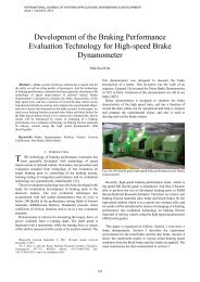
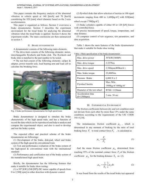
Fig. 2 brake performance dynamometer for high speed tra<strong>in</strong><br />
<strong>Brake</strong> dynamometer is designed to simulate <strong>the</strong> brake<br />
characteristic <strong>of</strong> <strong>the</strong> high speed tra<strong>in</strong>, and has a function <strong>of</strong><br />
record <strong>the</strong> data which can be reproduced and help to analyze and<br />
compare <strong>the</strong> experimental object, and also is used to develop<br />
and test <strong>the</strong> brake system.<br />
The expected effect and practical scheme <strong>of</strong> <strong>the</strong> brake<br />
dynamometer are follow<strong>in</strong>gs:<br />
(1) Development <strong>of</strong> <strong>the</strong> brake, disk-pad, wheel and brake<br />
system <strong>of</strong> <strong>the</strong> high-speed & conventional tra<strong>in</strong><br />
(2) Test and performance evaluation <strong>of</strong> <strong>the</strong> brake system <strong>of</strong><br />
<strong>the</strong> high-speed & conventional tra<strong>in</strong> with <strong>the</strong> <strong>in</strong>ternational<br />
standard<br />
(3) Performance and certification test <strong>of</strong> <strong>the</strong> brake system <strong>of</strong><br />
<strong>the</strong> manufactured high speed tra<strong>in</strong>.<br />
Briefly, <strong>the</strong> dynamometer has <strong>the</strong> follow<strong>in</strong>g features that<br />
make it suitable for brake show test<strong>in</strong>g:<br />
(1) a 397 [kW] (540 [HP]) DC motor capable <strong>of</strong> speeds from<br />
0 to 2,500[ rpm] <strong>in</strong> ei<strong>the</strong>r direction with dynamic control.<br />
2<br />
(2) flywheel disks that allow selection <strong>of</strong> <strong>in</strong>ertias <strong>in</strong> 100 equal<br />
<strong>in</strong>crements rang<strong>in</strong>g from 400 to 1,600[kg·㎡] with 820[mm]<br />
wheel except 1700[kg·㎡].<br />
(3) brake cyl<strong>in</strong>ders capable <strong>of</strong> ei<strong>the</strong>r 60 or 120 [kN] forces<br />
with controlled force.<br />
(4) precise measurement <strong>of</strong> speed, torque, temperature, and<br />
stop distance.<br />
(5) computer control <strong>of</strong> test sequence, test parameters, and<br />
data acquisition.<br />
Table 1 shows <strong>the</strong> ma<strong>in</strong> features <strong>of</strong> <strong>the</strong> brake dynamometer<br />
that make it suitable for brake shoe test<strong>in</strong>g<br />
Table 1 Ma<strong>in</strong> specification <strong>of</strong> <strong>the</strong> brake dynamometer<br />
Max. drive power 397kW(540HP)<br />
Max. drive torque 2,527Nm<br />
Max. drive speed 2,500rpm(400km/h )<br />
Max. brake torque 25,000Nm<br />
Pressure <strong>Brake</strong> 6,000 N x 2<br />
Flywheel Inertia<br />
Max./M<strong>in</strong>.<br />
1900kg·㎡/400kg·㎡<br />
Diameter <strong>of</strong> <strong>the</strong> test wheel Φ700∼1120mm<br />
Acceleration time<br />
(0~1500rpm)<br />
2 m<strong>in</strong>. 30 sec<br />
III. EXPERIMENTAL ENVIRONMENT<br />
The friction coefficients between dry and wet condition must<br />
not deviate from each o<strong>the</strong>r by more than 15% under <strong>the</strong> same<br />
conditions accord<strong>in</strong>g to <strong>the</strong> requirements <strong>of</strong> <strong>the</strong> UIC CODE<br />
541-4 [10].<br />
The <strong>in</strong>stantaneous friction coefficient µ a , which is<br />
determ<strong>in</strong>ed <strong>in</strong> any moment <strong>of</strong> brak<strong>in</strong>g by <strong>the</strong> ratio <strong>of</strong> total<br />
brak<strong>in</strong>g force F t to total contact force F b , is calculated as<br />
F<br />
t<br />
µ a =<br />
(1)<br />
Fb<br />
And <strong>the</strong> mean friction coefficient µ m determ<strong>in</strong>ed from<br />
reach<strong>in</strong>g 95% <strong>of</strong> <strong>the</strong> nom<strong>in</strong>al contact force Fb <strong>of</strong> <strong>the</strong> friction<br />
coefficient µ m for <strong>the</strong> brak<strong>in</strong>g distance S 2 as (2).<br />
2 1<br />
= ∫<br />
S<br />
µ m µ ads<br />
(2)<br />
S<br />
2<br />
It was found from <strong>the</strong> results <strong>of</strong> <strong>the</strong> tread brake test appeared<br />
0