Build Your Own 12 VDC Engine/Generator - Home Power Magazine
Build Your Own 12 VDC Engine/Generator - Home Power Magazine
Build Your Own 12 VDC Engine/Generator - Home Power Magazine

You also want an ePaper? Increase the reach of your titles
YUMPU automatically turns print PDFs into web optimized ePapers that Google loves.
<strong>Engine</strong>/<strong>Generator</strong>s<br />
<strong>Build</strong> <strong>Your</strong> <strong>Own</strong> <strong>12</strong> <strong>VDC</strong><br />
<strong>Engine</strong>/<strong>Generator</strong><br />
Richard Perez<br />
©1994 Richard Perez<br />
This small, easy to build,<br />
engine/alternator is the answer to<br />
a burning RE question. What do<br />
we do when the sun doesn’t shine, the<br />
wind doesn’t blow, and the creek dries<br />
up? This generator is a backup power<br />
source for times when our RE sources<br />
don’t meet our demands. It is optimized<br />
to do only one thing — properly<br />
recharge batteries on demand.<br />
<strong>Engine</strong>/<strong>Generator</strong> Overview<br />
I have built a dozen versions of this power plant in the<br />
last twenty years — three for myself and others for<br />
neighbors. Over the years the design has evolved, but<br />
the purpose remains the same — on-demand battery<br />
recharging and equalization. A version of this article<br />
first appeared in <strong>Home</strong> <strong>Power</strong> #2 — our most<br />
requested out-of-print back issue. Here is a revision of<br />
this information with an updated regulator design.<br />
In the early days (1982–1985), we used this type of<br />
engine setup as a prime mover. It supplied almost all of<br />
the energy for our system. We only had two PV<br />
modules at the time. As our PV/wind system grew, our<br />
dependence on the engine faded. Now we only use it<br />
during the depths of winter to meet those cloudy, allnight<br />
deadline sessions. From this experience we<br />
learned that while an engine is still a great energy<br />
back-up, it is a miserable prime mover for the system.<br />
These units are most effective if used less than 200<br />
hours yearly. Using the generator as the primary power<br />
input will yield 1,000 to 2,000 hours of engine operation<br />
yearly — a nightmare of expense, maintenance, and<br />
pollution.<br />
Source Capacity and Flexibility for Battery<br />
Equalization<br />
Every RE system should have at least one power<br />
source capable of recharging the batteries at between<br />
C/10 to C/20 rates of charge. For example, a battery<br />
pack of 700 Ampere-hours periodically needs to be<br />
recharged at a minimum of 35 Amperes (its C/20 rate).<br />
To figure the C/20 rate for your pack, simply divide its<br />
28 <strong>Home</strong> <strong>Power</strong> #42 • August / September 1994<br />
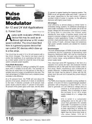
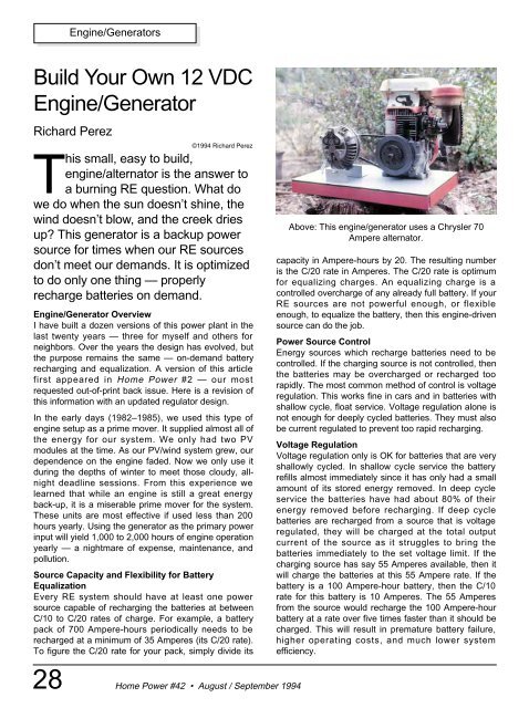
Above: This engine/generator uses a Chrysler 70<br />
Ampere alternator.<br />
capacity in Ampere-hours by 20. The resulting number<br />
is the C/20 rate in Amperes. The C/20 rate is optimum<br />
for equalizing charges. An equalizing charge is a<br />
controlled overcharge of any already full battery. If your<br />
RE sources are not powerful enough, or flexible<br />
enough, to equalize the battery, then this engine-driven<br />
source can do the job.<br />
<strong>Power</strong> Source Control<br />
Energy sources which recharge batteries need to be<br />
controlled. If the charging source is not controlled, then<br />
the batteries may be overcharged or recharged too<br />
rapidly. The most common method of control is voltage<br />
regulation. This works fine in cars and in batteries with<br />
shallow cycle, float service. Voltage regulation alone is<br />
not enough for deeply cycled batteries. They must also<br />
be current regulated to prevent too rapid recharging.<br />
Voltage Regulation<br />
Voltage regulation only is OK for batteries that are very<br />
shallowly cycled. In shallow cycle service the battery<br />
refills almost immediately since it has only had a small<br />
amount of its stored energy removed. In deep cycle<br />
service the batteries have had about 80% of their<br />
energy removed before recharging. If deep cycle<br />
batteries are recharged from a source that is voltage<br />
regulated, they will be charged at the total output<br />
current of the source as it struggles to bring the<br />
batteries immediately to the set voltage limit. If the<br />
charging source has say 55 Amperes available, then it<br />
will charge the batteries at this 55 Ampere rate. If the<br />
battery is a 100 Ampere-hour battery, then the C/10<br />
rate for this battery is 10 Amperes. The 55 Amperes<br />
from the source would recharge the 100 Ampere-hour<br />
battery at a rate over five times faster than it should be<br />
charged. This will result in premature battery failure,<br />
higher operating costs, and much lower system<br />
efficiency.
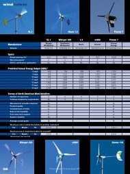
Above: The engine powering this generator is a Honda<br />
G40 model displacing 170 cc with a rated output of 4.5<br />
horsepower. This particular engine has outlived four<br />
alternators and now powers a 100 Ampere Chrysler<br />
alternator. I estimate that this engine has run over<br />
13,000 hours in the last fifteen years. It still has its<br />
original valves and piston rings.<br />
Right: Proper pulley alignment is essential for efficiency<br />
and long belt life. This particular generator would<br />
produce 60 Amperes of current for five hours while<br />
consuming about 3 ⁄ 4 of a gallon of gasoline.<br />
Constant Current<br />
Constant current charging means that the batteries are<br />
recharged at a fixed amperage rate until they are full.<br />
The voltage of the batteries is left unregulated until the<br />
batteries are full. The rate of charge is usually between<br />
C/10 and C/20. Constant current charging assures that<br />
the batteries are not charged too rapidly. Rates of<br />
charge greater than C/10 produce heat which can warp<br />
the thick plates of deep cycle batteries. Too rapid<br />
recharging wastes energy in heat and hydrolysis, and<br />
gradually ruins the batteries.<br />
<strong>Engine</strong>-driven <strong>Power</strong> Plants<br />
The engine-driven source has the distinct advantages<br />
of delivering large amounts of power when you need it.<br />
This is very different from wind and solar systems,<br />
where you have to take it when you can get it. Its major<br />
disadvantage is that it requires fuel and maintenance.<br />
<strong>Engine</strong>s do not usually suffer from being undersized. If<br />
the power source is capable of delivering between<br />
C/20 and C/10 rates of charge to the batteries, then the<br />
system is happy.<br />
Lawnmower <strong>Engine</strong>s and Car Alternators<br />
The idea here is to use a lawnmower engine (or any<br />
other small horizontal shaft engine) to drive an<br />
automotive alternator. The alternator puts out between<br />
35 and 200 Amperes (depending on its size) of <strong>12</strong> to<br />
<strong>Home</strong> <strong>Power</strong> #42 • August / September 1994<br />
<strong>Engine</strong>/<strong>Generator</strong>s<br />
16 Volt DC power to recharge the batteries. The first<br />
engine we used actually came from an old lawnmower<br />
we bought for $35. We got a 35 Ampere Delco<br />
alternator from a dead Chevy in the junkyard for $15.<br />
We bolted the entire works to a thick wood slab, and<br />
used an old oven heating element as a crude resistive<br />
field controller. The unit ran and charged our 350<br />
Ampere-hour battery for two years before the engine<br />
died.<br />
Type and Size of <strong>Engine</strong><br />
We’ve since tried many different combinations of<br />
engines and alternators. Small gas engines between 3<br />
and 8 horsepower work well. We found that the Honda<br />
small engines will run more than 5,000 hours without<br />
major work, Tecumseh engines about 800 hours, and<br />
Briggs & Stratton engines about 600 hours. The<br />
particular Honda G40 (170 cc, ≈4.5 hp) engine pictured<br />
here has run for over 13,000 hours with the same<br />
rings, bearings and valves. The Honda also has the<br />
advantage of a 100 hour oil change interval, compared<br />
with 25 hours for both the Tecumseh and the Briggs &<br />
Stratton. If you consider the operating life and<br />
operating cost of small engines, then the higher quality<br />
engines are much less expensive despite their higher<br />
initial cost. The engine’s size is determined by the size<br />
29
<strong>Engine</strong>/<strong>Generator</strong>s<br />
of the alternator. This assures a balance between<br />
system efficiency and cost. A 35 Ampere alternator can<br />
be driven by a 3 hp engine. A 100 Ampere alternator<br />
needs at least a 5 hp engine. For alternators between<br />
100 and 200 Amperes use the 8–<strong>12</strong> hp engine. See<br />
Access at the end of this article for a source of small<br />
gasoline engines.<br />
Type and Size of Alternator<br />
Just about any automotive alternator will work in these<br />
systems. What really counts is the size of the<br />
alternator. Its current output (amperage rating) should<br />
be sized to match the capacity of the battery pack. The<br />
more capacity the battery pack has, the bigger the<br />
alternator must be. The alternator must be able to<br />
deliver at least a C/20 rate of charge to the batteries.<br />
We have had good results with 35 Ampere Delco<br />
alternators for battery packs under 700 Ampere-hours.<br />
Batteries up to 1,400 Ampere-hours are fed with the<br />
100 Ampere Chrysler alternators. Packs larger than<br />
1,400 Ampere-hours should have a 200 Ampere rated<br />
alternator. The higher amperage alternators are<br />
measurably more efficient than the smaller ones.<br />
The higher amperage alternators are more difficult to<br />
find. Try your local auto electric shops, they may have<br />
a source for these high amp jewels. Regular alternators<br />
up to 70 Amperes are usually available from junkyards<br />
at less than $20. Alternator rebuilders can provide<br />
rebuilt units (new bearings and brushes) from $40 to<br />
$150. These alternators are a good investment. They<br />
are designed to run under the hood of a hot car on a<br />
summer day. In the type of service we give them, they<br />
run cool and last a very long time. I’ve seen these<br />
alternators last over 10 years with just the replacement<br />
of bearings and brushes.<br />
The more modern alternators contain their voltage<br />
regulators within the alternator’s case. These internal<br />
regulators need to be disabled and/or removed before<br />
these alternators are useful in this system. If you can’t<br />
do this yourself, then take the alternator to an alternator<br />
shop for help. Some alternators have what is known as<br />
an “isolated field”. These need to have one field<br />
connection grounded to the alternator’s case and<br />
simply feed positive energy to the other field<br />
connection. The older Delco types are very simple and<br />
straightforward to use. They require no modification.<br />
Every alternator is a little different, so if you’re not sure<br />
what you have, then go to the library and look it up in<br />
an automotive manual.<br />
Getting it all together — Assembly<br />
We originally bolted both the alternator and the engine<br />
to a wooden slab about 16 inches by 24 inches and 4<br />
inches thick. Be very careful with engine and alternator<br />
30 <strong>Home</strong> <strong>Power</strong> #42 • August / September 1994<br />
pulley alignment. If the engine pulley and the alternator<br />
pulley are not properly aligned (in the same plane),<br />
then the unit will wear belts out very rapidly. These<br />
engine/alternator combos work best on heavy metal<br />
bases. There is a lot of vibration and the wooden slabs<br />
give up after a few years. Either add a sheet of 1/4 inch<br />
to 3/8 inch thick steel between the wood and the<br />
engine/alternator, or make the base completely out of<br />
metal. A local welding shop made us a base out of 3/8<br />
inch thick steel plate with a welded one inch by two<br />
inch steel square tubing perimeter for $50. You can<br />
see it in the photograph. If you can weld, the materials<br />
cost about $18. Use heavy bolts with lock washers to<br />
secure everything to the base.<br />
We coupled the alternator to the engine with an “A”<br />
sized Vee belt. Keep the belt length to a minimum by<br />
mounting the engine and alternator close together. We<br />
use belts between 28 and 33 inches in total length. The<br />
stock pulley on the alternator works well. The best<br />
sized engine pulley is between five and six inches in<br />
diameter. This pulley ratio gears up the alternator for<br />
better efficiency while allowing the engine to run about<br />
2,200 rpm. We have had very poor results with the<br />
lightweight cast aluminum pulleys or any pulley using<br />
set screws. These light pulleys were not up to the high<br />
vibration job and broke frequently. We’re now using<br />
cast and machined iron pulleys (such as the Woods<br />
brand SDS pulleys) that work very well and are<br />
extremely rugged. These are available from power<br />
transmission product stores and cost about $40.<br />
Be sure to get the alternator turning in the right<br />
direction. Electrically it makes no difference, but the<br />
alternator’s fan is designed to suck air from the back of<br />
the alternator and to exhaust this air in front around the<br />
pulley. If the alternator’s fan is running backwards then<br />
the alternator will overheat when heavily loaded.<br />
Use large wire to hook up the output of the alternator.<br />
Something between 6 gauge and 0 gauge is fine,<br />
depending on the length of the runs. Locate the<br />
engine/alternator as close as possible to the batteries.<br />
This keeps power loss in the wiring to a minimum.<br />
Control Systems<br />
The very first engine-driven charger we built worked<br />
fine, but we had problems controlling it. We were using<br />
a standard car voltage regulator. It wanted to charge<br />
the batteries far too quickly and the large load often<br />
stalled the engine. We experimented with many forms<br />
of control and found two which work well.<br />
Alternator controls work by limiting the amount of<br />
power supplied to the alternator’s rotating magnetic<br />
field. All alternator control starts with controlling this<br />
magnetic field’s energy.
Car Voltage Regulators<br />
Car voltage regulators will not work well in deep cycle<br />
applications. The regulator makes its decisions based<br />
only on the system’s voltage. This is fine with the<br />
average car battery which is cycled to less than 1% of<br />
its capacity before being refilled. However, the deep<br />
cycle battery is almost empty when it is recharged. The<br />
car voltage regulator attempts to instantly bring the<br />
system’s voltage to 14–15 Volts. A <strong>12</strong> Volt deep cycle<br />
lead-acid battery will not reach a voltage of 14 Volts<br />
until it is almost filled. The net result is that the car<br />
regulator dumps the entire output of the alternator into<br />
the batteries until they are full. This is almost always<br />
too much energy too fast for a fully discharged battery.<br />
To compound the problem, the car regulator’s voltage<br />
limit is set too low for deep cycle service. This low<br />
voltage limit means that the batteries are charged too<br />
slowly when they are almost full, resulting in many<br />
extra hours of generator operation to totally fill the<br />
battery pack. Since the car regulator is set at about 14<br />
Volts, we are unable to raise the system voltage up to<br />
over 16 Volts for the essential equalizing charges.<br />
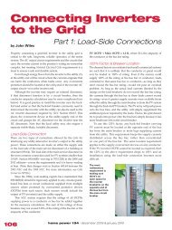
Resistive Field Controller<br />
The simplest control for the alternator is resistance to<br />
limit the power to the alternator’s field. The idea is<br />
simple: insert resistance between the battery’s positive<br />
SPST<br />
5 A.<br />
<strong>Power</strong><br />
input<br />
11 to 16<br />
<strong>VDC</strong><br />
1<br />
kΩ<br />
.1<br />
μf<br />
10<br />
μf<br />
3<br />
kΩ<br />
1<br />
kΩ<br />
3<br />
kΩ<br />
4<br />
5<br />
6<br />
<strong>12</strong> 11<br />
LM<br />
723<br />
2.2<br />
kΩ<br />
Field Controller version 8.3 — Parts Notes<br />
7<br />
9<br />
4.7<br />
kΩ<br />
50<br />
kΩ<br />
4.7<br />
kΩ<br />
D1<br />
.001<br />
μf<br />
Integrated Circuits<br />
LM723 Voltage Regulator, in 14 pin DIP<br />
NE555 Timer, in 8 pin DIP<br />
Transistors<br />
Q1- 2N2222A or eqiv. NPN<br />
Q2- MJE 2955, or any PNP with Ic>5 Amps., heatsunk<br />
D1<br />
.01<br />
μf<br />
Automotive<br />
A lt e r n a t o r<br />
7<br />
2<br />
8<br />
NE<br />
555<br />
6<br />
4<br />
1 5<br />
switch<br />
<strong>Home</strong> <strong>Power</strong> #42 • August / September 1994<br />
3<br />
.01<br />
μf<br />
1 kΩ<br />
1<br />
kΩ<br />
<strong>Engine</strong>/<strong>Generator</strong>s<br />
25 Ohm<br />
rheostat<br />
100Ω<br />
10 W.<br />
Q2<br />
Q1<br />
Amps<br />
Volts<br />
A resistive field controller.<br />
Electronic Field Controller version 8.3<br />
.1<br />
μf<br />
D2<br />
1<br />
kΩ<br />
<strong>12</strong><br />
Volt<br />
Battery<br />
pole and the alternator’s field. This controls the<br />
intensity of the alternator’s electromagnetic field and<br />
thereby its power output. Resistance of 2 to 25 Ohms<br />
works well. Adjust the resistance until the charge rate<br />
is between C/20 and C/10. The less resistance in the<br />
field line, the higher the amperage output of the<br />
alternator. Originally, we used a nichrome wire heating<br />
element from an old electric stove. We selected more<br />
or less wire (hence more or less resistance) with an<br />
alligator clip lead. It worked fine. A better resistor is a 0<br />
to 25 Ohm rheostat (adjustable power resistor) rated at<br />
least 25 Watts. This allows smooth adjustment of the<br />
alternator’s output. The illustration above shows the<br />
wiring hookup for a resistive field controller. The switch<br />
shown in this circuit needs to handle about 5 Amperes<br />
and prevents energizing of the field when the charger<br />
is not in use. See Access for a rheostat source.<br />
Output to<br />
alternator<br />
field<br />
Diodes<br />
D1- 1N914 or equivalent<br />
D2- 1N<strong>12</strong>02A, or any 3+ Ampere diode, heatsunk<br />
All resistors 1/4 Watt & 5% unless otherwise noted<br />
All capacitors are 25 Volt rated<br />
All commercial rights reserved. Any commercial use of this circuit is prohibited<br />
without written permission. <strong>Home</strong>building of single devices by the end user is<br />
approved and encouraged without written permission.<br />
31
<strong>Engine</strong>/<strong>Generator</strong>s<br />
Using resistive field control only regulates current. The<br />
resistive circuit does not provide any form of voltage<br />
regulation. When the batteries are full the system<br />
voltage can get high, over 16 Volts. Voltage this high<br />
can damage <strong>12</strong> <strong>VDC</strong> appliances. The highest voltage<br />
for most <strong>12</strong> Volt equipment is around 15 Volts. If you<br />
are using resistive field control, be sure to monitor the<br />
system’s voltage and reduce the current output of the<br />
alternator to keep the system voltage under 15 Volts<br />
when appliances are being used.<br />
Electronic Field Controller<br />
We eventually solved the problem of control by<br />
designing electronic field controllers that regulate both<br />
the amperage and the voltage of the alternator. With<br />
this electronic field control, we simply set the desired<br />
charge rate, and set the system’s voltage ceiling. The<br />
battery is recharged at a constant rate until it is full.<br />
When the batteries are full, the voltage limit<br />
predominates and the system is voltage regulated,<br />
thereby protecting the batteries from overcharging. And<br />
also protecting all electrical equipment on line. The<br />
amperage output is adjustable from 0 to the full rated<br />
output of the alternator. The voltage limit is adjustable<br />
from 13.5 Volts to 16.5 Volts.<br />
For the intrepid electronic builder, this electronic field<br />
controller’s schematic is included on page 31. It uses<br />
off-the-shelf parts available at Radio Shack or any<br />
electronics supply store.<br />
<strong>Engine</strong>s for Equalizing Charges<br />
This engine-driven source is a good type to use for the<br />
equalizing charges and whenever the RE sources are<br />
not keeping up with the system’s energy consumption.<br />
Its voltage output is capable of being adjusted to over<br />
16 Volts in order to accomplish the equalizing charge.<br />
The engine-driven source is capable of delivering a<br />
C/20 rate of charge for the at least five continuous<br />
hours necessary for battery equalization. Remember<br />
the batteries must already be full before the equalizing<br />
charge is started.<br />
Access<br />
Author: Richard Perez, c/o <strong>Home</strong> <strong>Power</strong>, PO Box 520,<br />
Ashland, OR 97520 • 916-475-3179<br />
<strong>Engine</strong>s: Northern Hydraulics, PO Box <strong>12</strong>19,<br />
Burnsville, MN 55337 • 800-533-5545 • 6<strong>12</strong>-894-9510<br />
Rheostats and surplus meters: Fair Radio Sales, PO<br />
Box 1105, Lima, OH 45802 • 419-223-2196<br />
32 <strong>Home</strong> <strong>Power</strong> #42 • August / September 1994