Pulse Width Modulator - Home Power Magazine
Pulse Width Modulator - Home Power Magazine
Pulse Width Modulator - Home Power Magazine

You also want an ePaper? Increase the reach of your titles
YUMPU automatically turns print PDFs into web optimized ePapers that Google loves.
<strong>Home</strong>brew<br />
<strong>Pulse</strong><br />
<strong>Width</strong><br />
<strong>Modulator</strong><br />
<strong>Home</strong>brew<br />
for 12 and 24 Volt Applications<br />
G. Forrest Cook ©2000 G. Forrest Cook<br />
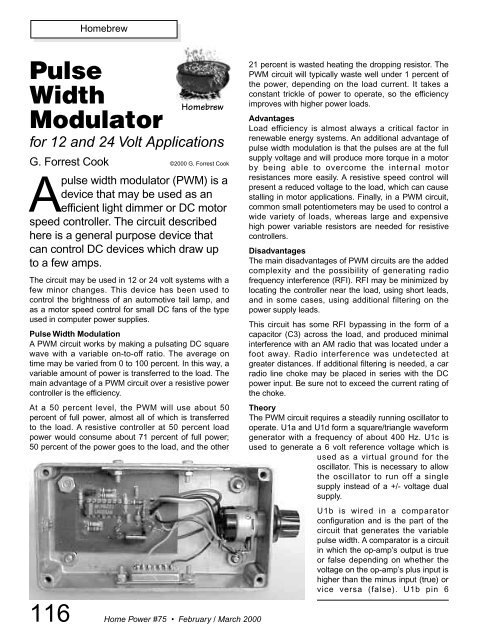
Apulse width modulator (PWM) is a<br />
device that may be used as an<br />
efficient light dimmer or DC motor<br />
speed controller. The circuit described<br />
here is a general purpose device that<br />
can control DC devices which draw up<br />
to a few amps.<br />
The circuit may be used in 12 or 24 volt systems with a<br />
few minor changes. This device has been used to<br />
control the brightness of an automotive tail lamp, and<br />
as a motor speed control for small DC fans of the type<br />
used in computer power supplies.<br />
<strong>Pulse</strong> <strong>Width</strong> Modulation<br />
A PWM circuit works by making a pulsating DC square<br />
wave with a variable on-to-off ratio. The average on<br />
time may be varied from 0 to 100 percent. In this way, a<br />
variable amount of power is transferred to the load. The<br />
main advantage of a PWM circuit over a resistive power<br />
controller is the efficiency.<br />
At a 50 percent level, the PWM will use about 50<br />
percent of full power, almost all of which is transferred<br />
to the load. A resistive controller at 50 percent load<br />
power would consume about 71 percent of full power;<br />
50 percent of the power goes to the load, and the other<br />
21 percent is wasted heating the dropping resistor. The<br />
PWM circuit will typically waste well under 1 percent of<br />
the power, depending on the load current. It takes a<br />
constant trickle of power to operate, so the efficiency<br />
improves with higher power loads.<br />
Advantages<br />
Load efficiency is almost always a critical factor in<br />
renewable energy systems. An additional advantage of<br />
pulse width modulation is that the pulses are at the full<br />
supply voltage and will produce more torque in a motor<br />
by being able to overcome the internal motor<br />
resistances more easily. A resistive speed control will<br />
present a reduced voltage to the load, which can cause<br />
stalling in motor applications. Finally, in a PWM circuit,<br />
common small potentiometers may be used to control a<br />
wide variety of loads, whereas large and expensive<br />
high power variable resistors are needed for resistive<br />
controllers.<br />
Disadvantages<br />
The main disadvantages of PWM circuits are the added<br />
complexity and the possibility of generating radio<br />
frequency interference (RFI). RFI may be minimized by<br />
locating the controller near the load, using short leads,<br />
and in some cases, using additional filtering on the<br />
power supply leads.<br />
This circuit has some RFI bypassing in the form of a<br />
capacitor (C3) across the load, and produced minimal<br />
interference with an AM radio that was located under a<br />
foot away. Radio interference was undetected at<br />
greater distances. If additional filtering is needed, a car<br />
radio line choke may be placed in series with the DC<br />
power input. Be sure not to exceed the current rating of<br />
the choke.<br />
Theory<br />
The PWM circuit requires a steadily running oscillator to<br />
operate. U1a and U1d form a square/triangle waveform<br />
generator with a frequency of about 400 Hz. U1c is<br />
used to generate a 6 volt reference voltage which is<br />
used as a virtual ground for the<br />
oscillator. This is necessary to allow<br />
the oscillator to run off a single<br />
supply instead of a +/- voltage dual<br />
supply.<br />
U1b is wired in a comparator<br />
configuration and is the part of the<br />
circuit that generates the variable<br />
pulse width. A comparator is a circuit<br />
in which the op-amp’s output is true<br />
or false depending on whether the<br />
voltage on the op-amp’s plus input is<br />
higher than the minus input (true) or<br />
vice versa (false). U1b pin 6<br />
116 <strong>Home</strong> <strong>Power</strong> #75 • February / March 2000
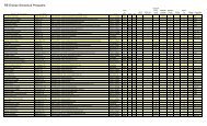
<strong>Home</strong>brew<br />
<strong>Pulse</strong> <strong>Width</strong> <strong>Modulator</strong> Specifications<br />
Item<br />
PWM frequency<br />
Maximum current with IRF521 FET<br />
Maximum current with IRFZ34N FET<br />
PWM circuit current<br />
Operating voltage<br />
receives a variable voltage from the R6, VR1, R7<br />
voltage ladder. This is compared to the triangle<br />
waveform from U1d pin 14. When the waveform is<br />
above the pin 6 voltage, U1 produces a high output.<br />
Conversely, when the waveform is below the pin 6<br />
voltage, U1 produces a low output. By varying the pin 6<br />
voltage, the on/off points are moved up and down the<br />
triangle wave, producing a variable pulse width.<br />
Resistors R6 and R7 are used to set the end points of<br />
the VR1 control. The values shown allow the control to<br />
have a full on and a full off setting within the travel of<br />
the potentiometer. These part values may be varied to<br />
change the behavior of the potentiometer.<br />
Q1 is the power switch. It receives the modulated pulse<br />
width voltage on the gate terminal and switches the<br />
load current on and off through the source-drain current<br />
path. When Q1 is on, it provides a ground path for the<br />
load. When Q1 is off, the load’s ground is floating. Care<br />
should be taken to insure that the load terminals are not<br />
grounded or a short will occur. The load will have the<br />
supply voltage on the positive side at all times.<br />
The controller with a DC muffin fan.<br />
LED1 is optional and gives a<br />
variable brightness response<br />
to the pulse width. Capacitor<br />
C3 smooths out the<br />
switching waveform and<br />
removes some RFI. Diode<br />
D1 is a flywheel diode that<br />
shorts out the reverse<br />
voltage kick from inductive<br />
motor loads. In the 24 volt mode, regulator U2 converts<br />
the 24 volt supply to 12 volts for running the PWM<br />
circuit. Q1 switches the 24 volt load to ground, as it<br />
does for the 12 volt load. See the schematic for<br />
instructions on wiring the circuit for 12 or 24 volts.<br />
At the 1 amp current level, no heat sink is needed on<br />
Q1. However, if you will be switching more current, a<br />
large heat sink is mandatory. Q1 may be replaced with<br />
a higher current device such as an IRFZ34N. All of the<br />
current handling devices, switch S1, fuse F1, and the<br />
wiring between the FET, power supply, and load should<br />
be able to handle the maximum load current.<br />
To prevent shortening the life of the FET, it is advisable<br />
to run the circuit below the maximum rated current.<br />
Eighty percent of maximum is a safe range to work<br />
with. Inductive loads such as motors have huge peak<br />
current ratings, and exceeding the ratings of the FET<br />
will guarantee part failure. Take into account the<br />
maximum current for the motor when it is stalled. High<br />
power motor controllers require extra clamping circuitry<br />
for reducing high voltage spikes. This is usually done<br />
with zener diodes across the FET D-S terminals.<br />
Information on such circuitry is beyond the scope of this<br />
article—consult the data sheets from the FET<br />
manufacturer (International Rectifier Corp,<br />
www.irf.com).<br />
Specification<br />
400 Hz<br />
9 A continuous, 27 A peak<br />
26 A continuous, 100 A peak<br />
1.5 mA at 12 V with no LED and no load<br />
12 or 24 V, depending on the configuration<br />
PWM Parts List<br />
U1<br />
LM324N quad op-amp<br />
U2<br />
78L12 12 V regulator<br />
Q1<br />
IRF521 N channel MOSFET<br />
D1<br />
1N4004 silicon diode<br />
LED1 Red LED (any kind should work)<br />
C1 0.01 µF ceramic disc capacitor, 25 V<br />
C2–C5 0.1 µF ceramic disc capacitor, 50 V<br />
R1–R4<br />
100 K 1/4 W resistor<br />
R5<br />
47 K 1/4 W resistor<br />
R6–R7<br />
3.9 K 1/4 W resistor<br />
R8<br />
2.7 K 1/4 W resistor<br />
VR1<br />
10 K linear potentiometer<br />
F1<br />
3 A, 28 VDC fast-blow fuse<br />
S1<br />
toggle switch, 5 A<br />
<strong>Home</strong> <strong>Power</strong> #75 • February / March 2000<br />
117
<strong>Home</strong>brew<br />
PWM Schematic<br />
Construction<br />
The prototype for this circuit was constructed on a<br />
regular IC proto board, with parts and wires stuck into<br />
the proto board holes. One version of the finished<br />
circuit was used to make a variable speed DC fan. The<br />
fan was mounted on top of a small metal box and the<br />
PWM circuit was contained inside the box.<br />
I built a simple circuit board using a free circuit<br />
board CAD program, PCB, which runs on<br />
the Linux operating system. The circuit<br />
board image was printed with a<br />
PostScript laser printer onto a mask<br />
transfer product called Techniks<br />
Press-n-Peel blue film. The<br />
printed film is then ironed on<br />
to a cleaned piece of single<br />
sided copper-clad board.<br />
PWM<br />
Circuit Board<br />
The circuit board is etched<br />
with ferric chloride solution.<br />
A board pattern is shown at<br />
right. This may be<br />
photocopied onto a piece of<br />
Press-n-Peel blue film. The<br />
circuit board and parts layout<br />
are available for download<br />
from www.homepower.com.<br />
Holes are drilled with a fine<br />
gauge drill bit, parts are soldered<br />
in, and the board is wired to the<br />
power and load. This technique is great<br />
for producing working boards in a short time,<br />
but is not suitable for large numbers of boards.<br />
118 <strong>Home</strong> <strong>Power</strong> #75 • February / March 2000<br />
PWM Component Locations<br />
F1<br />
Q1<br />
R5<br />
LED1<br />
Alternately, the “dead-bug”<br />
construction method may be used.<br />
The name “dead-bug” comes from<br />
the appearance of the circuit board,<br />
with chips and parts strung together<br />
at random angles. This involves<br />
taking a piece of blank copper PC<br />
board, gluing a wire-wrap IC socket<br />
to the board with five minute epoxy,<br />
then soldering all of the parts to the<br />
wire wrap pins. Grounded pins can<br />
be soldered directly to the copper<br />
board. No alignment should be<br />
necessary with this circuit.<br />
The PWM component locations<br />
pictorial is shown from the parts<br />
side—solder on the other side of the<br />
board. The circuit board is for the<br />
12 volt version of the circuit. It may<br />
be used for 24 volts by wiring an<br />
external 12 V regulator for the +12 V<br />
D1<br />
R3<br />
Jumper<br />
C3<br />
R4<br />
U1<br />
CN1<br />
R8<br />
R6<br />
R2<br />
C1<br />
R1<br />
R7<br />
C2
<strong>Home</strong>brew<br />
supply, and moving the parts at the DC load + terminal<br />
to 24 V power.<br />
Circuit board connections for CN1 (pin 1 is marked with<br />
a square):<br />
1 VR1-low<br />
2 VR1-high<br />
3 +12 V power from fused line<br />
4 VR1-center<br />
5 Load +<br />
6 Spare ground<br />
7 Load -<br />
8 Ground return for 12 V power<br />
Use<br />
This circuit will work as a DC lamp dimmer, small motor<br />
controller, and even as a small heater controller. It<br />
would make a great speed control for a solar-powered<br />
electric train. I have not tried the circuit with larger<br />
motors. In theory, it should work in applications such as<br />
a bicycle motor drive system. If you experiment with<br />
this, be sure to include an easily accessible emergency<br />
power disconnect switch in case the FET shorts on.<br />
Keep in mind that the pulse current through DC motors<br />
will be many times the average motor current rating.<br />
The FET will be destroyed if its specifications cannot<br />
handle the full pulse current. FETs may be wired in<br />
parallel to increase their current.<br />
Wire the circuit for 12 volts or 24 volts as per the<br />
schematic, connect the battery to the input terminals,<br />
and connect the load to the output terminals. Be sure<br />
not to ground either of the output terminals, or anything<br />
connected to the output terminals, such as a motor<br />
case. Turn the potentiometer knob back and forth; the<br />
load should show variable speed or light.<br />
Access<br />
Author: G. Forrest Cook, WB0RIO, 2910 Carnegie Dr.,<br />
Boulder, CO 80303 • cook@eklektix.com<br />
www.eklektix.com/gfc/ • PC Board PostScript files:<br />
www.eklektix.com/gfc/elect/solarcirc/pwm1/index.html<br />
Parts:<br />
Jameco, 1355 Shoreway Rd., Belmont, CA 94002<br />
800-831-4242 or 650-592-8097<br />
Fax: 800-237-6948 or 650-592-2503<br />
info@jameco.com • www.jameco.com<br />
Digi-Key, PO Box 677, Thief River Falls,<br />
MN 56701-0677 • 800-DIGIKEY or 218-681-6674<br />
Fax: 218-681-3380 • sales@digikey.com<br />
www.digikey.com<br />
PCB Software • ftp://ftp.uni-ulm.de/pub/pcb/mirror<br />
Techniks, Inc., PO Box 463, Ringoes, NJ 08551<br />
908-788-8249 • Fax: 908-788-8837 • www.techniks.com<br />
CHANGE THE WORLD<br />
Affordable On-Grid Solar Electricity<br />
• ASE module with integrated 250-watt<br />
Advanced Energy utility-tie inverter<br />
• Simple installation - no dc wiring,<br />
just connect to your load center<br />
• Affordable - start with one, expand<br />
in the future without rewiring<br />
• PC monitoring card option<br />
• UL listed,American made<br />
With our partner, Advanced Energy Systems, we offer you the<br />
tools to change the world, wherever you live, on-grid or off.Visit<br />
us at www.solarvt.com or www.advancedenergy.com<br />
SOLAR WORKS, INC.<br />
64 Main Street, Montpelier, VT 05602<br />
Tel: (802) 223-7804 Fax: (802) 223-8980<br />
RENEWABLE ENERGY SOLUTIONS<br />
• Wind <strong>Power</strong><br />
• Microhydro<br />
• Solar<br />
• Independent<br />
<strong>Power</strong><br />
Systems<br />
Pedal<br />
Your Way<br />
to Energy<br />
Independence!<br />
WINDSTREAM<br />
POWER SYSTEMS INC.<br />
PO Box 1604 HP, Burlington, VT 05402<br />
25 Years in Business<br />
HUMAN<br />
POWERED<br />
GENERATOR<br />
Easy to Use<br />
Economical<br />
Dependable<br />
Fun!<br />
TEL 802-658-0075<br />
FAX 802-658-1098<br />
e-mail:<br />
info@windstreampower.com<br />
website:<br />
www.windstreampower.com<br />
<strong>Home</strong> <strong>Power</strong> #75 • February / March 2000<br />
119