Connecting Inverters to the Grid - Home Power Magazine
Connecting Inverters to the Grid - Home Power Magazine
Connecting Inverters to the Grid - Home Power Magazine

Create successful ePaper yourself
Turn your PDF publications into a flip-book with our unique Google optimized e-Paper software.
<strong>Connecting</strong> <strong>Inverters</strong><br />
<strong>to</strong> <strong>the</strong> <strong>Grid</strong><br />
by John Wiles<br />
Properly connecting a grid-tied inverter <strong>to</strong> <strong>the</strong> utility grid is<br />
critical <strong>to</strong> <strong>the</strong> safe, long-term, reliable operation of <strong>the</strong> entire<br />
system. The AC output circuit requirements and <strong>the</strong> circuits that<br />
carry <strong>the</strong> inverter current in <strong>the</strong> premise’s wiring are somewhat<br />
complex, but meeting National Electrical Code requirements is a<br />
must <strong>to</strong> ensure a safe and durable system.<br />
Even though energy flows from <strong>the</strong> inverter <strong>to</strong> <strong>the</strong> utility, it’s<br />
at <strong>the</strong> utility end of this circuit where <strong>the</strong> currents originate that<br />
can harm <strong>the</strong> conduc<strong>to</strong>rs when faults occur. Any overcurrent<br />
protection should be located at <strong>the</strong> utility end of <strong>the</strong> inverter AC<br />
output circuit—not at <strong>the</strong> inverter end.<br />
Although <strong>the</strong> inverter may require an external disconnect,<br />
if that disconnect function is by a circuit breaker, <strong>the</strong>n <strong>the</strong><br />
conduc<strong>to</strong>r ampacity calculations may be more complicated (see<br />
below). It is good practice <strong>to</strong> install <strong>the</strong> inverter near <strong>the</strong> backfed<br />
load center so that <strong>the</strong> back-fed breaker commonly used <strong>to</strong><br />
interconnect <strong>the</strong> inverter with <strong>the</strong> utility can also be used as <strong>the</strong><br />
AC inverter disconnect required by NEC Section 690.15. This<br />
places <strong>the</strong> overcurrent device at <strong>the</strong> utility-supply end of <strong>the</strong><br />
circuit and groups <strong>the</strong> AC disconnect for <strong>the</strong> inverter near <strong>the</strong><br />
DC disconnect. Note that <strong>the</strong> local utility may also require a<br />
separate visible-blade, lockable disconnect.<br />
Load-Side Connection<br />
There are two types of connections allowed by <strong>the</strong> Code for<br />
interfacing any utility-interactive inverter’s output <strong>to</strong> <strong>the</strong> utility<br />
power. These connections are made on ei<strong>the</strong>r <strong>the</strong> supply side<br />
or <strong>the</strong> load side of <strong>the</strong> main service disconnect of a building or<br />
structure (690.64). The load side of <strong>the</strong> main service disconnect is<br />
<strong>the</strong> most common connection used for PV systems smaller than<br />
10 kW. Section 690.64(B)—moving <strong>to</strong> 705.12(D) in <strong>the</strong> 2008 and<br />
2011 editions—covers <strong>the</strong> requirements and it is heavy reading<br />
at best. (Note that changes exist in Section 690.64 between <strong>the</strong><br />
2005 NEC and <strong>the</strong> 2008 NEC. For more information, see Code<br />
Corner in HP126.)<br />
Since <strong>the</strong> 1980s, code-making experts have maintained that<br />
690.64(B)(2) should be rigorously applied <strong>to</strong> any circuits (panelboard<br />
bus bars or circuit conduc<strong>to</strong>rs) supplied from multiple<br />
sources where protected by overcurrent protective devices<br />
(OCPDs) from each source. Such sources would include <strong>the</strong><br />
output of PV inverter(s) and <strong>the</strong> utility supply.<br />
This NEC section requires that <strong>the</strong> ratings of all OCPDs<br />
supplying power <strong>to</strong> a conduc<strong>to</strong>r or bus bar be added <strong>to</strong>ge<strong>the</strong>r<br />
for <strong>the</strong> necessary calculations. The sum of <strong>the</strong> ratings of those<br />
breakers may not exceed 120% of <strong>the</strong> rating of <strong>the</strong> bus bar or <strong>the</strong><br />
ampacity of <strong>the</strong> conduc<strong>to</strong>r:<br />
106<br />
Part 1: Load-Side Connections<br />
home power 134 / december 2009 & january 2010<br />
PV OCPD + Main OCPD ≤ 1.2 R, where R is <strong>the</strong> ampacity of<br />
<strong>the</strong> conduc<strong>to</strong>r or <strong>the</strong> bus bar rating.<br />
120% Fac<strong>to</strong>r & Breaker Location<br />
The demand fac<strong>to</strong>rs on residential and small commercial systems<br />
are such that it is unlikely that <strong>the</strong> conduc<strong>to</strong>r or panel would<br />
ever be loaded <strong>to</strong> 100% of rating. Even if <strong>the</strong> sources could<br />
supply 120% of <strong>the</strong> rating of <strong>the</strong> bus bar or conduc<strong>to</strong>r, loads<br />
connected <strong>to</strong> that same bus bar or conduc<strong>to</strong>r—so long as <strong>the</strong>y<br />
don’t exceed <strong>the</strong> bus bar rating—would not pose an overload<br />
problem. As long as <strong>the</strong> actual load currents (limited by <strong>the</strong><br />
ratings on <strong>the</strong> load breakers) do not exceed <strong>the</strong> bus bar rating,<br />
<strong>the</strong> currents through <strong>the</strong> bus bar <strong>to</strong> <strong>the</strong>se loads cannot exceed<br />
its rating—even if greater supply currents were available (from<br />
ei<strong>the</strong>r <strong>the</strong> utility through <strong>the</strong> main breaker or from <strong>the</strong> PV system<br />
through <strong>the</strong> back-fed PV breaker). The PV array will push power<br />
on<strong>to</strong> <strong>the</strong> bus bars, and <strong>the</strong> utility will simply supplement <strong>the</strong><br />
additional power required by <strong>the</strong> loads. That is, <strong>the</strong> grid doesn’t<br />
try <strong>to</strong> push extra power on<strong>to</strong> <strong>the</strong> bus bars simply because it has<br />
more headroom left on <strong>the</strong> circuit breaker.<br />
To use this 120% fac<strong>to</strong>r, any back-fed breaker carrying<br />
PV current must be located at <strong>the</strong> opposite end of <strong>the</strong> bus<br />
bar from <strong>the</strong> main breaker or main lugs supplying current<br />
from <strong>the</strong> utility. This requirement keeps <strong>the</strong> supply currents<br />
distributed across <strong>the</strong> bus bar, ra<strong>the</strong>r than concentrated<br />
on one part of <strong>the</strong> bus bar. The same location requirement<br />
applies <strong>to</strong> <strong>the</strong> supply overcurrent devices on any conduc<strong>to</strong>r.<br />
If <strong>the</strong> PV inverter OCPD cannot be located as required, <strong>the</strong>n<br />
<strong>the</strong> 120% in <strong>the</strong> above requirement drops <strong>to</strong> 100% and an<br />
installation using <strong>the</strong> load-side connection becomes more<br />
difficult.<br />
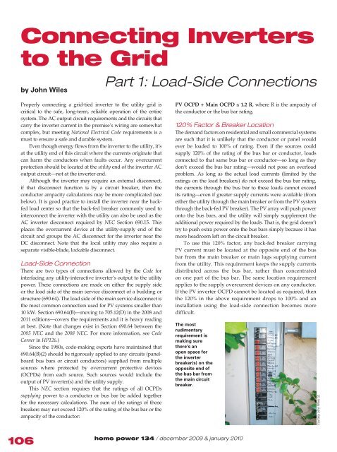
The most<br />
rudimentary<br />
requirement is<br />
making sure<br />
<strong>the</strong>re’s an<br />
open space for<br />
<strong>the</strong> inverter<br />
breaker(s) on <strong>the</strong><br />
opposite end of<br />
<strong>the</strong> bus bar from<br />
<strong>the</strong> main circuit<br />
breaker.<br />
Courtesy John Wiles (2)
The Article 240 tap rules do not apply <strong>to</strong> <strong>the</strong>se inverter<br />
connections since <strong>the</strong>y were developed only for circuits with<br />
one source. The OCPD for <strong>the</strong> inverter output circuit should<br />
be located, as mentioned above, at <strong>the</strong> point nearest where <strong>the</strong><br />
utility currents could feed <strong>the</strong> circuit in <strong>the</strong> event of a fault (i.e.,<br />
in <strong>the</strong> main service panel or inverter AC combining panel, ra<strong>the</strong>r<br />
than at <strong>the</strong> inverter). It is a common mistake <strong>to</strong> apply <strong>the</strong> Article<br />
240 tap rules incorrectly and locate <strong>the</strong> OCPD at some point<br />
away from <strong>the</strong> tap point. This may create conduc<strong>to</strong>r protection<br />
issues when multiple sources are involved.<br />
Example Calculations<br />
1. A dwelling has a 125-amp service panel (bus bar rating) with<br />
a 100 A main breaker at <strong>the</strong> <strong>to</strong>p. How large can <strong>the</strong> back-fed PV<br />
breaker be that must be located at <strong>the</strong> bot<strong>to</strong>m of <strong>the</strong> panel?<br />
PV OCPD + Main OCPD ≤ 120% of service-panel rating<br />
120% of panel rating = 1.2 x 125 A = 150 A<br />
PV OCPD + 100 A ≤ 150 A<br />
PV OCPD ≤ 150 A – 100 A or 50 A<br />
The PV OCPD can be up <strong>to</strong> 50 A.<br />
2. Suppose it was a 100 A service panel with a 100 A main<br />
breaker. What PV breaker could be added?<br />
PV OCPD + 100 A ≤ 1.2 x 100 A<br />
PV OCPD + 100 A ≤ 120 A<br />
PV OCPD ≤ 120 A – 100 A or 20 A<br />
The maximum PV back-fed circuit breaker would be rated at<br />
20 A.<br />
3. A 200 A main panel with a 200 A main breaker:<br />
PV + 200 A ≤ 1.2 x 200<br />
PV ≤ 240 A – 200 A or 40 A<br />
Up <strong>to</strong> 40 A of PV breaker is allowed—in this case, it could be<br />
any combination of breakers that add up <strong>to</strong> 40 A on ei<strong>the</strong>r line<br />
1 or line 2 of <strong>the</strong> 120/240 V service panel (i.e., each bus bar can<br />
accommodate 40 A of back-fed circuit breakers).<br />
4. Working <strong>the</strong> problem from <strong>the</strong> inverter end, we start with<br />
<strong>the</strong> continuous rated inverter output current. This is usually<br />
<strong>the</strong> rated power divided by <strong>the</strong> nominal line voltage, unless <strong>the</strong><br />
inverter specifications list a higher continuous output current<br />
(sometimes given at a low line voltage).<br />
A 3,500 W, 240 V inverter has a rated AC output current of<br />
14.6 A (3,500 W ÷ 240 V). According <strong>to</strong> Section 690.8, <strong>the</strong> output<br />
circuit must be sized at 125% of <strong>the</strong> rated output, or 18.3 A<br />
(1.25 x 14.6 A).<br />
The next larger overcurrent device would be a 20 A OCPD;<br />
consistent with <strong>the</strong> use of 12 AWG conduc<strong>to</strong>rs if <strong>the</strong>re were<br />
not any significant deratings applied for conditions of use. This<br />
system could be connected <strong>to</strong> a 100 or 200 A panel (where <strong>the</strong><br />
main breaker in each panel has <strong>the</strong> same rating as <strong>the</strong> panel),<br />
provided that <strong>the</strong> back-fed 20 A breaker could be located at <strong>the</strong><br />
bot<strong>to</strong>m of <strong>the</strong> panel.<br />
The equations would have <strong>to</strong> be revisited if <strong>the</strong> PV breaker<br />
could not be located at <strong>the</strong> opposite end of <strong>the</strong> panel from <strong>the</strong><br />
www.homepower.com<br />
code corner<br />
main breaker (or utility input on a main lug panel). At this point,<br />
<strong>the</strong> 120% allowance drops <strong>to</strong> 100%. Normally, reducing <strong>the</strong> size<br />
of <strong>the</strong> main breaker would require a full NEC Chapter 2 load<br />
analysis on <strong>the</strong> building—and that analysis will frequently show<br />
that <strong>the</strong> breaker cannot be reduced.<br />
There is sometimes a tendency <strong>to</strong> use whatever breaker and<br />
wire gauge that is easily at hand: 30 A breakers and 10 AWG<br />
conduc<strong>to</strong>rs are common. While this would pose no problems<br />
for conduc<strong>to</strong>r ampacity or protection, bus bar calculations<br />
would need <strong>to</strong> be performed as shown above. Additionally, <strong>the</strong><br />
inverter specifications may limit <strong>the</strong> maximum size of <strong>the</strong> output<br />
OCPD. If so, higher-rated breakers may not be used, according<br />
<strong>to</strong> Section 110.3(B).<br />
No Bot<strong>to</strong>m Breaker Position?<br />
If <strong>the</strong> back-fed PV OCPD cannot be located at <strong>the</strong> bot<strong>to</strong>m of<br />
<strong>the</strong> panel (assuming a main breaker at <strong>the</strong> <strong>to</strong>p or main lugs at<br />
<strong>the</strong> <strong>to</strong>p) or at <strong>the</strong> opposite end of <strong>the</strong> circuit conduc<strong>to</strong>r from <strong>the</strong><br />
supply, it is not possible <strong>to</strong> install <strong>the</strong> back-fed breaker without<br />
changing something, and that 120% allowance drops <strong>to</strong> only<br />
100%. In <strong>the</strong> above equations, no PV back-fed OCPD could be<br />
added <strong>to</strong> any service panel that has <strong>the</strong> same rating as <strong>the</strong> main<br />
breaker rating. The 100%-of-<strong>the</strong>-panel-rating fac<strong>to</strong>r (instead<br />
of 120%) would equal <strong>the</strong> rating of <strong>the</strong> main breaker and <strong>the</strong><br />
equation would force <strong>the</strong> PV breaker rating <strong>to</strong> be zero.<br />
In a few cases, conducting an NEC Chapter 2 load analysis<br />
might reveal that <strong>the</strong> service panel was oversized. For example,<br />
if a 200 A panel was installed with a 200 A main breaker <strong>to</strong><br />
provide extra circuit positions, when a 150 A panel would<br />
have met <strong>the</strong> house’s loads. In this case, it might be possible<br />
<strong>to</strong> substitute a 150 A main breaker for <strong>the</strong> 200 A breaker. Even<br />
without <strong>the</strong> bot<strong>to</strong>m position being open, 50 A of PV breaker<br />
could be installed.<br />
Systems with Multiple <strong>Inverters</strong><br />
Some systems use more than one inverter. If <strong>the</strong> local utility<br />
requires an accessible, visible-blade, lockable disconnect on<br />
A multiple-inverter installation. Note DC and AC disconnects for<br />
each inverter, a PV subpanel combiner, and a whole-system AC<br />
disconnect.<br />
107
code corner<br />
<strong>the</strong> output of <strong>the</strong> PV inverters, <strong>the</strong>n more than one inverter<br />
could not be connected directly <strong>to</strong> <strong>the</strong> main panel. The two or<br />
more inverters would have <strong>to</strong> have <strong>the</strong>ir outputs combined<br />
in a PV AC subpanel before being routed through <strong>the</strong> utility<br />
disconnect and <strong>the</strong>n <strong>to</strong> <strong>the</strong> main panel. The disconnect is<br />
not normally fused, but some are, depending on <strong>the</strong> system<br />
configuration. The PV AC subpanel rating, <strong>the</strong> rating of <strong>the</strong><br />
disconnect, and <strong>the</strong> ampacity of <strong>the</strong> conduc<strong>to</strong>r <strong>to</strong> <strong>the</strong> main<br />
panel are also dictated by 690.64(B) requirements.<br />
Here is ano<strong>the</strong>r example: The dwelling has a 200 A main<br />
service panel with a 200 A main breaker. There is an empty<br />
breaker position at <strong>the</strong> bot<strong>to</strong>m of <strong>the</strong> panel. The utility requires<br />
an external disconnect switch. The goal is <strong>to</strong> accommodate a PV<br />
system that has one 3,500 W and one 4,500 W inverter. A PV AC<br />
panel will be used <strong>to</strong> combine <strong>the</strong> outputs of <strong>the</strong> two inverters.<br />
The output of <strong>the</strong> PV AC panel will be routed through <strong>the</strong> utility<br />
disconnect and <strong>the</strong>n <strong>to</strong> a single back-fed breaker in <strong>the</strong> main<br />
service panel.<br />
The ratings of <strong>the</strong> output circuits of each inverter are:<br />
Inverter 1:<br />
3,500 W ÷ 240 V = 14.6 A<br />
1.25 x 14.6 A = 18.3 A<br />
Use a 20 A breaker and 12 AWG conduc<strong>to</strong>rs.<br />
Inverter 2:<br />
4,500 W ÷ 240 V = 18.8 A<br />
1.25 x 18.8 A = 23.5 A<br />
Use a 25-amp breaker and 10 AWG conduc<strong>to</strong>rs.<br />
The 20 and 25 A breakers are mounted at <strong>the</strong> bot<strong>to</strong>m of<br />
a PV AC panel and a main-lug-only panel will be installed.<br />
Normally, no loads will be connected <strong>to</strong> this subpanel. It will<br />
be dedicated <strong>to</strong> <strong>the</strong> PV system. Note that 690.64(B)(2) states,<br />
“In systems with panelboards connected in series, <strong>the</strong> rating of<br />
<strong>the</strong> first overcurrent device directly connected <strong>to</strong> <strong>the</strong> output of<br />
a utility-interactive inverter(s) shall be used in <strong>the</strong> calculations<br />
for all bus bars and conduc<strong>to</strong>rs.” Although this scenario would<br />
seem <strong>to</strong> be non-NEC compliant, since 20 A + 25 A = 45 A, which<br />
would be greater than <strong>the</strong> 40 A allowed <strong>to</strong> back-feed <strong>the</strong> main<br />
200 A service panel with 200 A main breaker, this section of <strong>the</strong><br />
NEC should have been a permissive requirement—ra<strong>the</strong>r than<br />
manda<strong>to</strong>ry—and only applied where beneficial <strong>to</strong> <strong>the</strong> overall<br />
108<br />
One-Line Diagram of<br />
Two <strong>Inverters</strong> & an AC<br />
Combining Panel<br />
3,500 W Inverter<br />
4,500 W Inverter<br />
20 A<br />
25 A<br />
Combiner Panel:<br />
100 A<br />
Utility<br />
Disconnect 200 A<br />
35 A<br />
To Utility<br />
Service Entrance:<br />
200 A<br />
Two inverters<br />
and <strong>the</strong>ir AC<br />
combiner, with<br />
breakers.<br />
home power 134 / december 2009 & january 2010<br />
design. There is currently an effort <strong>to</strong> fix this for <strong>the</strong> 2011 NEC.<br />
The next step is <strong>to</strong> calculate <strong>the</strong> back-fed breaker that must<br />
be placed in <strong>the</strong> main service panel <strong>to</strong> handle <strong>the</strong> combined<br />
output of both inverters from <strong>the</strong> PV AC subpanel and <strong>to</strong> protect<br />
<strong>the</strong> conduc<strong>to</strong>r carrying those combined outputs under fault<br />
conditions from high utility currents.<br />
The combined currents from both inverters are:<br />
14.6 A + 18.8 A = 33.4 A<br />
This sum must be multiplied by 1.25 <strong>to</strong> get <strong>the</strong> required<br />
output breaker (41.75 A). The overcurrent device should be 45 A.<br />
The ratings of OCPDs supplying <strong>the</strong> conduc<strong>to</strong>r from <strong>the</strong> PV AC<br />
subpanel <strong>to</strong> <strong>the</strong> 45 A breaker, <strong>the</strong> utility disconnect switch, and<br />
supplying that PV AC subpanel are now defined as 45, 20, and<br />
25 A. The subpanel rating and <strong>the</strong> ampacity of <strong>the</strong> conduc<strong>to</strong>r are<br />
determined by 690.64(B)(2). It would be incorrect <strong>to</strong> guess that <strong>the</strong><br />
answer might be 45 A, as it would be in a normal load subpanel.<br />
45 A + 20 A + 25 A ≤ 120% R, where R is <strong>the</strong> panel rating or <strong>the</strong><br />
ampacity of <strong>the</strong> conduc<strong>to</strong>rs<br />
90 A ≤ 1.2 R<br />
90 A ÷ 1.2 = 75 A<br />
The subpanel size would be rounded up <strong>to</strong> a 100 A<br />
(because <strong>the</strong>re are very few 70 A or 75 A panels with multiple<br />
breaker positions), and a main-lug-only panel would be used.<br />
The conduc<strong>to</strong>r size for this ampacity would be 4 AWG since<br />
<strong>the</strong> breakers would typically have 75°C terminal temperature<br />
limits and a 6 AWG conduc<strong>to</strong>r operating over 65 A would get<br />
warmer than 75°C. But now we have a problem with <strong>the</strong> 200<br />
A main panel: It cannot accept a 45 A backfed breaker and will<br />
have <strong>to</strong> be increased. However, closer examination shows that<br />
<strong>the</strong> panel rating is actually 225 A ra<strong>the</strong>r than 200 A, and <strong>the</strong><br />
45 A is acceptable. In fact, up <strong>to</strong> an 80 A backfed PV breaker<br />
woiuld be allowed:<br />
(225 A x 1.25) - 200 A = 81 A<br />
The load-side connection for <strong>the</strong> utility-interactive PV<br />
inverter is not <strong>the</strong> easiest subject <strong>to</strong> understand, but <strong>the</strong> correct<br />
application of <strong>the</strong>se requirements will yield a safer, more durable<br />
system. When <strong>the</strong> requirements of load-side connections become<br />
complex and expensive, a supply-side connection is used, and<br />
we will examine those requirements in Part 2 in <strong>the</strong> next issue.<br />
Access<br />
John Wiles (jwiles@nmsu.edu; 575-646-6105) works at <strong>the</strong> Institute<br />
for Energy and <strong>the</strong> Environment at New Mexico State University. John<br />
provides engineering support <strong>to</strong> <strong>the</strong> PV industry and a focal point for PV<br />
system code issues.