Solar Heat: for My Maine Workshop - Home Power Magazine
Solar Heat: for My Maine Workshop - Home Power Magazine
Solar Heat: for My Maine Workshop - Home Power Magazine

You also want an ePaper? Increase the reach of your titles
YUMPU automatically turns print PDFs into web optimized ePapers that Google loves.
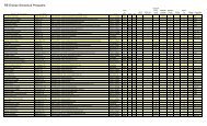
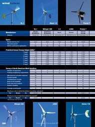
<strong>for</strong> <strong>My</strong><strong>Maine</strong><strong>Workshop</strong>Guy Marsden©2002 Guy MarsdenTubing within the concrete slab floorefficiently distributes solar heat,making a com<strong>for</strong>table room.The author with the solar thermalpanels that heat his workshop’s floor.y wife Rebekah and Idecided to move fromCali<strong>for</strong>nia to rural <strong>Maine</strong> <strong>for</strong>many reasons—mostly to live anaf<strong>for</strong>dable rural lifestyle in a beautifulenvironment. Having survived theCali<strong>for</strong>nia “energy crisis,” we becameeven more energy conscious. Rebekaheven started to refer to me as anenergy nazi!Using solar energy is something I have always wantedto do, ever since reading the Whole Earth Catalog in thelate ’60s. We were <strong>for</strong>tunate enough to make asignificant profit on the sale of our suburban house inCali<strong>for</strong>nia, and used some of the proceeds <strong>for</strong> solarenergy equipment and energy reduction in our newhome in <strong>Maine</strong>.We replaced all the incandescent lamps in the housewith low wattage fluorescent lights, and purchased aStaber clothes washer. We plan to install a grid-intertied,solar-electric system <strong>for</strong> the house this year. Rebekahdrives a 2001 Honda Insight and loves it! She gets anaverage of 61.2 mpg on most trips.34 <strong>Home</strong> <strong>Power</strong> #89 • June / July 2002
<strong>Solar</strong> Space <strong>Heat</strong>ingWe both work at home, and wanted to be sure to havewarm, com<strong>for</strong>table, and well-lit work spaces. Rebekah’sbasement knitting studio is heated by a woodstove thatheats most of the house. A propane backup heater fillsin at night so we don’t have to get up and stoke thestove. Our property includes a recently constructed barnthat is perfect <strong>for</strong> my needs.I make furniture and design electronics <strong>for</strong> a living. So Ineed two distinct work spaces. The barn has a fullsecond floor <strong>for</strong> my electronics lab. That dish antennayou can see above the solar collectors is <strong>for</strong> a StarBandsatellite modem. For my engineering work, I absolutelyrequire high bandwidth. Due to our rural location, asatellite modem is the only viable high-bandwidthoption. As soon as cable internet service is available, Iwill switch, since I find the slow speeds and long delaysof the satellite to be much worse than advertised. Badweather can knock it out entirely!I suffer from migraine headaches that are triggered bycold temperatures, so heating in the <strong>Maine</strong> winters iscrucial <strong>for</strong> my well-being. I decided to use a radiantheated floor, which is known <strong>for</strong> com<strong>for</strong>t. A particularlynice feature is that the heat rises up from the floor towarm my large, floor-mounted power tools. I had nointention of freezing my hands off in the <strong>Maine</strong> winters!The radiant floor is heated primarily by two, 4 by 8 foot(1.2 x 2.4 m) SunEarth Empire series solar collectors,augmented by an AquaStar (AQ125-BLP-S) propaneon-demand water heater.System Design<strong>My</strong> first step was to have a heatload analysis done by PeterTalmage of <strong>Solar</strong> Market inArundel, <strong>Maine</strong>. This helped todefine my heating system designgoals and insulation requirements.The barn was bare stud walls on aconcrete foundation and roughconcrete floor when we acquired it.It had been built to store theprevious owner’s lobster boat.The floor plan is 24 by 28 feet (7 x8.5 m), with a 10 foot (3 m) highceiling on the ground floor and a fullsecond floor. The ground floor isframed with 2 by 6 lumber, and the45 degree roof (un<strong>for</strong>tunatelyfacing east and west) is framedwith 2 by 8 rafters. The barn hadseven original windows, and Iinstalled two, standard, wellinsulatedexterior doors.Sometimes the <strong>Maine</strong> winter is relentless—an AquaStartankless water heater fills in when the sun doesn’t shine.The heating system begins with the two SunEarth solarcollectors that are connected in parallel. A PV poweredpump circulates the heated glycol mixture through aheat exchanger. A second PV powered pump circulatesheated water into the 80 gallon (300 l) storage tank. Athermostat controls the AC pump that feeds the two,300 foot (90 m) loops of tubing in the concrete floor.Guy’s barn was oriented the wrong way to put his solar panels on the roof.The shed Guy built on the south end has a 45 degree roof pitch—perfect <strong>for</strong> the two, 4 by 8 foot solar hot water panels.<strong>Home</strong> <strong>Power</strong> #89 • June / July 200235
<strong>Solar</strong> Space <strong>Heat</strong>ingCorbond spray-on foam insulation has an R-value ofabout 7.3 per inch.InsulatingThe first task of any solar heating design is to get thebest possible insulation <strong>for</strong> the walls, ceiling, and floors,and thoroughly seal any openings that would allowunwanted cold air into the building. I insulated thewindows with removable Windo-Therm interior plasticdouble glazing that will be used only in the cold season(five months in <strong>Maine</strong>).I insulated behind the original sliding barn doors byadding two in-swinging doors, which fit within thedoorway when closed. Resembling hinged wall sections,the auxiliary doors are framed with 2 by 6s, filled withfiberglass, and finished with 3 /8 inch (10 mm) exteriorplywood. They are thoroughly weather-stripped. Theseare huge (4 x 9 foot; 1.2 x 2.7 m) and imposing toopen—I call them the “Doors of Doom!”I contracted the installation of Corbond—a sprayed-inpolyurethane foam insulation—throughout the structure.Corbond has an approximate R-value of 7.3 per inch. Ihad 3 inches (7.6 cm) installed in the walls on theground floor, and 4 inches (10 cm) in the walls upstairs.A significant advantage of the foam is that it <strong>for</strong>ms anairtight seal throughout the building. I left the building toair out all the urethane fumes <strong>for</strong> over four weeks be<strong>for</strong>ecompleting the interior work.The exterior walls of my barn were 1 by 10 inch shiplapbarn boards installed vertically over 1 by 2 inchhorizontal battens. A layer of Tyvek housewrap is inbetween the battens and shiplap. As such, it was farfrom airtight. I added fiberglass inside (over theCorbond) to increase the R-value to about R-30downstairs and about R-40 upstairs, and installeddrywall over that. I estimate that I have approximately R-37 in the roof.Radiant FloorFor the radiant floor, my first job was to install 1 inch (2.5cm) polystyrene high density construction insulationover the existing concrete floor. I then laid 6 inch (15cm) steel grid (commonly referred to as road wire) overthat <strong>for</strong> securing the radiant tubing, using nylon cableties. I laid out two loops of 300 feet (90 m) each of thetubing, which I connected to a manifold in the utilityroom.A local contractor did a great job of pouring 3 inches(7.6 cm) of concrete over the tubing. I asked him to usea 4,000 psi fiberglass mix to give me a strong workshopfloor. Naoto Inoue at <strong>Solar</strong> Market sourced the materials<strong>for</strong> this job and specified the details. He originallysuggested 2 inches (5 cm) of concrete to create a veryresponsive system.Laying 1 inch polystyrene insulation board over the oldfloor insulates the heated slab from the earth.The 600 feet of hydronic tubing is held in place by roadwire. Three inches of concrete will make the final layer.36 <strong>Home</strong> <strong>Power</strong> #89 • June / July 2002
<strong>Solar</strong> Space <strong>Heat</strong>ingHydronic Loop Layout28 feetDoorLarge DoorsThermostatRelay BoxI built a relay box that allows my standard,centralized heating, digital thermostats to control theAC circulation pumps. To power the relays, I used a12 VDC, “wall wart” plug (wall cube, or AC-to-DCconverter), and wired it to solid state relays in a niceplastic box with two LEDs to indicate when eachpump was running. I used solid state relays ratherthan mechanical ones, since they consume afraction of the energy when activated.Door24 feetUtility RoomLoop 1:280 feetLoop 2:300 feetLoops are 6 inches from outer walls and roughly 12 inches apart.I felt that 2 inches would be too thin, and the concretecontractor refused to pour less than 3 inches due to therisk of damaging or exposing the tubing. The 3 inchesstill allows me to use a single household thermostat tocontrol the heating, though it is less responsive. I’m stilltesting, but I believe that the system can raise thebuilding temperature by about 3°F (1.6°C) per hour.The relay box is quite simple. All it contains is a 12VDC power supply, pillaged from an old phoneanswering machine. I actually broke open the plastichousing of the wall wart, and extracted thetrans<strong>for</strong>mer and electronic parts so I could siliconethem into the box nicely. The dissected andreassembled wall wart sends power to thethermostat, which switches the solid state relaysand turns an LED indicator on. The digitalthermostat that I used runs on its own two AAbatteries.The control box LED requires a 1 K-ohm resistor inseries with it <strong>for</strong> current limiting. I used relays thatare rated at 10 amps at 240 volts. These can befound surplus <strong>for</strong> around US$7. When switching amotor with a relay, it is best to rate the relay atdouble the current and voltage of the load to allow<strong>for</strong> protection from the inductive surges that occurduring switching.Building a <strong>Solar</strong> RoofI needed a structure on the south side of the barn to putthe solar collectors on, so I built a small shed with asteeply sloped roof. At this latitude, a 45 degree slope isrecommended and is easy to build.<strong>My</strong> neighbor John Rogers, who is a building contractor,helped me design the shed and gave me a hand <strong>for</strong> anhour or so to get the collectors mounted on the roof. Iwas lucky that the weather was still warm enough tosweat the exposed 3 /4 inch copper pipe fittings in earlyOctober! <strong>Maine</strong> can be quite chilly at that time of year!The collectors came with small L-brackets that did notseem to be big enough to raise the collectors more than1 /2 inch (13 mm) off the asphalt roof. Ken Olsonsuggested that an inch or so would be better, so I madeup my own brackets from extruded, 3 inch (7.6 cm)angle aluminum with a 1 /8 inch (3 mm) wall.A homebuilt, solid-state relay box allowsstandard thermostats to control the system’sAC circulation pumps.<strong>Home</strong> <strong>Power</strong> #89 • June / July 200237
<strong>Solar</strong> Space <strong>Heat</strong>ingHot to Storage Tank<strong>Heat</strong>ExchangerTank LoopCirculatorPumpExpansion TankCold fromStorageTankHot from<strong>Solar</strong>CollectorsTemperatureGaugeTemperatureGaugePressureGaugeCold to<strong>Solar</strong>Collectors<strong>Solar</strong>CollectorLoopCirculatorPumpPressureRelief ValveI used three, stainless steel, sheetmetal screws toattach each 3 inch long bracket to the collectors, andused a 5 /16 inch by 2 inch (8 x 50 mm) stainless lagscrew with galvanized washers per bracket to securethem to the roof. I also put a bit of silicone around thelag screw heads to prevent ice from working down intothe roof.Lots of PlumbingOne thing that is rarely mentioned in articles abouthomebrew solar installations is the emotional ride. Forme, it has ranged from excitement to total freak out atthe daunting complexity and overwhelming amount ofdetail. Fortunately, I already had considerableexperience in all the skills needed to accomplish myinstallation, so I was able to trust in my knowledge that Icould complete the project almost single-handedly.I am an experienced home and light industrial plumberfrom a previous life in photo processing. Nonetheless, ittook many visits to the hardware store over a period of acouple of weeks to locate all the copper fittings <strong>for</strong> thesystem components. The plumbing assembly took morethan a week to build. I sweated together each section ofthe various assemblies of valves, gauges, and pumps,which I then assembled into a complete system.It was very helpful and timely that HP85 came out as Ibegan the plumbing phase. That issue contains KenOlson’s excellent article on closed loop antifreezesystems. I downloaded a copy and used it as a workingreference on the job.Some Plumbing TricksOne neat plumbing solution that I found was a good wayto mount thermometers into 3 /4 inch copper pipe. Thethermometers that I used come standard with a 1 /2 inchpipe thread, and if you sweat a 1 /2 inch thread adapteronto a 3 /4 inch tee with a short length of 3 /4 inch pipe, thethermometer sensor stays out of the fluid flow. This cangive inaccurate readings, especially if the tee ismounted so that air stays trapped in the stub tube.A brass seat teewith reducer(right) keepsthe thermometersensor inthe fluid’s flow.Copper fittings(left) don’t workas well.The solar loop portion of the system’s plumbing,showing the Amtrol 2 gallon expansion tank, Secespolheat exchanger, and 2 El Sid circulating pumps.38 <strong>Home</strong> <strong>Power</strong> #89 • June / July 2002
<strong>Solar</strong> Space <strong>Heat</strong>ingGuy Marsden’s <strong>Solar</strong> <strong>Heat</strong>ing SystemAirVentPhotovoltaic Modules:Two, 10 watt and one, 20 watt<strong>Solar</strong>ex PV modules,power 12 VDC El Sid pumpsBackup <strong>Heat</strong>er:AquaStar AQ125-B2P-S,propane fueled,on-demandExpansion Tank:Amtrol, 2 gallonExpansion Tank:Amtrol, 2 gallonTemperatureGauge<strong>Solar</strong> ThermalModules:Two, SunEarthEmpire series,4 x 8 footValve:BallValve:BallCheckValveValve:Temperature/Pressure ReliefPressureGaugeAir VentTemperatureGaugeValve:BallValve:BallTemperatureGaugeOut to future loopValve:BallPumps:Taco 006, 120 VACTemperatureGaugeManifold:Hydronic loop supply<strong>Heat</strong>Exchanger:Secespol B 130Pumps:El Sid, 10 W,3 gpmValve:FillOut to floor loopValve:BallManifold:Hydronic loop returnValve:DrainValve:BallPressureGaugeValve:FillValve:Temperature/Pressure ReliefValve:DrainTank:Rheem, 80 gallonThreaded Union: Allows <strong>for</strong> easyremoval and replacement of componentTemperatureGaugeIn from floor loopValve:FillI used a brass sweat tee with 1 inch female threadsinstead. Then by putting in a 1 /2 inch reducer bushing, Ifound that the thermometer’s 1 /2 inch thread would fit insnugly, allowing the thermometer sensor to protrudefully into the water flowing through the tee. I believe thatthis setup will guarantee accurate readings.When plumbing the indoor section of the collector loop, Iplaced unions around the heat exchanger and pumpsections. The sections can be removed easily <strong>for</strong>service or replacement, or to tighten the couplings. Itturned out that I needed to make use of this feature, soit definitely paid off.Another trick that I devised involves weatherizing thefoam insulation on the exterior plumbing. I took some 2inch PVC pipe and ripped it in half on my table saw andclamped it back around the insulated pipe using nyloncable ties.The air vent needs to be located at the highest point inthe system, which means at the top corner of thecollectors <strong>for</strong> me. I ended up with a vent that is about 6inches (15 cm) above the collectors. To insulate andprotect it from the elements, I wrapped the pipe in foam,and put a length of PVC pipe with an end cap over it.<strong>Home</strong> <strong>Power</strong> #89 • June / July 200239
<strong>Solar</strong> Space <strong>Heat</strong>ingThat’s not Gatorade! Filling and pressurizing the solar collector loopwith the propylene glycol solution.temperature rises to a maximum.Stagnation temperatures willeventually break down most types ofglycol. Stagnation should be avoidedin closed loop systems unless hightemperature (350°F; 177°C) propyleneglycol is used.The Break-In PeriodAfter a late night of filling andchecking the system, I was up withthe sun the next morning to watchthe solar powered El Sid circulatingpump kick in and begin warming mysystem. I was disappointed at howlong it seemed to take with the sunshining brightly, until I realized that Ihad installed the pump in the wrongdirection. The pump was trying tosuck against the check valve to noavail. Being quite dyslexic, this issomething I have grown used to—getting things backwards!Filling the System<strong>My</strong> workshop has no running water, so I had to pull agarden hose over 70 feet (21 m) from the house to fillthe system. I came up with a neat way to monitor thefluid and air bubbles entering and exiting the system. Imade up two, 3 foot (0.9 m) lengths of 5 /8 inch (16 mm)ID clear plastic hose and added garden hose fittings.One hose was connected to the fill pump outfeed, andthe other to the system drain. This made it possible tomonitor the fill process, and to clearly see when the airwas purged from the system.I let the fill pump continue to recirculate until thereturning fluid stopped showing air bubbles. Air bubblesin a closed system can impede flow and limit theefficiency of the system, and should be carefully andthoroughly eliminated. When filling the water tank, Iattached the clear plastic infeed hose directly to agarden hose, and let the overflow drain out the window!<strong>My</strong> solar collector loop holds approximately 3 gallons(11 l), so it was relatively easy to prepare a 50:50 glycolsolution by mixing it in a 5 gallon (19 l) bucket. Usepropylene, not ethylene, glycol. Ethylene glycol, as usedin automobile radiators, is highly toxic. The propyleneglycol that I used is <strong>for</strong>mulated <strong>for</strong> the hightemperatures that the collectors can generate.The SunEarth collectors can reach a stagnanttemperature of 240°F (116°C). A collector will achieveits hottest temperatures under what is called stagnationconditions. When no fluid is flowing through thecollectors, heat is not being removed, and theThe supply and return manifolds of the two hydronicfloor loops. Notice the extra Taco 006 pump <strong>for</strong> a futureheating loop in the barn’s second floor.Pump ControllerRelayCirculatingPumpsSupplyManifoldHotto FloorHot fromStorage Tank /AquastarAquaStarTankless Water <strong>Heat</strong>erReturnManifoldTemperatureGaugesColdfrom FloorCold to Storage Tank40 <strong>Home</strong> <strong>Power</strong> #89 • June / July 2002
<strong>Solar</strong> Space <strong>Heat</strong>ingThe liberal use of threaded unions allows <strong>for</strong> easyremoval of components <strong>for</strong> repair or replacement.Fortunately, I had installed unions around the pump withserviceability in mind, so I simply closed some valvesand removed the section. I unscrewed the fittings oneach side of the pump, reversed it, and reinstalled it.The moment the pump began to run, I watched theincoming temperature gauge rise to over 220°F (104°C)from the stagnant hot water in the collectors. In a fewminutes, it settled down to a nominal 155°F (68°C),which seemed to be the system’s normal capacity(more on that later).I wholeheartedly recommend that all systems have aliberal sprinkling of unions to allow <strong>for</strong> servicedisassembly. I also found some leaks around my heatexchanger, and rectified that by removing the wholeassembly and tightening the fittings.PV & Collector ProblemsIn the first few days of full sun, I noticed that the pumpdidn’t kick in until after 10:30 AM. I first thought that thesolar-electric panel that runs the circulation pump wasunderpowered. On the third sunny morning, I went outand looked at the PV panel. I saw that I had mounted itup slope from the air vent I had installed on a 6 inch (15cm) extension above the collectors, and the air vent wasshadowing the PV! So I moved it over by a foot andfixed that silly mistake!When I mentioned to Naoto that my operatingtemperature was a nominal 155°F (68°C), he wassurprised, since the design spec is closer to 180°F(82°C). He had been having trouble with other SunEarthEmpire series units underper<strong>for</strong>ming, and contacted thefactory.The SunEarth engineers were very responsive andsoon learned that there was a manufacturing defect inthe units. They arranged with <strong>Solar</strong> Market to replaceThe air vent shaded the PV panels in the early morning,causing a delay in pump operation—Oops!those units that were already installed. The first set ofreplacements I received was not packed properly andthe panels were badly damaged in shipping. Almost fourmonths later, I finally have the new units, and must nowwait <strong>for</strong> a warm, dry day! Right now it’s inches of mudand raining hard, with snow in the <strong>for</strong>ecast! Check myWeb site <strong>for</strong> details on the new panels and theirper<strong>for</strong>mance.Underpowered Floor Circulating PumpsThe next setback came when the propane suppliercame to hook up the AquaStar heater. We couldn’t getthe heater to kick in, even though the circulating pumpwas running. I realized that mine is a closed system,and the AquaStar relies on a pressure difference of 10psi to turn on.This is fine in an open system. When you turn on afaucet, the outfeed pressure drops, turning the heaterburner on to the degree needed to bring the waterflowing through it to temperature. It looked like the pump(Taco 003 series) was underpowered. This was verydistressing!I called Naoto at <strong>Solar</strong> Market and he immediately droveover (a trip of more than an hour!) in his biodiesel<strong>Home</strong> <strong>Power</strong> #89 • June / July 200241
<strong>Solar</strong> Space <strong>Heat</strong>ingMarsden <strong>Heat</strong>ing System CostsItemCost (US$)2 SunEarth Empire series 4 x 8 foot collectors 952AquaStar 125BS propane water heater 6901,000 ft. Rehau radiant floor tube, 1 /2 inch (600 ft. used) 616Lumber <strong>for</strong> shed 580Copper pipe, fittings, valves, etc., 3 /4 inch 5002 El Sid PV-driven circulating pumps, 3 GPM 10 W 420Rheem storage tank, 80 gallons 3692 Taco circulating pumps, model 006, 120 VAC 332Secespol B 130 heat exchanger 2562 <strong>Solar</strong>ex SX-10M PV modules, 12 V, 10 W 212<strong>Solar</strong>ex SX-20M PV module, 12 V, 20 W 1802 Manifolds, 6 outputs & 6 valves <strong>for</strong> floor tubes 138Wayne PC2 utility pump, 60 gph at 40 feet of head 855 Temperature gauges 802 Amtrol 2 gal. expansion tanks, high temperature 76Check valve, light-action spring 24Amtrol air vent 9powered Mercedes. He brought a larger pump. Naotohas been unfailingly supportive and helpful throughoutthe entire project. I simply couldn’t have done it allwithout his help and advice. We were lucky that thelarger pump (Taco 007 series) that he brought was thesame brand and used the same size motor body as theunderpowered unit.The quick fix was to remove the motor from its housingand replace it with the larger motor and impeller. Thissaved a lot of work replumbing all the copper! Themodified pump created enough draw to pull a pressuredrop across the AquaStar and trigger it to fire up itsburners.After running this modified pump <strong>for</strong> several days, Inoticed that it ran hot—too hot to touch com<strong>for</strong>tably. Idecided to call the manufacturer, Taco, Inc. Theapplication engineers there were very helpful andreviewed my design thoroughly. They asked me to takeamp readings while the pump was running, and also rana lab simulation of my system configuration.Their conclusion was that I would be better served by a006 series pump. It comes with 3 /4 inch sweat fittingsrather than the 1 /2 inch sweat fittings that I had used withthe original 003 series unit. This model is also moreefficient electrically. The 007 model is rated at 0.7 amps,while the 006 model is rated at 0.52 amps. Both pumpsoperate at 120 VAC. I found that the rated amps are arough value, and the actual draw varies with theoperating temperature of thepump—cooler equals lower current.<strong>My</strong> pumps seem to run a bit lowerthan their rated specs even afterrunning <strong>for</strong> hours.The Taco engineers were kindenough to send me replacementpumps to solve my design issue. Itrequired resweating a chunk of mymanifold, and refilling my system, butit was worth it if only to reduce myelectrical load!When Naoto came by with thereplacement pump, he reviewed thedetails of my system with me. Heagreed with my assessment that thesystem efficiency could be improvedby pumping heated water throughthe heat exchanger. In the originaldesign, heat flowing up through thesecondary side of the heatexchanger would create aTotal $5,519thermosiphon effect to heat thewater stored in the tank. <strong>My</strong> feeling isthat this flow is insufficient to maximize the potentialheat transfer capability of the heat exchanger. <strong>Heat</strong>rising through the heat exchanger does not flow asrapidly as it would if pumped.We decided to add another PV panel with its ownseparate DC pump installed on the cold side of the heatexchanger. The neat thing about circulation pumps thatare direct wired to PV panels is that they only operatewhen there is sufficient sun to heat the solar collectors.We also decided to add a temperature gauge be<strong>for</strong>e theAquaStar heater, at the storage tank exit. Previously, Ihad no way of monitoring the temperature of the solarheated water emerging from the storage tank.Underpowered PV Circulating PumpsAnother issue arose when I noticed that the PV-drivencirculation pumps didn’t kick in until well after sunrise onsunny days. I e-mailed Dan Fieldman at Ivan Labs andasked what might be wrong. He explained that herecommends 20 watts of PV per pump when they areinstalled north of Jacksonville, Florida. He alsocorrected me on the orientation of my pump—the motorshould be horizontal, not vertical.Since the pumps are rated at 10 watts, <strong>Solar</strong> Markethad sold me one 10 watt <strong>Solar</strong>ex PV panel per pump. Ihave added another 20 watt <strong>Solar</strong>ex unit <strong>for</strong> a total of 40watts wired in parallel to run both my El Sid circulationpumps. This has dramatically increased my systemefficiency.42 <strong>Home</strong> <strong>Power</strong> #89 • June / July 2002
<strong>Solar</strong> Space <strong>Heat</strong>ingGuy Marsden installed the whole solar hydronic heatingsystem himself.Learning How to Best Use <strong>Solar</strong> <strong>Heat</strong>I bought a standard electronic thermostat <strong>for</strong> spaceheating systems that has four settings per day. Itincluded a mode <strong>for</strong> radiant floor heating that makes itshut off as soon as the temperature is 1°F (0.56°C)above the setpoint. Originally, I set it to 60°F (16°C) atnight, and 68°F (20°C) at 7 AM. I learned that this is thewrong thinking <strong>for</strong> a radiant floor, solar heating system.<strong>My</strong> system has a very slow response time. So settingthe temperature low at night appears to be a falseeconomy, since it takes several hours to get back up to68°F (20°C) in the morning. I experimented and learnedto set the thermostat to 70°F (21°C) from 5 to 9 AM, andto 67°F (19°C) <strong>for</strong> the rest of the day.The heat coasts up by several degrees during the two tofour hours after the circulation pumps shut off. Thebuilding is so well insulated that when the heat shuts offbetween 9 and 11 AM (on days well below freezingoutside), it does not come on again <strong>for</strong> over twelvehours. On days where the outside temps stay below10°F (-12°C), the heat stays on all night, and cuts offmidmorning when 67°F (19°C) has been reached.There is enough direct solar gain from windows thatsunlight plays a big factor in daytime heating.Many radiant floor solar heating systems suffer from anoverproduction of heat in the summer, since there islittle or no space heating load. <strong>My</strong> understanding is thatthe antifreeze <strong>for</strong>mulation in the Dow Frost propyleneglycol mixture that I used is rated to 350°F (177°C), asopposed to other mixtures that are only rated to 280°F(138°C).In the summer months, I’m going to disconnect the PVmodules from the circulation pumps and let the collectorloop fluid stagnate. This will shorten the life of the glycolin the system, but I still expect to get five years or so outof it be<strong>for</strong>e it needs to be changed. I plan on checkingthe pH of the glycol be<strong>for</strong>e the heating season begins tomake sure it hasn’t degraded and is up to snuff.You can see a detailed journal with many images of thewhole process of building this system on my Web site. Iam now enjoying building furniture in a warm workspace. It is a very efficient system, and best of all—it’sheated by the sun! Radiant heat makes a verycom<strong>for</strong>table work environment, and I have found that Iam setting the thermostat lower than I had expected.AccessGuy Marsden, Art Tec, 61 Delano Road, Woolwich, ME04579 • 207-443-8942 • Fax: 207-443-8677guy@arttec.net • www.arttec.net/<strong>Solar</strong>/Barn<strong>Heat</strong>.html<strong>Solar</strong> Market/Talmage <strong>Solar</strong> Engineering, Inc., 25Limerick Rd., Arundel, ME • 877-785-0088 or207-985-0088 • Fax: 207-985-5577naoto@solarmarket.com • www.solarmarket.comWindo-Therm, 2746 NY 7, Valley Falls, NY 12185800-819-9463 • Fax: 518-663-7678windo@albany.net • www.windotherm.comCorbond Corporation, 32404 Frontage Rd., Bozeman,MT 59715 • 888-949-9089 or 406-586-4585corbond@corbond.com • www.corbond.com • CorbondinsulationRadiant Floor Company, PO Box 666, Barton, VT05822 • 866-927-6863 or 802-525-1132Fax: 802-525-3940 • info@radiantcompany.comwww.radiantcompany.comControlled Energy Corp., 340 Mad River Park,Waitsfield, VT 05673 • 800-642-3199 or 802-496-4357Fax: 802-496-6924 • sales@controlledenergy.comwww.controlledenergy.com • AquaStar tankless waterheaterTaco, Inc., 1160 Cranston St., Cranston, RI 02920401-942-8000 • Fax: 401-942-2360marcha@taco-hvac.com • www.taco-hvac.comIvan Labs, Inc., Dan I. Fieldman, 305 Circle West,Jupiter, FL 33458 • 561-747-5354 • Fax: 561-746-9760ivandelsol@juno.com<strong>Home</strong> <strong>Power</strong> #89 • June / July 200243