01 NFPA.pdf - Norgren Pneumatics. Motion Control Equipment ...
01 NFPA.pdf - Norgren Pneumatics. Motion Control Equipment ...
01 NFPA.pdf - Norgren Pneumatics. Motion Control Equipment ...

Create successful ePaper yourself
Turn your PDF publications into a flip-book with our unique Google optimized e-Paper software.
Piston Rod Diameter Selection<br />
Applications requiring long extend (push) strokes may require oversize<br />
piston rod diameters to prevent buckling.<br />
To determine the correct rod diameter for your application<br />
follow these simple steps:<br />
1. Select the force from the Cylinder Force and Volume Chart that is<br />
required for your application. For pressures not shown use:<br />
Force = Piston Surface Area x Operating Pressure<br />
2. From the Cylinder Mounting Diagram Chart (next page) select the<br />
mounting style being used.<br />
3. To obtain effective length “L”, multiply cylinder stroke by appropriate<br />
stroke factor located in Cylinder Mounting Diagram Chart . If cylinder<br />
has extra rod extension add this to the stroke length before obtaining<br />
effective length. Effective Length = Actual Stroke x Stroke Factor<br />
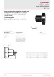
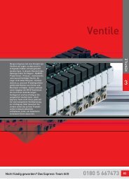
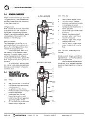
Stop Tube<br />
Enhances the transverse load carrying<br />
capability of a long stroke cylinder by<br />
increasing the distance between the piston<br />
and rod bearing at full extension when<br />
placed on head end. Ideal for those<br />
applications requiring longer strokes or<br />
where additional rod stability is desired.<br />
TO ORDER: Enter option code ST(–C) Cap<br />
End or ST(–R) Rod End. Specify stop tube<br />
length.<br />
NOTE: ST(–R) Alternate design: the stop tube<br />
rod end design changes when the stop tube<br />
exceeds J lengths in the chart.<br />
<strong>NFPA</strong> Aluminum & Steel Cylinders<br />
4. To determine adequate rod diameter locate calculated effective length<br />
“L” on Rod Selection chart (below).<br />
5. Selecting Stop Tubes: Stop tubes enhance the transverse load carrying<br />
capability of a long stroke cylinder by increasing the distance between<br />
the piston and rod bearing at full extension. When the value of L<br />
(calculated from the Adequate Rod Diameter Chart) is less than 40", a<br />
stop tube is not required. However, if L is 40" or more, 1" of stop tube<br />
is recommended for every 10" (or fraction thereof) over 40".<br />
6. Recommended Mounting Styles for Maximum Stroke and Thrust Load:<br />
• Multiply cylinder stroke by appropriate stroke factor to obtain<br />
effective length L.<br />
• If cylinder has extra rod extension, add this extension to the stroke<br />
length before obtaining effective length.<br />
ST(–C) ST(–R) ST(–R)<br />
Stop Tube Length<br />
Cap Stop Tube<br />
Stop Tube Length<br />
Head Stop Tube<br />
Stop Tube Length<br />
Head Stop Tube<br />
consisting of Spacer<br />
Tube and Block<br />
Bore 1-1/2" (38.10) 2" (50.80) 2-1/2" (63.50) 3-1/4" (82.55) 4" (1<strong>01</strong>.60) 5" (127.00) 6" (152.40) 7" (177.80) 8" (203.20)<br />
J 1 (25.40) 1 (25.40) 1 (25.40) 1.250 (31.75) 1.250 (31.75) 1.250 (31.75) 1.500 (38.10) 1.500 (38.10) 1.500 (38.10)<br />
Rod Selection Chart<br />
Extended Force Maximum effective length “L” recommended for rod diameters<br />
(lbs) 5/8" 1" 1-3/8" 1-3/4" 2" 2-1/2"<br />
50 95 – – – – –<br />
100 65 170 – – – –<br />
150 50 135 260 – – –<br />
200 43 115 220 – – –<br />
300 34 93 180 300 – –<br />
500 25 70 135 250 – –<br />
750 20 56 110 185 250 –<br />
1000 17 48 94 160 220 –<br />
1500 13 38 80 130 170 260<br />
2000 11 33 64 110 140 225<br />
3000 9 26 51 90 115 180<br />
4000 7 22 44 75 100 155<br />
5000 – 20 39 66 88 140<br />
6000 – 18 35 60 79 125<br />
8000 – 15 30 52 68 110<br />
10000 – 12 26 46 60 95<br />
12500 – 10 22 41 52 86<br />
15000 – – 19 37 48 79<br />
20000 – – 14 29 41 68<br />
Note: In some cases it may be necessary to use a larger bore cylinder than is required for force in order to obtain an adequate rod diameter.<br />
J<br />
ACT-25<br />
ACTUATORS