01 NFPA.pdf - Norgren Pneumatics. Motion Control Equipment ...
01 NFPA.pdf - Norgren Pneumatics. Motion Control Equipment ...
01 NFPA.pdf - Norgren Pneumatics. Motion Control Equipment ...

Create successful ePaper yourself
Turn your PDF publications into a flip-book with our unique Google optimized e-Paper software.
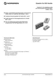
ACTUATORS<br />
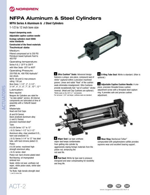
<strong>NFPA</strong> Aluminum & Steel Cylinders<br />
<strong>NFPA</strong> Series A Aluminum & J Steel Cylinders<br />
1-1/2 to 12 inch bore size<br />
Impact dampening seals<br />
Adjustable captive cushion needle<br />
Ecology cylinders meet OSHA<br />
noise standards<br />
Constructed of the finest materials<br />
Technical data<br />
Medium:<br />
Filtered compressed air to 250 PSI<br />
Petroleum based hydraulic fluid to<br />
400 PSI*<br />
Operating temperature:<br />
Series A & J -20°F to 200°F<br />
with Viton Seals -20˚F to 400˚F<br />
Operating Pressure:<br />
250 PSIG Air, 400 PSIG Hydraulic*<br />
non-shock.<br />
NOTE: EA and EJ max pressure<br />
rating: 150 psi.<br />
Bore Sizes: 1-1/2", 2", 2-1/2",<br />
3-1/4", 4", 5", 6", 7", 8", 10"*, 12"*<br />
Lubrication:<br />
None required<br />
<strong>Norgren</strong> Air Cylinders are rated for<br />
“no lube added” service. All internal<br />
components are lubricated at time of<br />
assembly with a Teflon® based<br />
grease.<br />
Materials<br />
Head and End Caps:<br />
(A and EA Series)<br />
black anodized aluminum alloy<br />
(J and EJ Series)<br />
precision machined steel*<br />
Tube:<br />
A & EA Series 1/2" to 12"<br />
J & EJ Series 1-1/2" to 2-1/2"<br />
Aluminum alloy, clear anodized O.D.,<br />
hard coat anodized I.D.<br />
J & EJ Series 3-1/4" to 12" has steel<br />
tube, with hard chrome plated I.D.<br />
Piston:<br />
A & EA series: machined highstrength<br />
aluminum alloy.<br />
J & EJ series: steel<br />
Piston rod: hard chrome plated steel<br />
Rod Bearing: oil impregnated<br />
sintered iron<br />
Seals: nitrile rod seal, urethane rod<br />
wiper, nitrile piston seals, nitrile tube<br />
end seals<br />
Tie Rods: high-tensile strength steel<br />
* J and EJ series only<br />
ACT-2<br />
Ultra Cushion ® 1<br />
Seals: Advanced design 2 O-Ring Tube Seal: Nitrile is standard. (Viton is<br />
features a unique, one-piece, compound seal of<br />
nitrile* captured within a precision machined<br />
optional.)<br />
groove. Linear and radial “float” of the cushion<br />
seals eliminates misalignment. Ultra Cushions<br />
provide exceptionally fast “out of cushion” stroke<br />
reversal. (Head and Cap Cushions are optional.)<br />
*Nitrile seals on the 5/8" & 1" rod diameter.<br />
3 Adjustable Captive Cushion Needle: A onepiece,<br />
precision threaded brass cushion<br />
adjustment screw with a threaded steel capture<br />
ring. It provides safe and precise cushion<br />
For rod sizes 1-3/4" and larger, urethane seals are standard. adjustment.<br />
6<br />
4<br />
1 2<br />
4 Wiper Seal: Lip-type urethane<br />
wiper seal keeps contaminates<br />
from getting into cylinder by<br />
aggressively wiping foreign materials from the<br />
piston rod, enhancing the<br />
rod seal life.<br />
6 Rod Seal: Nitrile lip type seal is pressure<br />
energized and wear compensating for durability<br />
and long life.<br />
3<br />
Wear Ring: Reinforced Teflon ®<br />
5<br />
compounded with polyphenylene sulfide provides<br />
supreme wear and excellent bearing support.<br />
www.norgren.com/info/US-ACT-2<br />
5<br />
3
Series A Cylinders are constructed with the finest materials for each component!<br />
1 Piston Rod: Hard chrome plated high-tensile<br />
steel, ground and polished.<br />
2 Rod Bearing: External removable threaded<br />
steel bearing housing (black oxide finish), with an<br />
oil-impregnated sintered iron rod bearing.<br />
3 Rod Seal: Nitrile lip-type seal<br />
is pressure energized and wear compensating for<br />
durability and long life.<br />
4 Head/Cap: Precision machined from alloy<br />
aluminum, then anodized for corrosion resistance<br />
(black finish).<br />
1<br />
2<br />
10<br />
10 Wiper Seal: Lip-type urethane<br />
wiper seal keeps contaminates<br />
from getting into cylinder by<br />
aggressively wiping foreign materials from the<br />
piston rod, enhancing the<br />
rod seal life.<br />
Application Information<br />
Series A <strong>NFPA</strong> interchangeable aluminum air cylinders<br />
are offered with a variety of accessories, standard and<br />
optional equipment to meet your application needs.<br />
3<br />
4<br />
5<br />
Ultra Cushion ® 5<br />
Seals: Advanced design<br />
features a unique, one-piece, compound seal of<br />
nitrile* captured within a precision machined<br />
groove. Linear and radial “float” of the cushion<br />
seals eliminates misalignment. Ultra Cushions<br />
provide exceptionally fast “out of cushion” stroke<br />
reversal. (Head and Cap Cushions are optional.)<br />
*Nitrile seals on the 5/8" & 1" rod diameter.<br />
For rod sizes 1-3/8" and larger, urethane seals are standard.<br />
6 O-Ring Tube Seal: Buna is standard. (Viton is<br />
optional.)<br />
6<br />
9<br />
11 Cylinder Tube: High-strength aluminum<br />
alloy ideally suited for air service. The tube is<br />
clear anodized on the O.D. and hard anodic<br />
coated on the I.D., resulting in a smooth, file<br />
hard (60RC), corrosion and score resistant<br />
surface finish.<br />
The addition of a Teflon ® wear ring to the<br />
outer perimeter of the piston permits us to guarantee<br />
its operation against failure due<br />
to lack of lubrication for ONE FULL YEAR, regardless of<br />
cycles! See page ACT-1-98 for complete warranty.<br />
7<br />
11<br />
7 Tie Rods: High-strength steel maintains uniform<br />
compression on tube end seals.<br />
8 Piston: Machined solid aluminum alloy, lightweight<br />
for low inertia, yet strong. Threaded piston<br />
is installed with high strength threadlocker<br />
adhesive then staked to the piston rod.<br />
9 Adjustable Captive Cushion Needle: A onepiece,<br />
precision threaded brass cushion<br />
adjustment screw with a threaded steel capture<br />
ring. It provides safe and precise cushion<br />
adjustment.<br />
8<br />
12<br />
13<br />
12 Piston Seals: Long-wearing<br />
nitrile seals.<br />
6<br />
12<br />
Wear Ring: Reinforced Teflon ®<br />
13<br />
compounded with polyphenylene sulfide provides<br />
supreme wear and excellent bearing support.<br />
Standard non-cushioned Series A cylinders are<br />
recommended for applications that require full<br />
bottoming of the piston and where the noise emitted by<br />
the metal-to-metal impact between the piston and<br />
cylinder end caps is tolerable. We recommend that<br />
optional non-adjustable cushions be added for piston<br />
speeds (moving light tools) ranging from 15 to 30<br />
in/sec. For speeds exceeding 30 in/sec, the cylinders<br />
should be equipped with adjustable air cushions.<br />
4<br />
9<br />
ACT-3<br />
ACTUATORS
ACTUATORS<br />
<strong>NFPA</strong> Aluminum & Steel Cylinders<br />
Series EA Ecology Cylinders are constructed with the finest materials for<br />
each component!<br />
Ultra Cushion ® 1<br />
Seals: Advanced design<br />
features a unique, one-piece, compound seal of<br />
nitrile* captured within a precision machined<br />
groove. Linear and radial “float” of the cushion<br />
seals eliminates misalignment. Ultra Cushions<br />
provide exceptionally fast “out of cushion” stroke<br />
reversal. (Head and Cap Cushions are optional.)<br />
*Nitrile seals on the 5/8" & 1" rod diameter.<br />
For rod sizes 1-3/8" and larger, urethane seals are standard.<br />
8<br />
4<br />
ACT-4<br />
1<br />
2 2<br />
9<br />
3<br />
10<br />
8 Head/Cap: Precision machined from alloy<br />
aluminum, then anodized for corrosion<br />
resistance (black finish).<br />
Wear Ring: Reinforced Teflon ® 9<br />
compounded<br />
with polyphenylene sulfide provides supreme<br />
wear and excellent bearing support.<br />
2 Impact Dampening Piston Seals: Our impact<br />
dampening piston seals, in conjunction with our<br />
advanced cushion design, decelerate and reduce<br />
end-of-stroke noise.<br />
3 Piston: Machined solid aluminum alloy, lightweight<br />
for low inertia, yet strong. Threaded<br />
piston is installed with high strength<br />
threadlocker adhesive then staked to the piston<br />
rod.<br />
4 O-Ring Tube Seal: Buna is standard. (Viton<br />
is optional.)<br />
11<br />
10 Tie Rods: High-strength steel maintains<br />
uniform compression on tube end seals.<br />
11 Cylinder Tube: High-strength aluminum alloy<br />
ideally suited for air service. The tube is clear<br />
anodized on the O.D. and hard anodic coated on<br />
the I.D., resulting in a smooth, file hard (60RC),<br />
corrosion and score resistant surface finish.<br />
1<br />
4<br />
5 Adjustable Captive Cushion Needle (not<br />
shown): Fine thread allows for safe and<br />
precision adjustment of cushion. (See ACT-5.)<br />
6 Wiper Seal: Lip-type urethane wiper seal<br />
keeps contaminates from getting into cylinder<br />
by aggressively wiping foreign materials from<br />
the piston rod, enhancing the rod seal life.<br />
7 Piston Rod: Hard chrome plated high-tensile<br />
steel, ground and polished.<br />
8<br />
12<br />
13<br />
6<br />
12 Rod Seal: Nitrile lip-type seal is pressure<br />
energized and wear compensating for<br />
durability and long life.<br />
13 Rod Bearing: External removable steel<br />
bearing housing (black oxide finish), with an<br />
oil-impregnated sintered iron rod bearing.<br />
www.norgren.com/info/US-ACT-4<br />
7
<strong>Norgren</strong> Ecology Cylinders offer these advantages:<br />
1 2<br />
<strong>Norgren</strong> Guarantees<br />
Non-lubricated Operation<br />
for a Full Year!<br />
The piston rod is self-lubricated by the oilimpregnated<br />
rod bearing during operation.<br />
Lubrication between piston and cylinder barrel is<br />
derived from the polishing qualities of the<br />
reinforced Teflon ® wear ring.<br />
The low friction surfaces extend the life of the<br />
seals beyond normal expectations, permitting<br />
<strong>Norgren</strong> to unconditionally guarantee<br />
non-lubricated operation for one full year.<br />
Series EA cylinders are <strong>NFPA</strong> interchangeable<br />
and are available in many different mounting<br />
styles.<br />
3Energy Absorption<br />
Capacity of the Impact<br />
Dampening Seals<br />
The impact-dampening Piston Seals in the<br />
Series EA cylinder allow for guaranteed,<br />
repeatable cushioning. The compressive<br />
qualities of the piston seals are predictable.<br />
The degree of seal compression at various<br />
supply pressures is documented. (See Energy<br />
Absorption Chart.) This allows you to compute<br />
the exact cylinder size required by knowing the<br />
weight (pounds) you are stopping at a given<br />
speed.<br />
Series EA cylinders have a impact dampening<br />
piston seal that accomplishes 80% of the<br />
actual load stopping. The air cushion accounts<br />
for only 20%. (A conventional air cushioning<br />
cylinder depends 100% on the compressibility<br />
of air to do the stopping.) The EA seal absorbs<br />
high impact loads allowing the effect of the air<br />
cushion to be reduced by using a larger air<br />
cushion bleed orifice. As a result the piston can<br />
move at a faster speed for a longer period of<br />
time before the EA seal does the final stopping.<br />
See illustration at top of ACT-4 for cushion<br />
operation.<br />
<strong>NFPA</strong> Aluminum & Steel Cylinders<br />
Operates Quietly<br />
to Meet<br />
OSHA Specifications.<br />
Series EA cylinders provide substantial<br />
reductions in impact noise, which reduces overall<br />
machine noise and helps meet government<br />
regulations.<br />
Summary of Sound Levels in Decibels<br />
PSI Air Sound<br />
Cylinder Model<br />
Pressure A133B3 EA155B3 A1133A3 EA1155A3<br />
Level+ 5" x 6" 5" x 6" 2" x 6" 2" x 6"<br />
95 End++ 108 73 110 74<br />
PSI+ Side++ 112 84 110 81<br />
50 End++ 108 73 113 74<br />
PSI+ Side++ 113 85 110 81<br />
*The weight of the cylinder piston has been deducted from the figures shown above.<br />
Note: The use of Viton ® Seals limits the absorption of the impact dampening seals by 50%.<br />
Effect of Impact Dampening Seals on Total Stroke of Cylinders<br />
The summary of sound decibels chart illustrates<br />
the operating sound levels.<br />
The impact dampening qualities of the Piston<br />
Seals are guaranteed for ONE FULL YEAR!<br />
+ Peak sound pressure is given in decibels (dB)<br />
re:2 x 10 5 N/m 2 .<br />
++End position of mike was 3' on centerline from end of<br />
cylinder; side position of mike was 3' perpendicular to<br />
centerline abeam of end of cylinder.<br />
Note: At 5 feet, cylinder sound levels would be less by 9 dB from<br />
side figure and 13 dB from end figure. The total noise emitted will<br />
depend on the structure to which the cylinder is attached. If it is<br />
mounted on a thin flat plate of considerable area, the noise will<br />
be increased by a sounding board effect.<br />
Energy Absorption Capacity of the Impact Dampening Seals<br />
*Usable Pounds Stoppable at the Following Piston Speeds<br />
This chart features the energy absorption capacity of the impact dampening piston seals with Non-Adjustable<br />
cushions. For higher loads and velocities please refer to the Decel-Air Cushion Option on ACT-1-9.<br />
In/Sec<br />
1<br />
Cylinder Bore<br />
1/2 2 21/231/4 4 5 6 7 8<br />
6 155.6 275.5 499.8 969.3 1505.4 2603.2 4159.8 5794.2 8067.6<br />
12 38.4 68.1 123.4 239.7 372.6 644.8 1030.2 1435.8 2000.4<br />
18 16.7 29.7 53.7 104.6 162.8 282.1 450.6 628.7 876.8<br />
24 9.2 16.3 29.4 57.3 89.4 155.2 247.8 346.2 483.6<br />
30 5.6 10.0 18.1 35.4 55.4 96.4 153.9 215.4 3<strong>01</strong>.6<br />
36 3.7 6.7 11.9 23.5 37.0 64.5 102.9 144.4 202.7<br />
42 2.6 4.6 8.2 16.3 25.8 45.3 72.2 1<strong>01</strong>.6 143.1<br />
48 1.8 3.2 5.8 11.7 18.6 32.8 52.2 73.8 104.4<br />
54 1.3 2.4 4.2 8.5 13.6 24.2 38.5 54.7 77.9<br />
60 1.0 1.8 3.0 6.2 10.1 18.1 28.7 41.1 58.9<br />
Energy absorption capacity of the impact dampening piston seals<br />
with an adjustable cushion.<br />
In/Sec<br />
1<br />
Cylinder Bore<br />
1/2 2 21/2 31/4 4 5 6 7 8<br />
6 279 495 899 1,744 2,709 4,685 7,486 10,429 4,520<br />
12 68 122 221 430 699 1,159 1,854 2,583 3,800<br />
18 30 53 95 187 291 507 810 1,130 1,576<br />
24 16 29 52 102 160 279 444 622 869<br />
30 10 18 32 63 99 172 275 387 541<br />
36 6.7 12 21.6 42 66 116 183 259 363<br />
42 4.7 8.3 14.7 29 46 81 129 181 257<br />
48 3.4 5.7 10.4 21 33 59 93 131 187<br />
54 2.3 4.3 7.6 15.3 24 43 68 97 138<br />
60 1.8 3.2 5.4 11 18 33 52 74 106<br />
PSI<br />
1<br />
Cylinder Bore<br />
Note: These figures are for new cylinders. The impact dampening seals will take some compression set during operation<br />
of the cylinder and the stroke loss will decrease. Also, the pressure at zero stroke loss will decrease to about 80 psi.<br />
At pressures above those of zero stroke loss, a slight clicking sound may be produced during impact.<br />
To determine the stroke loss for either the head or cap end, divide the value shown by 2.<br />
1/2 2 21/2 31/4 4 5 6 7 8<br />
0 .14 .15 .17 .19 .22 .25 .28 .32 .32<br />
20 .10 .10 .12 .14 .16 .18 .20 .22 .22<br />
40 .07 .07 .08 .09 .10 .12 .13 .14 .14<br />
60 .04 .04 .05 .05 .06 .07 .07 .08 .08<br />
80 .02 .02 .02 .02 .03 .03 .03 .04 .04<br />
100 0 0 0 0 0 0 0 0 0<br />
ACT-5<br />
ACTUATORS
ACTUATORS<br />
<strong>NFPA</strong> Aluminum & Steel Cylinders<br />
Cushion Function<br />
As the cushion spear enters the cushion cavity, the exhaust<br />
port becomes sealed off creating an air brake.This provides<br />
the initial deceleration in piston speed. The oversized air<br />
cushion bleed orifice permits the cushion pressure to exhaust<br />
with minimal restriction. This allows the piston to move<br />
quickly and smoothly through the cushion length.<br />
Operating Temperatures:<br />
Series EA -20˚F to 200˚F<br />
(-29˚C to 107˚C)<br />
with Viton Seals -20˚F to 400˚F<br />
(-29˚C to 204˚C)<br />
Operating Pressure:<br />
250 PSIG Air (17 Bar)<br />
EA Cylinders cannot be used<br />
in hydraulic applications.<br />
Bore Sizes: 1-1/2", 2", 2-1/2", 3-1/4",<br />
4", 5", 6", 7", 8"<br />
Supply:<br />
Filtered compressed air to 250 PSI<br />
Air Cylinder Selection:<br />
The proper application and selection of an air<br />
cylinder requires full consideration of the<br />
following: the fluid medium, operating pressures,<br />
mounting style, length of stroke, type of rod<br />
connection to the load, thrust or mounting tension<br />
on the rod, mounting attitude, speed of the stroke<br />
and how the load motion will be stopped.<br />
The data that follows provides the necessary<br />
information in the evaluation of<br />
Ultra Cushion<br />
A Major Design and Performance<br />
Breakthrough in Air Cylinder Cushioning<br />
Systems!<br />
<strong>Norgren</strong>’s advanced cushion design features a unique,<br />
one-piece, nitrile compound seal that is captured within<br />
a precision machined groove. This allows both linear and<br />
radial “float” of the cushion seal which virtually<br />
eliminates problems associated with misalignment.<br />
Integral flow paths molded in the periphery of the seal<br />
provide exceptionally fast “out of cushion” stroke<br />
reversal without the use of ball checks.<br />
®<br />
ACT-6<br />
As the piston continues its travel to the point of impact with the<br />
end caps, the compressive qualities of the EJ seal provide the<br />
final decelerating force. This action compresses the EJ seal and<br />
absorbs the remaining kinetic shock vibration and noise<br />
created by the impact.<br />
Lubrication:<br />
None required<br />
<strong>Norgren</strong> Air Cylinders are rated for “no lube<br />
added” service. All internal components are<br />
lubricated at time of assembly with a Teflon ®<br />
based grease.<br />
Materials:<br />
Head and End Caps: black anodized<br />
6061-T6 aluminum<br />
Tube: 6063-T832 aluminum, clear<br />
anodized O.D., hardcoat anodized I.D.<br />
Rod: hard chrome plated steel<br />
Piston: machined high-strength<br />
aluminum alloy<br />
Rod Bearing: oil impregnated sintered iron<br />
Seals: nitrile rod seal, urethane rod wiper,<br />
nitrile piston seals, nitrile tube end seals<br />
Tie Rods: high-tensile strength steel<br />
an average application and will help you in<br />
selecting the proper cylinder model and size for<br />
your particular application.<br />
Note: 1-1/2", 2", 2-1/2", 3-1/4", 4" and 5" bore<br />
cylinders with 1/2" to 2" strokes will be furnished<br />
with a short head cushion sleeve and short cap<br />
cushion spear.<br />
Only available on 5/8" and 1" rods.<br />
The above specification applies to Series EA<br />
cylinders with standard non-adjustable or optional<br />
adjustable cushions.<br />
Side Loading:<br />
Cylinders are specifically designed to push and<br />
pull. Side loading(misalignment)of the piston rod<br />
should be avoided to ensure maximum operating<br />
performance and life.<br />
Care should be taken during installation to<br />
properly align the load to be moved with the<br />
center line of the cylinder.<br />
The use of a rod alignment coupler (see page<br />
ACT-1-94) is strongly recommended whenever<br />
possible.<br />
Series EA Fixed Cushions<br />
Piston and rod assembly<br />
for 1-1/2" thru 5"<br />
bore cylinders with<br />
less than 1/2" stroke,<br />
and 6" thru 8"<br />
bore cylinders<br />
with less than 2" stroke.<br />
Figure 1 Figure 2 shows spear<br />
exiting cushion seal.<br />
On the reverse stroke the EJ seal releases its compressive<br />
energy to propel the piston away from the end caps,<br />
producing an immediate breakaway.<br />
Piston and rod assembly for<br />
1-1/2" thru 5" bore cylinders<br />
with 1/2" to 2" stroke.<br />
www.norgren.com/info/US-ACT-6
<strong>NFPA</strong> Aluminum & Steel Cylinders<br />
Series J Cylinders are constructed with the finest materials for each component!<br />
1 Piston Rod: Hard chrome plated high-tensile<br />
steel, ground and polished.<br />
2 Rod Bearing: External removable threaded<br />
steel bearing housing (black oxide finish), with an<br />
oil-impregnated sintered iron rod bearing.<br />
3 Rod Seal: Nitrile lip-type seal is pressure<br />
energized and wear compensating for durability<br />
and long life.<br />
4 Head/Cap: Precision machined from steel,<br />
then black oxide finished 1-1/2" to 2-1/2" bores.<br />
Painted black finish on 3-1/4" to 12" bores.<br />
1<br />
2<br />
10<br />
5<br />
4<br />
3 6<br />
10 Wiper Seal: Lip-type urethane wiper seal<br />
keeps contaminates from getting into cylinder<br />
by aggressively wiping foreign materials from<br />
the piston rod, enhancing the rod seal life.<br />
Application Information<br />
Series J <strong>NFPA</strong> interchangeable steel air cylinders are<br />
offered with a variety of accessories, standard and<br />
optional equipment to meet your application needs.<br />
9<br />
Ultra Cushion ® 5<br />
Seals: Advanced design<br />
features a unique, one-piece, compound seal of<br />
nitrile* captured within a precision machined<br />
groove. Linear and radial “float” of the cushion<br />
seals eliminates misalignment. Ultra Cushions<br />
provide exceptionally fast “out of cushion” stroke<br />
reversal. (Head and Cap Cushions are optional.)<br />
*Nitrile seals on the 5/8" & 1" rod diameter.<br />
For rod sizes 1-3/8" and larger, urethane seals are<br />
standard.<br />
6 O-Ring Tube Seal: Buna is standard. (Viton is<br />
optional.)<br />
Tie 7 Rods: High-strength steel maintains uniform<br />
compression on tube end seals.<br />
8 Piston: Machined solid steel, for high<br />
strength. Threaded piston is installed with high<br />
strength threadlocker adhesive then staked to the<br />
piston rod.<br />
9 Adjustable Captive Cushion Needle: A onepiece,<br />
precision threaded brass cushion<br />
adjustment screw with a threaded steel capture<br />
ring. It provides safe and precise cushion<br />
adjustment.<br />
Cylinder Tube: High-strength aluminum alloy<br />
1-1/2", 2", 2-1/2" bore anodized on the O.D.<br />
Piston Seals: Long-wearing nitrile seals.<br />
and hard coat I.D. Steel cylinder tube hard<br />
Wear Ring: Reinforced Teflon<br />
chrome plated I.D. 3-1/4" to 12" bore.<br />
® 11 12<br />
13<br />
compounded<br />
with polyphenylene sulfide provides supreme<br />
wear and excellent bearing support.<br />
The addition of a Teflon ® wear ring to the outer<br />
perimeter of the piston permits us to guarantee its<br />
operation against failure due to lack of lubrication for<br />
ONE FULL YEAR, regardless of cycles! See page ACT-1-<br />
98 for complete warranty.<br />
7<br />
11<br />
8<br />
12<br />
13<br />
6<br />
12<br />
Standard non-cushioned Series J cylinders are<br />
recommended for applications that require full<br />
bottoming of the piston and where the noise emitted by<br />
the metal-to-metal impact between the piston and<br />
cylinder end caps is tolerable. We recommend that<br />
optional non-adjustable cushions be added for piston<br />
speeds (moving light tools) ranging from 15 to 30<br />
in/sec. For speeds exceeding 30 in/sec, the cylinders<br />
should be equipped with adjustable air cushions.<br />
9<br />
4<br />
ACT-7<br />
ACTUATORS
ACTUATORS<br />
<strong>NFPA</strong> Aluminum & Steel Cylinders<br />
Series EJ Ecology Cylinders are constructed with the finest materials for<br />
each component!<br />
Ultra Cushion ® 1<br />
Seals: Advanced design<br />
features a unique, one-piece, compound seal of<br />
nitrile* captured within a precision machined<br />
groove. Linear and radial “float” of the cushion<br />
seals eliminates misalignment. Ultra Cushions<br />
provide exceptionally fast “out of cushion”<br />
stroke reversal. (Head and Cap Cushions are<br />
optional.)<br />
*Nitrile seals on the 5/8" & 1" rod diameter.<br />
For rod sizes 1-3/8" and larger, urethane seals are standard.<br />
8<br />
4<br />
ACT-8<br />
1<br />
2<br />
9<br />
2<br />
3<br />
10<br />
7 Piston Rod: Hard chrome plated high-tensile<br />
steel, ground and polished.<br />
8 Head/Cap: Precision machined from steel,<br />
then black oxide finished 1-1/2" to<br />
2-1/2" bores. Painted black finish 3-1/4"<br />
to 12" bores.<br />
Wear Ring: Reinforced Teflon ®<br />
9<br />
compounded with polyphenylene sulfide provides<br />
supreme wear and excellent bearing support.<br />
2 Impact Dampening Piston Seals: Our impact 4 O-Ring Tube Seal: Buna is standard. (Viton<br />
dampening piston seals, in conjunction with our<br />
advanced cushion design, decelerate and reduce<br />
is optional.)<br />
end-of-stroke noise.<br />
5 Adjustable Captive Cushion Needle (not<br />
3 Piston: Machined solid steel, for high strength.<br />
shown): Fine thread allows for safe and precision<br />
adjustment of cushion. (See page ACT-1-6.)<br />
Threaded piston is installed with high strength<br />
threadlocker adhesive then staked to the piston 6<br />
Wiper Seal: Lip-type urethane wiper seal<br />
rod.<br />
keeps contaminates from getting into cylinder by<br />
aggressively wiping foreign materials from the<br />
piston rod, enhancing the rod seal life.<br />
11<br />
10 Tie Rods: High-strength steel maintains<br />
uniform compression on tube end seals.<br />
11 Cylinder Tube: High-strength aluminum alloy<br />
1-1/2", 2". 2-1/2" bore anodized on the O.D.<br />
and hard coat I.D. Steel cylinder tube hard<br />
chrome plated I.D. 3-1/4" to 12" bore.<br />
1<br />
4<br />
8<br />
12<br />
www.norgren.com/info/US-ACT-8<br />
6<br />
13<br />
12 Rod Seal: Nitrile lip-type seal is pressure<br />
energized and wear compensating for durability<br />
and long life.<br />
13 Rod Bearing: External removable steel<br />
bearing housing (black oxide finish), with an oilimpregnated<br />
sintered iron rod bearing.<br />
7
<strong>Norgren</strong> Ecology Cylinders offer these advantages:<br />
1 2<br />
<strong>Norgren</strong> Guarantees<br />
Non-lubricated Operation<br />
for a Full Year!<br />
The piston rod is self-lubricated by the oilimpregnated<br />
rod bearing during operation.<br />
Lubrication between piston and cylinder barrel is<br />
derived from the polishing qualities of the<br />
reinforced Teflon ® wear ring.<br />
The low friction surfaces extend the life of the<br />
seals beyond normal expectations, permitting<br />
<strong>Norgren</strong> to unconditionally guarantee nonlubricated<br />
operation for one full year.<br />
Series EJ cylinders are <strong>NFPA</strong> interchangeable<br />
and are available in many different mounting<br />
styles.<br />
3Energy Absorption<br />
Capacity of the Impact<br />
Dampening Seals<br />
The impact-dampening Piston Seals in the<br />
Series EJ cylinder allow for guaranteed,<br />
repeatable cushioning. The compressive<br />
qualities of the piston seals are predictable.<br />
The degree of seal compression at various<br />
supply pressures is documented. (See Energy<br />
Absorption Chart.) This allows you to compute<br />
the exact cylinder size required by knowing the<br />
weight (pounds) you are stopping at a given<br />
speed.<br />
Series EJ cylinders have a impact dampening<br />
piston seal that accomplishes 80% of the<br />
actual load stopping. The air cushion accounts<br />
for only 20%. (A conventional air cushioning<br />
cylinder depends 100% on the compressibility<br />
of air to do the stopping.) The EJ seal absorbs<br />
high impact loads allowing the effect of the air<br />
cushion to be reduced by using a larger air<br />
cushion bleed orifice. As a result the piston can<br />
move at a faster speed for a longer period of<br />
time before the EJ seal does the final stopping.<br />
Piston and rod assembly for<br />
1-1/2" thru 5" bore cylinders<br />
with 1/2" to 2" stroke<br />
Operates Quietly<br />
to Meet<br />
OSHA Specifications.<br />
Series EJ cylinders provide substantial reductions<br />
in impact noise, which reduces overall machine<br />
noise and helps meet government regulations.<br />
Summary of Sound Levels in Decibels<br />
PSI Air Sound<br />
Cylinder Model<br />
Pressure J133B3 EJ155B3 J1133A3 EJ1155A3<br />
Level+ 5" x 6" 5" x 6" 2" x 6" 2" x 6"<br />
95 End++ 108 73 110 74<br />
PSI+ Side++ 112 84 110 81<br />
50 End++ 108 73 113 74<br />
PSI+ Side++ 113 85 110 81<br />
The summary of sound decibels chart illustrates<br />
the operating sound levels.<br />
The impact dampening qualities of the<br />
Piston Seals are guaranteed for ONE FULL YEAR!<br />
+ Peak sound pressure is given in decibels (dB)<br />
re:2 x 10 5 N/m 2 .<br />
++End position of mike was 3' on centerline from end of<br />
cylinder; side position of mike was 3' perpendicular to<br />
centerline abeam of end of cylinder.<br />
Note: At 5 feet, cylinder sound levels would be less by 9 dB from<br />
side figure and 13 dB from end figure. The total noise emitted will<br />
depend on the structure to which the cylinder is attached. If it is<br />
mounted on a thin flat plate of considerable area, the noise will<br />
be increased by a sounding board effect.<br />
Energy Absorption Capacity of the Impact Dampening Seals<br />
*Usable Pounds Stoppable at the Following Piston Speeds<br />
This chart features the energy absorption capacity of the impact dampening piston seals<br />
with a Non-Adjustable cushions. For higher loads and velocities please refer to the Decel- Air Cushion.<br />
In/Sec<br />
1<br />
Cylinder Bore<br />
1/2 2 21/2 31/4 4 5 6 7 8 10 12<br />
6 155.6 275.5 499.8 969.3 1505.4 2603.2 4159.8 5794.2 8067.6 12,242 20,139<br />
12 38.4 68.1 123.4 239.7 372.6 644.8 1030.2 1435.8 2000.4 3026 4971<br />
18 16.7 29.7 53.7 104.6 162.8 282.1 450.6 628.7 876.8 1319.3 2162.1<br />
24 9.2 16.3 29.4 57.3 89.4 155.2 247.8 346.2 483.6 722 1179<br />
30 5.6 10.0 18.1 35.4 55.4 96.4 153.9 215.4 3<strong>01</strong>.6 445.5 724<br />
36 3.7 6.7 11.9 23.5 37.0 64.5 102.9 144.4 202.7 295.3 476.8<br />
42 2.6 4.6 8.2 16.3 25.8 45.3 72.2 1<strong>01</strong>.6 143.1 204.8 327.7<br />
48 1.8 3.2 5.8 11.7 18.6 32.8 52.2 73.8 104.4 146 231<br />
54 1.3 2.4 4.2 8.5 13.6 24.2 38.5 54.7 77.9 105.7 164.7<br />
60 1.0 1.8 3.0 6.2 10.1 18.1 28.7 41.1 58.9 76.9 117.2<br />
*The weight of the cylinder piston has been deducted from the figures shown above.<br />
Note: The use of Viton ® Seals limits the absorption of the impact dampening seals by 50%.<br />
Energy absorption capacity of impact dampening piston seals w/ adjustable cushion.<br />
In/Sec<br />
1<br />
Cylinder Bore<br />
1/2 2 21/231/4 4 5 6 7 8 10 12<br />
6 279 495 899 1,744 2,709 4,685 7,486 10,429 4,520 22,035 36,250<br />
12 68 122 221 430 699 1,159 1,854 2,583 3,800 5,446 8,947<br />
18 30 53 95 187 291 507 810 1,130 1,576 2,374 3,891<br />
24 16 29 52 102 160 279 444 622 869 1,299 1,414<br />
30 10 18 32 63 99 172 275 387 541 8<strong>01</strong> 1,303<br />
36 6.7 12 21.6 42 66 116 183 259 363 531 856<br />
42 4.7 8.3 14.7 29 46 81 129 181 257 367 588<br />
48 3.4 5.7 10.4 21 33 59 93 131 187 262 415<br />
54 2.3 4.3 7.6 15.3 24 43 68 97 138 189 295<br />
60 1.8 3.2 5.4 11 18 33 52 74 106 138 211<br />
Effect of Impact Dampening Seals on Total Stroke of Cylinders<br />
PSI<br />
1<br />
Cylinder Bore<br />
1/2 2 21/231/4 4 5 6 7 8 10 12<br />
0 .14 .15 .17 .19 .22 .25 .28 .32 .32 .36 .40<br />
20 .10 .10 .12 .14 .16 .18 .20 .22 .22 .24 .26<br />
40 .07 .07 .08 .09 .10 .12 .13 .14 .14 .15 .16<br />
60 .04 .04 .05 .05 .06 .07 .07 .08 .08 .09 .10<br />
80 .02 .02 .02 .02 .03 .03 .03 .04 .04 .04 .04<br />
100 0 0 0 0 0 0 0 0 0 0 0<br />
Note: These figures are for new cylinders. The impact dampening seals will take some compression set during operation<br />
of the cylinder and the stroke loss will decrease. Also, the pressure at zero stroke loss will decrease to about 80 psi.<br />
At pressures above those of zero stroke loss, a slight clicking sound may be produced during impact.<br />
To determine the stroke loss for either the head or cap end, divide the value shown by 2.<br />
ACT-9<br />
ACTUATORS
ACTUATORS<br />
<strong>NFPA</strong> Aluminum & Steel Cylinders<br />
Cushion Function<br />
As the cushion spear enters the cushion cavity, the exhaust<br />
port becomes sealed off creating an air brake.This provides<br />
the initial deceleration in piston speed. The oversized air<br />
cushion bleed orifice permits the cushion pressure to exhaust<br />
with minimal restriction. This allows the piston to move<br />
quickly and smoothly through the cushion length.<br />
Operating Temperatures:<br />
Series J -20°F to 200°F<br />
(-29°C to 107°C)<br />
with Viton Seals -20˚F to 400˚F<br />
(-29˚C to 204˚C)<br />
Operating Pressure:<br />
250 PSIG Air (17.2 Bar)<br />
400 PSIG Hydraulic (27.6 Bar)<br />
Bore Sizes: 1-1/2", 2", 2-1/2", 3-1/4",<br />
4", 5", 6", 7", 8", 10", 12"<br />
Supply:<br />
Filtered compressed air to 250 PSI Petroleum<br />
based hydraulic fluid to 400 PSI<br />
Air Cylinder Selection:<br />
The proper application and selection of an air<br />
cylinder requires full consideration of the<br />
following: the fluid medium, operating pressures,<br />
mounting style, length of stroke, type of rod<br />
connection to the load, thrust or mounting tension<br />
on the rod, mounting attitude, speed of the stroke<br />
and how the load motion will be stopped.<br />
The data that follows provides the necessary<br />
information in the evaluation of<br />
Ultra Cushion<br />
A Major Design and Performance Breakthrough<br />
in Air Cylinder Cushioning Systems!<br />
<strong>Norgren</strong>’s advanced cushion design features a unique, onepiece,<br />
nitrile compound seal that is captured within a<br />
precision machined groove. This allows both linear and radial<br />
“float” of the cushion seal which virtually eliminates problems<br />
associated with misalignment. Integral flow paths molded in<br />
the periphery of the seal provide exceptionally fast “out of<br />
cushion” stroke reversal without the use of ball checks.<br />
®<br />
ACT-10<br />
As the piston continues its travel to the point of impact with the<br />
end caps, the compressive qualities of the EJ seal provide the<br />
final decelerating force. This action compresses the EJ seal and<br />
absorbs the remaining kinetic shock vibration and noise<br />
created by the impact.<br />
Lubrication:<br />
None required<br />
<strong>Norgren</strong> Air Cylinders are rated for “no lube<br />
added” service. All internal components are<br />
lubricated at time of assembly with a Teflon ®<br />
based grease.<br />
Materials:<br />
Head and End Caps: precision<br />
machined steel<br />
Tube: 6063-T832 aluminum, clear<br />
anodized O.D., hard coat anodized I.D.<br />
Rod: hard chrome plated steel<br />
Piston: machined high-strength<br />
aluminum alloy<br />
Rod Bearing: oil impregnated sintered iron<br />
Seals: nitrile rod seal, urethane rod wiper,<br />
nitrile piston seals, nitrile tube<br />
end seals<br />
Tie Rods: high-tensile strength steel<br />
an average application and will help you in<br />
selecting the proper cylinder model and size for<br />
your particular application.<br />
Note: 1-1/2", 2", 2-1/2", 3-1/4", 4" and 5" bore<br />
cylinders with 1/2" to 2" strokes will be furnished<br />
with a short head cushion sleeve and short cap<br />
cushion spear.<br />
Only available on 5/8" and 1" rods.<br />
The above specification applies to Series J<br />
cylinders with optional non-adjustable or<br />
adjustable cushions.<br />
On the reverse stroke the EJ seal releases its compressive<br />
energy to propel the piston away from the end caps,<br />
producing an immediate breakaway.<br />
Side Loading:<br />
Cylinders are specifically designed to push and<br />
pull. Side loading (misalignment)<br />
of the piston rod should be avoided to ensure<br />
maximum operating performance and life.<br />
Care should be taken during installation<br />
to properly align the load to be moved with the<br />
center line of the cylinder.<br />
The use of a rod alignment coupler (see page<br />
ACT-1-22 is strongly recommended whenever<br />
possible.<br />
Series J Fixed Cushions<br />
Figure 1 Figure 2 shows spear<br />
exiting cushion seal.<br />
www.norgren.com/info/US-ACT-10<br />
Piston and rod<br />
assembly for<br />
1-1/2" thru 5"<br />
bore cylinders<br />
with 1/2" to 2" stroke.
Cylinders with Weight attached Cushion Efficiency Cushioning Bounce Cycles<br />
Cushions<br />
<strong>Norgren</strong> Ecology<br />
to Piston Rod (lbs) (G’s* Created) Time (Ms) During Cushioning<br />
Adjustable<br />
<strong>Norgren</strong> Ecology<br />
8.5 14.50 25.00 1.00<br />
Non-Adjustable<br />
Competitor A<br />
8.5 17.50 26.25 1.75<br />
Adjustable<br />
Competitor B<br />
8.5 48.00 107.50 7.25<br />
Adjustable<br />
Competitor C<br />
8.5 32.75 102.50 6.50<br />
Adjustable 8.5 50.50 81.25 9.25<br />
<strong>NFPA</strong> Aluminum & Steel Cylinders<br />
Tests by the Milwaukee School of Engineering confirm<br />
Ecology Cylinder Cushions are more efficient, faster acting and bounce<br />
less!<br />
NORGREN ECOLOGY CYLINDERS<br />
with Non-Adjustable Cushions<br />
2" Bore Rod End Cushion Test<br />
Average deceleration force = 15 G's<br />
Time consumed during cushioning = 0.030 sec.<br />
Number of bounces: 1 Pneumatic – 1 Metallic<br />
2" Bore Cap End Cushion Test<br />
Average deceleration force = 17.5 G's<br />
Time consumed during cushioning = 0.025 sec.<br />
Number of bounces: 1 Pneumatic – 1 Metallic<br />
Acceleration: 1<br />
div. = 10 G’s<br />
X Axis: 1 div. =<br />
.03 seconds<br />
Velocity: 1 div.<br />
= 20 in/sec.<br />
14.5 lbs. added<br />
to rod<br />
Acceleration: 1<br />
div. = 10 G’s<br />
X Axis: 1 div. =<br />
.03 seconds<br />
Velocity: 1 div.<br />
= 20 in/sec.<br />
14.5 lbs.<br />
added to rod<br />
2" Bore Cylinder Tests Results<br />
Figures shown are average and not the result of each individual test. Piston velocity was<br />
regulated at 45 in/sec.<br />
*Measured in G’s of deceleration force created. All cylinders tested were <strong>NFPA</strong> types, front<br />
flange mounting, 6" stroke with standard diameter piston rods.<br />
NORGREN ECOLOGY CYLINDERS<br />
with Adjustable Cushions<br />
2" Bore Rod End Cushion Test<br />
Average deceleration force = 20 G's<br />
Time consumed during cushioning = 0.<strong>01</strong>5 sec.<br />
Number of bounces: 1/2 Pneumatic – 0 Metallic<br />
2" Bore Cap End Cushion Test<br />
Average deceleration force = 10 G's<br />
Time consumed during cushioning = 0.020 sec.<br />
Number of bounces: 1/2 Pneumatic – 0 Metallic<br />
Acceleration: 1<br />
div. = 10 G’s<br />
X Axis: 1 div. =<br />
.03 seconds<br />
Velocity: 1 div.<br />
= 20 in/sec.<br />
2.5 lbs.<br />
added to rod<br />
Acceleration: 1<br />
div. = 10 G’s<br />
X Axis: 1 div. =<br />
.03 seconds<br />
Velocity: 1 div.<br />
= 20 in/sec.<br />
2.5 lbs. added<br />
to rod<br />
COMPETITIVE CYLINDERS<br />
with Adjustable Cushions<br />
2" Bore Rod End Cushion Test<br />
Average deceleration force = 78 G's<br />
Time consumed during cushioning = 0.120 sec.<br />
Number of bounces: 2 Pneumatic – 4 Metallic<br />
2" Bore Cap End Cushion Test<br />
Average deceleration force = 60 G's<br />
Time consumed during cushioning = 0.120 sec.<br />
Number of bounces: 3 Pneumatic – 4 Metallic<br />
Acceleration: 1<br />
div. = 10 G’s<br />
X Axis: 1 div. =<br />
.03 seconds<br />
Velocity: 1 div.<br />
= 20 in/sec.<br />
14.5 lbs. added<br />
to rod<br />
Acceleration:<br />
1 div. = 10 G’s<br />
X Axis: 1 div. =<br />
.02 seconds<br />
Velocity: 1 div.<br />
= 20 in/sec.<br />
14.5 lbs. added<br />
to rod<br />
4" Bore Cylinder Tests Results<br />
Figures shown are average and not the result of each individual test. Piston velocity was<br />
regulated at 25 in/sec.<br />
Cylinders with Weight attached Cushion Efficiency Cushioning Bounce Cycles<br />
Cushions<br />
<strong>Norgren</strong> Ecology<br />
to Piston Rod (lbs) (G’s* Created) Time (Ms) During Cushioning<br />
Adjustable<br />
<strong>Norgren</strong> Ecology<br />
54 5.25 40.00 3.25<br />
Non-Adjustable<br />
Competitor A<br />
54 12.00 28.75 2.75<br />
Adjustable<br />
Competitor B<br />
54 11.50 92.50 6.75<br />
Adjustable<br />
Competitor C<br />
54 8.00 77.50 5.25<br />
Adjustable 54 6.50 67.50 6.25<br />
*Measured in G’s of deceleration force created. All cylinders tested were <strong>NFPA</strong> types, front<br />
flange mounting, 6" stroke with standard diameter piston rods.<br />
ACT-11<br />
ACTUATORS
ACTUATORS<br />
<strong>NFPA</strong> Aluminum & Steel Cylinders<br />
Decel-Air Cushioned Cylinder<br />
Eliminates the need for shock absorbers on air cylinder applications.<br />
Explanation of Decel-Air Cushion:<br />
<strong>Norgren</strong>’s Decel Cushioned cylinder was designed for applications<br />
where high velocity, low mass, material transfer or machine<br />
function is required, and where the kinetic energy to be absorbed<br />
during cushioning exceeds the parameters of our standard Series<br />
EA or EJ air cylinders equipped with non-adjustable or adjustable<br />
cushions. Decel cushions employ longer-than-standard air<br />
cushions to assist our Impact Dampening Piston Seal.<br />
Why does our Decel-Air Cushion work?<br />
The extra cushion length of the Decel cushioned cylinder provides<br />
an additional deceleration capability to slow the cylinder’s moving<br />
mass to a point where the positive cushioning effect of our Impact<br />
Dampening Piston Seals can perform the final cushioning.<br />
<strong>Norgren</strong>’s Decel-Air Cushioned Cylinders<br />
Versus<br />
Cylinder Mounted Shock Absorbers<br />
The first extensive evaluation of pneumatic cylinder cushion<br />
performance was undertaken by the Mechanical Engineering<br />
Department of The Ohio State University. The test was conducted<br />
on 2-1/2" bore, 12" stroke.<br />
The OSU tests found the Decel Cushioned cylinders absorbed<br />
almost three times as much kinetic energy with a lower level of<br />
peak cushion as a standard Ecology seal configured cylinder.<br />
ACT-12<br />
Decel-Air Cushion Spacer Block<br />
allows for extra cushion length<br />
and longer deceleration<br />
Impact Dampening<br />
“Ecology” Piston Seals<br />
absorb final impact and<br />
provide end of stroke<br />
cushioning assistance.<br />
Extra cushion sleeve and stud<br />
length for longer deceleration<br />
Ultra Cushion Seals are made of nitrile* captured within<br />
a precision machined groove. The seal’s linear and<br />
radial “float” eliminates misalignment and provides<br />
exceptionally fast “out of cushion” stroke reversal.<br />
*Nitrile seals on the 5/8" and 1" rod diameter. For rod sizes 1-<br />
3/8" and larger urethane seals are standard.<br />
Because air is compressible and is exhausted out of the cylinder<br />
each cycle, the internal heat buildup is minimized. The “Maximum<br />
Inch Pounds Per Hour” rating which is essential in determining<br />
the effectiveness of shock absorber performance is not needed to<br />
judge Decel cushion performance.<br />
The test indicated that <strong>Norgren</strong> Decel-Air Cushioned cylinders<br />
could prove to be superior to a hydralic shock absorber assisted<br />
cylinder for high cycle, high velocity applications with light to<br />
moderate loading (precisely the area where most severe cylinder<br />
applications exist). The cycle rates and the cushioning times of the<br />
Decel-Air Cushioned cylinders and the hydraulic shock absorber<br />
assisted cylinders were comparable.*<br />
Decel-Air Cushioned cylinders are also less costly than shock<br />
absorber mounted cylinders and are self-contained units.<br />
*For comparative evaluation, a well-known hydraulic shock<br />
absorber was chosen. The OSU tests showed a smooth shockabsorbing<br />
operation was achieved at very low velocities using the<br />
shock absorbers, but at comparable Decel Cushion cylinder<br />
velocities, a high mechanical impact took place on the shock<br />
absorber mounted cylinder.<br />
Potential Decel-Air Cushion Applications<br />
1. Conveyors & Material Handling <strong>Equipment</strong><br />
2. Transfer Machines & Shuttle Tables<br />
3. Packaging Machinery<br />
4. Foundry <strong>Equipment</strong><br />
5. Automatic Gate Opening & Closing<br />
Adjustable Captive Cushion<br />
Needle is a one-piece,<br />
precision threaded brass<br />
cushion adjustment screw<br />
with a threaded steel capture<br />
ring. It provides safe and<br />
precise cushion adjustment<br />
www.norgren.com/info/US-ACT-12
The Decel Cushioned cylinder increases the kinetic energy absorption<br />
capability by increasing the effective cushion spear length in the<br />
cylinder.<br />
The Decel Cushioned cylinder increases the standard cushion spear<br />
length by 100%, allowing an increase in kinetic energy absorption<br />
capability by two times.<br />
Decel Cushioned Cylinder<br />
Fully Cushioned Load Stopping Capacity in Pounds*<br />
In/ Cylinder Bore<br />
Sec 1-1/2 2 2-1/2 3-1/4 4 5 6 7 8 10 12<br />
6 558 990 1.798 3.488 5.418 9.370 14.972 20.040 20.858 44.070 72.500<br />
12 136 244 442 860 1.338 2.318 3.708 5.166 7.600 10.892 17.894<br />
18 60 106 190 374 582 1.<strong>01</strong>4 1.620 2.260 3.152 4.748 7.782<br />
24 32 58 104 204 320 558 888 1.244 1.738 2.598 2.828<br />
30 20 36 64 126 198 344 550 774 1.082 1.602 2.606<br />
36 13.4 24 43 84 132 232 366 518 726 1.062 1.712<br />
42 9.4 16.6 29 58 92 162 258 362 514 734 1.176<br />
48 6.8 11.4 20.8 42 66 118 186 262 374 524 830<br />
54 4.6 8.6 10.8 30 48 86 136 194 276 378 590<br />
*Include piston rod wight in total load to be stopped.<br />
NOTE:<br />
• All dimensions not shown are per STD <strong>NFPA</strong> dimensions<br />
• For cylinders with (1) Decel Cushion AOL dimension wil be “MB”-“J”.<br />
Decel Cushioned cylinder envelope dimensions are not <strong>NFPA</strong><br />
dimensionally interchangeable over the stroke length.<br />
<strong>NFPA</strong> Aluminum & Steel Cylinders<br />
G J J J<br />
MB + Stroke<br />
NOTE: See page ACT-1-7 for “Effect of Impact Dampening<br />
Seals on Total Stroke of Cylinders,” and page ACT-1-15 for<br />
Rod End Dimensions.<br />
Piston Rod Dia. Weights*<br />
5/8" - .30 lb. + 0.09 lb./in. stroke<br />
1" - .90 lb. + 0.22 lb./in. stroke<br />
1-3/8" - 2.2 lb. + 0.42 lb./in. stroke<br />
1-3/4" - 4.0 lb. + 0.68 lb./in. stroke<br />
2" - 5.5 lb. + 0.90 lb./in. stroke<br />
2-1/2" - 10.1 lb. + 1.40 lb./in. stroke<br />
Double Weight for double rod end cylinders<br />
Basic Envelope Dimensions<br />
Cyl. Add Stroke<br />
Bore G J MB<br />
1-1/2 1-1/2 1 5-5/8<br />
2 1-1/2 1 5-5/8<br />
2-1/2 1-1/2 1 5-3/4<br />
3-1/4 1-3/4 1-1/4 6-3/4<br />
4 1-3/4 1-1/4 6-3/4<br />
5 1-3/4 1-1/4 7<br />
6 2 1-1/2 8<br />
7 2 1-1/2 8-1/8<br />
8 2 1-1/2 8-1/8<br />
ACT-13<br />
ACTUATORS
ACTUATORS<br />
<strong>NFPA</strong> Aluminum & Steel Cylinders<br />
Cylinder Order Information<br />
EJ <strong>01</strong> 7 7 A 1 - HR–L(1 4)–MS–P(1/4) V - 2" x 6"<br />
Series<br />
Series A Cylinder (Aluminum) A<br />
Series A Double Rod End Cylinder DA<br />
Series EA Cylinder EA<br />
Series EA Double Rod End Cylinder EDA<br />
Series J Cylinder (Steel) J<br />
Series J Double Rod End Cylinder DJ<br />
Series EJ Cylinder EJ<br />
Series EJ Double Rod End Cylinder EDJ<br />
Mounting Options<br />
Side Tapped (MS4) <strong>01</strong><br />
Head Rectangular Flange (MF1) 03<br />
Head Square (ME3) – 7" & 8" Bores 03<br />
Cap Rectangular Flange (MF2) 04<br />
Cap Square (ME4) – 7" & 8" Bores 04<br />
Basic Cylinder No Mounting (MX0 05<br />
Both Ends (4) Tie Rods Ext. (MX1) 06<br />
Both Ends (2) Tie Rods Ext. (MX4) 6B<br />
Cap Tie Rods Ext. (MX2) 6C<br />
Head Tie Rods Ext. (MX3) 6R<br />
Removable Head Trunnion (MT1) - A & EA 7R<br />
Head Trunnion (MT1) - J & EJ 07<br />
Removable Cap Trunnion (MT2) - A & EA 8R<br />
Cap Trunnion (MT2) - J & EJ 08<br />
Side Lugs (MS2) 09<br />
Center Trunnion (MT4) 10<br />
Side End Angles (MS1) 11<br />
Cap Fixed Clevis (MP1) 12<br />
Side End Lugs (MS7) 15<br />
Sleeve Nut Construction (Universal) 16<br />
Head Square Flange (MF5) 20<br />
Cap Square Flange (MF6) 21<br />
Detachable Cap Clevis (MP2) 22<br />
Cap Fixed Eye (MP3) 32<br />
Detachable Cap Eye (MP4) 42<br />
Spherical Bearing 52<br />
Base Bar (Not <strong>NFPA</strong> A & EA Only) 60<br />
Cushion in Head<br />
None 3<br />
Non-Adjustable Cushion †5<br />
Adjustable Cushion (Position 2) 7<br />
Decel Cushion 9<br />
† Standard with EA & EJ<br />
Cushion in Cap<br />
None 3<br />
Non-Adjustable Cushion †5<br />
Adjustable Cushion (Position 2) 7<br />
Decel Cushion 9<br />
† Standard with EA & EJ<br />
ACT-14<br />
Port and Cushion<br />
Adjustment Positions<br />
(As viewed from rod end: Port<br />
standard position 1, Cushion<br />
Adjustment standard position 2.)<br />
NOTE: A Port and a Cushion Adjustment<br />
cannot be in the same position.<br />
1<br />
4 2<br />
3<br />
Bore and Stroke (write out )<br />
Additional Options – order alphabetically<br />
Case Hardened (50 Rc) HR<br />
Port Location position 1 standard: L(Head Cap)<br />
(specify position 1 thru 4 for head and/or cap) L(_ _)<br />
Rod Lock (passive) LE<br />
Low Friction LF<br />
Stroke Adjustment A<br />
Metal Rod Scraper MS<br />
Cushion Adjust Screw Location position 2 standard:<br />
N(Head Cap) (specify position 1 thru 4 for head and/or cap) N(_ _)<br />
Non-Standard Port Sizes: [specify port size for P(_H)<br />
head only, P(_C) cap only, or P(_) both head & cap] *P(_)<br />
Magnetic Piston – includes aluminum tube option - J & EJ PS<br />
Rod Stud RS<br />
Rod Extensions (specify length of additional rod extension) RX<br />
Stainless Steel tie-rods S<br />
303 Stainless Steel (Hard Chrome Plated) SS<br />
Stainless Steel bushing SB<br />
Stop Tube (Rod End) (specify stop tube length) ST(_R)<br />
Special Rod Threads (specify rod thread) T<br />
Thread Extensions (specify length of thread extension) TX<br />
Viton® Seals V<br />
* 1-1/2", 2", 2-1/2" bore cylinders have 3/8" NPT Standard, 1/2" NPT oversize.<br />
3-1/4", 4", 5" bore cylinders have 1/2" NPT Standard, 3/4" NPT oversize.<br />
Piston Rod Threads Type Dim ref<br />
Small Male (Solid) (std) 1 KK<br />
Intermediate Thread Male (Solid) 2 CC<br />
Female 3 KK<br />
Full Thread Male (Solid) 6 FF<br />
Plain Rod End 7 –<br />
Cyl rod rod dia.<br />
bore ltr. (mm)<br />
1-1/2 A 5/8<br />
B+ 1<br />
2<br />
A<br />
B<br />
5/8<br />
1<br />
C+ 1-3/8<br />
A 5/8<br />
2-1/2<br />
B<br />
C<br />
1<br />
1-3/8<br />
D+ 1-3/4<br />
B 1<br />
3-1/4<br />
C<br />
D<br />
1-3/8<br />
1-3/4<br />
E 2<br />
B 1<br />
C 1-3/8<br />
4 D 1-3/4<br />
E 2<br />
F 2-1/2<br />
B 1<br />
C 1-3/8<br />
5 D 1-3/4<br />
E 2<br />
F 2-1/2<br />
Cyl rod rod dia.<br />
bore ltr. (mm)<br />
C 1-3/8<br />
6<br />
D<br />
E<br />
1-3/4<br />
2<br />
F 2-1/2<br />
C 1-3/8<br />
7<br />
D<br />
E<br />
1-3/4<br />
2<br />
F 2-1/2<br />
C 1-3/8<br />
8<br />
D<br />
E<br />
1-3/4<br />
2<br />
F 2-1/2<br />
D 1-3/4<br />
10 E 2<br />
F 2-1/2<br />
12<br />
E<br />
F<br />
2<br />
2-1/2<br />
Notes<br />
+ Head cushion not availale on these bore and piston rod<br />
combinations.<br />
Additional rod sizes available upon request.<br />
Dimensions for thread sizes available on following pages.<br />
www.norgren.com/info/US-ACT-14
A, EA, J, and EJ Standard and special cylinder options<br />
Option<br />
Code<br />
Description<br />
A(–) Stroke adjustment single piston (specify adjustment length)<br />
AA(–) Stroke adjustment double piston (specify adjustment length)<br />
AN Acorn tie rod nuts (stainless steel)<br />
AP Air/Oil piston (piston supplied with O-ring hooded U-cup on cap end for air/oil operation)<br />
BL Removable piston rod stud (installed with removable adhesive sealant)<br />
EN** Electroless nickel plated cylinder<br />
EV(– –) Pneulectric stroke signal valve(s): EV(Head Cap) (specify position)<br />
FG Black fiberglass cylinder tube<br />
H Piston rod seals O-ring loaded U-cups – (A & J Only)<br />
HR Case hardened piston rod<br />
L(– –) Non-standard port location position 1 standard: L (Head Cap) (specify position 1 thru 4 for head and/or cap)<br />
LD Rodlock with manual release<br />
LE Rodlock<br />
LF Low friction cylinder (Nitrile compounded with Teflon® rod and piston seals) (Not available with Ecology series)<br />
MS Metal scraper<br />
N(– –) Cushion adjust screw location position 2 standard:N(Head Cap) (specify position 1 thru 4 for head and/or cap)<br />
P(–) Non-standard port sizes – [specify port size for P(–H) head only, P(–C) cap only, or P(–) both head & cap]<br />
PP Seals in cylinder O-ring loaded U-cups (rod and piston seals) – (A & J Only)<br />
PN Pinned piston and rod assembly<br />
PS Magnetic piston modification<br />
RS Studded male piston rod end<br />
RX(–) Piston rod extension over standard (specify additional “C” length)<br />
S 303/304 Stainless steel tie rods & nuts<br />
SB Stainless steel rod bushing nut<br />
SC† Single acting spring extend cap end of cylinder<br />
SL Steel cylinder tubing<br />
SR† Single acting spring retract rod end of cylinder<br />
SS 303 Stainless steel piston rod<br />
ST(–C) Stop tube on cap end (C) of cylinder: ST (stop tube length C)<br />
ST(–R) Stop tube on rod end (R) of cylinder: ST (stop tube length R)<br />
SV(– –) Stroke signal valve(s): SV (head cap)<br />
T(–) Non-standard piston rod thread (specify thread)<br />
TF(–) Piston rod thread depth over standard (Female) (specify additional “A” length)<br />
TS Stainless cylinder tubing<br />
TX(–) Piston rod thread extension over standard (Male) (specify additional “A” length)<br />
UB* Head and cap bumpers<br />
UC* Cap bumper<br />
UH* Head bumper (Adds 1/4" per bumper to overall length)<br />
V Viton® seals in cylinder<br />
XI(–) Type #10 trunnion set dimension (MT4 model only) (customer must specify length)<br />
†Standard available for 11/2", 2", 2-1/2" bores, 12" max stroke. (Stroke length doubles – 24" max); 12 lbs. force preload, 30 lbs. force compressed.<br />
Cushions not available on spring end. For other spring forces, bore sizes or longer strokes, consult factory.<br />
*UA Unit Air Assembly<br />
** When ordering “EN” option specify S, SS, TS, and SB options.<br />
Consult Factory for These Options:<br />
Option Code Description<br />
AS Airsaver stroke adjustment<br />
BB Cylinders mounted back to back<br />
CT Close tolerance on cylinder stroke<br />
LA Low friction cylinder (Pak-LapTM style seals)<br />
NI Nituff® coated cylinder<br />
NS No silicone used in cylinder assembly<br />
OE Zero stroke/pneulectric stroke signal valve(s)<br />
OV Zero stroke/stroke signal valve(s)<br />
RB Rod boot over piston rod<br />
TE Nituff® coated cylinder tubing<br />
TK Thrust key plate mounting – [<strong>01</strong> (MS4), 09 (MS2), and 15 (MS7)<br />
VM Valve mounting only<br />
<strong>NFPA</strong> Aluminum & Steel<br />
Cylinders<br />
<strong>NFPA</strong> Series A Aluminum & J Steel Cylinders<br />
1-1/2 to 12 inch bore size<br />
ACT-15<br />
ACTUATORS
ACTUATORS<br />
<strong>NFPA</strong> Aluminum & Steel Cylinders<br />
<strong>NFPA</strong> (MX0) 05 Basic Mount<br />
D<br />
Across<br />
Flats<br />
Bore 1-1/2" 2" 2-1/2" 3-1/4" 4" 5" 6" 7" 8" 10" 12"<br />
ND .375 .375 .500 .750 .750 .938 1.125 1.125 1.125 1.500 1.500<br />
NT 1/4 – 20 5/16 – 18 3/8 – 16 1/2 – 13 1/2 – 13 5/8 – 11 3/4 – 10 3/4 – 10 3/4 – 10 1 – 8 1 – 8<br />
SN 2.250 2.250 2.375 2.625 2.625 2.875 3.125 3.250 3.250 4.125 4.625<br />
TN .625 .875 1.250 1.500 2.063 2.688 3.250 3.500 4.500 5.500 7.250<br />
XT Std. 1.938 1.938 1.938 2.438 2.438 2.438 2.813 2.813 2.813 3.125 3.250<br />
O.S. 2.313 2.313 2.313 2.688 2.688 2.688 3.063 3.063 3.063 3.250 3.500<br />
ACT-16<br />
øB<br />
KK<br />
Thds.<br />
A<br />
C<br />
VF<br />
øMM<br />
Type 1 Solid<br />
(Small Male)<br />
EE NPT (2)<br />
øB<br />
KK<br />
Thds.<br />
D<br />
(Flats)<br />
R<br />
E Sq.<br />
A<br />
C<br />
VF<br />
øMM<br />
Type 1 Studded<br />
(Studded Male Optional)<br />
øB Bushing<br />
øMM<br />
KK<br />
Thds<br />
øB<br />
CC<br />
Thds.<br />
A<br />
A<br />
C<br />
VF<br />
C VF<br />
Y<br />
øMM<br />
Type 2 Studded<br />
(Intermediate Thread<br />
Male Optional)<br />
G<br />
øB<br />
CC<br />
Thds.<br />
A<br />
P + Stroke<br />
LB + Stroke<br />
ZB + Stroke<br />
Bore 1-1/2" 2" 2-1/2" 3-1/4" 4" 5" 6" 7" 8" 10" 12"<br />
ø Rod Std. 5/8" 5/8" 5/8" 1" 1" 1" 1-3/8" 1-3/8" 1-3/8" 1-3/4" 2"<br />
MM O.S. 1" 1" 1" 1-3/8" 1-3/8" 1-3/8" 1-3/4" 1-3/4" 1-3/4" 2" 2-1/2"<br />
A Std. .750 .750 .750 1.125 1.125 1.125 1.625 1.625 1.625 2.000 2.250<br />
O.S. 1.125 1.125 1.125 1.625 1.625 1.625 2.000 2.000 2.000 2.250 3.000<br />
B +.000 Std. 1.124 1.124 1.124 1.499 1.499 1.499 1.999 1.999 1.999 2.374 2.624<br />
-.002 O.S. 1.499 1.499 1.499 1.999 V 1.999 1.999 2.374 2.374 2.374 2.624 3.124<br />
C Std. .375 .375 .375 .500 .500 .500 .625 .625 .625 .750 .875<br />
O.S. .500 .500 .500 .625 .625 .625 .750 .750 .750 .875 1.000<br />
CC Std. 1/2 – 20 1/2 – 20 1/2 – 20 7/8 – 14 7/8 – 14 7/8 – 14 1-1/4-12 1-1/4-12 1-1/4-12 1-1/2-12 1-3/4-12<br />
O.S. 7/8 – 14 7/8 – 14 7/8 – 14 1-1/4-12 1-1/4-12 1-1/4-12 1-1/2-12 1-1/2-12 1-1/2-12 1-3/4-12 2-1/4-12<br />
D Std. .500 .500 .500 .813 .813 .813 1.125 1.125 1.125 1.500 1.688<br />
O.S. .813 .813 .813 1.125 1.125 1.125 1.500 1.500 1.500 1.688 2.063<br />
E 2.000 2.500 3.000 3.750 4.500 5.500 6.500 7.500 8.500 10.625 12.750<br />
EE .375 .375 .375 .500 .500 .500 .750 .750 .750 1.000 1.000<br />
FF Std. 5/8-18 5/8-18 5/8-18 1 – 14 1 – 14 1 – 14 1-3/8-12 1-3/8-12 1-3/8-12 1-3/4-12 2-12<br />
O.S. 1 – 14 1 – 14 1 – 14 1-3/8-12 1-3/8-12 1-3/8-12 1-3/4-12 1-3/4-12 1-3/4-12 2-12 2-1/2-12<br />
G 1.500 1.500 1.500 1.750 1.750 1.750 2.000 2.000 2.000 2.250 2.250<br />
J 1.000 1.000 1.000 1.250 1.250 1.250 1.500 1.500 1.500 2.000 2.000<br />
K .250 .313 .313 .375 .375 .438 .438 .563 .563 .688 .688<br />
KK Std. 7/16 – 20 7/16 – 20 7/16 – 20 3/4 – 16 3/4 – 16 3/4 – 16 1 – 14 1 – 14 1 – 14 1-1/4 – 12 1-1/2 – 12<br />
O.S. 3/4 – 16 3/4 – 16 3/4 – 16 1 – 14 1 – 14 1 – 14 1-1/4 – 12 1-1/4 – 12 1-1/4 – 12 1-1/2 – 12 1-7/8 – 12<br />
LB 3.625 3.625 3.750 4.250 4.250 4.500 5.000 5.125 5.125 6.375 6.875<br />
P 2.340 2.340 2.470 2.690 2.690 2.940 3.125 3.250 3.250 4.125 4.625<br />
R 1.428 1.838 2.192 2.758 3.323 4.1<strong>01</strong> 4.87 5.730 6.442 8.004 9.4069<br />
VF Std. .625 .625 .625 .875 .875 .875 1.000 1.000 1.000 1.125 1.125<br />
O.S. .875 .875 .875 1.000 1.000 1.000 1.125 1.125 1.125 1.125 1.250<br />
Y Std. 1.840 1.840 1.840 2.380 2.380 2.380 2.813 2.813 2.813 3.125 3.250<br />
O.S. 2.220 2.220 2.220 2.630 2.630 2.630 3.063 3.063 3.063 3.250 3.500<br />
ZB Std. 4.875 4.938 5.063 6.000 6.000 6.313 7.063 7.313 7.313 8.938 9.563<br />
O.S. 5.250 5.313 5.438 6.250 6.250 6.563 7.313 7.563 7.563 9.063 9.813<br />
All dimensions ± .<strong>01</strong>5 unless otherwise noted.<br />
<strong>NFPA</strong> (MS4) <strong>01</strong> Side Tapped Mount<br />
All dimensions ± .<strong>01</strong>5 unless otherwise noted.<br />
C<br />
VF<br />
øMM<br />
Type 2 Solid<br />
(Intermediate Thread<br />
Male Optional)<br />
øB<br />
KK<br />
Thds.<br />
A Deep<br />
J<br />
C<br />
VF<br />
K<br />
øMM<br />
Type 3 Female<br />
(Optional)<br />
øB<br />
FF<br />
Thds.<br />
TN NT Tap<br />
ND Deep<br />
XT<br />
SN + Stroke<br />
øMM<br />
A<br />
C<br />
VF<br />
Type 6 Solid<br />
(Full Thread<br />
Male Optional)<br />
www.norgren.com/info/US-ACT-16
<strong>NFPA</strong> (MF1) 03 Head Rectangular Flange Mount<br />
E R<br />
TF<br />
UF<br />
FB Holes (4)<br />
W<br />
Bore 1-1/2" 2" 2-1/2" 3-1/4" 4" 5" 6"<br />
E 2.000 2.500 3.000 3.750 4.500 5.500 6.500<br />
F .375 .375 .375 .625 .625 .625 .750<br />
FB .313 .375 .375 .438 .438 .563 .563<br />
R 1.428 1.838 2.192 2.758 3.323 4.1<strong>01</strong> 4.879<br />
TF 2.750 3.375 3.875 4.688 5.438 6.625 7.625<br />
UF 3.375 4.125 4.625 5.500 6.250 7.625 8.625<br />
W Std. .625 .625 .625 .750 .750 .750 .875<br />
O.S. 1.000 1.000 1.000 1.000 1.000 1.000 1.125<br />
All dimensions ± .<strong>01</strong>5 unless otherwise noted.<br />
R sq.<br />
E sq.<br />
Bore 7" 8" 10" 12"<br />
E 7.500 8.500 10.625 12.750<br />
EB .563 .688 .813 .813<br />
R 5.730 6.442 8.004 9.406<br />
TE 6.750 7.570 9.406 11.109<br />
F<br />
EB Holes (4)<br />
TE sq.<br />
<strong>NFPA</strong> Aluminum & Steel Cylinders<br />
<strong>NFPA</strong> (MF2) 04 Cap Rectangular Flange Mount<br />
<strong>NFPA</strong> (ME3) 03 Head Square Mount <strong>NFPA</strong> (ME4) 04 Cap Square Mount<br />
<strong>NFPA</strong> (MX1) 06 (4) Extended Tie Rods Both Ends Mount<br />
<strong>NFPA</strong> (MX2) 6C Cap Tie Rods Extended Mount<br />
<strong>NFPA</strong> (MX3) 6R Head Tie Rods Extended Mount<br />
<strong>NFPA</strong> (MX4) 6B (2) Extended Tie Rods Both Ends Mount<br />
TF<br />
F<br />
ZF + Stroke UF<br />
Bore 1-1/2" 2" 2-1/2" 3-1/4" 4" 5" 6"<br />
E 2.000 2.500 3.000 3.750 4.500 5.500 6.500<br />
F .375 .375 .375 .625 .625 .625 .750<br />
R 1.428 1.838 2.192 2.758 3.323 4.1<strong>01</strong> 4.879<br />
TF 2.750 3.375 3.875 4.687 5.438 6.625 7.625<br />
UF 3.375 4.125 4.625 5.500 6.250 7.625 8.625<br />
ZF Std. 5.000 5.000 5.125 6.250 6.250 6.500 7.375<br />
O.S. 5.375 5.375 5.500 6.500 6.500 6.750 7.625<br />
R sq.<br />
E sq.<br />
Bore 7" 8" 10" 12"<br />
E 7.500 8.500 10.625 12.750<br />
EB .563 .688 .813 .813<br />
R 5.730 6.442 8.004 9.406<br />
TE 6.750 7.570 9.406 11.109<br />
EB Holes (4)<br />
Bore 1-1/2" 2" 2-1/2" 3-1/4" 4" 5" 6" 7" 8" 10" 12"<br />
AA 2.020 2.600 3.100 3.900 4.700 5.800 6.900 8.100 9.100 11.313 13.313<br />
BB 1.000 1.125 1.125 1.375 1.375 1.813 1.813 2.313 2.313 2.688 2.688<br />
C Std. .375 .375 .375 .500 .500 .500 .625 .625 .625 .750 .875<br />
O.S. .500 .500 .500 .625 .625 .625 .750 .625 .750 .875 1.000<br />
DD 1/4 – 28 5/16 – 24 5/16 – 24 3/8 – 24 3/8 – 24 1/2 – 20 1/2 – 20 5/8 – 18 5/8 – 18 3/4 – 16 3/4 – 16<br />
F .375 .375 .375 .625 .625 .625 .750 — — — —<br />
K .250 .313 .313 .375 .375 .438 .438 .563 .563 .688 .688<br />
R 1.428 1.838 2.192 2.758 3.323 4.1<strong>01</strong> 4.879 5.730 6.442 8.004 9.406<br />
VF Std. .625 .625 .625 .875 .875 .875 1.000 1.000 1.000 1.125 1.125<br />
O.S. .875 .875 .875 1.000 1.000 1.000 1.125 1.125 1.125 1.125 1.250<br />
ZB Std. 4.875 4.938 5.063 6.000 6.000 6.313 7.063 7.313 7.313 8.938 9.563<br />
O.S. 5.250 5.313 5.438 6.250 6.250 6.563 7.313 7.563 7.563 9.063 9.813<br />
F<br />
E R<br />
FB Holes (4)<br />
TE sq.<br />
DD<br />
Thds<br />
R<br />
C<br />
VF<br />
ZB + Stroke<br />
K<br />
R<br />
BB BB<br />
6C (MX2) 6R (MX3)<br />
6B (MX4)<br />
BB<br />
BB<br />
ZB + Stroke<br />
06 (MX1)<br />
All dimensions ± .<strong>01</strong>5 unless otherwise noted.<br />
All dimensions ± .<strong>01</strong>5 unless otherwise noted. All dimensions ± .<strong>01</strong>5 unless otherwise noted.<br />
All dimensions ± .<strong>01</strong>5 unless otherwise noted.<br />
DD<br />
Thds.<br />
DD<br />
Thds.<br />
ZB + Stroke<br />
DD<br />
Thds.<br />
ZB + Stroke<br />
BB<br />
AA<br />
ACT-17<br />
ACTUATORS
ACTUATORS<br />
<strong>NFPA</strong> Aluminum & Steel Cylinders<br />
<strong>NFPA</strong> (MT1) 07 Head Trunnion Mount<br />
ACT-18<br />
TL TL<br />
Bore 1-1/2" 2" 2-1/2" 3-1/4" 4" 5" 6" 7" 8" 10" 12"<br />
TD +.000 -.0<strong>01</strong> 1.000 1.000 1.000 1.000 1.000 1.000 1.375 1.375 1.375 1.750 1.750<br />
TL 1.000 1.000 1.000 1.000 1.000 1.000 1.375 1.375 1.375 1.750 1.750<br />
UT 4.000 4.500 5.000 5.750 6.500 7.500 9.250 10.250 11.250 14.125 16.250<br />
XG Std. 1.750 1.750 1.750 2.250 2.250 2.250 2.625 2.625 2.625 3.000 3.125<br />
O.S. 2.125 2.125 2.125 2.500 2.500 2.500 2.875 2.875 2.875 3.125 3.375<br />
All dimensions ± .<strong>01</strong>5 unless otherwise noted.<br />
<strong>NFPA</strong> (MT2) 8R & 08 Cap Trunnion Mount<br />
UT<br />
øTD<br />
XJ + Stroke<br />
Bore 1-1/2" 2" 2-1/2" 3-1/4" 4" 5" 6" 7" 8" 10" 12"<br />
TD +.000 -.0<strong>01</strong> 1.000 1.000 1.000 1.000 1.000 1.000 1.375 1.375 1.375 1.750 1.750<br />
TL 1.000 1.000 1.000 1.000 1.000 1.000 1.375 1.375 1.375 1.750 1.750<br />
UT<br />
XJ Std.<br />
4.000<br />
4.125<br />
4.500<br />
4.125<br />
5.000<br />
4.250<br />
5.750<br />
5.000<br />
6.500<br />
5.000<br />
7.500<br />
5.250<br />
9.250<br />
5.875<br />
A 10.250<br />
6.000<br />
11.250<br />
6.000<br />
14.125<br />
7.250<br />
16.250<br />
7.875<br />
O.S. 4.500 4.500 4.625 5.250 5.250 5.500 6.125 6.250 6.250 7.375 8.125<br />
All dimensions ± .<strong>01</strong>5 unless otherwise noted.<br />
<strong>NFPA</strong> (MS2) 09 Side Lug Mount<br />
SH<br />
øSB<br />
ST<br />
XG<br />
G J<br />
TS<br />
SW SU<br />
SJ<br />
US XS<br />
SS + Stroke<br />
Bore 1-1/2" 2" 2-1/2" 3-1/4" 4" 5" 6" 7" 8" 10" 12"<br />
G 1.500 1.500 1.500 1.750 1.750 1.750 2.000 2.000 2.000 2.250 2.250<br />
J 1.000 1.000 1.000 1.250 1.250 1.250 1.500 1.500 1.500 2.000 2.000<br />
SB .438 .438 .438 .563 .563 .813 .813 .813 .813 1.063 1.063<br />
SH 1.000 1.250 1.500 1.875 2.250 2.750 3.250A 3.750 4.250 5.313 6.375<br />
SJ .625 .625 .625 .750 .750 .813 .813 .813 .813 2.000 2.000<br />
SS 2.875 2.875 3.000 3.250 3.250 3.125 3.625 3.750 3.750 4.625 5.125<br />
ST .500 .500 .500 .750 .750 1.000 1.000 1.000 1.000 1.250 1.250<br />
SU 1.125 1.125 1.125 1.250 1.250 1.063 1.313 1.563 1.563 2.000 2.000<br />
SW .375 .375 .375 .500 .500 .688 .688 .688 .688 .875 .875<br />
TS 2.750 3.250 3.750 4.750 5.500 6.875 7.875 8.875 9.875 12.375 14.500<br />
US 3.500 4.000 4.500 5.750 6.500 8.250 9.250 10.250 11.250 14.125 16.250<br />
XS Std. 1.375 1.375 1.375 1.875 1.875 2.062 2.313 2.313 2.313 2.750 2.875<br />
O.S. 1.750 1.750 1.750 2.125 2.125 2.313 2.562 2.563 2.563 2.875 3.125<br />
All dimensions ± .<strong>01</strong>5 unless otherwise noted.<br />
TL<br />
UT<br />
www.norgren.com/info/US-ACT-18<br />
TL<br />
øTD<br />
SW
<strong>NFPA</strong> (MT4) 10 Center Trunnion Mount<br />
UV øTD<br />
<strong>NFPA</strong> Aluminum & Steel Cylinders<br />
TL<br />
TM<br />
TL<br />
Customer<br />
Must Specify<br />
UM XI<br />
XI (Min.)<br />
Bore 1-1/2" 2" 2-1/2" 3-1/4" 4" 5" 6" 7" 8" 10" 12"<br />
BD 1.250 1.500 1.500 2.000 2.000 2.000 2.500 2.500 2.500 3.000 3.000<br />
TD +.000 -.0<strong>01</strong> 1.000 1.000 1.000 1.000 1.000 1.000 1.375 1.375 1.375 1.750 1.750<br />
TL 1.000 1.000 1.000 1.000 1.000 1.000 1.375 1.375 1.375 1.750 1.750<br />
TM 2.500 3.000 3.500 4.500 5.250 6.250 7.625 8.750 9.750 12.000 14.000<br />
UM 4.500 5.000 5.500 6.500 7.250 8.250 10.375 11.500 12.500 15.500 17.500<br />
UV 2.500 3.000 3.500 4.250 5.000 6.000 7.000 8.500 9.500 11.750 13.750<br />
XI min. Std. 3.125 3.250 3.250 4.125 4.125 4.125 4.625 4.875 4.875 5.625 5.750<br />
O.S. 3.500 3.625 3.625 4.375 4.375 4.375 4.875 5.125 5.125 5.750 6.000<br />
All dimensions ± .<strong>01</strong>5 unless otherwise noted.<br />
<strong>NFPA</strong> (MS1) 11 Side End Angle Mount<br />
AH<br />
S øAB<br />
LB + Stroke<br />
SA + Stroke<br />
Bore 1-1/2" 2" 2-1/2" 3-1/4" 4" 5" 6" 7" 8" 10" 12"<br />
AB .438 .438 .438 .563 .563 .688 .813 .813 .813 1.063 1.063<br />
AH 1.188 1.438 1.625 1.938 2.250 2.750 3.250 3.750 4.250 5.313 6.375<br />
AL 1.000 1.000 1.000 1.250 1.250 1.375 1.375 1.813 1.813 2.125 2.125<br />
AO .375 .375 .375 .500 .500 .625 .625 .688 .688 .875 .875<br />
AT .125 .125 .125 .125 .125 .187 .187 .250 .250 .250 .250<br />
LB 3.625 3.625 3.750 4.250 4.250 4.500 5.000 5.125 5.125 6.375 6.875<br />
NF 1.375 1.375 1.375 1.875 1.875 2.000 2.125 1.813 1.813 1.813 1.813<br />
S 1.250 1.750 2.250 2.750 3.500 4.250 5.250 6.125 7.125 8.875 11.000<br />
SA 6.000 6.000 6.125 7.375 7.375 7.875 8.500 8.750 8.750 10.625 11.125<br />
WF STD. 1.000 1.000 1.000 1.375 1.375 1.375 1.625 1.625 1.625 1.875 2.000<br />
O.S. 1.375 1.375 1.375 1.625 1.625 1.625 1.875 1.875 1.875 2.000 2.250<br />
All dimensions ± .<strong>01</strong>5 unless otherwise noted.<br />
<strong>NFPA</strong> (MP1) 12 Cap Fixed Clevis Mount<br />
NF<br />
WF<br />
LB + Stroke L<br />
XC + Stroke<br />
LR<br />
BD<br />
Standard pin<br />
included<br />
øCD<br />
Bore 1-1/2" 2" 2-1/2" 3-1/4" 4" 5" 6" 7" 8" 10" 12"<br />
CB .750 .750 .750 1.250 1.250 1.250 1.500 1.500 1.500 2.000 2.500<br />
CD .500 .500 .500 .750 .750 .750 1.000 1.000 1.000 1.375 1.750<br />
CW .500 .500 .500 .625 .625 .625 .750 .750 A .750 1.000 1.250<br />
L .750 .750 .750 1.250 1.250 1.250 1.500 1.500 1.500 2.125 2.250<br />
LB 3.625 3.625 3.750 4.250 4.250 4.500 5.000 5.125 5.125 6.375 6.875<br />
LR .750 .750 .750 1.250 1.250 1.250 1.500 1.500 1.500 1.875 2.125<br />
MR .625 .625 .625 .938 .938 .938 1.188 1.188 1.188 1.625 2.125<br />
XC Std. 5.375 5.375 5.500 6.875 6.875 7.125 8.125 8.250 8.250 10.375 11.125<br />
O.S. 5.750 5.750 5.875 7.125 7.125 7.375 8.375 8.500 8.500 10.500 11.375<br />
All dimensions ± .<strong>01</strong>5 unless otherwise noted.<br />
MR<br />
CW<br />
CB<br />
AL<br />
AT<br />
AO<br />
CW<br />
ACT-19<br />
ACTUATORS
ACTUATORS<br />
<strong>NFPA</strong> Aluminum & Steel Cylinders<br />
All dimensions ± .<strong>01</strong>5 unless otherwise noted.<br />
<strong>NFPA</strong> (MS7) 15 End Lug Mount<br />
ET<br />
øEB Hole (4)<br />
R EO EF<br />
Bore 1-1/2" 2" 2-1/2" 3-1/4" 4" 5" 6" 7" 8"<br />
EB .313 .375 .375 .438 .438 .563 .563 .688 .688<br />
EF 1.125 1.313 1.438 1.500 1.625 1.688 1.750 1.750 1.750<br />
EL .750 .938 1.063 .875 1.000 1.063 1.000 1.125 1.125<br />
EO .250 .313 .313 .375 .375 .500 .500 .625 .625<br />
ET .500 .750 .750 1.000 1.250 1.500 1.500 1.750 2.063<br />
R 1.428 1.838 2.192 2.758 3.323 4.1<strong>01</strong> 4.879 5.730 6.442<br />
SE 5.500 5.875 6.250 6.625 6.875 7.250 7.750 7.375 7.375<br />
ZE Std. 5.625 5.875 6.125 6.875 7.000 7.438 8.125 8.500 8.500<br />
O.S. 6.000 6.250 6.500 7.125 7.250 7.688 8.375 8.750 8.750<br />
<strong>NFPA</strong> (MF5) 20 Head Square Flange Mount<br />
ACT-20<br />
R<br />
TF UF<br />
FB Holes (8)<br />
V<br />
W<br />
F<br />
WF<br />
ZE + Stroke<br />
SE + Stroke<br />
Bore 1-1/2" 2" 2-1/2" 3-1/4" 4" 5" 6"<br />
F .375 .375 .375 .625 .625 .625 .750<br />
FB .313 .375 .375 .438 .438 .563 .563<br />
G 1.500 1.500 1.500 1.750 1.750 1.750 2.000<br />
R 1.428 1.838 2.192 2.758 3.323 4.1<strong>01</strong> 4.879<br />
TF 2.750 3.375 3.875 4.688 5.438 6.625 7.625<br />
UF 3.375 4.125 4.625 5.500 6.250 7.625 8.625<br />
V Std. .250 .250 .250 .250 .250 .250 .250<br />
O.S. .500 .500 .500 .375 .375 .375 .375<br />
W Std. .625 .625 .625 .750 .750 .750 .875<br />
O.S. 1.000 1.000 1.000 1.000 1.000 1.000 1.125<br />
WF Std. 1.000 1.000 1.000 1.375 1.375 1.375 1.625<br />
O.S. 1.375 1.375 1.375 1.625 1.625 1.625 1.875<br />
<strong>NFPA</strong> (MP2) 22 Detachable Cap Clevis Mount<br />
XD + Stroke<br />
Bore 1-1/2" 2" 2-1/2" 3-1/4" 4" 5" 6" 7" 8"<br />
CB .750 .750 .750 1.250 1.250 1.250 1.500 1.500 1.500<br />
CD .500 .500 .500 .750 .750 .750 1.000 1.000 1.000<br />
CW .500 .500 .500 .625 .625 .625 .750 .750 .750<br />
FL 1.125 1.125 1.125 1.875 1.875 1.875 2.250 2.250 2.250<br />
L .750 .750 .750 1.250 1.250 1.250 1.500 1.500 1.500<br />
LR .750 .750 .750 1.250 1.250 1.250 1.500 1.500 1.500<br />
M .500 .500 .500 .750 .750 .750 1.000 1.000 1.000<br />
MR .625 .625 .625 .938 .938 .938 1.188 1.188 1.188<br />
XD Std. 5.750 5.750 5.875 7.500 7.500 7.750 8.875 9.000 9.000<br />
O.S. 6.125 6.125 6.250 7.750 7.750 8.000 9.125 9.250 9.250<br />
G<br />
L<br />
FL<br />
LR<br />
M<br />
øCD<br />
MR<br />
EL<br />
EO<br />
CB<br />
CW CW<br />
16 Sleeve Nut Construction Side Tapped (Universal Mount)<br />
TN<br />
øDD 4 plcs (both ends)<br />
NT Tap<br />
ND Depth<br />
XT SN + Stroke<br />
Bore 1-1/2" 2" 2-1/2" 3-1/4" 4" 5" 6"<br />
DD 1/4-28 5/16-24 5/16-24 3/8-24 3/8-24 1/2-20 1/2-20<br />
NT 1/4 – 20 5/16 – 18 3/8 – 16 1/2 – 13 1/2 – 13 5/8 – 11 3/4 – 10<br />
ND .375 .375 .500 .750 .750 .938 1.125<br />
SN 2.250 2.250 2.375 2.625 2.625 2.875 3.125<br />
TN .625 .875 1.250 1.500 2.063 2.688 3.250<br />
XT Std. 1.938 1.938 1.938 2.438 2.438 2.438 2.813<br />
O.S. 2.313 2.313 2.313 2.688 2.688 2.688 3.063<br />
<strong>NFPA</strong> (MF6) 21 Cap Square Flange Mount<br />
LB + Stroke<br />
XF + Stroke<br />
ZF + Stroke<br />
UF TF<br />
FB Holes (8)<br />
Bore 1-1/2" 2" 2-1/2" 3-1/4" 4" 5" 6"<br />
F .375 .375 .375 .625 .625 .625 .750<br />
FB .313 .375 .375 .438 .438 .563 .563<br />
J 1.000 1.000 1.000 1.250 1.250 1.250 1.500<br />
LB 3.625 3.625 3.750 4.250 A 4.250 4.500 5.000<br />
R 1.428 1.838 2.192 2.758 3.323 4.1<strong>01</strong> 4.879<br />
TF 2.750 3.375 3.875 4.688 5.438 6.625 7.625<br />
UF 3.375 4.125 4.625 5.500 6.250 7.625 8.625<br />
XF Std. 4.625 4.625 4.750 5.625 5.625 5.875 6.625<br />
O.S. 5.000 5.000 5.125 5.875 5.875 6.125 6.875<br />
ZF Std. 5.000 5.000 5.125 6.250 6.250 6.500 7.375<br />
O.S. 5.375 5.375 5.500 6.500 6.500 6.750 7.625<br />
<strong>NFPA</strong> (MP4) 42 Detachable Cap Eye Mount<br />
XD + Stroke<br />
Bore 1-1/2" 2" 2-1/2" 3-1/4" 4" 5" 6" 7" 8"<br />
CB .750 .750 .750 1.250 1.250 1.250 1.500 1.500 1.500<br />
CD .500 .500 .500 .750 .750 .750 1.000 1.000 1.000<br />
FL 1.125 1.125 1.125 1.875 1.875 1.875 2.250 2.250 2.250<br />
L .750 .750 .750 1.250 1.250 1.250 1.500 1.500 1.500<br />
LR .750 .750 .750 1.250 1.250 1.250 1.500 1.500 1.500<br />
M .500 .500 .500 .750 .750 .750 1.000 1.000 1.000<br />
MR .625 .625 .625 .938 .938 .938 1.188 1.188 1.188<br />
XD Std. 5.750 5.750 5.875 7.500 7.500 7.750 8.875 9.000 9.000<br />
O.S. 6.125 6.125 6.250 7.750 7.750 8.000 9.125 9.250 9.250<br />
J<br />
F<br />
LR<br />
øCD<br />
MR<br />
L<br />
FL M<br />
CB<br />
www.norgren.com/info/US-ACT-20<br />
R
<strong>NFPA</strong> (MP3) 32 Cap Fixed Eye<br />
52 (Not <strong>NFPA</strong>) Spherical Bearing Mount<br />
XC + Stroke<br />
Bore 1-1/2" 2" 2-1/2" 3-1/4" 4" 5" 6" 7" 8"<br />
AM .750 .750 .750 1.000 1.000 1.000 1.250 1.250 1.250<br />
BI .438 .438 .438 .656 .656 .656 .875 .875 .875<br />
DC .500 .500 .500 .750 .750 .750 1.000 1.000 1.000<br />
FT .625 .625 .625 1.000 1.000 1.000 1.250 1.250 1.250<br />
KL .969 .969 .969 1.406 1.406 1.406 1.719 1.719 1.719<br />
XC Std. 5.375 5.375 5.500 6.875 6.875 7.125 8.125 8.250 8.250<br />
O.S. 5.750 5.750 5.875 7.125 7.125 7.375 8.375 8.500 8.500<br />
FT<br />
AM<br />
øDC<br />
KL<br />
BI<br />
<strong>NFPA</strong> Aluminum & Steel Cylinders<br />
SH<br />
SW<br />
ST<br />
XC + Stroke<br />
Bore 1-1/2" 2" 2-1/2" 3-1/4" 4" 5" 6" 7" 8" 10" 12"<br />
CB .750 .750 .750 1.250 1.250 1.250 1.500 1.500 1.500 2.000 2.500<br />
CD .500 .500 .500 .750 .750 .750 1.000 1.000 1.000 1.375 1.750<br />
L .750 .750 .750 1.250 1.250 1.250 1.500 1.500 1.500 2.125 2.250<br />
LR .750 .750 .750 1.250 1.250 1.250 1.500 1.500 1.500 1.875 2.125<br />
M .500 .500 .500 .750 .750 .750 1.000 1.000 1.000 1.375 1.750<br />
MR .625 .625 .625 .938 .938 .938 1.188 1.188 1.188 1.625 2.125<br />
XC Std. 5.375 5.375 5.500 6.875 6.875 7.125 8.125 8.250 8.250 10.375 11.125<br />
O.S. 5.750 5.750 5.875 7.125 7.125 7.375 8.375 8.500 8.500 10.500 11.375<br />
All dimensions ± .<strong>01</strong>5 unless otherwise noted.<br />
All dimensions ± .<strong>01</strong>5 unless otherwise noted.<br />
<strong>NFPA</strong> (MX0) 05 Basic with Double Rod End Cylinder<br />
60 Base (Not <strong>NFPA</strong>) Bar Mount<br />
L M<br />
G<br />
TS<br />
US XS<br />
SU<br />
SS + Stroke<br />
Bore 1-1/2" 2" 2-1/2" 3-1/4" 4" 5" 6"<br />
G 1.500 1.500 1.500 1.750 1.750 1.750 2.000<br />
SH 1.250 1.500 1.875 2.375 2.750 3.500 4.000<br />
SS 2.875 2.875 3.000 3.250 3.250 3.125 3.625<br />
ST .250 .250 .375 .500 .500 .750 .750<br />
SU 1.125 1.125 1.125 1.250 1.250 1.063 1.313<br />
SW .375 .375 .375 .500 .500 .688 .688<br />
TS 2.750 3.250 3.750 4.750 5.500 6.875 7.875<br />
US 3.500 4.000 4.500 5.750 6.500 8.250 9.250<br />
XS Std. 1.375 1.375 1.375 1.875 1.875 2.063 2.313<br />
O.S. 1.750 1.750 1.750 2.125 2.125 2.313 2.563<br />
WF<br />
LD + Stroke<br />
ZL + Stroke<br />
ZM + 2x Stroke<br />
Bore 1-1/2" 2" 2-1/2" 3-1/4" 4" 5" 6" 7" 8" 10" 12"<br />
LD 4.125 4.125 4.250 4.750 4.750 5.000 5.500 5.625 5.625 6.625 7.125<br />
WF Std. 1.000 1.000 1.000 1.375 1.375 1.375 1.625 1.625 1.625 1.875 2.000<br />
O.S. 1.375 1.375 1.375 1.625 1.625 1.625 1.875 1.875 1.875 2.000 2.250<br />
ZL Std. 5.375 5.438 5.563 6.500 6.500 6.813 D 7.563 7.813 7.813 10.375 11.125<br />
O.S. 5.750 5.813 5.938 6.750 6.750 7.063 7.813 8.125 8.125 10.625 11.625<br />
ZM Std. 6.125 6.125 6.250 7.500 7.500 7.750 8.750 8.875 8.875 9.250 9.675<br />
O.S. 6.875 6.875 7.000 8.000 8.000 8.250 9.250 9.375 9.375 9.375 10.375<br />
All dimensions ± .<strong>01</strong>5 unless otherwise noted.<br />
All dimensions ± .<strong>01</strong>5 unless otherwise noted.<br />
LR<br />
øCD<br />
MR<br />
CB<br />
ACT-21<br />
ACTUATORS
ACTUATORS<br />
<strong>NFPA</strong> Aluminum & Steel Cylinders<br />
All dimensions ± .<strong>01</strong>5 unless otherwise noted.<br />
<strong>NFPA</strong> Rod Clevis<br />
ACT-22<br />
CD<br />
CD<br />
ER Radius CB<br />
CW CW<br />
øCD<br />
L<br />
CE<br />
Note: Rod Clevis Assembly 49102A and<br />
49103A are supplied with <strong>NFPA</strong> Pin. All<br />
others are with Standard Pin<br />
KK Thds. CH Across Hex Flats<br />
Rod Clevis Rod Clevis Assy. KK CB CD CE CH CW ER L<br />
49028 49028A 7/16 – 20 .750 .500 1.500 1.000 .500 .500 .750<br />
49029 49029A 1/2 – 20 .750 .500 1.500 1.000 .500 .500 .750<br />
49097 49097A 5/8 – 18 .750 .500 1.500 1.000 .500 .500 .750<br />
49030 49030A 3/4 – 16 1.250 .750 2.375 1.250 .625 .750 1.250<br />
49098 49098A 7/8 – 14 1.250 .750 2.375 1.250 .625 .750 1.250<br />
49032 49032A 1 – 14 1.500 1.000 3.125 1.500 .750 1.000 1.500<br />
49033 49033A 1-1/4 – 12 2.000 1.375 4.125 2.000 1.000 1.375 2.125<br />
49099 49099A 1-3/8 – 12 2.000 1.375 4.125 2.000 1.000 1.000 2.125<br />
49034 49034A 1-1/2 – 12 2.500 1.750 4.500 2.375 1.250 1.750 2.250<br />
49100 49100A 1-3/4 – 12 2.500 1.750 4.500 2.375 1.250 1.750 2.250<br />
49036 49036A 1-7/8 – 12 2.500 2.000 5.500 2.937 1.250 2.000 2.500<br />
491<strong>01</strong> 491<strong>01</strong>A 2 – 12 2.500 2.000 5.500 2.937 1.250 2.000 2.500<br />
49102 49102A 2-1/4 – 12 3.000 2.500 6.500 3.500 1.500 2.750 3.000<br />
49103 49103A 2-1/2 – 12 3.000 3.000 6.750 3.875 1.500 2.750 3.250<br />
Small Rod Clevis & Jam Nut<br />
Note: Rod Clevis Assembly is supplied<br />
with Jam Nut and Standard Pin.<br />
A<br />
N<br />
KK Thds.<br />
ER Radius<br />
CD<br />
CE<br />
L<br />
CE<br />
KK Thds.<br />
øCD<br />
øCD<br />
CB<br />
CW CW<br />
Rod Clevis Rod Clevis Assy. KK CB CD CE CH CW L N<br />
49218 49218A 1/2 – 20 .500 .500 1.375 1.000 .250 .750 .375<br />
49219 49219A 3/4 – 16 .750 .750 1.750 1.500 .375 1.000 .500<br />
Rod Jam Nut<br />
AF<br />
KK Thds.<br />
52025 52026 52027 52<strong>01</strong>0 52029 52030 52085<br />
KK 7/16 – 20 1/2 – 20 5/8 – 18 3/4 – 16 7/8 – 14 1 – 14 1-1/4 – 12<br />
AF .688 .750 .938 1.125 1.313 1.500 1.875<br />
H .250 .313 .375 .422 .484 .547 .719<br />
52092 52068 52082 52070 52093 52083 52075<br />
KK 1-3/8 – 12 1-1/2 – 12 1-3/4 – 12 1-7/8 – 12 2 – 12 2-1/4 – 12 2-1/2 – 12<br />
AF 2.063 2.250 2.625 2.938 3.125 3.500 3.875<br />
H .781 .844 .969 1.031 1.094 1.203 1.453<br />
<strong>NFPA</strong> Rod Eye<br />
Note: Rod Eye Assembly 49062A and<br />
49096A are supplied with <strong>NFPA</strong> Pin. All<br />
others are supplied with Standard Pin<br />
Rod Eye Rod Eye Assy. KK A CB CD CE ER<br />
49<strong>01</strong>5 49<strong>01</strong>5A 7/16 – 20 .750 .750 .500 1.500 .563<br />
49<strong>01</strong>4 49<strong>01</strong>4A 1/2 – 20 .750 .750 .500 1.500 .563<br />
49091 49091A 5/8 – 18 .750 1.250 .750 2.063 .500<br />
49<strong>01</strong>3 49<strong>01</strong>3A 3/4 – 16 1.125 1.250 .750 2.063 .938<br />
49092 49092A 7/8 – 14 1.125 1.250 .750 2.063 .750<br />
49<strong>01</strong>1 49<strong>01</strong>1A 1 – 14 1.625 1.500 1.000 2.813 1.125<br />
49<strong>01</strong>0 49<strong>01</strong>0A 1-1/4 – 12 2.000 2.000 1.375 3.438 1.563<br />
49093 49093A 1-3/8 – 12 1.625 2.000 1.375 3.438 1.375<br />
49009 49009A 1-1/2 – 12 2.250 2.500 1.750 4.000 2.500<br />
49094 49094A 1-3/4 – 12 2.250 2.500 1.750 4.000 2.500<br />
49007 49007A 1-7/8 – 12 3.000 2.500 2.000 5.000 2.875<br />
49095 49095A 2 – 12 2.250 2.500 2.000 5.000 2.875<br />
49062 49062A 2-1/4 – 12 3.000 3.000 2.500 5.813 3.250<br />
49096 49096A 2-1/2 – 12 3.000 3.000 3.000 6.125 3.250<br />
H<br />
CB<br />
CH<br />
Spherical Rod Eye<br />
Zerk<br />
Fitting<br />
øD<br />
K<br />
www.norgren.com/info/US-ACT-22<br />
A<br />
øB<br />
C<br />
W<br />
H<br />
KK Thds. J<br />
a˚ Clevis<br />
Mounted<br />
Spherical Rod Eye 49220 49221 49222<br />
Spherical Rod Eye Assy. 49220A 49221A 49222A<br />
Bore 1-1/2, 2 & 2-1/2 3-1/4, 4 & 5 6 & 8<br />
KK UNF-2B 1/2 – 20 3/4 – 16 1 – 14<br />
a° Misalignment Angle 12 14 14<br />
A ± .<strong>01</strong>5 2.125 2.875 4.125<br />
B + .0025 / -.0005 .500 .750 1.000<br />
C + .062/ -.031 1.063 1.563 2.125<br />
D ± .<strong>01</strong>0 1.313 1.750 2.750<br />
H Reference .453 .593 1.000<br />
J ± .<strong>01</strong>0 .750 1.000 1.500<br />
K ± .<strong>01</strong>0 .875 1.125 1.625<br />
W + .000 / -.005 .625 .875 1.375<br />
<strong>NFPA</strong> Eye Bracket<br />
Note: <strong>NFPA</strong> Eye Bracket<br />
Assembly is supplied with<br />
Standard Pin.<br />
F FL<br />
LR Radius<br />
F<br />
øCD<br />
M Radius<br />
FL<br />
LR Radius<br />
E BA<br />
øCD<br />
M<br />
Radius<br />
E BA<br />
øDD<br />
4 Places<br />
<strong>NFPA</strong> Eye Bracket 49021 49020 49<strong>01</strong>9 49<strong>01</strong>6 49<strong>01</strong>7 49<strong>01</strong>8<br />
Eye Bracket Assembly 49021A 49020A 49<strong>01</strong>9A 49<strong>01</strong>6A 49<strong>01</strong>7A 49<strong>01</strong>8A<br />
BA 1.625 2.563 3.250 3.813 4.937 5.750<br />
CB .750 1.250 1.500 2.000 2.500 2.500<br />
CD .500 .750 1.000 1.375 1.750 2.000<br />
DD .406 .531 .656 .656 .906 1.026<br />
E 2.500 3.500 4.500 5.000 6.500 7.500<br />
F .375 .625 .750 .875 .875 1.000<br />
FL 1.125 1.875 2.250 3.000 3.125 3.500<br />
LR .750 1.250 1.500 2.125 2.250 2.500<br />
M .500 .750 1.000 1.375 1.750 2.000<br />
<strong>Norgren</strong> Eye Bracket<br />
Note: <strong>Norgren</strong> Eye Bracket Assembly is<br />
supplied with Standard Pin.<br />
CB<br />
BA<br />
E<br />
øDD<br />
4 Places<br />
Eye Bracket 49240 49241 49242 49243 49244 49<strong>01</strong>9 49<strong>01</strong>6 49<strong>01</strong>7 49<strong>01</strong>8<br />
Eye Bracket<br />
Assembly 49240A 49241A 49242A 49243A 49244A 49<strong>01</strong>9A 49<strong>01</strong>6A 49<strong>01</strong>7A 49<strong>01</strong>8A<br />
BA 1.438 1.844 2.188 2.938 3.563 3.250 3.813 4.950 5.730<br />
CB .750 .750 .750 1.250 1.250 1.500 2.000 2.500 2.500<br />
CD .500 .500 .500 .750 .750 1.000 1.375 1.750 2.000<br />
DD .281 .344 .344 .469 .469 .656 .656 .906 1.062<br />
E 2.000 2.500 3.000 3.750 4.500 4.500 5.000 6.500 7.500<br />
F .375 .375 .375 .500 .500 .750 .875 .875 1.000<br />
FL 1.125 1.125 1.125 1.750 1.750 2.250 3.000 3.125 3.500<br />
LR .563 .563 .563 1.000 1.000 1.500 2.125 2.250 2.500<br />
M .625 .625 .625 .875 .875 1.000 1.375 1.750 2.000<br />
CB<br />
BA<br />
E
<strong>NFPA</strong> Clevis Bracket<br />
Note: <strong>NFPA</strong> Clevis Bracket Assembly<br />
is supplied with Standard Pin.<br />
<strong>NFPA</strong> Pin<br />
F<br />
FL<br />
LR Radius<br />
<strong>NFPA</strong> Pin 49006-R 49005-R 49004-R 49003 49002 490<strong>01</strong> 49000 49126 49127<br />
CD. 500 .750 1.000 1.375 1.750 2.000 2.000 2.500 3.000<br />
LH 2.219 3.125 3.750 4.750 5.812 5.812 6.312 6.875 6.875<br />
LP 1.875 2.750 3.250 4.250 5.250 5.281 5.770 6.312 6.344<br />
D – – – .173 .173 .204 .204 .219 .250<br />
øCD<br />
M Radius<br />
øCD<br />
E BA<br />
øDD<br />
4 Places<br />
<strong>NFPA</strong> Clevis Bracket 49250 49251 49252<br />
Clevis Bracket Assembly 49250A 49251A 49252A<br />
BA 1.625 2.563 3.250<br />
CB .750 1.250 1.500<br />
CD .500 .750 1.000<br />
CW .500 .625 .750<br />
DD 3/8 – 24 1/2 – 20 5/8 – 18<br />
E 2.500 3.500 4.500<br />
F .375 .625 .750<br />
FL 1.125 1.875 2.250<br />
LR .750 1.250 1.500<br />
M .500 .813 1.000<br />
All dimensions ± .<strong>01</strong>5 unless otherwise noted.<br />
Note: ø.500, .750, 1.000 are Retainer type<br />
design ø1.375 and larger are Cotter Pin design.<br />
LP<br />
LH<br />
CB<br />
CW CW<br />
BA<br />
E<br />
øD<br />
<strong>Norgren</strong> Clevis Bracket<br />
Note: <strong>Norgren</strong> Clevis Bracket Assembly<br />
is supplied with Standard Pin.<br />
<strong>Norgren</strong> Clevis Bracket 49022 49023 49024 49027 49025 49026<br />
Clevis Bracket Assembly 49022A 49023A 49024A 49027A 49025A 49026A<br />
CB .750 1.250 1.500 2.000 2.500 2.500<br />
CD .500 .750 1.000 1.375 1.750 2.000<br />
CW .500 .625 .750 1.000 1.250 1.500<br />
DD .406 .531 .656 .656 .906 1.026<br />
E 3.500 5.000 6.500 8.000 10.000 12.000<br />
F .500 .625 .750 .875 .875 1.000<br />
FL 1.500 1.875 2.250 3.000 3.625 4.520<br />
LR .750 1.188 1.500 2.000 2.750 3.188<br />
M .500 .750 1.000 1.375 1.750 2.250<br />
MR .625 .906 1.250 1.656 2.219 2.781<br />
R 2.547 3.828 4.953 5.734 7.500 9.938<br />
All dimensions ± .<strong>01</strong>5 unless otherwise noted.<br />
Standard Pin<br />
All dimensions ± .<strong>01</strong>5 unless otherwise noted. All dimensions ± .<strong>01</strong>5 unless otherwise noted.<br />
Rod Alignment Coupler<br />
The Rod Alignment Coupler allows 1/16" of radial float and<br />
2° of spherical movement. This prevents cylinder binding<br />
due to misalignment thus<br />
extending bearing and seal life, and permits<br />
greater tolerance between the centerline of the cylinder and<br />
mating part for simplified installation.<br />
Rod Alignment Coupler Dimensions<br />
.062<br />
Radial Float<br />
2˚ Spherical<br />
<strong>Motion</strong><br />
<strong>NFPA</strong> Aluminum & Steel Cylinders<br />
A Thds.<br />
MR<br />
Radius<br />
CD<br />
+ .0<strong>01</strong><br />
Pin Dia.<br />
øDD<br />
4 Places<br />
LR<br />
Radius<br />
HP<br />
LP<br />
LH<br />
FL<br />
CW<br />
CB<br />
CW<br />
Std. Pin 49207* 49208* 49206 49205 49204 49203 49202 492<strong>01</strong><br />
CD .500 .750 .500 .750 1.000 1.375 1.750 2.000<br />
HP .156 .156 .156 .156 .203 .250 .250 .250<br />
LH 1.421 2.000 2.250 3.000 3.500 5.000 6.000 6.000<br />
LP 1.266 1.843 2.093 2.843 3.297 4.500 5.500 5.500<br />
øF Shank<br />
G Across Flats<br />
E E<br />
D<br />
C<br />
A Thds.<br />
øB<br />
H Across<br />
Flats<br />
CC-1-07 CC-1-08 CC-1-10 CC-1-12 CC-1-14 CC-1-16 CC-1-20 CC-1-24 CC-1-28<br />
A 7/16 – 20 1/2 – 20 5/8 – 18 3/4 – 16 7/8 – 14 1 – 14 11/4 – 12 11/2 – 12 13/4 – 12<br />
B 1.250 (31.75) 1.250 (31.75) 1.250 (31.75) 1.750 (44.45) 1.750 (44.45) 2.500 (63.50) 2.500 (63.50) 3.250 (82.50) 3.250 (82.50)<br />
C 2.000 (50.80) 2.000 (50.80) 2.000 (50.80) 2.312 (58.72) 2.312 (58.72) 2.937 (74.60) 2.937 (74.60) 4.375 (111.13) 4.375 (111.13)<br />
D .500 (12.70) .500 (12.70) .500 (12.70) .500 (12.70) .500 (12.70) .500 (12.70) .500 (12.70) .812 (20.62) .812 (20.62)<br />
E .750 (19.05) .750 (19.05) .750 (19.05) 1.125 (28.58) 1.125 (28.58) 1.625 (41.28) 1.625 (41.28) 2.250 (57.15) 2.250 (57.15)<br />
F .625 (28.58) .625 (28.58) .625 (28.58) .969 (24.61) .969 (24.61) 1.375 (34.93) 1.375 (34.93) 1.750 (44.45) 1.750 (44.45)<br />
G .500 (12.70) .500 (12.70) .500 (12.70) .812 (20.62) .812 (20.62) 1.156 (29.36) 1.156 (29.36) 1.500 (38.10) 1.500 (38.10)<br />
H 1.125 (28.58) 1.125 (28.58) 1.125 (28.58) 1.500 (38.10) 1.500 (38.10) 2.250 (57.15) 2.250 (57.15) 3.000 (76.20) 3.000 (76.20)<br />
Max Pull (lbs.) 10,000 14,000 19,000 34,000 39,000 64,000 78,000 134,000 134,000<br />
R<br />
E<br />
øCD<br />
ACT-23<br />
M<br />
F<br />
ACTUATORS
ACTUATORS<br />
<strong>NFPA</strong> Aluminum & Steel Cylinders<br />
Air-Oil Tank<br />
Available in 5 practical bore sizes: 1-1/8", 2", 3-1/4", 5", and<br />
8", the Air-Oil Tank includes a translucent fiberglass tube<br />
which permits viewing of the tank oil level from any position,<br />
internal baffles that reduce foaming and aeration of the<br />
system oil resulting in maximum cylinder control, and<br />
standard angle mounting brackets (except 1-1/8" bore) easily<br />
removed for convenient fluid port positioning.<br />
K NPT<br />
Port<br />
1-1/8" Bore only<br />
L NPT<br />
Fill Port<br />
How to Figure Length of Volume<br />
Use these equations to select the right air/oil tank volume for your<br />
particular application.<br />
Volume of Cylinder:<br />
• Cap End Cylinder Bore Area x Stroke = Volume<br />
• Head End Cylinder Bore Area – (Piston Rod Area) x Stroke = Volume<br />
Length of Tank = Volume of Cylinder x 1.3*<br />
Tank Bore Area<br />
(See chart below.) *30% minimum recommended reserve working volume.<br />
Final Length of Volume of Tank = Working length of tank + 2" minimum<br />
safety factor to prevent aeration of oil. Note: Length must be at least 3".<br />
Air-Oil Tank Dimensions<br />
Bore 1-1/8" 2" 3-1/4" 5" 8<br />
AOT-225 AOT-04 AOT-065 AOT-10 AOT-16<br />
A 1.500 (38.10) 2.687 (68.25) 4.000 (1<strong>01</strong>.60) 5.625 (142.88) 8.625 (219.08)<br />
B 1.250 (31.75) 2.000 (50.80) 2.500 (63.50) 2.500 (63.50) 3.000 (76.20)<br />
C .750 (19.05) 4.000 (1<strong>01</strong>.60) 5.000 (127.00) 5.250 (127.00) 6.625 (168.28)<br />
D .750 (19.05) 4.750 (120.65) 6.000 (152.40) 6.500 (152.40) 8.000 (203.20)<br />
E .375 (9.53) .500 (12.70) .500 (12.70) .687 (17.45)<br />
F .125 (3.18) .187 (4.75) .187 (4.75) .250 (6.35)<br />
G 2.500 (63.50) 3.750 (95.25) 5.500 (139.70) 8.500 (215.90)<br />
H 1.750 (44.45) 2.750 (69.85) 4.25 (107.95) 7.125 (180.98)<br />
øJ .437 (11.10) .562 (14.27) .690 (17.53) .812 (20.62)<br />
K .125 (3.18) .375 (9.53) .500 (12.70) .500 (12.70) .750 (19.05)<br />
L .125 (3.18) .250 (6.35) .375 (9.53) .375 (9.53) .500 (12.70)<br />
Note: Maximum operating pressure 250 PSI.<br />
Cylinder Force and Volume Charts<br />
Extend Forces in pounds (newtons)<br />
Deduct these Forces for Retract Strokes<br />
Air-Oil Tank Volumes (cubic inches)<br />
ACT-24 www.norgren.com/info/US-ACT-24<br />
D<br />
A<br />
Internal Length of Tank<br />
*C *B<br />
L NPT<br />
Fill<br />
Port<br />
G<br />
H<br />
øJ (4)<br />
K NPT<br />
Port<br />
*plus internal length<br />
A<br />
E<br />
*B *C *D<br />
F E<br />
Bore 1-1/8" 2" 3-1/4" 5" 8"<br />
Area .995 sq." 3.14 sq." 8.30 sq." 19.64 sq." 50.26 sq."<br />
6" 5.9 18.6 49.8 117.8 3<strong>01</strong>.5<br />
8" 7.9 25.1 66.4 157.1 402.0<br />
10" 9.9 31.4 83.0 196.4 502.6<br />
12" 11.9 37.6 99.6 235.6 603.1<br />
14" 13.9 43.9 116.2 274.9 703.6<br />
16" 15.9 50.2 132.8 314.2 804.1<br />
18" 17.9 56.5 149.4 353.5 904.5<br />
20" 19.9 62.8 166.0 392.8 1005.2<br />
How to Order: Specify air-oil tank part number and internal length.<br />
Example: 2" bore with 6" internal length = AOT-04 x 6<br />
All Dimensions in Inches (mm)<br />
All Forces in Pounds (Newtons)<br />
Volume<br />
Cu Ft (cm3)<br />
Bore Piston PSI (bar) Displacement<br />
Area 40 (3) 60 (4) 80 (6) 100 (7) 150 (10) 200 (14) Per Inch<br />
1-1/2" 1.77 (11.40) 71 (315) 106 (472) 142 (629) 177 (786) 266 (1179) 353 (1570) .0<strong>01</strong>02 (29)<br />
2" 3.14 (20.27) 126 (559) 189 (839) 251 (1119) 314 (1398) 471 (2097) 628 (2793) .0<strong>01</strong>82 (52)<br />
2-1/2" 4.91 (31.67) 196 (874) 295 (1311) 393 (1748) 491 (2185) 737 (3277) 982 (4368) .00284 (80)<br />
3-1/4" 8.30 (53.32) 332 (1477) 498 (2215) 664 (2953) 830 (3692) 1245 (5538) 1659 (7379) .00480 (136)<br />
4" 12.57 (81.07) 503 (2237) 754 (3355) 1005 (4473) 1257 (5592) 1886 (8388) 2513 (11178) .00727 (206)<br />
5" 19.64 (126.71) 785 (3491) 1178 (5240) 1571 (6988) 1964 (8736) 2946 (13104) 3928 (17472) .<strong>01</strong>137 (322)<br />
6" 28.27 (182.39) 1130 (5026) 1696 (7544) 2262 (10061) 2827 (12574) 4240 (18860) 5654 (25149) .<strong>01</strong>636 (463)<br />
7" 38.49 (247.91) 1540 (6831) 2309 (10242) 3079 (13658) 3849 (17074) 5774 (25613) 7698 (34148) .02227 (631)<br />
8" 50.26 (324.26) 2<strong>01</strong>0 (8940) 3<strong>01</strong>5 (13411) 4020 (17881) 5026 (22356) 7539 (33533) 10052 (44711) .02909 (829)<br />
10" 78.54 (506.74) 3141 (13974) 4712 (20961) 6283 (27948) 7854 (34935) 11781 (52402) 15700 (69834) .04545 (1282)<br />
12" 113.10 (729.72) 4524 (2<strong>01</strong>23) 6786 (3<strong>01</strong>84) 9048 (40246) 11310 (50307) 16965 (75460) 22620 (100614) .06545 (1852)<br />
Rod Rod PSI (bar)<br />
Volume<br />
Cu Ft (cm3)<br />
Displacement<br />
Area 40 (3) 60 (4) 80 (6) 100 (7) 150 (10) 200 (14) Per Inch<br />
5/8" .307 (1.98) 12 (53) 18 (80) 25 (111) 31 (138) 46 (205) 61 (271) .00<strong>01</strong>8 (5)<br />
1" .785 (5.06) 31 (138) 47 (209) 63 (280) 78 (351) 118 (525) 157 (698) .00045 (13)<br />
1-3/8" 1.485 (9.58) 59 (262) 89 (396) 119 (529) 149 (663) 222 (997) 297 (1321) .00086 (24)<br />
1-3/4" 2.404 (15.51) 96 (423) 144 (641) 192 (854) 240 (1068) 360 (16<strong>01</strong>) 480 (2135) .0<strong>01</strong>39 (39)<br />
2" 3.142 (20.16) 126 (559) 189 (839) 251 (1118) 314 (1398) 471 (2096) 628 (2795) .0<strong>01</strong>82 (52)<br />
2-1/2" 4.909 (31.67) 196 (873) 295 (1310) 393 (1747) 491 (2184) 736 (3275) 981 (4367) .00284 (80)
Piston Rod Diameter Selection<br />
Applications requiring long extend (push) strokes may require oversize<br />
piston rod diameters to prevent buckling.<br />
To determine the correct rod diameter for your application<br />
follow these simple steps:<br />
1. Select the force from the Cylinder Force and Volume Chart that is<br />
required for your application. For pressures not shown use:<br />
Force = Piston Surface Area x Operating Pressure<br />
2. From the Cylinder Mounting Diagram Chart (next page) select the<br />
mounting style being used.<br />
3. To obtain effective length “L”, multiply cylinder stroke by appropriate<br />
stroke factor located in Cylinder Mounting Diagram Chart . If cylinder<br />
has extra rod extension add this to the stroke length before obtaining<br />
effective length. Effective Length = Actual Stroke x Stroke Factor<br />
Stop Tube<br />
Enhances the transverse load carrying<br />
capability of a long stroke cylinder by<br />
increasing the distance between the piston<br />
and rod bearing at full extension when<br />
placed on head end. Ideal for those<br />
applications requiring longer strokes or<br />
where additional rod stability is desired.<br />
TO ORDER: Enter option code ST(–C) Cap<br />
End or ST(–R) Rod End. Specify stop tube<br />
length.<br />
NOTE: ST(–R) Alternate design: the stop tube<br />
rod end design changes when the stop tube<br />
exceeds J lengths in the chart.<br />
<strong>NFPA</strong> Aluminum & Steel Cylinders<br />
4. To determine adequate rod diameter locate calculated effective length<br />
“L” on Rod Selection chart (below).<br />
5. Selecting Stop Tubes: Stop tubes enhance the transverse load carrying<br />
capability of a long stroke cylinder by increasing the distance between<br />
the piston and rod bearing at full extension. When the value of L<br />
(calculated from the Adequate Rod Diameter Chart) is less than 40", a<br />
stop tube is not required. However, if L is 40" or more, 1" of stop tube<br />
is recommended for every 10" (or fraction thereof) over 40".<br />
6. Recommended Mounting Styles for Maximum Stroke and Thrust Load:<br />
• Multiply cylinder stroke by appropriate stroke factor to obtain<br />
effective length L.<br />
• If cylinder has extra rod extension, add this extension to the stroke<br />
length before obtaining effective length.<br />
ST(–C) ST(–R) ST(–R)<br />
Stop Tube Length<br />
Cap Stop Tube<br />
Stop Tube Length<br />
Head Stop Tube<br />
Stop Tube Length<br />
Head Stop Tube<br />
consisting of Spacer<br />
Tube and Block<br />
Bore 1-1/2" (38.10) 2" (50.80) 2-1/2" (63.50) 3-1/4" (82.55) 4" (1<strong>01</strong>.60) 5" (127.00) 6" (152.40) 7" (177.80) 8" (203.20)<br />
J 1 (25.40) 1 (25.40) 1 (25.40) 1.250 (31.75) 1.250 (31.75) 1.250 (31.75) 1.500 (38.10) 1.500 (38.10) 1.500 (38.10)<br />
Rod Selection Chart<br />
Extended Force Maximum effective length “L” recommended for rod diameters<br />
(lbs) 5/8" 1" 1-3/8" 1-3/4" 2" 2-1/2"<br />
50 95 – – – – –<br />
100 65 170 – – – –<br />
150 50 135 260 – – –<br />
200 43 115 220 – – –<br />
300 34 93 180 300 – –<br />
500 25 70 135 250 – –<br />
750 20 56 110 185 250 –<br />
1000 17 48 94 160 220 –<br />
1500 13 38 80 130 170 260<br />
2000 11 33 64 110 140 225<br />
3000 9 26 51 90 115 180<br />
4000 7 22 44 75 100 155<br />
5000 – 20 39 66 88 140<br />
6000 – 18 35 60 79 125<br />
8000 – 15 30 52 68 110<br />
10000 – 12 26 46 60 95<br />
12500 – 10 22 41 52 86<br />
15000 – – 19 37 48 79<br />
20000 – – 14 29 41 68<br />
Note: In some cases it may be necessary to use a larger bore cylinder than is required for force in order to obtain an adequate rod diameter.<br />
J<br />
ACT-25<br />
ACTUATORS
ACTUATORS<br />
<strong>NFPA</strong> Aluminum & Steel Cylinders<br />
Cylinder Mounting Diagram Chart<br />
Cylinder Rod End Mounting Stroke<br />
Mounting Connection Style Factor<br />
Side Tapped, Head or Fixed and<br />
Cap Flange, Tie Rod, Rigidly Guided .50<br />
Center or Side Lug<br />
Side Tapped, Head or Pivoted and<br />
Cap Flange, Tie Rod, Rigidly Guided .70<br />
Center or Side Lug<br />
Side Tapped, Head or Supported but<br />
Cap Flange, Tie Rod, not Rigidly Guided 2.00<br />
Center or Side Lug<br />
Side Tapped, Head or<br />
Cap Flange, Tie Rod, None 5.00<br />
Center or Side Lug<br />
Head Trunnion Pivoted and 1.00<br />
Rigidly Guided<br />
Center Trunnion Pivoted and 1.50<br />
Rigidly Guided<br />
Cap Trunnion Pivoted and<br />
or Clevis Rigidly Guided 2.00<br />
Tie Rod Supports:<br />
For long strokes, tie rod supports are provided. These supports are of the same<br />
envelope dimensions as the cylinder end caps.<br />
NOTE: See chart for number of tie rod supports required.<br />
Number of Tie Rod Supports Required<br />
Cylinder Cylinder Stroke (in)<br />
Bore 60 75 95 115 135<br />
1-1/2" 1 1 2 2 3<br />
2" – 1 1 2 2<br />
2-1/2" – – 1 1 1<br />
3-1/4" – – – 1 1<br />
4" – – – – 1<br />
5" and over – – – – –<br />
Tie Rod Tightening:<br />
In order to reduce the possibility of cylinder binding or damage,<br />
tighten to quarter unit increments of the final torque value in the<br />
following order: #1, #2, #3, #4.<br />
Then torque fully to the recommended foot pounds in the same order.<br />
1 3<br />
4 2<br />
Recommended Torques for Tightening Tie Rods<br />
Cylinder Standard Stainless Steel<br />
Bore Steel Tie Rods Tie Rods<br />
1-1/2" 6.6 ft. lbs. 3.75 ft. lbs.<br />
2" 11 ft. lbs. 7.5 ft. lbs.<br />
2-1/2" 13 ft. lbs. 7.5 ft. lbs.<br />
3-1/4" 20 ft. lbs. 13-14 ft. lbs.<br />
4" 24 ft. lbs. 13-14 ft. lbs.<br />
5" 40 ft. lbs. 33 ft. lbs.<br />
6" 48 ft. lbs. 33 ft. lbs.<br />
7" & 8" 100 ft. lbs. 65 ft. lbs.<br />
10" 150 ft. lbs. 75 ft. lbs.<br />
12" 175 ft. lbs. 87.5 ft. lbs.<br />
ACT-26 www.norgren.com/info/US-ACT-26
Series A & EA Cylinder Weights lbs (kg)<br />
<strong>NFPA</strong> Aluminum & Steel Cylinders<br />
Bore Rod Mounting Code Add Per Inch<br />
Inch (mm) Inch (mm) <strong>01</strong>, 05, 16 03 04 06 7R, 8R, 09, 60 11 12 15 20, 21, 22, 32 10, 42, 52 of Stroke<br />
1-1/2" (38.10) 5/8" (15.88) 1.9 (.86) 2.6 (1.18) 2.7 (.23) 2.1 (.95) 2.5 (1.13) 2.3 (1.04) 2.8 (1.27) 2.5 (1.13) 3.0 (1.36) 2.8 (1.27) 0.18 (.08)<br />
2" (50.80)<br />
5/8"<br />
1"<br />
(15.88)<br />
(25.40)<br />
2.8<br />
3.4<br />
(1.27)<br />
(1.54)<br />
3.9<br />
4.4<br />
(.77)<br />
(2.00)<br />
4.0<br />
4.6<br />
(1.81)<br />
(2.09)<br />
3.1<br />
3.7<br />
(1.41)<br />
(1.68)<br />
3.5<br />
4.1<br />
(1.59)<br />
(1.86)<br />
3.3<br />
3.9<br />
(1.50)<br />
(1.77)<br />
4.0<br />
4.6<br />
(1.81)<br />
(2.09)<br />
3.8<br />
4.4<br />
(1.72)<br />
(2.00)<br />
4.2<br />
4.8<br />
(1.91)<br />
(2.18)<br />
3.9<br />
4.5<br />
(1.77)<br />
(2.04)<br />
0.21<br />
0.35<br />
(.10)<br />
(.16)<br />
2-1/2" (63.50)<br />
5/8"<br />
1"<br />
(15.88)<br />
(25.40)<br />
3.9<br />
4.5<br />
(1.77)<br />
(2.04)<br />
5.3<br />
5.9<br />
(2.40)<br />
(2.68)<br />
5.5<br />
6.1<br />
(2.49)<br />
(2.77)<br />
4.1<br />
4.7<br />
1.86)<br />
(2.13)<br />
4.6<br />
5.2<br />
(2.09)<br />
(2.36)<br />
4.4<br />
5.1<br />
(2.00)<br />
(2.31)<br />
5.3<br />
5.9<br />
(2.40)<br />
(2.68)<br />
5.3<br />
6.0<br />
(2.40)<br />
(2.72)<br />
5.5<br />
6.1<br />
(2.49)<br />
(2.77)<br />
5.3<br />
5.9<br />
(2.40)<br />
(2.68)<br />
0.23<br />
0.38<br />
(.10)<br />
(.17)<br />
3-1/4" (82.55)<br />
1" (25.40)<br />
1-3/8" (34.93)<br />
7.3<br />
8.2<br />
(3.31)<br />
(3.72)<br />
10.8<br />
11.5<br />
(4.90)<br />
(5.22)<br />
11.1<br />
12.1<br />
(5.03)<br />
(5.49)<br />
7.7<br />
8.7<br />
(3.49)<br />
(3.95)<br />
8.9<br />
9.9<br />
(4.04)<br />
(4.50)<br />
8.2<br />
9.2<br />
(3.72)<br />
(4.17)<br />
11.1<br />
12.1<br />
(5.03)<br />
(5.49)<br />
9.7<br />
10.7<br />
(4.40)<br />
(4.85)<br />
11.8<br />
12.8<br />
(5.35)<br />
(5.80)<br />
11.4<br />
12.4<br />
(5.17)<br />
(5.62)<br />
0.42<br />
0.63<br />
(.19)<br />
(.29)<br />
4" (1<strong>01</strong>.60) 1" (25.40) 9.8 (4.45) 14.8 (6.71) 15.1 (6.85) 10.2 (4.63) 11.5 (5.22) 10.9 (4.94) 14.8 (6.71) 13.3 (6.03) 15.5 (7.03) 15.2 (6.89) 0.45 (.20)<br />
1-3/8" (34.93) 10.8 (4.90) 15.5 (7.03) 16.1 (7.30) 11.2 (5.08) 12.5 (5.67) 11.9 (5.40) 15.8 (7.17) 14.3 (6.49) 16.5 (7.48) 16.2 (7.35) 0.66 (.30)<br />
5" (127.00) 1" (25.40) 15.1 (6.85) 22.7 (10.30) 23.1 (10.48) 16.1 (7.30) 18.7 (8.48) 17.6 (7.98) 22.2 (10.07) 20.8 (9.43) 22.8 (10.34) 22.5 (10.21) 0.51 (.23)<br />
1-3/8" (34.93) 16.2 (7.35) 23.5 (10.66) 24.1 (10.93) 17.2 (7.80) 19.7 (8.94) 18.6 (8.44) 23.2 (10.52) 21.9 (9.93) 23.9 (10.84) 23.5 (10.70) 0.73 (.33)<br />
6" (152.40)<br />
1-3/8" (34.93) 23.5 (16.19) 35.6 (16.15) 36.3 (16.47) 24.5 (11.11) 27.3 (12.38) 26.6 (12.07) 35.7 (10.66) 32.1 (14.56) 37.0 (16.78) 36.3 (16.47) 0.77 (.35)<br />
1-3/4" (44.45) 24.8 (11.27) 36.9 (16.77) 37.6 (17.09) 25.8 (11.73) 28.3 (12.86) 27.9 (12.68) 37.0 (16.82) 33.4 (15.18) 38.3 (17.41) 37.6 (17.09) 1.03 (.47)<br />
7" (177.80)<br />
1-3/8" (34.93)<br />
1-3/4" (44.45)<br />
32.1<br />
33.4<br />
(14.56)<br />
(15.18)<br />
32.1 (14.56)<br />
33.4 (15.18)<br />
32.1<br />
33.4<br />
(14.56)<br />
(15.18)<br />
33.4 (15.15)<br />
34.7 (15.77)<br />
33.5 (15.20)<br />
34.8 (15.82)<br />
36.8<br />
38.1<br />
(16.69)<br />
(17.32)<br />
35.2 (15.97)<br />
36.5 (16.59)<br />
32.1 (14.56)<br />
33.4 (15.18)<br />
48.9 (22.18)<br />
50.2 (22.82)<br />
48.2 (21.86)<br />
49.5 (22.50)<br />
1.00<br />
1.26<br />
(.45)<br />
(.57)<br />
8" (203.20) 1-3/8" (34.93) 40.0 (18.14) 40.0 (18.14) 40.0 (18.14) 41.3 (18.73) 41.4 (18.78) 45.7 (20.73) 43.0 (19.50) 40.0 (18.14) 60.5 (27.44) 59.7 (27.08) 1.06 (.48)<br />
1-3/4" (44.45) 47.3 (21.50) 41.3 (18.77) 41.3 (18.77) 42.6 (19.36) 42.7 (19.41) 47.0 (21.36) 44.3 (20.14) 41.3 (18.77) 61.8 (28.09) 61.0 (27.73) 1.32 (.60)<br />
Series J & EJ Cylinder Weights lbs (kg)<br />
Bore Rod Mounting Code Add Per Inch<br />
Inch (mm) Inch (mm) <strong>01</strong>, 05, 16 03 04 06 07, 08, 09 11 12 15 20, 21, 22, 32 10, 42, 52 of Stroke<br />
1-1/2" (38.10) 5/8" (15.88) 3.1 (1.42) 3.7 (1.67) 3.7 (1.67) 3.2 (1.48) 3.8 (1.73) 4.9 (2.24) 3.9 (1.76) 3.1 (1.42) 4.1 (1.87) 4.9 (2.24) .18 (.08)<br />
2" (50.80)<br />
5/8"<br />
1"<br />
(15.88)<br />
(25.40)<br />
5.0<br />
5.1<br />
(2.27)<br />
(2.33)<br />
5.9<br />
6.0<br />
(2.67)<br />
(2.73)<br />
5.9<br />
6.0<br />
(2.67)<br />
(2.73)<br />
5.2<br />
5.3<br />
(2.35)<br />
(2.42)<br />
5.7<br />
5.8<br />
(2.58)<br />
(2.64)<br />
7.6<br />
7.8<br />
(3.46)<br />
(3.52)<br />
5.8<br />
5.9<br />
(2.61)<br />
(2.67)<br />
5.0<br />
5.1<br />
(2.27)<br />
(2.33)<br />
6.2<br />
6.4<br />
(2.82)<br />
(2.89)<br />
7.6<br />
7.8<br />
(3.46)<br />
(3.52)<br />
.28<br />
.42<br />
(.13)<br />
(.19)<br />
2-1/2" (63.50)<br />
5/8"<br />
1"<br />
(15.88)<br />
(25.40)<br />
7.2<br />
7.3<br />
(3.26)<br />
(3.32)<br />
8.1<br />
8.3<br />
(3.68)<br />
(3.75)<br />
8.1<br />
8.3<br />
(3.68)<br />
(3.75)<br />
7.4<br />
7.5<br />
(3.35)<br />
(3.41)<br />
7.9<br />
8.0<br />
(3.57)<br />
(3.64)<br />
10.3<br />
10.5<br />
(4.68)<br />
(4.74)<br />
7.9<br />
8.1<br />
(3.60)<br />
(3.66)<br />
7.2<br />
7.3<br />
(3.26)<br />
(3.32)<br />
9.3<br />
9.4<br />
(4.20)<br />
(4.26)<br />
10.3<br />
10.5<br />
(4.68)<br />
(4.74)<br />
.40<br />
.54<br />
(.18)<br />
(.25)<br />
3-1/4" (82.55)<br />
1" (25.40) 11.1 (5.02) 14.3 (6.50) 14.3 (6.50) 11.4 (5.16) 11.7 (5.30) 16.8 (7.63) 12.6 (5.70) 11.1 (5.02) 16.0 (7.26) 16.8 (7.63) .72 (.33)<br />
1-3/8" (34.93) 11.3 (5.11) 14.5 (6.59) 14.5 (6.59) 11.6 (5.25) 11.9 (5.39) 17.0 (7.72) 12.8 (5.79) 11.3 (5.11) 16.2 (7.35) 17.0 (7.72) .92 (.42)<br />
4" (1<strong>01</strong>.60)<br />
1" (25.40) 20.3 (9.22) 24.9 (11.29) 24.9 (11.29) 20.6 (9.36) 20.8 (9.45) 27.4 (12.43) 21.8 (9.90) 20.3 (9.22) 26.9 (12.20) 27.4 (12.43) .81 (.37)<br />
1-3/8" (34.93) 20.5 (9.31) 25.1 (11.38) 25.1 (11.38) 20.8 (9.45) 21.0 (9.54) 27.6 (12.52) 22.0 (9.99) 20.5 (9.31) 27.1 (12.29) 27.6 (12.52) 1.1 (.50)<br />
5" (127.00) 1" (25.40) 34.6 (15.72) 40.4 (18.33) 40.4 (18.33) 35.2 (15.97) 38.0 (17.25) 43.2 (19.60) 36.3 (16.49) 34.6 (15.72) 43.2 (19.60) 43.2 (19.60) .98 (.45)<br />
1-3/8" (34.93) 34.8 (15.81) 40.6 (18.42) 40.5 (18.42) 35.4 (16.06) 38.2 (17.34) 43.4 (19.69) 36.5 (16.58) 34.8 (15.81) 43.4 (19.69) 43.4 (19.69) 1.18 (.54)<br />
6" (152.40) 1-3/8" (34.93) 53.1 (24.09) 63.9 (29.02) 63.9 (29.02) 54.3 (24.66) 56.4 (25.59) 65.3 (29.65) 57.1 (25.93) 53.1 (24.09) 68.1 (39.81) 65.3 (29.65) 1.68 (.76)<br />
1-3/4" (44.45) 53.3 (24.21) 64.2 (31.41) 64.2 (31.41) 54.6 (24.78) 56.7 (25.72) 65.6 (29.77) 57.4 (26.05) 53.3 (24.21) 68.1 (30.93) 65.6 (29.77) 1.94 (.88)<br />
7" (177.80) 1-3/8" (34.93) 73.0 (33.14) 73.0 (33.14) 73.0 (33.14) 74.0 (33.60) 76.5 (34.73) 96.0 (43.58) 85.0 (38.59) 73.0 (33.14) — 96.0 (43.58) 1.75 (.80)<br />
1-3/4" (44.45) 73.3 (33.26) 73.3 (33.26) 73.3 (33.26) 74.3 (33.71) 76.8 (34.85) 96.3 (43.70) 85.3 (38.71) 73.3 (33.26) — 96.3 (43.70) 2.<strong>01</strong> (.91)<br />
8" (203.20) 1-3/8" (34.93) 92.3 (41.88) 92.3 (41.88) 92.3 (41.88) 93.6 (42.50) 95.8 (43.47) 120.0 (54.48) 97.8 (44.41) 92.3 (41.88) — 120.0 (54.48) 2.18 (.99)<br />
1-3/4" (44.45) 92.5 (42.00) 92.5 (42.00) 92.5 (42.00) 93.9 (42.62) 96.0 (43.59) 120.3 (54.60) 98.1 (44.52) 92.5 (42.00) — 120.3 (54.60) 2.44 (1.11)<br />
10" (254.00) 1-3/4" (44.45) 179.9 (81.66) 179.9 (81.66) 179.9 (81.66) 181.6 (82.46) 184.3 (83.65) 228.0 (103.51) 186.1 (84.50) 179.9 (81.66) — 228.0 (103.51) 3.43 (1.56)<br />
2" (50.80) 180.0 (81.72) 180.1 (81.76) 180.1 (81.76) 181.8 (82.55) 184.5 (83.74) 228.2 (103.61) 186.3 (84.59) 180.1 (81.76) — 228.2 (103.61) 3.64 (1.65)<br />
12" (304.80) 2" (50.80) 288.0 (130.75) 288.0 (130.75) 288.0 (130.75) 289.0(131.21) 293.0 (133.02) 380.0 (172.52) 297.0 (134.84) 288.0(130.75) — 380.0 (172.52) 4.12 (1.87)<br />
2-1/2" (63.50) 288.5 (130.98) 288.5 (130.98) 288.5 (130.98) 289.5(131.43) 293.5 (133.25) 380.5 (172.75) 297.5 (135.20) 288.5(130.98) — 380.5 (172.75) 4.62 (2.10)<br />
Series A & J Breakaway pressures<br />
Bore Series J Low Friction Seals (LF)<br />
Extend Retract Extend Retract<br />
1-1/2", 2", 2-1/2" 5 6 3 4<br />
3-1/4", 4" 4 5 2 3<br />
5", 6", 7", 8" 3 4 1 2<br />
10" 3 4 1 2<br />
12" 3 4 1 2<br />
Note: Breakaway pressures were established with the cylinders mounted<br />
horizontally and no load on the piston rod.<br />
ACT-27<br />
ACTUATORS
ACTUATORS<br />
<strong>NFPA</strong> Value added Solutions<br />
ACT-28<br />
Position Feedback<br />
Continuous indication of piston position.<br />
Completely integrated.<br />
Can be manufactured to accept multiple<br />
brands of feedback devices.<br />
Position-Air<br />
Fixed multiple positions.<br />
Space saving design.<br />
Incorporates many of the extensive<br />
features available in the <strong>NFPA</strong> design.<br />
Unit-Air Assembly<br />
Valve mounted cylinder<br />
Integrated design<br />
Improved efficiency and performance<br />
Multi-Position Back-to-Back Oversize Piston Rod Protective Rod Boot<br />
Other Custom Cylinders:<br />
<strong>Norgren</strong> designs and manufactures<br />
literally hundreds of specialty<br />
cylinders. We welcome the<br />
opportunity to provide you with a<br />
customized cylinder that meets the<br />
specific requirements of your<br />
application. For more information on<br />
how to order custom cylinders consult<br />
factory.<br />
www.norgren.com/info/US-ACT-28
Competitively priced<br />
Magnetic piston standard<br />
Adjustable cushion standard<br />
Sleeve nut construction standard<br />
Stocked strokes<br />
Technical data<br />
Medium:<br />
Filtered compressed air<br />
Operating temperature:<br />
-25°F to 140°F (-5°C to 60°C)<br />
With Viton Seals: -23˚F to 300˚F<br />
(-5°C to 150°C)<br />
Operating Pressure:<br />
Minimum 7 psi (.5 bar)<br />
Maximum 140 psi (9.7 bar)<br />
Bore Sizes: 1-1/2", 2", 2-1/2",<br />
3-1/4", 4"<br />
Rod Diameter: 5/8" diameter<br />
piston rod in 1-1/2", 2", 2-1/2"<br />
bore<br />
1" diameter piston rod in 3-1/4"<br />
and 4" bore<br />
Lubrication: None required<br />
<strong>Norgren</strong> Air Cylinders are rated for<br />
“no lube added” service.<br />
Materials<br />
Head and End Caps:<br />
Die cast aluminum painted for<br />
corrosion protection.<br />
Tube: Aluminum alloy, hard coat<br />
anodized<br />
Piston: machined high-strength<br />
aluminum casting.<br />
Rod Bearing: clean metal teflon<br />
composite<br />
Seals: nitrile rod seal/wiper, nitrile<br />
piston seals, nitrile tube end seals<br />
Tie Rods: Nickel plated high-tensile<br />
strength steel.<br />
1<br />
NEN Series <strong>NFPA</strong> Aluminum Cylinders<br />
Piston Rod: Hard chrome plated carbon steel,<br />
ground and polished.<br />
Head Bearing Housing and cap: Die cast aluminum<br />
Tie-Rods: Nickel plated steel<br />
Piston: Machined aluminum .<br />
Captive Cushion Needle Adjustment: Provides safe<br />
and precise cushion adjustment.<br />
Wear Ring: Teflon ® 1<br />
2<br />
3<br />
4<br />
5<br />
6<br />
material provides supreme wear<br />
and excellent bearing support.<br />
7 Cylinder Tube: Hard anodized aluminum alloy, with<br />
corrosion and score resistant surface finish.<br />
8<br />
11<br />
1-1/2" to 4" bore sizes<br />
NEN “Add-a-mount” flexibility<br />
NEN cylinders allow you to add <strong>NFPA</strong> mounts shown below when you order the cylinder from the factory, or add the mounts later.<br />
<strong>NFPA</strong> MF1 <strong>NFPA</strong> MF2 <strong>NFPA</strong> MP1 <strong>NFPA</strong> MP2<br />
2<br />
10<br />
3<br />
8 Piston Rod Wiper/Seal: Abrasion resistant nitrile.<br />
9 Piston Seal: Single Nitrile bi-directional piston seal.<br />
10 Cushion Seal: Nitrile cushion seal is captured within<br />
a precision machined groove allowing for linear and<br />
radial float eliminating misalignment.<br />
11<br />
Rod Bearing: A composite of Teflon and<br />
polyphenylene sulfide and bronze molded to a steel<br />
backing provides low friction and excellent linear<br />
features.<br />
7<br />
4<br />
9<br />
2<br />
6 5<br />
ACT-29<br />
ACTUATORS
ACTUATORS<br />
NEN Series <strong>NFPA</strong> Aluminum Cylinders<br />
All Dimensions in Inches (mm)<br />
Cylinder Order Information<br />
Series<br />
NEN<br />
Piston Rod Threads<br />
Small Male (Solid) (std) 1<br />
Intermediate Thread Male (Solid) 2<br />
Female 3<br />
Bore Single rod<br />
1-1/2" C<br />
2.0" D<br />
2-1/2" E<br />
3-1/4" F<br />
4.0" G<br />
Stroke (whole inches)<br />
All bores 48" max.*<br />
* Conatact factory for strokes longer than 48".<br />
Fraction of Stroke length<br />
0 Blank<br />
0.125" C<br />
0.250 E<br />
0.375 G<br />
0.500 J<br />
0.625 M<br />
0.750 P<br />
0.875<br />
Stock Stroke Cylinders<br />
S<br />
ACT-30<br />
NEN 1 C x 4 E – MP1 – V<br />
1 2 3 4 5 6 7<br />
Additional Options<br />
Viton® Seals V<br />
Rod Extension RX<br />
Non-standard piston rod thread T<br />
Piston Rod thread extension TX<br />
Stainless steel piston rod S<br />
Stainless steel tie rods SS<br />
Mounting Options**<br />
MS4 (standard) blank<br />
Head Rectangular Flange MF1<br />
Cap Rectangular Flange MF2<br />
Detachable Cap Clevis MP2<br />
Cap Fixed Clevis MP1<br />
Tie Rod Extended both ends MX1<br />
Tie Rod Extended Cap MX2<br />
Tie Rod Extended Head MX3<br />
Side Lug Mount MS2<br />
** For factory installed mounts specify mounting option in<br />
position 6. If no mount required leave position 6 blank.<br />
Mounting kits can be ordered separately<br />
Contact factory for mounting kits, or visit www.norgren.com<br />
1-1/2" Bore 2.0" Bore 2-1/2" Bore 3-1/4" Bore 4.0" Bore<br />
Model Cylinder Stroke Model Cylinder Stroke Model Cylinder Stroke Model Cylinder Stroke Model Cylinder Stroke<br />
Number Bore Number Bore Number Bore Number Bore Number Bore<br />
NEN1C x 1 1-1/2 1.00 NEN1D x 1 2 1.00 NEN1E x 1 2-1/2 1.00 NEN1F x 1 3-1/4 1.00 NEN1G x 1 4 1.00<br />
NEN1C x 2 1-1/2 2.00 NEN1D x 2 2 2.00 NEN1E x 2 2 1/2 2.00 NEN1F x 2 3-1/4 2.00 NEN1G x 2 4 2.00<br />
NEN1C x 3 1-1/2 3.00 NEN1D x 3 2 3.00 NEN1E x 3 2 1/2 3.00 NEN1F x 3 3-1/4 3.00 NEN1G x 3 4 3.00<br />
NEN1C x 4 1-1/2 4.00 NEN1D x 4 2 4.00 NEN1E x 4 2 1/2 4.00 NEN1F x 4 3-1/4 4.00 NEN1G x 4 4 4.00<br />
NEN1C x 5 1-1/2 5.00 NEN1D x 5 2 5.00 NEN1E x 5 2 1/2 5.00 NEN1F x 5 3-1/4 5.00 NEN1G x 5 4 5.00<br />
NEN1C x 6 1-1/2 6.00 NEN1D x 6 2 6.00 NEN1E x 6 2 1/2 6.00 NEN1F x 6 3-1/4 6.00 NEN1G x 6 4 6.00<br />
NEN1C x 8 1-1/2 8.00 NEN1D x 8 2 8.00 NEN1E x 8 2 1/2 8.00 NEN1F x 8 3-1/4 8.00 NEN1G x 8 4 8.00<br />
NEN1C x 10 1-1/2 10.00 NEN1D x 10 2 10.00 NEN1E x 10 2 1/2 10.00 NEN1F x 10 3-1/4 10.00 NEN1G x 10 4 10.00<br />
NEN1C x 12 1-1/2 12.00 NEN1D x 12 2 12.00 NEN1E x 12 2 1/2 12.00 NEN1F x 12 3-1/4 12.00 NEN1G x 12 4 12.00<br />
NEN1C x 14 1-1/2 14.00 NEN1D x 14 2 14.00 NEN1E x 14 2 1/2 14.00 NEN1F x 14 3-1/4 14.00 NEN1G x 14 4 14.00<br />
NEN1C x 16 1-1/2 16.00 NEN1D x 16 2 16.00 NEN1E x 16 2 1/2 16.00 NEN1F x 16 3-1/4 16.00 NEN1G x 16 4 16.00<br />
NEN1C x 18 1-1/2 18.00 NEN1D x 18 2 18.00 NEN1E x 18 2 1/2 18.00 NEN1F x 18 3-1/4 18.00 NEN1G x 18 4 18.00<br />
NEN1C x 20 1-1/2 20.00 NEN1D x 20 2 20.00 NEN1E x 20 2 1/2 20.00 NEN1F x 20 3-1/4 20.00 NEN1G x 20 4 20.00<br />
N/A - 24.00 NEN1D x 24 2 24.00 NEN1E x 24 2 1/2 24.00 NEN1F x 24 3-1/4 24.00 NEN1G x 24 4 24.00<br />
E R<br />
<strong>NFPA</strong> (MF1) 03 Head Rectangular Flange Mount<br />
TF<br />
UF<br />
FB Holes (4)<br />
Bore 1-1/2" 2" 2-1/2" 3-1/4" 4"<br />
E 2.000 2.500 3.000 3.750 4.500<br />
F .375 .375 .375 .625 .625<br />
FB .313 .375 .375 .438 .438<br />
R 1.428 1.838 2.192 2.758 3.323<br />
TF 2.750 3.375 3.875 4.688 5.438<br />
UF 3.375 4.125 4.625 5.500 6.250<br />
W .625 .625 .625 .750 .750<br />
W<br />
F<br />
<strong>NFPA</strong> (MF2) 04 Cap Rectangular Flange Mount<br />
E R<br />
FB Holes (4)<br />
TF<br />
F<br />
ZF + Stroke UF<br />
Bore 1-1/2" 2" 2-1/2" 3-1/4" 4"<br />
E 2.000 2.500 3.000 3.750 4.500<br />
F .375 .375 .375 .625 .625<br />
FB .313 .375 .375 AC-04_MF2_CRF.eps .438 .438<br />
R 1.428 1.838 2.192 2.758 3.323<br />
TF 2.750 3.375 3.875 4.687 5.438<br />
UF 3.375 4.125 4.625 5.500 6.250<br />
ZF 5.000 5.000 5.125 6.250 6.250<br />
All dimensions ± .<strong>01</strong>5 unless otherwise noted. All dimensions ± .<strong>01</strong>5 unless otherwise noted.<br />
www.norgren.com/info/US-ACT-30
<strong>NFPA</strong> (MS4) Side tap mount standard<br />
<strong>NFPA</strong> (MS4) side tap mount standard<br />
DD Thds.<br />
4 Places<br />
Both Ends<br />
EE NPT (2)<br />
TN<br />
D<br />
Across<br />
Flats<br />
D<br />
(Flats)<br />
R<br />
E Sq.<br />
ø B<br />
KK<br />
Thds.<br />
NEN Series <strong>NFPA</strong> Aluminum Cylinders<br />
AA<br />
NT Tap<br />
ND Depth<br />
F<br />
øMM<br />
A<br />
C<br />
V<br />
Type 1 Solid<br />
(Small Male)<br />
øB Bushing<br />
øMM<br />
KK<br />
Thds<br />
øB<br />
CC<br />
Thds.<br />
A<br />
A<br />
C<br />
C<br />
V<br />
WF<br />
Y<br />
G<br />
P + Stroke<br />
VF<br />
LB + Stroke<br />
XT SN + Stroke<br />
ZJ + Stroke<br />
F<br />
øMM<br />
Type 2 Solid<br />
(Intermediate Thread<br />
Male Optional)<br />
øB<br />
KK<br />
Thds.<br />
A Deep<br />
C<br />
V<br />
F<br />
øMM<br />
Type 3 Female<br />
(Optional)<br />
Bore 1-1/2" 2" 2-1/2" 3-1/4" 4"<br />
ø Rod 5/8" 5/8" 5/8" 1" 1"<br />
A 0.750 0.750 (19.05) 0.750 (19.05) 1.125 (28.58) 1.125 (28.58)<br />
AA 2.020 2.600 (66.04) 3.100 (78.74) 3.900 (99.06) 4.700 (119.38)<br />
B 1.124 1.124 (28.55) 1.124 (28.55) 1.500 (38.07) 1.499 (38.07)<br />
BA 1.125 (28.58) 1.125 (28.58) 1.125 (28.58) 1.250 (28.58) 1.250 (28.58)<br />
C 0.375 (9.53) 0.375 (9.53) 0.375 (9.53) 0.500 (12.70) 0.500 (12.70)<br />
CC 1/2-20 1/2-20 1/2-20 7/8-14 7/8-14<br />
D 0.562 (14.27) 0.562 (14.27) 0.562 (14.27) 0.875 (22.23) 0.875 (22.23)<br />
DD 1/4-28 5/16-24 5/16-24 3/8-24 3/8-24<br />
E 2.000 (50.80) 2.500 (63.50) 3.000 (76.20) 3.750 (95.25) 4.500 (114.30)<br />
EE 3/8 3/8 3/8 1/2 1/2<br />
G 1.260 (32.00) 1.260 (32.00) 1.300 (33.02) 1.570 (39.88) 1.570 (39.88)<br />
J 1.<strong>01</strong>0 (25.65) 1.060 (26.92) 1.060 (26.92) 1.180 (29.97) 1.180 (29.97)<br />
KK 7/16-20 7/16-20 7/16-20 3/4-16 3/4-16<br />
LB 3.625 (92.08) 3.625 (92.08) 3.750 (95.25) 4.250 (107.95) 4.250 (107.95)<br />
MM 0.625 (15.88) 0.625 (15.88) 0.625 (15.88) 1.000 (25.40) 1.000 (25.40)<br />
NT 1/4-20 5/16-18 3/8-16 1/2-13 1/2-13<br />
ND 0.281 (7.14) 0.438 (11.13) 0.593 (15.06) 0.625 (15.88) 0.625 (15.88)<br />
P 2.360 (59.94) 2.400 (60.96) 2.480 (62.99) 2.720 (69.09) 2.720 (69.09)<br />
R 1.430 (36.32) 1.840 (46.74) 2.190 (55.63) 2.760 (70.10) 3.320 (84.33)<br />
SN 2.250 (57.15) 2.250 (57.15) 2.375 (60.33) 2.625 (66.68) 2.625 (66.68)<br />
TN 0.625 (15.88) 0.875 (22.23) 1.250 (31.75) 1.500 (38.10) 2.063 (52.40)<br />
VF 0.625 (15.88) 0.625 (15.88) 0.625 (15.88) 0.875 (22.23) 0.875 (22.23)<br />
WF 1.000 (25.40) 1.000 (25.40) 1.000 (25.40) 1.375 (34.93) 1.375 (34.93)<br />
XT 1.938 (49.23) 1.938 (49.23) 1.938 (49.23) 2.438 (61.93) 2.438 (61.93)<br />
Y 1.710 (43.43) 1.710 (43.43) 1.750 (44.45) 2.340 (59.44) 2.340 (59.44)<br />
ZJ 4.750 (120.65) 4.750 (120.65) 4.870 (123.95) 5.820 (147.83) 5.820 (147.83)<br />
J<br />
ACT-31<br />
ACTUATORS
ACTUATORS<br />
NEN Series <strong>NFPA</strong> Aluminum Cylinders<br />
All Dimensions in Inches (mm)<br />
ACT-32<br />
22 (MP2)<br />
MP1 Mount<br />
LB + Stroke L<br />
XC + Stroke<br />
LR<br />
øCD<br />
MR<br />
Supplied with<br />
Standard Pin<br />
CB<br />
CW CW<br />
Bore 1-1/2" 2" 2-1/2" 3-1/4" 4"<br />
CB<br />
22 (MP2)<br />
CD<br />
0.750<br />
0.500<br />
0.750<br />
0.500<br />
0.750<br />
0.500<br />
1.250<br />
0.750<br />
1.250<br />
0.750<br />
CW 0.500 0.500 0.500 0.625 0.625<br />
L 0.750 0.750 0.750 1.250 1.250<br />
LB 3.625 3.625 3.750 4.250 4.250<br />
LR 0.625 0.625 0.625 0.875 0.875<br />
MR 0.625 0.625 0.625 0.875 0.875<br />
XC 5.375 5.375 5.500 6.875 6.875<br />
MP2 Mount<br />
XD + Stroke<br />
L<br />
LR<br />
FL M<br />
Bore 1-1/2" 2" 2-1/2" 3-1/4" 4"<br />
CB 0.750 0.750 0.750 1.250 1.250<br />
CD 0.500 0.500 0.500 0.750 0.750<br />
CW 0.500 0.500 0.500 0.625 0.625<br />
FL 1.125 1.125 1.125 1.875 1.875<br />
L 0.750 0.750 0.750 1.250 1.250<br />
LR 0.750 0.750 0.750 1.250 1.250<br />
M 0.500 0.500 0.500 0.875 0.750<br />
MR 0.625 0.625 0.625 0.875 0.875<br />
XD 5.750 5.750 5.875 7.500 7.500<br />
<strong>NFPA</strong> (MX1) (4) Extended Tie Rods Both Ends Mount<br />
<strong>NFPA</strong> (MX2) Cap Tie Rods Extended Mount<br />
<strong>NFPA</strong> (MX3) Head Tie Rods Extended Mount<br />
øCD<br />
MR<br />
Supplied with<br />
Standard Pin<br />
CB<br />
CW CW<br />
DD threads<br />
R<br />
C<br />
VF<br />
K<br />
R<br />
BB<br />
ZB + Stroke<br />
BB<br />
Bore 1-1/2" 2" 2-1/2" 3-1/4" 4"<br />
AA 2.020 2.600 3.100 3.900 4.700<br />
BB 1.000 1.125 1.125 1.375 1.375<br />
C 0.375 0.375 0.375 0.500 0.500<br />
DD 1/4 – 28 5/16 – 24 5/16 – 24 3/8 – 24 3/8 – 24<br />
K 0.250 0.313 0.313 0.375 0.375<br />
R 1.428 1.838 2.192 2.758 3.323<br />
VF 0.625 0.625 0.625 0.875 0.875<br />
ZB 4.875 4.938 5.063 6.000 6.000<br />
All dimensions ± .<strong>01</strong>5 unless otherwise noted.<br />
AA<br />
www.norgren.com/info/US-ACT-32
MS2 Mount<br />
NEN Cylinder Accessories and Kits<br />
RC (rod clevis)<br />
ER Radius CB<br />
CW CW<br />
øCD<br />
L<br />
CE<br />
KK Thds.<br />
CH Across<br />
Hex Flats<br />
C<br />
XS<br />
NEN Series <strong>NFPA</strong> Aluminum Cylinders<br />
SB thru Dia.<br />
SC - C Bore<br />
SD Deep<br />
SH<br />
ST<br />
SU SU SY<br />
TS<br />
SL<br />
US<br />
SS + Stroke<br />
ZB + Stroke<br />
Bore 1-1/2" 2" 2-1/2" 3-1/4" 4"<br />
SB 0.438 0.438 0.438 0.563 0.563<br />
SC 0.690 0.690 0.690 0.800 0.800<br />
SD 0.030 0.030 0.030 0.030 0.030<br />
SH 1.000 1.250 1.500 1.875 2.250<br />
SL 1.875 1.875 1.875 2.500 2.500<br />
SY 0.940 0.940 0.940 1.250 1.250<br />
SS 2.875 2.875 3.000 3.250 3.250<br />
ST 0.620 0.620 0.750 1.000 1.000<br />
SU 0.940 0.940 0.940 1.250 1.250<br />
TS 2.750 3.250 3.750 4.750 5.500<br />
US 3.500 4.000 4.500 5.750 6.500<br />
XS 1.375 1.375 1.375 1.875 1.875<br />
ZB 5.190 5.190 5.310 6.380 6.380<br />
Kit number KK CB CD. CE CH CW ER L<br />
NENC-RC 7/16-20 0.750 0.500 1.500 1.000 0.500 0.500 0.750<br />
NENF-RC 3/4-16 1.250 0.750 2.375 1.250 0.625 0.750 1.250<br />
RC and RE rod accessories come complete with pivot pin and retaining clips.<br />
MS2 Mounting Kit<br />
SL<br />
SU SY<br />
ST<br />
SB Dia. Thru<br />
SC - C bore x SD Deep<br />
TS<br />
US<br />
Kit number SB SC SD SY ST SU TS US<br />
MK-NENC-MS2 0.41 0.69 0.03 0.94 0.62 0.94 2.75 3.50<br />
MK-NEND-MS2 0.41 0.69 0.03 0.94 0.62 0.94 3.25 4.00<br />
MK-NENE-MS2 0.41 0.69 0.03 0.94 0.75 0.94 3.75 4.50<br />
MK-NENF-MS2 0.52 0.80 0.03 1.25 1.00 1.25 4.75 5.75<br />
MK-NENG-MS2 0.52 0.80 0.03 1.25 1.00 1.25 5.50 6.50<br />
RE (rod eye)<br />
CD<br />
CD<br />
A<br />
KK Thds.<br />
ER Radius<br />
CD<br />
CE<br />
øCD<br />
CB<br />
All Dimensions in Inches (mm)<br />
Kit number KK A CB CD CE ER<br />
NENC-RE 7/16-20 0.750 0.750 0.500 1.500 0.563<br />
NENF-RE 3/4-16 1.125 1.250 0.750 2.063 0.875<br />
<strong>NFPA</strong> MF1 / MF2 Mounting Kit - MK-NEN-MF1<br />
E R<br />
F<br />
TF<br />
UF<br />
FB Holes (4)<br />
Kit number UF TF FB E R F<br />
MK-NENC-MF1 3-3/8 2-3/4 5/16 2.00 1.43 3/8<br />
MK-NEND-MF1 4-1/8 3-3/8 3/8 2-1/2 1.84 3/8<br />
MK-NENE-MF1 4-5/8 3-7/8 3/8 3.00 2.19 3/8<br />
MK-NENF-MF1 5-1/2 4-11/16 7/16 3-3/4 2.76 5/8<br />
MK-NENG-MF1 6-1/4 5-7/16 7/16 4-1/2 3.32 5/8<br />
ACT-33<br />
ACTUATORS
ACTUATORS<br />
NEN Series <strong>NFPA</strong> Aluminum Cylinders<br />
All Dimensions in Inches (mm)<br />
EB (eye bracket)<br />
F<br />
FL<br />
MP2 Mount kit - MK - NEN - MP2<br />
F<br />
FL<br />
P (pin)<br />
LR Radius<br />
LR<br />
øCD<br />
øCD<br />
M Radius<br />
ER<br />
ACT-34<br />
E BA<br />
D<br />
G<br />
øDD<br />
4 Places<br />
CB<br />
BA<br />
E<br />
<strong>NFPA</strong> Eye Bracket NENC-EB NENF-EB<br />
BA 1.625 2.563<br />
CB 0.750 1.250<br />
CD 0.500 0.750<br />
DD 0.406 0.531<br />
E 2.500 3.500<br />
F 0.375 0.625<br />
FL 1.125 1.875<br />
LR 0.750 1.250<br />
M 0.500 0.750<br />
All dimensions ± .<strong>01</strong>5 unless otherwise noted.<br />
DD<br />
CB<br />
CW CW<br />
Kit number CD FL F B CW D ER G DD<br />
MK-NENC-MP2 0.502 1.13 0.38 0.76 0.50 2.00 0.62 1.43 0.28<br />
MK-NEND-MP2 0.502 1.13 0.38 0.76 0.50 2.50 0.62 1.84 0.34<br />
MK-NENE-MP2 0.502 1.13 0.38 0.76 0.50 3.00 0.62 2.19 0.34<br />
MK-NENF-MP2 0.752 1.88 0.63 1.26 0.62 3.75 0.87 2.77 0.41<br />
MK-NENG-MP2 0.752 1.88 0.63 1.26 0.62 4.50 0.87 3.32 0.41<br />
øCD<br />
LP<br />
LH<br />
<strong>NFPA</strong> Pin NEN-5 NEN-7<br />
CD 0.500 0.750<br />
E 0.109 0.125<br />
LH 2.094 2.875<br />
LP 1.875 2.625<br />
E<br />
MP1 Mount kit - MK-NEN-MP1<br />
F<br />
FL<br />
LR<br />
øCD<br />
MR<br />
D<br />
G<br />
CB<br />
CW CW<br />
Kit number CD FL F B CW D MR G LR DD<br />
MK-NENC-MP1 0.502 0.75 0.38 0.76 0.50 2.00 0.62 1.43 0.62 0.28<br />
MK-NEND-MP1 0.502 0.75 0.38 0.76 0.50 2.50 0.62 1.84 0.62 0.34<br />
MK-NENE-MP1 0.502 0.75 0.38 0.76 0.50 3.00 0.62 2.19 0.62 0.34<br />
MK-NENF-MP1 0.752 1.25 0.63 1.26 0.62 3.75 0.87 2.77 0.87 0.41<br />
MK-NENG-MP1 0.752 1.25 0.63 1.26 0.62 4.50 0.87 3.32 0.87 0.41<br />
MP1 and MP2 kits come complete with mounting hardware, pivot pin and retaining clips.<br />
MX1, MX2, MX3 Mount kit<br />
A<br />
DD<br />
MX1 Mount Kit-MK-NEN-MX1<br />
Tie Rod extended Both Ends<br />
Kit number DD A B<br />
MK-NENC-MX1 1/4-28 1.375 1.375<br />
MK-NEND-MX1 5/16-24 1.500 1.500<br />
MK-NENE-MX1 5/16-24 1.500 1.500<br />
MK-NENF-MX1 3/8-24 1.812 1.937<br />
MK-NENG-MX1 3/8-24 1.812 1.937<br />
MX2 Mount Kit-MK-NEN-MX2<br />
Tie Rod Extended Cap End<br />
Kit number DD A B<br />
MK-NENC-MX2 1/4-28 N/A 1.375<br />
MK-NEND-MX2 5/16-24 N/A 1.500<br />
MK-NENE-MX2 5/16-24 N/A 1.500<br />
MK-NENF-MX2 3/8-24 N/A 1.937<br />
MK-NENG-MX2 3/8-24 N/A 1.937<br />
MX3 Mount Kit-MK-NEN-MX3<br />
Tie Rod Extended Head End<br />
Kit number DD A B<br />
MK-NENC-MX3 1/4-28 1.375 N/A<br />
MK-NEND-MX3 5/16-24 1.500 N/A<br />
MK-NENE-MX3 5/16-24 1.500 N/A<br />
MK-NENF-MX3 3/8-24 1.812 N/A<br />
MK-NENG-MX3 3/8-24 1.812 N/A<br />
DD<br />
www.norgren.com/info/US-ACT-34<br />
B<br />
DD
Precision operation maintains accurate<br />
positioning<br />
Large clamping surface ensures consistent<br />
performance<br />
Spring-engaged units engage in power-off<br />
situations<br />
Sealed to withstand harsh environments<br />
Technical data<br />
Bore sizes<br />
<strong>NFPA</strong> cylinders: 1-1/2" to 6" (see chart at right for<br />
bore/rod combinations)<br />
Rod lock release pressure: 60 to 120 psi (4 to 8 bar)<br />
Caution: Rodlock will not hold a load when mounted to cylinders with operating<br />
pressures in excess of 100 psi (7 bar). Refer to holding force for rod lock chart.<br />
Temperature range: 33°F to 150°F (0.5°C to 66°C)<br />
Viton seal option available<br />
Rod lock inlet port: 1/8 NPT<br />
Rod lock mounting: Any position<br />
Holding: Operates in both directions<br />
Notes<br />
If personal safety is required, an unrelated, redundant<br />
safety system should be used.<br />
Rod locks require clean, dry, pressure regulated air,<br />
lubrication is not required.<br />
The rod must be kept clean and dry to maintain optimum<br />
holding forces.<br />
Rod rotation is not allowed when rod lock is engaged<br />
(not intended for torsional braking).<br />
(Dimensions in inches)<br />
LE Option<br />
1/8 NPT air inlet port<br />
D<br />
J<br />
GG<br />
F<br />
LE Option<br />
1/8-27 NPT<br />
vent/breather<br />
VF<br />
WF<br />
øA øM<br />
BC<br />
E<br />
45 ˚<br />
K c’ bore dia.<br />
x<br />
L depth<br />
<strong>NFPA</strong> Aluminum & Steel Cylinders<br />
<strong>NFPA</strong> Rodlock LE option Passive<br />
LD option Passive with manual release<br />
E<br />
H (thru hole dia.)<br />
LD Option<br />
Holding force for rod lock<br />
Rod Bore Holding*<br />
Diameter Size Force<br />
0.625 in 1.500 in 180 lbs<br />
0.625 in 2.000 in 314 lbs<br />
0.625 in 2.500 in 491 lbs<br />
1.000 in 3.250 in 830 lbs<br />
1.000 in 4.000 in 1257 lbs<br />
1.000 in 5.000 in 1960 lbs<br />
1.375 in 6.000 in 2825 lbs<br />
* Oversize rod diameters available upon request.<br />
* Air assist manual override rod lock available upon<br />
request.<br />
*CAUTION: Rated holding force corresponds to<br />
static load conditions. If the rated value is<br />
exceeded, slipping may occur.<br />
D<br />
J<br />
N<br />
GG<br />
F<br />
1/8 NPT<br />
inlet port Manual release<br />
5/16 torque screw<br />
turn clockwise<br />
Bore<br />
Dia.<br />
øA øBC E D GG F VF J øH K L øM<br />
-.0<strong>01</strong><br />
-.003<br />
WF<br />
1.50 0.625 2.022 2.00 1.95 2.937 2.77 0.375 0.91 0.281 0.438 0.909 1.125 1.00<br />
2.00 0.625 2.602 2.50 2.08 2.422 2.80 0.375 1.02 0.344 0.516 1.03 1.125 1.00<br />
2.50 0.625 3.097 3.00 2.13 2.540 2.91 0.375 1.02 0.344 0.516 1.03 1.125 1.00<br />
3.25 1.000 3.903 3.75 2.99 3.976 4.48 0.500 1.56 0.406 0.719 1.28 1.500 1.375<br />
4.00 1.000 4.695 4.50 2.99 3.976 4.48 0.500 1.56 0.406 0.719 1.28 1.500 1.375<br />
5.00 1.000 5.798 5.50 2.99 4.443 4.69 0.500 1.56 0.531 0.844 1.50 1.500 1.375<br />
6.00 1.375 6.9<strong>01</strong> 6.50 3.54 4.740 5.36 0.625 1.68 0.531 0.844 1.50 2.000 1.625<br />
LD Option<br />
Bore<br />
Dia.<br />
øA øBC E D GG F VF J øH K L M<br />
-.0<strong>01</strong><br />
-.003<br />
N WF<br />
1.5 0.625 2.022 2.00 1.<strong>01</strong> 2.625 3.00 0.375 1.91 0.281 0.438 0.909 1.125 2.405 1.00<br />
2.0 0.625 2.602 2.50 1.00 2.875 3.25 0.375 1.980 0.344 0.516 1.03 1.125 2.535 1.00<br />
2.5 0.625 3.097 3.00 1.04 2.875 3.38 0.500 2.12 0.344 0.516 1.03 1.125 2.529 1.00<br />
3.25 1.000 3.903 3.75 1.37 4.500 5.00 0.500 2.99 0.406 0.719 1.28 1.500 3.869 1.375<br />
4.0 1.000 4.695 4.50 1.69 4.875 5.37 0.500 3.15 0.406 0.719 1.28 1.500 4.25 1.375<br />
5.0 1.000 5.798 5.50 1.50 5.375 5.87 0.500 3.38 0.531 0.844 1.50 1.500 4.655 1.375<br />
6.0 1.375 6.9<strong>01</strong> 6.50 1.87 6.375 7.13 0.750 3.67 0.531 0.844 1.50 2.000 5.21 1.625<br />
VF<br />
WF<br />
øA øM<br />
BC<br />
E<br />
45 ˚<br />
K c’ bore dia.<br />
x<br />
L depth<br />
ACT-35<br />
E<br />
H (thru hole dia.)<br />
ACTUATORS
ACTUATORS<br />
LS Series <strong>NFPA</strong> cylinder<br />
Improved load carrying qualities<br />
Ecology seal improves load dampening<br />
Alignment coupler installed in tooling plate for self-alignment of<br />
cylinder rod to tooling plate connection prevents binding.<br />
Technical data<br />
<strong>NFPA</strong> tie rod cylinder<br />
Bore sizes: 1-1/2" and 2"<br />
Operating pressure: 250 psi max.<br />
Temperature range: -20°F to 200°F (-29°C to 107°C)<br />
Porting: 3/8 NPT<br />
Ecology piston seals available (fixed cushion, adjustable or extra<br />
long Decel-Air" cushions)<br />
Universal mounting (sleeve nut construction): Ease of cylinder<br />
removal (modular)<br />
Linear thruster materials of construction<br />
Body and tooling plate: Anodized aluminum alloy.<br />
Guide rods: Hardened high carbon bearing quality steel.<br />
Bushings: Composite (Teflon lined) self-lubricating or linear roller<br />
bearing.<br />
Felt washers: oil impregnated<br />
Retaining rings: to ensure bearing location.<br />
Alignment coupler: carbon steel<br />
Cylinder materials of construction<br />
Piston rod: Chrome plated high strength carbon<br />
steel<br />
Tie rods: High strength carbon steel<br />
Seals: Nitrile piston, piston rod and tube seals,<br />
Urethane piston rod wiper.<br />
Wearband: Teflon and graphite composite<br />
Cylinder tube: Aluminum with hardcoat anodize<br />
Rod bearing: Oil impregnated sintered iron<br />
Endcaps: A and EA Series cylinder - aluminum<br />
J and EJ Series cylinder - steel<br />
ACT-36<br />
Decel-Air" Cushions<br />
<strong>Norgren</strong>'s Decel cushioned cylinder was designed for<br />
applications where high velocity, low mass, material function or<br />
machine function is required, and where the kinetic energy to<br />
be absorbed during cushioning exceeds the parameters of<br />
standard cylinders equipped with Ecology piston seals and<br />
fixed or adjustable cushions. Decel cushions employ longerthan-standard<br />
air cushions to assist our Impact Dampening<br />
Piston Seal.<br />
Energy Absorption Capacity of the Impact Dampening Seals<br />
*Usable Pounds Stoppable at the Following Piston Speeds<br />
This chart features the energy absorption capacity of the impact dampening piston seals with Non-Adjustable cushions.<br />
1-1/2" Bore 2.0" Bore<br />
Load (LBS.) Load (LBS.) Load (LBS.) Load (LBS.)<br />
Short Body Long Body Short Body Long Body<br />
Velocity Standard Oversize Standard Oversize Standard Oversize Standard Oversize<br />
In./Sec Guide Shaft Guide Shaft Guide Shaft Guide Shaft Guide Shaft Guide Shaft Guide Shaft Guide Shaft<br />
6 151.3 149.1 150.8 148.2 267.0 261.9 265.7 259.4<br />
12 34.1 31.9 33.6 31.0 59.6 54.5 58.3 52.0<br />
18 12.4 10.2 11.9 9.3 7.8 16.1 20.0 13.6<br />
24 4.9 2.7 4.44 1.8 7.8 2.7 6.5 0.2<br />
30 1.3 0 0 0 1.5 0 0.2 0.0<br />
*The weight of the cylinder piston has been deducted from the figures shown above.<br />
Note: The use of Viton® Seals limits the absorption of the impact dampening seals by 50%.<br />
** Series J & EJ only<br />
NOTE: The weight of a tooling plate, guide rods, and 1 extend and 1 retract stop collar has been added.<br />
(Guide rod weight is basd on a 6.0" stroke cylinder.)<br />
www.norgren.com/info/US-ACT-36
T<br />
S<br />
X<br />
V<br />
W<br />
LS product ordering information<br />
1 - Product<br />
LS Linear slide unit<br />
2 - Size<br />
3 1-1/2"<br />
4 2"<br />
øHH<br />
øWW<br />
L<br />
M±.0<strong>01</strong><br />
LS<br />
1<br />
TM4*<br />
3 A 3 3 S S C S<br />
2<br />
A<br />
F<br />
.125<br />
G<br />
JJ<br />
3 - Cylinder Type<br />
A aluminum (<strong>NFPA</strong> tie rod)<br />
EA aluminum (<strong>NFPA</strong> tie rod Ecology Seal<br />
J steel (<strong>NFPA</strong> tie rod)<br />
EJ steel (<strong>NFPA</strong> tie rod Ecology Seal<br />
4- Cushions - Extend Stroke<br />
3 non-cushioned*<br />
5 fixed cushions<br />
7 adjustable cushions**<br />
9 decel adjustable cushions**<br />
5 - Cushions - Retract Stroke<br />
3 non-cushioned*<br />
5 fixed cushions<br />
7 adjustable cushions**<br />
9 decel adjustable cushions**<br />
BD + stroke<br />
BC + stroke<br />
B<br />
E<br />
ØGG<br />
øHH<br />
H<br />
J<br />
K<br />
TM3* TM1* TM2*<br />
*Dimensions apply to<br />
TM option only<br />
3/8-16 UNC x .65 DP.*<br />
EE<br />
øN<br />
FF<br />
F<br />
3 4 5 6 7 8 9<br />
<strong>NFPA</strong> Aluminum & Steel Cylinders<br />
C + stroke<br />
D + stoke<br />
P<br />
R<br />
Y± .0<strong>01</strong><br />
Q<br />
Dimensional data<br />
Dimension Size 3 (1-1/2" Bore) Size 4 (2" Bore)<br />
Long body Short body Long body Short body<br />
A 1.200 1.200 1.450 1.450<br />
AA 2.375 NA 3.125 NA<br />
B 5.765 3.650 8.000 5.000<br />
BD 7.375 5.150 8.385 5.385<br />
C 0.160 0.160 0.175 0.175<br />
BC 5.925 3.810 8.175 5.175<br />
D 1.450 1.340 0.385 0.385<br />
E 3.750 1.500 4.760 1.760<br />
EE 3/8 NPT 3/8 NPT 3/8 NPT 3/8 NPT<br />
F 0.291 0.291 0.447 0.447<br />
FF 1/4-20 x .40 1/4-20 x .40 1/4-20 x .50 1/4-20 x .50<br />
G 0.875 0.875 1.000 1.000<br />
GG 3/8-16 x .75DP 3/8-16 x .75DP 3/8-16 x .75DP 3/8-16 x .75DP<br />
H 0.875 0.875 1.500 1.500<br />
HH .3764 x .47DP .3764 x .47DP .3764 x .50DP .3764 x .50DP<br />
J 2.375 2.375 3.125 3.125<br />
JJ .41thru .59 C/B x .66DP .53 thru .81 C/B x .66DP<br />
K 4.000 1.750 6.000 3.000<br />
L 6.450 6.450 8.380 8.380<br />
M 5.875 5.875 7.750 7.750<br />
N (Standard) 0.750 0.750 1.000 1.000<br />
N (Oversize) 1.000 1.000 1.375 1.375<br />
P 2.000 2.000 2.500 2.500<br />
Q 1.775 1.775 2.265 2.265<br />
R 1.063 1.063 1.375 1.375<br />
S 2.375 2.375 3.125 3.125<br />
T 6.550 6.550 8.500 8.500<br />
TM1* 1.313 1.313 1.500 1.500<br />
TM2* 3.125 0.875 5.000 2.000<br />
TM3* 0.350 0.350 0.375 0.375<br />
TM4* 1.500 1.500 2.000 2.000<br />
V 2.000 2.000 2.500 2.500<br />
W 1.300 1.300 1.625 1.625<br />
WW 3/8-16 3/8-16 1/2-13 1/2-13<br />
X 2.200 2.200 2.750 2.750<br />
Y 4.250 4.250 5.750 5.750<br />
Z 2.375 2.375 3.125 3.125<br />
ZZ 0.875 0.875 1.000 1.000<br />
- Stroke - Options<br />
Maximum Stroke<br />
size 3 (1-1/2" bore) size 4 (2" bore)<br />
short body 18" 22"<br />
long body 24" 28"<br />
9 - Guide Rod Diameter<br />
S standard<br />
O oversize<br />
8 - Guide Rod Bearing Type<br />
C composite<br />
R Roller +, ++<br />
7 - Slide Body Length<br />
S short<br />
L long<br />
6 - Slide Body Width<br />
S standard<br />
Options<br />
AE = stroke adjustment (collar & bumper) - extend stroke<br />
AR = stroke adjustment (collar & bumper) - retract stroke<br />
CR = corrosion resistance (includes linear slide and cylinder)<br />
GL = guide rod lubrication (includes oiler cups installed)<br />
GM = guide rod lubrication modification for oiler cups<br />
L() = non-standard port location<br />
ME = shock absorber mounting block - extend stroke<br />
MR = shock absorber mounting block- retract stroke<br />
N() = non-standard adjustable cushion needle location<br />
P() = non-standard port size<br />
(down one size = 1/4 NPT, up one size = 1/2 NPT)<br />
PS = magnetic piston (cylinder)<br />
PX() = tooling plate extension<br />
TM = side tapped mounting<br />
WC = linear thruster assembly without cylinder<br />
WS = replacement cylinder without slide<br />
V = high temperature viton seals<br />
* Non-cushioned cylinders will have U-cup seals as standard.<br />
Ecology seals are not available as non-cushioned.<br />
** Standard cushion adjustment location is side 1 and adds 1" to the<br />
overall length of the cylinder per end with standard port sizes.<br />
+ Roller bearings are not available with oversized guide rods.<br />
++ Roller bearing not available with CR (corrosion resistance) option.<br />
ACT-37<br />
ACTUATORS
ACTUATORS<br />
<strong>NFPA</strong> Aluminum & Steel Cylinders<br />
Load and Deflection Graphs<br />
ACT-38<br />
1-1/2" bore, 3/4 inch guide rod, short body, composite bearing<br />
1-1/2" bore, 3/4 inch guide rod, short body, roller bearing<br />
1-1/2" bore, 1 inch guide rod, short body, composite bearing<br />
www.norgren.com/info/US-ACT-38
Load and Deflection Graphs<br />
1-1/2" bore, 3/4 inch guide rod, long body, roller bearing<br />
1-1/2" bore, 3/4 inch guide rod, long body, composite bearing<br />
1-1/2" bore, 1 inch guide rod, long body, composite bearing<br />
<strong>NFPA</strong> Aluminum & Steel Cylinders<br />
ACT-39<br />
ACTUATORS
ACTUATORS<br />
<strong>NFPA</strong> Aluminum & Steel Cylinders<br />
Load and Deflection Graphs<br />
ACT-40<br />
2.0" bore, 1 inch guide rod, long body, composite bearing<br />
2.0" bore, 1 inch guide rod, long body, roller bearing<br />
2.0" bore, 1-3/8 inch guide rod, long body, composite bearing<br />
www.norgren.com/info/US-ACT-40
Load and Deflection Graphs<br />
2.0" bore, 1 inch guide rod, short body, roller bearing<br />
2.0" bore, 1 inch guide rod, short body, composite bearing<br />
2.0" bore, 1-3/8 inch guide rod, short body, composite bearing<br />
<strong>NFPA</strong> Aluminum & Steel Cylinders<br />
ACT-41<br />
ACTUATORS