lighting, aircraft, night vision imaging system - General Dynamics ...
lighting, aircraft, night vision imaging system - General Dynamics ...
lighting, aircraft, night vision imaging system - General Dynamics ...
Create successful ePaper yourself
Turn your PDF publications into a flip-book with our unique Google optimized e-Paper software.
MIL-STD-3009<br />
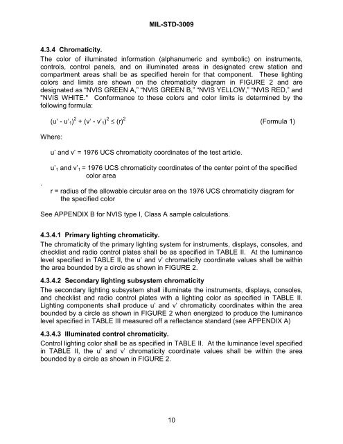
4.3.4 Chromaticity.<br />
The color of illuminated information (alphanumeric and symbolic) on instruments,<br />
controls, control panels, and on illuminated areas in designated crew station and<br />
compartment areas shall be as specified herein for that component. These <strong>lighting</strong><br />
colors and limits are shown on the chromaticity diagram in FIGURE 2 and are<br />
designated as “NVIS GREEN A,” “NVIS GREEN B,” “NVIS YELLOW,” “NVIS RED,” and<br />
"NVIS WHITE." Conformance to these colors and color limits is determined by the<br />
following formula:<br />
(u’ - u’1) 2 + (v’ - v’1) 2 ≤ (r) 2 (Formula 1)<br />
Where:<br />
.<br />
u’ and v’ = 1976 UCS chromaticity coordinates of the test article.<br />
u’1 and v’1 = 1976 UCS chromaticity coordinates of the center point of the specified<br />
color area<br />
r = radius of the allowable circular area on the 1976 UCS chromaticity diagram for<br />
the specified color<br />
See APPENDIX B for NVIS type I, Class A sample calculations.<br />
4.3.4.1 Primary <strong>lighting</strong> chromaticity.<br />
The chromaticity of the primary <strong>lighting</strong> <strong>system</strong> for instruments, displays, consoles, and<br />
checklist and radio control plates shall be as specified in TABLE II. At the luminance<br />
level specified in TABLE II, the u’ and v’ chromaticity coordinate values shall be within<br />
the area bounded by a circle as shown in FIGURE 2.<br />
4.3.4.2 Secondary <strong>lighting</strong> sub<strong>system</strong> chromaticity<br />
The secondary <strong>lighting</strong> sub<strong>system</strong> shall illuminate the instruments, displays, consoles,<br />
and checklist and radio control plates with a <strong>lighting</strong> color as specified in TABLE II.<br />
Lighting components shall produce u’ and v’ chromaticity coordinates within the area<br />
bounded by a circle as shown in FIGURE 2 when energized to produce the luminance<br />
level specified in TABLE III measured off a reflectance standard (see APPENDIX A)<br />
4.3.4.3 Illuminated control chromaticity.<br />
Control <strong>lighting</strong> color shall be as specified in TABLE II. At the luminance level specified<br />
in TABLE II, the u’ and v’ chromaticity coordinate values shall be within the area<br />
bounded by a circle as shown in FIGURE 2.<br />
10


