lighting, aircraft, night vision imaging system - General Dynamics ...
lighting, aircraft, night vision imaging system - General Dynamics ...
lighting, aircraft, night vision imaging system - General Dynamics ...

You also want an ePaper? Increase the reach of your titles
YUMPU automatically turns print PDFs into web optimized ePapers that Google loves.
DEPARTMENT OF DEFENSE<br />
INTERFACE STANDARD<br />
LIGHTING, AIRCRAFT,<br />
METRIC<br />
MIL-STD-3009<br />
2 February 2001<br />
SUPERSEDING<br />
MIL-L-85762A<br />
NIGHT VISION IMAGING SYSTEM<br />
(NVIS) COMPATIBLE<br />
AMSC: N/A AREA: GDRQ<br />
DISTRIBUTION STATEMENT A. Approved for public release; distribution is unlimited.
MIL-STD-3009<br />
FOREWORD<br />
1. MIL-L-85762A was published in 1988 and served very well for eleven years as the<br />
standard definition and interface criteria for NVIS compatibility. This new document<br />
(MIL-STD-3009) was derived from MIL-L-85762A as a way to preserve this widely<br />
accepted standard definition, and to comply with the Perry directive. In compliance<br />
with the Perry directive, this document no longer contains the <strong>lighting</strong> <strong>system</strong> design<br />
requirements that were in MIL-L-85762; it now deals only with interface and<br />
performance requirements.<br />
2. It is assumed that any contract for <strong>lighting</strong> equipment includes a Technical<br />
Requirements Document (TRD) (or similar document) that specifies the operational<br />
features of the <strong>lighting</strong> equipment. Such a TRD should reference this standard as<br />
the NVIS compatibility requirement when full compatibility between a specific class<br />
of NVIS and an <strong>aircraft</strong> is intended. The <strong>system</strong> specification requirements of an<br />
<strong>aircraft</strong> <strong>lighting</strong> <strong>system</strong> must be derived from other documents, after tailoring, such<br />
as JSSG-2010-5.<br />
3. This document maintains exactly the same technical criteria for Class A and Class B<br />
NVIS compatibility as was required by MIL-L-85762. It also adds discussion of<br />
Class C NVIS (colloquially known as “leaky green”). Class C NVIS are generally<br />
compatible with crewstation <strong>lighting</strong> that is class B compliant, so there are not yet<br />
any unique requirements for class C compatibility. This standard also adds exterior<br />
<strong>lighting</strong> compatibility definitions and criteria.<br />
4. Besides the original APPENDIX A and APPENDIX B, this document adds a third<br />
appendix (APPENDIX C), which provides rationale to explain the requirements in<br />
this standard and was derived from a technical report originally published by the<br />
Navy.<br />
5. Beneficial comments (recommendations, additions, and deletions) and any pertinent<br />
data which may be of use in improving this document should be addressed to<br />
ASC/ENFC, 2530 Loop Road West, Wright-Patterson AFB OH 45433-7101.<br />
ii
MIL-STD-3009<br />
CONTENTS<br />
Paragraph Page<br />
LIGHTING, AIRCRAFT, NIGHT VISION IMAGING SYSTEM (NVIS) COMPATIBLE .....1<br />
1. SCOPE...... ................ ...............................................................................................1<br />
1.1 Scope....................................................................................................................1<br />
1.2 Purpose. ...............................................................................................................1<br />
1.3 Classification.........................................................................................................1<br />
2. APPLICABLE DOCUMENTS .....................................................................................2<br />
2.1 <strong>General</strong>. ................................................................................................................2<br />
2.2 Government documents........................................................................................2<br />
2.2.1 Specifications, standards, and handbooks........................................................2<br />
2.2.2 Other Government publications. .......................................................................3<br />
2.3 Order of precedence.............................................................................................3<br />
3. DEFINITIONS............. ...............................................................................................4<br />
3.1 Night Vision Imaging System (NVIS).................................................................4<br />
3.2 NVIS <strong>lighting</strong> compatibility................................................................................4<br />
3.3 Lighting <strong>system</strong>. ................................................................................................5<br />
3.4 Lighting sub<strong>system</strong>............................................................................................5<br />
3.5 Crewstation or compartment. ............................................................................5<br />
3.6 Interior <strong>lighting</strong>...................................................................................................5<br />
3.7 CIE color coordinate <strong>system</strong>. ............................................................................6<br />
3.8 NVIS radiance. ..................................................................................................6<br />
3.9 Rated drive condition.........................................................................................6<br />
3.10 Light leaks. ......................................................................................................6<br />
3.11 Contrast vs contrast ratio. ...............................................................................6<br />
3.12 Electronic and/or electro-optical displays. .......................................................6<br />
3.13 IR mode...........................................................................................................6<br />
4. REQUIREMENTS....... ...............................................................................................7<br />
4.1. Description...........................................................................................................7<br />
4.2 System integration. ...............................................................................................8<br />
4.2.1 Lighting pro<strong>vision</strong>s..........................................................................................8<br />
4.2.2 Compartment <strong>lighting</strong>. ....................................................................................8<br />
4.2.3 Emergency exit <strong>lighting</strong>..................................................................................8<br />
4.2.4 Crewstation controls and control handles......................................................9<br />
4.2.5 Caution and advisory signals.........................................................................9<br />
4.2.6 Jump lights. ...................................................................................................9<br />
4.2.7 Work and inspection lights. ............................................................................9<br />
4.2.8 Map and utility lights.......................................................................................9<br />
4.3 Performance. ........................................................................................................9<br />
4.3.1 Daylight legibility and readability. ...................................................................9<br />
4.3.2 Night operations. ............................................................................................9<br />
4.3.3 Luminance and illuminance. ..........................................................................9<br />
4.3.4 Chromaticity. ................................................................................................10<br />
4.3.5 Spectral radiance limits. ...............................................................................16<br />
4.3.5.1 Primary <strong>lighting</strong> radiance...........................................................................16<br />
iii
MIL-STD-3009<br />
CONTENTS – Continued.<br />
Paragraph Page<br />
4.3.6 Light leaks. ...................................................................................................18<br />
4.3.7 Luminance uniformity. ..................................................................................18<br />
4.3.8 Crewstation reflections. ................................................................................18<br />
4.4 Luminance balance.............................................................................................18<br />
4.5 Exterior <strong>lighting</strong> sub<strong>system</strong>s. ..............................................................................18<br />
4.5.1 Anticollision <strong>lighting</strong>. .....................................................................................18<br />
4.5.2 Position lights. .............................................................................................18<br />
4.5.3 Tanker boom marker and nozzle illumination. .............................................19<br />
4.5.4 Formation lights............................................................................................19<br />
5. VERIFICATION .......... .............................................................................................20<br />
5.1 System level verification. ....................................................................................20<br />
5.2 Inspection conditions. .........................................................................................20<br />
5.3 Order of inspection. .............................................................................................20<br />
5.4 Lighting conditions. ............................................................................................20<br />
5.5 Test set up verification........................................................................................21<br />
5.6 Test set up. .........................................................................................................21<br />
5.7 Inspection methods and procedures...................................................................21<br />
5.7.1 Lighting <strong>system</strong> unaided eye inspection.......................................................21<br />
5.7.2 Lighting <strong>system</strong> NVIS compatible examination............................................21<br />
5.7.3 Luminance uniformity. .................................................................................22<br />
5.7.4 Crewstation reflections. ................................................................................22<br />
5.7.5 Visual examination. ......................................................................................22<br />
5.7.6 Operation.....................................................................................................22<br />
5.7.7 Environmental operating tests. ....................................................................23<br />
5.7.8 Electromagnetic interference (EMI) tests.....................................................23<br />
5.7.9 Electromagnetic compatibility (EMC) tests. ..................................................23<br />
5.7.10 Luminance and illuminance measurements. ..............................................23<br />
5.7.11 Chromaticity measurements.......................................................................24<br />
5.7.12 Spectral radiance measurements...............................................................27<br />
5.7.13 Light leak inspection...................................................................................33<br />
5.8 Exterior <strong>lighting</strong> verification. ................................................................................33<br />
5.8.1 Anticollision <strong>lighting</strong> verification....................................................................33<br />
5.8.2 Position lights verification. ...........................................................................33<br />
5.8.3 Tanker boom marker and nozzle illumination verification............................33<br />
5.8.4 Formation lights verification.........................................................................34<br />
6. NOTES ...... ................ .............................................................................................35<br />
6.1 Intended use. ......................................................................................................35<br />
6.2 Issue of DODISS. ...............................................................................................35<br />
6.3 International standardization...............................................................................35<br />
6.4 Rationale.............................................................................................................35<br />
6.5 Subject term (keyword) listing.............................................................................35<br />
6.6 Metrication. .........................................................................................................36<br />
iv
MIL-STD-3009<br />
CONTENTS – Continued.<br />
Paragraph Page<br />
APPENDIX A: SPECTRAL RADIANCE, LUMINANCE, AND ILLUMINANCE<br />
MEASURING EQUIPMENT ..................................................................37<br />
A.1 SCOPE ... ................ .............................................................................................37<br />
A.1.1 Scope. .............................................................................................................37<br />
A.2 APPLICABLE DOCUMENTS .................................................................................37<br />
A.3 SPECTRORADIOMETER......................................................................................37<br />
A.3.1 Chromaticity and spectral radiance measurement. .........................................37<br />
A.3.2 Spectroradiometer sensitivity. ..........................................................................37<br />
A.3.2.1 Spectroradiometer sensitivity calibration...................................................38<br />
A.3.3 Wavelength accuracy and repeatability...........................................................38<br />
A.3.3.1 Wavelength accuracy and repeatability verification. .................................38<br />
A.3.4 Current resolution............................................................................................39<br />
A.3.5 Zero drift. .........................................................................................................39<br />
A.3.6 Linearity...........................................................................................................39<br />
A.3.6.1 Linearity verification. .................................................................................39<br />
A.3.7 Signal conditioning. .........................................................................................40<br />
A.3.8 Stray light.........................................................................................................40<br />
A.3.8.1 Stray light verification................................................................................40<br />
A.3.9 Spectroradiometer optics.................................................................................40<br />
A.3.10 Spectroradiometer viewing <strong>system</strong>................................................................40<br />
A.3.10.1 Spectroradiometer viewing verification. ..................................................41<br />
A.3.11 Spectroradiometer accuracy..........................................................................41<br />
A.3.11.1 Spectroradiometer accuracy verification.................................................41<br />
A.4 PHOTOMETER........ .............................................................................................41<br />
A.4.1 Luminance measurement equipment. .............................................................41<br />
A.4.2 Photometer calibration.....................................................................................42<br />
A.4.2.1 Photometer sensitivity...............................................................................42<br />
A.4.2.2 Photometer accuracy. ...............................................................................42<br />
A.4.2.3 Photometer sensitivity and accuracy verification. .....................................42<br />
A.4.3 Readout resolution. .........................................................................................42<br />
A.4.4 Photometer optics. ..........................................................................................42<br />
A.4.5 Photometer viewing <strong>system</strong>.............................................................................42<br />
A.4.5.1 Photometer viewing <strong>system</strong> verification. ...................................................43<br />
A.4.6 Photometer polarization error. .........................................................................43<br />
A.4.6.1 Photometer polarization error verification. ................................................43<br />
A.4.7 Colorimetry. .....................................................................................................43<br />
A.5 REFLECTANCE STANDARD ................................................................................44<br />
A.5.1 Reflectance standard. .....................................................................................44<br />
A.5.1.1 Reflectance standard verification..............................................................44<br />
A.6 NOTES.... ................ .............................................................................................44<br />
A.6.1 Filter. ..............................................................................................................44<br />
v
MIL-STD-3009<br />
CONTENTS – Continued.<br />
Paragraph Page<br />
APPENDIX B: SAMPLE CALCULATIONS...................................................................45<br />
B.1 SCOPE ... ................ .............................................................................................45<br />
B.1.1 Scope. .............................................................................................................45<br />
B.2 APPLICABLE DOCUMENTS .................................................................................45<br />
B.3 NVIS RADIANCE CALCULATIONS.......................................................................45<br />
B.4 CHROMATICITY CALCULATIONS .......................................................................46<br />
APPENDIX C: RATIONALE BEHIND THE REQUIREMENTS CONTAINED IN<br />
LIGHTING, AIRCRAFT, INTERIOR, NIGHT VISION IMAGING<br />
SYSTEM (NVIS) COMPATIBLE............................................................52<br />
C.1. SCOPE .. ................ .............................................................................................52<br />
C.1.1 Scope. .............................................................................................................52<br />
C.2. APPLICABLE DOCUMENTS................................................................................52<br />
C.3. RATIONALE FOR THIS DOCUMENT ..................................................................52<br />
C.3.2 Summary.........................................................................................................52<br />
C.3.3 Background. ....................................................................................................53<br />
C.3.4 NVIS background. ...........................................................................................53<br />
C.4. DISCUSSION.......... .............................................................................................56<br />
C.4.1 Interactions.......................................................................................................56<br />
C.4.2 Classification. ..................................................................................................57<br />
C.5. REQUIREMENTS ... .............................................................................................63<br />
C.5.1 NVIS sensitivity characteristics........................................................................63<br />
C.5.2 Mockup............................................................................................................63<br />
C.5.3 Light sources...................................................................................................63<br />
C.5.4 Compartment <strong>lighting</strong>. .....................................................................................64<br />
C.5.5 Emergency exit <strong>lighting</strong>. ..................................................................................64<br />
C.5.6 Jump lights. .....................................................................................................64<br />
C.5.7 Work, map, and inspection lights. ...................................................................64<br />
C.5.8 Daylight legibility and readability. ....................................................................64<br />
C.5.9 Daylight legibility and readability of illuminated visual signals. ........................65<br />
C.5.10 Daylight legibility and readability of electronic and electro-optical displays....65<br />
C.5.11 Minimum contrast requirements. ...................................................................66<br />
C.5.12 Compensation multipliers. .............................................................................66<br />
C.5.13 Minimum difference luminance......................................................................67<br />
C.6. CHROMATICITY..... .............................................................................................67<br />
C.6.1 Background of chromaticity requirements. .......................................................67<br />
C.6.2 Utility lights, work, inspection light, and compartment light chromaticity. ........70<br />
C.6.3 Caution, advisory, warning and master caution lights chromaticity. ................70<br />
C.7. SPECTRAL RADIANCE LIMITS...........................................................................71<br />
C.7.1 Background of spectral radiance limits............................................................71<br />
C.7.2 Monochromatic display radiance.....................................................................76<br />
C.7.3 Multi-color display radiance.............................................................................76<br />
C.7.4 Warning and master caution signal and emergency exit <strong>lighting</strong> radiance......77<br />
C.7.5 Jump light radiance. ........................................................................................78<br />
vi
MIL-STD-3009<br />
CONTENTS – Continued.<br />
Paragraph Page<br />
C.7.6 Head up display (HUD) <strong>system</strong> radiance. .......................................................78<br />
C.7.8 Light leaks. ......................................................................................................79<br />
C.7.9 Luminance uniformity. .....................................................................................79<br />
C.7.10 Maintenance trimming controls (MIL-L-85762 only); now called Luminance<br />
balance. .....................................................................................................................79<br />
C.7.11 Verification (quality assurance pro<strong>vision</strong>s in MIL-L-85762). ..........................79<br />
C.7.11.1 Lighting conditions. .................................................................................80<br />
C.7.11.2 Lighting <strong>system</strong> NVIS compatibility examination. ...................................80<br />
C.7.11.3 Chromaticity measurements. ..................................................................80<br />
C.7.11.4 Spectral radiance measurements. .........................................................80<br />
C.7.11.5 Light leak inspection. ..............................................................................81<br />
C.7.11.6 Daylight legibility and readability inspection (no longer included in the<br />
standard). ...............................................................................................................82<br />
C.7.12 Additional information....................................................................................82<br />
C.7.12.1 Rationale for spectroradiometer requirements........................................84<br />
C.7.12.2 Rationale for photometer requirements. .................................................84<br />
C.8. SUMMARY AND CONCLUSIONS........................................................................84<br />
C.9. REFERENCES ....... .............................................................................................85<br />
TABLES<br />
TABLE I. <strong>General</strong> <strong>lighting</strong> for crew stations and compartments. *.................................8<br />
TABLE II. Chromaticity requirements. ..........................................................................13<br />
Table III. NVIS radiance requirements (metric units)....................................................14<br />
TABLE III.a. NVIS radiance requirements using English units. ....................................15<br />
TABLE IV. Relative spectral response of Class A NVIS (GA(λ))...................................30<br />
TABLE V. Relative spectral response of Class B NVIS (GB(λ))...................................31<br />
FIGURES<br />
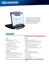
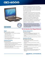
FIGURE 1. Relative spectral response characteristics of Classes A, B, and C NVIS. ...7<br />
FIGURE 2. NVIS <strong>lighting</strong> color limits. ...........................................................................11<br />
FIGURE B-1. Spectral output of example signal at rated drive conditions<br />
(6.1108 cd/m2) (1.7839fL) - Continued...................................................49<br />
FIGURE B-2. Spectral output of example signal at 0.343 cd/m 2 (0.I fL).......................50<br />
FIGURE B-2. Spectral output of example signal at 0.343 cd/m 2 (0.I fL) - Continued. ..51<br />
FIGURE C-1. Diagram of an image intensifier. ............................................................54<br />
FIGURE C-2. Conceptual diagram of the spectral distribution of NVIS-compatible<br />
<strong>lighting</strong>. ... .............................................................................................55<br />
FIGURE C-3. NVIS interfaces. .....................................................................................56<br />
FIGURE C-4. Spectral transmission requirements for a Class A NVIS objective lens. 60<br />
FIGURE C-5. Spectral transmission requirements for a Class B NVIS objective lens. 61<br />
vii
MIL-STD-3009<br />
CONTENTS – Continued.<br />
Paragraph Page<br />
FIGURE C-6. Spectral transmission requirements for a Class C NVIS objective lens. 62<br />
FIGURE C-7. “Optimum” and “poor” theoretical spectral distributions. ........................73<br />
FIGURE C-8. ................. Normalized spectral sensitivity curve for a third-generation<br />
image<br />
intensifier tube. .......................................................................................82<br />
FIGURE C-9. Spectral distribution of starlight. .............................................................83<br />
FIGURE C-10. Spectral reflectivity of tree bark............................................................83<br />
viii
MIL-STD-3009<br />
LIGHTING, AIRCRAFT, NIGHT VISION<br />
IMAGING SYSTEM (NVIS) COMPATIBLE<br />
This document is approved for use by the Department of the Air Force and is available<br />
for use by all Departments and Agencies of the Department of Defense.<br />
1. SCOPE<br />
1.1 Scope.<br />
This standard establishes requirements for the emission characteristics of <strong>aircraft</strong><br />
<strong>lighting</strong> and display equipment that is intended for use with <strong>night</strong> <strong>vision</strong> <strong>imaging</strong> <strong>system</strong>s<br />
(NVIS). It is applicable to all <strong>system</strong>s, sub<strong>system</strong>s, component equipment, and<br />
hardware that provide the <strong>lighting</strong> environment on <strong>aircraft</strong> where NVIS are employed.<br />
This document is applicable to NVIS specific performance requirements but it does not<br />
contain general <strong>lighting</strong> requirements. The contracting activity should extract and tailor<br />
applicable general <strong>lighting</strong> requirements from JSSG-2010-5 and include those<br />
requirements in the contract.<br />
1.2 Purpose.<br />
The purpose of this document is to provide interface requirements and testing<br />
methodology to ensure compatible and standardized <strong>aircraft</strong> interior <strong>lighting</strong> for NVIS<br />
compatibility.<br />
1.3 Classification.<br />
Night <strong>vision</strong> <strong>imaging</strong> <strong>system</strong> (NVIS) compatible <strong>aircraft</strong> interior <strong>lighting</strong> is divided into the<br />
following types and classes.<br />
Type I Lighting compatible with any direct view image NVIS (see 3.1.1)<br />
utilizing Generation III image intensifier tubes.<br />
Type II Lighting compatible with any projected image NVIS (see 3.1.2)<br />
utilizing Generation III image intensifier tubes.<br />
Class A Lighting compatible with NVIS utilizing 625 nm minus blue<br />
objective lens filters (see 3.1.3) with the specifications in<br />
FIGURE 1.<br />
Class B Lighting compatible with NVIS utilizing 665 nm minus blue<br />
objective lens filters (see 3.1.4) with the specifications in<br />
FIGURE 1.<br />
1
MIL-STD-3009<br />
Class C Lighting compatible with NVIS having a "green leak" as shown<br />
in FIGURE 1. This edition of this document assumes that<br />
<strong>lighting</strong> meeting class B compatibility criteria is also compatible<br />
with Class C NVIS.<br />
2. APPLICABLE DOCUMENTS<br />
2.1 <strong>General</strong>.<br />
The documents listed in this section are specified in sections 4 and 5 of this document.<br />
This section does not include documents cited in other sections of this document or<br />
recommended for additional information or as examples. While every effort has been<br />
made to ensure the completeness of this list, document users are cautioned that they<br />
must meet all specified requirements documents cited in sections 4 and 5 of this<br />
document, whether or not they are listed.<br />
2.2 Government documents.<br />
2.2.1 Specifications, standards, and handbooks.<br />
The following specifications, standards, and handbooks form a part of this document to<br />
the extent specified herein. Unless otherwise specified, the issues of these documents<br />
are those listed in the issue of the Department of Defense Index of Specifications and<br />
Standards (DoDISS) and supplement thereto, cited in the solicitation (see 6.2).<br />
HANDBOOKS<br />
DEPARTMENT OF DEFENSE<br />
JSSG-2010-3 Joint Service Specification Guide – Crew Systems –<br />
Cockpit/Crew Station/Cabin Handbook<br />
JSSG-2010-5 Joint Service Specification Guide – Crew Systems – Aircraft<br />
Lighting Handbook<br />
JSSG documents can be obtained from ASC/ENOI, Bldg 560, 2530 Loop Road West,<br />
Wright-Patterson AFB OH 45433-7101<br />
MIL-HDBK-87213 Electronically/Optically Generated Airborne Displays<br />
(Unless otherwise indicated, copies of the above specifications, standards, and<br />
handbooks are available from the Standardization Documents Order Desk, 700<br />
Robbins Avenue, Building 4D, Philadelphia, PA 19111-5094.) (Copies of those<br />
documents indicated with a distribution limitation may be obtained from ASC/ENOI,<br />
2530 Loop Rd West, Bldg. 560, Wright-Patterson AFB, OH 45433-7101. Telephone<br />
(937) 255-6296; DSN 785-6296.)<br />
2
MIL-STD-3009<br />
2.2.2 Other Government publications.<br />
The following other Government publications form a part of this standard to the extent<br />
specified herein. Unless otherwise specified, the issues are those cited in the<br />
solicitation (see 6.2).<br />
TITLE 14 CODE OF FEDERAL REGULATIONS<br />
FAR Part 23 - Airworthiness Standards: Normal, Utility, Acrobatic, and<br />
Commuter Category Airplanes<br />
FAR Part 25 - Airworthiness Standards: Transport Category Airplanes<br />
(Copies of Federal Aviation Administration Regulations may be viewed at<br />
http://www.faa.gov/avr/AFS/FARS/, or may be obtained from the Federal Aviation<br />
Administration, 800 Independence Ave., SW, Washington, DC 20591.)<br />
2.3 Order of precedence.<br />
In the event of a conflict between the text of this document and the references cited<br />
herein, the text of this document takes precedence. Nothing in this document,<br />
however, supersedes applicable laws and regulations unless a specific exemption has<br />
been obtained.<br />
3
3. DEFINITIONS<br />
MIL-STD-3009<br />
3.1 Night Vision Imaging System (NVIS).<br />
A <strong>system</strong> that uses image intensifier tubes to produce an enhanced image of a scene in<br />
light conditions too low for normal navigation and pilotage.<br />
3.1.1 Direct View Image NVIS (Type I).<br />
Any NVIS that uses generation III image intensifier tubes and displays the intensified<br />
image on a phosphor screen in the user’s direct line of sight.<br />
3.1.2 Projected Image NVIS (Type II).<br />
Any NVIS that uses generation III, image intensifier tubes and projects the intensified<br />
image on a see through medium in the user’s line of sight. This configuration allows<br />
simultaneous viewing of the intensified image and visual cues such as HUD symbology.<br />
3.1.3 Class A NVIS.<br />
Any NVIS with characteristics as shown in FIGURE 1. Class A NVIS is not compatible<br />
with red cockpit lights because of the overlap between the spectrum of red light and the<br />
sensitivity of Class A NVIS.<br />
3.1.4 Class B NVIS.<br />
Any NVIS with characteristics as shown in FIGURE 1. A Class B NVIS is compatible<br />
with NVIS Red and therefore is compatible with properly filtered red lights and color<br />
electronic displays that meet the requirements of TABLE II and TABLE III. When<br />
specified in TABLE III, certain components are required to meet Class A NVIS<br />
compatibility requirements in order to facilitate interchangeability of equipment.<br />
3.1.5 Class C NVIS.<br />
Some <strong>aircraft</strong> have HUDs that use a hologram as the reflective element in the<br />
combining glass. Holograms typically work with only one wavelength of light. This<br />
feature can be used to improve the efficiency and see-through clarity of the HUD, but it<br />
means the light coming from the HUD is concentrated at one wavelength. Since this<br />
wavelength is in the green part of the spectrum and is blocked by the minus blue filter in<br />
the NVIS, it is nearly impossible to see a holograph HUD with Class A or B NVIS.<br />
Consequently, modified NVIS have been built and tested which have a “notch” or “leak”<br />
in the green part of the spectrum. The Class C filter is sometimes called the “leaky<br />
green” filter. See the spectral plots of Class A, B, C that are shown in FIGURE 1 and<br />
the requirements for Class C NVIS FIGURE C-6 at APPENDIX C.<br />
3.2 NVIS <strong>lighting</strong> compatibility<br />
3.2.1 Compatible interior <strong>lighting</strong>.<br />
The <strong>aircraft</strong> interior <strong>lighting</strong> that provides acquisition of <strong>aircraft</strong> interior information with<br />
the unaided eye without degrading the image intensification capabilities of the NVIS<br />
during <strong>night</strong> flight operations. Conforming to the detailed performance and test<br />
requirements specified herein shall be considered as meeting this definition.<br />
4
MIL-STD-3009<br />
3.2.2 Secure.<br />
An Army definition, often applied to ground vehicles and equipment, meaning that the<br />
visible light emitted is reduced to the minimum needed to do the mission, and the near<br />
IR content is reduced to less than an estimated 5% of the visible light.<br />
3.2.3 Friendly.<br />
Exterior <strong>lighting</strong> that is fully usable by people without NVIS (i.e., typically meets FAA<br />
requirements for visibility and chromaticity) but has drastically reduced IR content so<br />
that it can be used while flying formation with <strong>aircraft</strong> in which NVIS are being used (for<br />
example, going to and from a training site through civilian airspace).<br />
3.2.4 Covert.<br />
IR lights or lights that are typically filtered so they are not visible to the naked eye<br />
beyond approximately 20 to 30 feet. These lights may be intended to provide<br />
illumination so that NVIS will work without adequate natural light.<br />
3.3 Lighting <strong>system</strong>.<br />
All devices that emit or transmit light within the flight deck or other crew compartments.<br />
3.4 Lighting sub<strong>system</strong>.<br />
All devices that emit or transmit light within the flight deck or other crew compartments<br />
and are attached to the <strong>aircraft</strong> power via a common dimmer control.<br />
3.5 Crewstation or compartment.<br />
All work stations or compartments within the <strong>aircraft</strong> in which the air crewmember is<br />
required to use NVIS in the performance of duties.<br />
3.6 Interior <strong>lighting</strong>.<br />
All <strong>lighting</strong> within the <strong>aircraft</strong> including but not restricted to the following <strong>lighting</strong><br />
<strong>system</strong>s:<br />
a. Instrument<br />
• Primary<br />
• Secondary<br />
b. Console<br />
• Primary<br />
• Secondary<br />
c. Emergency<br />
d. Warning, caution, and advisory displays and indicators<br />
e. Utility<br />
f. Controls (knobs, handles, push buttons)<br />
g. Compartment<br />
h. Work and inspection lights<br />
i. Jump lights<br />
5
MIL-STD-3009<br />
3.7 CIE color coordinate <strong>system</strong>.<br />
The fundamental definitions of color are expressed in terms of the “standard observer”<br />
and coordinate <strong>system</strong> adopted by the International Commission on Illumination (C.I.E.)<br />
at Cambridge, England, in 1931 and published in the Journal of the Optical Society of<br />
America, Vol. 23, page 359, October 1933. Wherever chromaticity coordinates (x, y, z)<br />
appear in this document, they relate to this <strong>system</strong>. The CIE 1976 uniform chromaticity<br />
scale (UCS) diagram is the CIE 1931 chromaticity diagram redrawn with the x and y<br />
axes subjected to a linear transformation as defined in CIE Publication 15, Supplement<br />
2, 1978.<br />
3.8 NVIS radiance.<br />
NVIS radiance is the amount of energy emitted by a light source that is visible through<br />
NVIS. NVIS radiance is defined as the integral of the curve generated by multiplying<br />
the spectral radiance of a light source by the relative spectral response of the NVIS<br />
defined in TABLE III or TABLE III.a, as appropriate.<br />
3.9 Rated drive condition.<br />
Rated drive condition(s) are the electrical power state(s) obtained by conformance to<br />
the allowable electrical characteristics (voltage, current, pulse width modulation,<br />
frequency, etc.) in MIL-STD-704 for the various <strong>lighting</strong> components or <strong>system</strong>s in<br />
meeting specified <strong>lighting</strong> levels.<br />
3.10 Light leaks.<br />
Visual evidence through the NVIS of light emitted from a component from areas that are<br />
not intended to be illuminated (non-compatible unfiltered light leaks).<br />
3.11 Contrast vs. contrast ratio.<br />
Contrast (CL, CI and CUL), as specified in this document, is one less than contrast ratio,<br />
which is defined as L2/L1 in some specifications.<br />
3.12 Electronic and/or electro-optical displays.<br />
All displays capable of presenting a variety of different images on their screen; the<br />
displayed portrayals being generated through direct electronic modulation or through<br />
indirect electro-optical modulation of emitted, transmitted, or reflected light luminance<br />
levels, contrasts, and/or chromaticities. These displays may present characters,<br />
numerals, symbols, graphics, or video. They are based on a CRT, a dot matrix<br />
technology, or a segmented design, and may, or may not be, capable of portraying<br />
shades of gray.<br />
3.13 IR mode.<br />
The infrared (IR) or covert mode for exterior <strong>lighting</strong> is defined as not viewable by a<br />
dark-adapted, unaided eye at a distance greater than 30 feet, in the dark (i.e., less than<br />
1.0 footcandle ambient illumination), and when the <strong>system</strong> is on the ground. The mode<br />
shall be viewable by NVIS at minimum distance of 3 NM in the air, at <strong>night</strong>, with a ¾ to<br />
full moon, and with all other <strong>system</strong> exterior lights off. “Lower hemisphere” shall be<br />
defined as not viewable by an NVIS equipped ground or aerial observer when the<br />
<strong>system</strong> is directly overhead, straight and level, and at 300 to 500 feet away.<br />
6
4. REQUIREMENTS<br />
MIL-STD-3009<br />
4.1. Description<br />
This document defines the radiant energy interface requirements and test procedures<br />
applicable to NVIS compatible <strong>lighting</strong> <strong>system</strong>s for new or modified <strong>aircraft</strong> <strong>lighting</strong><br />
equipment and crew stations. FIGURE 1 is the assumed NVIS spectral response<br />
characteristics that shall be used to define NVIS compatibility criteria herein.<br />
Relative<br />
Response<br />
1.0E+00<br />
1.0E-01<br />
1.0E-02<br />
1.0E-03<br />
1.0E-04<br />
1.0E-05<br />
450<br />
480<br />
510<br />
540<br />
570<br />
600<br />
630<br />
660<br />
690<br />
720<br />
750<br />
780<br />
810<br />
840<br />
870<br />
900<br />
930<br />
nanometers<br />
7<br />
NVIS-A<br />
NVIS-B<br />
NVIS-C<br />
FIGURE 1. Relative spectral response characteristics of Classes A, B, and C NVIS.
MIL-STD-3009<br />
4.2 System integration.<br />
The design of the <strong>lighting</strong> equipment shall not interfere with the operation of the <strong>system</strong><br />
at <strong>night</strong>, with or without NVIS, or during the daytime.<br />
4.2.1 Lighting pro<strong>vision</strong>s.<br />
The design and location of the <strong>lighting</strong> equipment shall optimize visual performance and<br />
minimize the effects on NVIS. The lights shall not cause direct or indirect glare or<br />
interfere with the aircrew member’s interior or exterior unaided <strong>vision</strong> and with the<br />
image intensification capabilities of the NVIS.<br />
4.2.2 Compartment <strong>lighting</strong>.<br />
Illuminance levels shall be as required by TABLE I, unless otherwise specified by the<br />
acquiring activity. Chromaticity and spectral radiance limits shall be as specified in<br />
TABLE II and TABLE III, respectively.<br />
TABLE I. <strong>General</strong> <strong>lighting</strong> for crew stations and compartments. *<br />
CREWSTATION AREA, GENERAL ILLUMINATION<br />
CONTROL PANELS NOT ILLUMINATED<br />
(REQUIRING IN-FLIGHT ADJUSTMENT AND<br />
8<br />
ILLUMINATED LEVEL IN LUX<br />
AND (FOOT CANDLES) AT<br />
RATED DRIVE CONDITION<br />
MIN MAX<br />
10.8 (1)<br />
(Aisle<br />
floor)<br />
215 (20)<br />
(Crew lap<br />
level)<br />
54 (5) 108 (10)<br />
OPERATION)<br />
INSTRUMENT PANEL AND CONSOLES 21.5 (2) 108 (10)<br />
PASSAGEWAYS AND AISLES (ON FLOOR) 2.15 (0.2) 54 (5)<br />
CARGO COMPARTMENT (ON FLOOR) 2.15 (0.2) 54 (5)<br />
LOADING AND RAMP AREAS (ON FLOOR) 21.5 (2) 10.8 (10)<br />
CREWSTATION LOCATIONS FOR NAVIGATIONAL<br />
AND SYSTEMS COMPUTATIONS TASKS<br />
(LIGHT ON WORK AREAS)<br />
323 (30) 646 (60)<br />
AUXILIARY POWER PLANT, ELECTRICAL AND<br />
ELECTRONIC COMPARTMENTS<br />
(LIGHT ON WORK AREAS)<br />
54 (5) 108 (10)<br />
* Continuous intensity control of the above <strong>lighting</strong> from full bright to 0.02% of full bright<br />
and “off” is required.<br />
4.2.3 Emergency exit <strong>lighting</strong>.<br />
Emergency exit <strong>lighting</strong> sub<strong>system</strong>s that may be automatically activated during flight<br />
shall meet the spectral radiance requirements in 4.3.5 and TABLE III.
MIL-STD-3009<br />
4.2.4 Crewstation controls and control handles.<br />
The lighted color and spectral radiance limits for illuminated controls shall be as<br />
specified in TABLE II and TABLE III.<br />
4.2.5 Caution and advisory signals.<br />
The location shall permit unaided eye viewing by an aviator wearing NVIS without<br />
extreme head movement. Chromaticity limits shall be as specified in TABLE II and the<br />
NVIS radiance requirements shall be as specified in TABLE III.<br />
4.2.6 Jump lights.<br />
The NVIS radiance of jump lights shall be as specified in TABLE III and chromaticity<br />
limits shall be as specified in TABLE II. Different geometric shapes and sizes as well<br />
as different colors may be used to distinguish the “caution light” from the “jump light”<br />
when viewed through the NVIS. The specific geometric shape designs shall be<br />
approved by the acquiring activity.<br />
4.2.7 Work and inspection lights.<br />
When provided as part of the <strong>aircraft</strong>, work and inspection lights shall meet the<br />
chromaticity and NVIS radiance limits specified in TABLE II and TABLE III.<br />
4.2.8 Map and utility lights.<br />
NVIS "White" shall be used for map lights. Map, chart, utility, or work lights shall meet<br />
the chromaticity and NVIS radiance limits specified in TABLE II and TABLE III.<br />
4.3 Performance.<br />
4.3.1 Daylight legibility and readability.<br />
Daytime legibility of <strong>lighting</strong> equipment is not specified by this standard. Criteria for<br />
legibility of <strong>lighting</strong> equipment in bright environments should be specified using the<br />
guidance in MIL-HDBK-87213 or JSSG-2010-5.<br />
4.3.2 Night operations.<br />
During <strong>night</strong> operations, the <strong>lighting</strong> <strong>system</strong> shall provide the aircrew members with a<br />
capability to rapidly and accurately obtain required crewstation information with unaided<br />
<strong>vision</strong>. The <strong>lighting</strong> <strong>system</strong> shall not have an adverse effect on external unaided <strong>night</strong><br />
<strong>vision</strong> or on the aircrew’s capability to obtain required information external to the <strong>aircraft</strong><br />
while employing NVIS.<br />
4.3.3 Luminance and illuminance.<br />
Unless otherwise specified, the levels of luminance or illuminance shall be as required<br />
in the applicable documents cited herein for each component, <strong>system</strong>, or sub<strong>system</strong>.<br />
The levels of luminance for those areas not covered in the applicable documents shall<br />
be in accordance with TABLE I.<br />
9
MIL-STD-3009<br />
4.3.4 Chromaticity.<br />
The color of illuminated information (alphanumeric and symbolic) on instruments,<br />
controls, control panels, and on illuminated areas in designated crew station and<br />
compartment areas shall be as specified herein for that component. These <strong>lighting</strong><br />
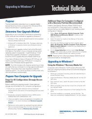
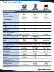
colors and limits are shown on the chromaticity diagram in FIGURE 2 and are<br />
designated as “NVIS GREEN A,” “NVIS GREEN B,” “NVIS YELLOW,” “NVIS RED,” and<br />
"NVIS WHITE." Conformance to these colors and color limits is determined by the<br />
following formula:<br />
(u’ - u’1) 2 + (v’ - v’1) 2 ≤ (r) 2 (Formula 1)<br />
Where:<br />
.<br />
u’ and v’ = 1976 UCS chromaticity coordinates of the test article.<br />
u’1 and v’1 = 1976 UCS chromaticity coordinates of the center point of the specified<br />
color area<br />
r = radius of the allowable circular area on the 1976 UCS chromaticity diagram for<br />
the specified color<br />
See APPENDIX B for NVIS type I, Class A sample calculations.<br />
4.3.4.1 Primary <strong>lighting</strong> chromaticity.<br />
The chromaticity of the primary <strong>lighting</strong> <strong>system</strong> for instruments, displays, consoles, and<br />
checklist and radio control plates shall be as specified in TABLE II. At the luminance<br />
level specified in TABLE II, the u’ and v’ chromaticity coordinate values shall be within<br />
the area bounded by a circle as shown in FIGURE 2.<br />
4.3.4.2 Secondary <strong>lighting</strong> sub<strong>system</strong> chromaticity<br />
The secondary <strong>lighting</strong> sub<strong>system</strong> shall illuminate the instruments, displays, consoles,<br />
and checklist and radio control plates with a <strong>lighting</strong> color as specified in TABLE II.<br />
Lighting components shall produce u’ and v’ chromaticity coordinates within the area<br />
bounded by a circle as shown in FIGURE 2 when energized to produce the luminance<br />
level specified in TABLE III measured off a reflectance standard (see APPENDIX A)<br />
4.3.4.3 Illuminated control chromaticity.<br />
Control <strong>lighting</strong> color shall be as specified in TABLE II. At the luminance level specified<br />
in TABLE II, the u’ and v’ chromaticity coordinate values shall be within the area<br />
bounded by a circle as shown in FIGURE 2.<br />
10
v'<br />
0.60<br />
0.50<br />
0.40<br />
0.30<br />
0.20<br />
0.10<br />
NVIS GREEN A<br />
u’ = .088<br />
v’ = .543<br />
r = .037<br />
NVIS GREEN B<br />
u’ = .131<br />
v’ = .623<br />
r = .057<br />
MIL-STD-3009<br />
11<br />
NVIS YELLOW<br />
u’ = .274<br />
v’ = .622<br />
r = .083<br />
0.00<br />
0.00 0.10 0.20 0.30 0.40 0.50 0.60<br />
u'<br />
CIE 1976 UCS Chromaticity Diagram<br />
FIGURE 2. NVIS <strong>lighting</strong> color limits.<br />
NVIS RED<br />
u’ = .450<br />
v’ = .550<br />
r = .060<br />
NVIS<br />
WHITE<br />
u’ = .190<br />
v’ = .49<br />
r = .04
MIL-STD-3009<br />
4.3.4.4 Compartment <strong>lighting</strong> chromaticity.<br />
Compartment <strong>lighting</strong> color shall be as specified in TABLE II. Lighting components<br />
shall produce u’ and v’ chromaticity coordinates within the area bounded by a circle as<br />
shown in FIGURE 2 when energized to produce the luminance level specified in TABLE<br />
II measured off a reflectance standard surface (see APPENDIX A).<br />
4.3.4.5 Utility, work, map, and inspection light chromaticity.<br />
The color of utility area, work area, map, and inspection <strong>lighting</strong> shall be white or green,<br />
as specified in the contract. Lighting components shall produce u’ and v’ chromaticity<br />
coordinates within the area bounded by a circle as shown in FIGURE 2 when energized<br />
to produce the luminance level specified in TABLE II measured off a reflectance<br />
standard surface (see APPENDIX A).<br />
4.3.4.6 Caution and advisory lights chromaticity.<br />
Caution and advisory <strong>lighting</strong> color shall be as specified in TABLE II. At the luminance<br />
level specified in TABLE II, the u’ and v’ chromaticity coordinate values shall be within<br />
the area bounded by a circle as shown in FIGURE 2.<br />
12
MIL-STD-3009<br />
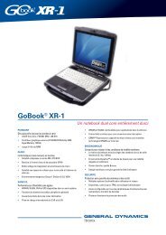
TABLE II. Chromaticity requirements.<br />
TYPE 1 TYPE II<br />
Class A Class B Class A Class B<br />
Lighting<br />
Para. u’1 v’1 r cd/m<br />
component(s)<br />
2<br />
NVIS u’1 v’1 r cd/m<br />
(fL) Color<br />
2<br />
NVIS u’1 v’1 r cd/m<br />
(fL) Color<br />
2<br />
NVIS u’1 v’1 r cd/m<br />
(fL) Color<br />
2 () NVIS<br />
Color<br />
Primary 4.3.4.1 .088 .543 .037 0.343 Green A .088 .543 .037 0.343 Green A<br />
(0.1)<br />
(0.1)<br />
Secondary 4.3.4.2 .088 .543 .037 0.343 Green A .088 .543 .037 0.343 Green A<br />
(0.1)<br />
(0.1)<br />
Illuminated controls 4.3.4.3 .088 .543 .037 0.343 Green A .088 .543 .037 0.343 Green A<br />
(0.1)<br />
(0.1)<br />
Compartment 4.3.4.4 .088 .543 .037 0.343 Green A Same .088 .543 .037 0.343 Green A Same<br />
<strong>lighting</strong><br />
(0.1)<br />
(0.1)<br />
Utility, map, work, 4.3.4.5 .088 .543 .037 0.343 Green A as .088 .543 .037 0.343 Green A as<br />
and inspection<br />
(0.1)<br />
(0.1)<br />
4.3.4.5 .190 .49 .04 0.343 White Class A .190 .49 .04 0.343 White Class A<br />
(0.1)<br />
(0.1)<br />
Caution and advisory<br />
signals<br />
Jump lights 4.3.4.7 .088<br />
Special <strong>lighting</strong><br />
components where<br />
increased display<br />
emphasis by highly<br />
saturated (monochromatic)<br />
color is<br />
necessary, or<br />
adequate display<br />
light readability<br />
cannot be achieved<br />
with “GREEN A”<br />
4.3.4.6 .088 .543 .037 0.343<br />
(0.1)<br />
All of the<br />
above<br />
.543 .037 17.2<br />
(5.0)<br />
.274 .622 .083 51.5<br />
(15.0)<br />
.131 .623 .057 0.343<br />
(0.1)<br />
Green A .088 .543 .037 0.343<br />
(0.1)<br />
13<br />
Green A<br />
Green A<br />
.088 .543 .037 17.2<br />
(5.0)<br />
Green A<br />
Yellow<br />
.274 .622 .083 51.5<br />
(15.0)<br />
Yellow<br />
Green B .131 .623 .057 0.1 Green B<br />
Warning signal 4.3.4.8.1 .274 .622 .083 51.5 Yellow .274 .622 .083 51.5 Yellow .274 .622 .083 51.5 Yellow .274 .622 .083 51.5 Yellow<br />
(15.0)<br />
(15.0)<br />
(15.0)<br />
(15.0)<br />
NOT APPLICABLE .450 .550 .060 51.5 Red NOT APPLICABLE .450 .550 .060 51.5 Red<br />
(15.0)<br />
(15.0)<br />
Master caution 4.3.4.8.2 .274 .622 .083 51.5 Yellow Same as Class A .274 .622 .083 51.5 Yellow Same as Class A<br />
signal<br />
(15.0)<br />
(15.0)<br />
Where:<br />
u’1 and v’1 = 1976 UCS chromaticity coordinates of the center point of the specified color area.<br />
r = radius of the allowable circular area on the 1976 UCS chromaticity diagram for the specified color.<br />
fL = footlamberts
Lighting<br />
components<br />
MIL-STD-3009<br />
TABLE III. NVIS radiance requirements (metric units)<br />
TYPE 1 TYPE II<br />
Paragraph Class A Class B Class A Class B<br />
Not Less<br />
Than:<br />
(nNRA)<br />
Not Greater<br />
Than:<br />
(nNRA)<br />
cd/m 2 Not Less<br />
Than:<br />
(nNRB)<br />
Not Greater<br />
Than:<br />
(nNRB)<br />
14<br />
cd/m<br />
2<br />
Not Less<br />
Than:<br />
(nNRA)<br />
Not Greater<br />
Than:<br />
nNRA)<br />
cd/m 2<br />
Not Less<br />
Than:<br />
(nNRB)<br />
Not Greater<br />
Than:<br />
(nNRB)<br />
Primary 4.3.5.1 --- 0.17 0.343 --- 0.17 0.343<br />
Secondary 4.3.5.2 --- 0.17 0.343 --- 0.17 0.343<br />
Illuminated<br />
controls<br />
4.3.5.3 --- 0.17 0.343 1/ Same as --- 0.17 0.343 1/ Same as<br />
Compartment 4.3.5.4 --- 0.17 0.343 Class A --- 0.17 0.343 Class A<br />
Utility, map, work, Green 4.3.5.5 --- 0.17 0.343 --- 0.17 0.343<br />
and Inspection<br />
lights<br />
White 4.3.5.5 1.0 0.343 1.0 0.343<br />
Caution and<br />
advisory lights<br />
4.3.5.6 --- 0.17 0.343 --- 0.17 0.343<br />
Jump lights 4.3.5.7 17.1 50 17.1 16 47 17.1 --- 50 17.1 --- 47 17.1<br />
Warning signal 4.3.5.8 50 150 51.5 47 140 51.5 --- 150 51.5 --- 140 51.5<br />
Master caution<br />
signal<br />
4.3.5.8 50 150 51.5 47 140 51.5 --- 150 51.5 --- 140 51.5<br />
Emergency exit<br />
<strong>lighting</strong><br />
50 150 51.5 47 140 51.5 --- 150 51.5 --- 140 51.5<br />
Electronic and<br />
--- 0.17 1.71<br />
0.16 1.71 --- 0.17 1.71 -- 0.16 1.71<br />
electro-optical<br />
displays<br />
(monochromatic)<br />
---<br />
Electronic and White --- 2.3 1.71<br />
2.2 1.71 --- 2.3 1.71 --- 2.2 1.71<br />
electro-optical<br />
displays<br />
(multi-color)<br />
---<br />
MAX --- 12 1.71 --- 11 1.71 --- 12 1.71 --- 11 1.71<br />
HUD <strong>system</strong>s 4.3.5.10 1.71 5.1 17.1 1.6 4.7 17.1 --- 17 17.1 --- 1.6 17.1<br />
Where:<br />
nNRA = nano NVIS radiance requirements for Class A equipment.<br />
nNRB = nano NVIS radiance requirements for Class B equipment.<br />
"nano", abbreviated "n", represents a factor of 10 -9 , which is factored out of the radiance numbers in this table.<br />
cd/m 2 = Candela per square meter, sometimes called "nits".<br />
NOTE 1. For these <strong>lighting</strong> components, Class B equipment shall meet all Class A requirements of this specification. The relative NVIS response<br />
data for Class A equipment, GA(λ) (table III.a.), shall be substituted for GB(λ) to calculate NVIS radiance.<br />
cd/m 2
MIL-STD-3009<br />
TABLE III.a. NVIS radiance requirements using English units.<br />
TYPE 1 TYPE II<br />
Lighting<br />
components<br />
Paragraph Class A Class B Class A Class B<br />
Not Less Not Greater fL Not Less Not Greater fL Not Less Not Greater fL Not Less Not Greater<br />
Primary 4.3.5.1<br />
Than: (NRA)<br />
---<br />
Than: (NRA)<br />
1.7x10<br />
Than: (NRB) Than: (NRB) Than: (NRA) Than: (NRA) Than: (NRB) Than: (NRB)<br />
-10<br />
0.1 --- 1.7x10 -10<br />
0.1<br />
Secondary 4.3.5.2 --- 1.7x10 -10<br />
0.1 --- 1.7x10 -10<br />
0.1<br />
Illuminated controls 4.3.5.3 --- 1.7x10 -10<br />
0.1 1/ Same as --- 1.7x10 -10<br />
0.1 1/ Same as<br />
Compartment 4.3.5.4 --- 1.7x10 -10<br />
0.1 Class A --- 1.7x10 -10<br />
0.1 Class A<br />
Green 4.3.5.5 --- 1.7x10 -10<br />
Utility, map, work,<br />
and<br />
Inspection lights<br />
White 4.3.5.5 1.0x10⁻⁹<br />
Caution and<br />
advisory lights<br />
4.3.5.6 --- 1.7x10 -10<br />
Jump lights 4.3.5.7 1.7x10 -8<br />
5.0x10 -8<br />
Warning signal 4.3.5.8 5.0x10 -8<br />
1.5x10 -7<br />
Master caution<br />
signal<br />
4.3.5.8 5.0x10 -8<br />
1.5x10 -7<br />
Emergency exit<br />
<strong>lighting</strong><br />
5.0x10 -8<br />
1.5x10 -7<br />
Electronic and<br />
electro-optical<br />
displays<br />
(monochromatic)<br />
--- 1.7x10 -10<br />
Electronic and<br />
electro-optical<br />
displays<br />
(multi-color)<br />
White --- 2.3x10 -9<br />
MAX --- 1.2x10 -8<br />
HUD <strong>system</strong>s 4.3.5.10 1.7x10 -9<br />
5.1x10 -9<br />
Where:<br />
NRA = NVIS radiance requirements for Class A equipment.<br />
NRB = NVIS radiance requirements for Class B equipment.<br />
fL = footlamberts<br />
0.1 --- 1.7-10 -10<br />
0.1 --- 1.0-10 -9<br />
0.1 --- 1.7-10 -10<br />
5.00 1.6x10 -8<br />
15.0 4.7x10 -8<br />
15.0 4.7x10 -8<br />
15.0 4.7x10 -8<br />
0.5<br />
0.5<br />
---<br />
---<br />
4.7x10 -8<br />
1.4x10 -7<br />
1.4x10 -7<br />
1.4x10 -7<br />
1.6x10 -10<br />
2.2x10 -9<br />
0.5 --- 1.1x10 -8<br />
5.0 1.6x10 -9<br />
4.7x10 -9<br />
15<br />
5.0 --- 5.0x10 -8<br />
15.0 --- 1.5x10 -7<br />
15.0 --- 1.5x10 -7<br />
15.0 --- 1.5x10 -7<br />
0.5 --- 1.7x10 -10<br />
0.5 --- 2.3x10 -9<br />
0.5 --- 1.2x10 -8<br />
5.0 --- 1.7x10 -9<br />
0.1<br />
0.1<br />
0.1<br />
5.0 --- 4.7x10 -8<br />
15.0 --- 1.4x10 -7<br />
15.0 --- 1.4x10 -7<br />
15.0 --- 1.4x10 -7<br />
0.5 --- 1.6x10 -10<br />
0.5 --- 2.2x10 -9<br />
0.5 --- 1.1x10 -8<br />
5.0 --- 1.6x10 -9<br />
NOTE 1. For these <strong>lighting</strong> components, Class B equipment shall meet all Class A requirements of this specification. The relative NVIS response<br />
data for Class A equipment, GA(λ) (TABLE III.a), shall be substituted for GB(λ) to calculate NVIS radiance.<br />
fL<br />
5.0<br />
15.0<br />
15.0<br />
15.0<br />
0.5<br />
0.5<br />
0.5<br />
5.0
MIL-STD-3009<br />
4.3.4.7 Jump light chromaticity.<br />
The color of jump lights shall be as specified in TABLE II. At the luminance level<br />
specified in TABLE II, the u’ and v’ chromaticity coordinate values shall be within the<br />
area bounded by a circle as shown in FIGURE 2.<br />
4.3.4.8 Warning, master caution, and caution signal chromaticity.<br />
4.3.4.8.1 Warning signal chromaticity.<br />
Warning signal <strong>lighting</strong> color shall be NVIS Red in accordance with TABLE II. At the<br />
luminance level specified in TABLE II, the u’ and v’ chromaticity coordinate values shall<br />
be within the area bounded by the edge of the CIE UCS and a circle, as shown in<br />
FIGURE 2.<br />
4.3.4.8.2 Master caution signal chromaticity.<br />
Unless otherwise specified by the acquiring activity, the <strong>lighting</strong> color for the master<br />
caution signal shall be NVIS Yellow as specified in TABLE II. At the luminance level<br />
specified in TABLE II, the u’ and v’ chromaticity coordinate values shall be within the<br />
area bounded by the edge of the CIE UCS and a circle, as shown in FIGURE 2.<br />
4.3.4.8.3 Caution signal chromaticity.<br />
The <strong>lighting</strong> color for caution signals shall be NVIS Yellow as specified in TABLE II. At<br />
the luminance level specified in TABLE II, the u’ and v’ chromaticity coordinate values<br />
shall be within the area bounded by the edge of the CIE UCS and a circle, as shown in<br />
FIGURE 2.<br />
4.3.5 Spectral radiance limits.<br />
All interior <strong>lighting</strong> in <strong>aircraft</strong> where crew members must utilize NVIS to perform their<br />
tasks shall be designed to limit spectral radiance as specified in TABLE III and herein.<br />
4.3.5.1 Primary <strong>lighting</strong> radiance.<br />
The NVIS radiance of primary <strong>lighting</strong> shall be as specified in TABLE III at the<br />
luminance levels specified. These components shall include, but are not limited to,<br />
displays and instruments, display consoles, and checklist and radio control plates.<br />
4.3.5.2 Secondary <strong>lighting</strong> sub<strong>system</strong> radiance.<br />
The NVIS radiance of the secondary <strong>lighting</strong> sub<strong>system</strong> shall be as specified in TABLE<br />
III when energized to produce the luminance level specified in TABLE III measured off a<br />
reflectance standard surface (see APPENDIX A). Illuminated components shall<br />
include, but are not limited to, displays and instruments, consoles, and checklist and<br />
radio control plates.<br />
4.3.5.3 Illuminated control radiance.<br />
The NVIS radiance of illuminated controls shall be such that the NVIS radiance shall be<br />
as specified in TABLE III at the luminance level specified.<br />
16
MIL-STD-3009<br />
4.3.5.4 Compartment light radiance.<br />
The NVIS radiance of compartment lights shall be such that the NVIS radiance shall be<br />
as specified in TABLE III when energized to produce the luminance level specified in<br />
TABLE III measured off a reflectance standard surface (see APPENDIX A).<br />
4.3.5.5 Utility, work, map and inspection <strong>lighting</strong> radiance.<br />
The NVIS radiance of utility, work, map, and inspection lights shall be as specified in<br />
TABLE III when energized to produce the luminance level specified in TABLE III<br />
measured off a reflectance standard surface (see APPENDIX A).<br />
4.3.5.6 Advisory light radiance.<br />
The NVIS radiance of advisory lights shall be as specified in TABLE III at the luminance<br />
level specified.<br />
4.3.5.7 Jump light radiance.<br />
The NVIS radiance of jump lights shall be as specified in TABLE III at the luminance<br />
level specified.<br />
4.3.5.8 Warning, master caution, caution signal, and emergency exit <strong>lighting</strong><br />
radiance.<br />
The NVIS radiance of warning, master caution, caution signal, and emergency exit<br />
<strong>lighting</strong> shall be as specified in TABLE III and at the luminance level specified. If these<br />
signals have supplementary auditory signals, then the NVIS radiance may be lower<br />
than that specified in TABLE III.<br />
4.3.5.9 Electronic and electro-optical display radiance.<br />
4.3.5.9.1 Monochromatic display radiance.<br />
Monochromatic electronic and electro-optical displays, except head up display (HUD)<br />
<strong>system</strong>s (see 4.3.5.10) that are required to display shades of gray imagery, shall have<br />
an NVIS radiance output as specified in TABLE III at the luminance level specified.<br />
Other electronic displays (having no gray shade capabilities) that are required to display<br />
numerics, alphabets, graphics (or a combination thereof) shall also meet the TABLE III<br />
radiance requirement, but at a 0.343 cd/m 2 (0.1 fL) luminance level.<br />
4.3.5.9.2 Multi-color display radiance.<br />
The spectral radiance output of any color generated by multi-color electronic and<br />
electro-optical displays shall be such that the NVIS radiance is not greater than the<br />
maximum NR specified for multicolor displays in TABLE III at the specified luminance<br />
level. In addition, the closest producible color to the 1976 UCS chromaticity point u’ =<br />
.1704, v’ = .4042 shall have an NVIS radiance not greater than the “White” specified in<br />
TABLE III at the luminance level specified.<br />
4.3.5.10 HUD <strong>system</strong> radiance.<br />
For HUD <strong>system</strong>s, the NVIS radiance shall be as specified in TABLE III at the<br />
luminance level specified.<br />
17
MIL-STD-3009<br />
4.3.6 Light leaks.<br />
In addition to the requirements of the individual equipment specification, <strong>lighting</strong><br />
components shall not exhibit light leakage.<br />
4.3.7 Luminance uniformity.<br />
At any given luminance level, <strong>lighting</strong> components within a <strong>lighting</strong> sub<strong>system</strong> shall<br />
provide luminance such that the average luminance ratio between lighted components<br />
shall be not greater than 2 to 1.<br />
4.3.8 Crewstation reflections.<br />
Reflections from the canopy, windshields, and windows shall be minimized. Reflections<br />
that affect the outside <strong>vision</strong> of the aviator either wearing NVIS or not wearing NVIS,<br />
shall not be permitted. Specular reflections resulting from <strong>aircraft</strong> <strong>lighting</strong> sources shall<br />
not occur within the area subtended by a solid angle of one steradian centered at the<br />
pilot’s design eye position and along the pilot’s horizontal <strong>vision</strong> line. The pilot’s design<br />
eye position and horizontal <strong>vision</strong> line are defined in JSSG-2010-3.<br />
4.4 Luminance balance.<br />
Each primary instrument or display and control panel <strong>lighting</strong> component shall permit<br />
the establishment and maintenance of balanced instrument panel <strong>lighting</strong>.<br />
Maintenance of this balance shall be easily accessible and require only the use of<br />
common or standard tools.<br />
4.5 Exterior <strong>lighting</strong> sub<strong>system</strong>s.<br />
4.5.1 Anticollision <strong>lighting</strong>.<br />
The anticollision <strong>lighting</strong> <strong>system</strong> shall have four modes, OFF, a normal FAR Part 23 or<br />
Part 25 required ON (only) mode, IR ON (only) infrared (i.e., covert) mode, and BOTH<br />
ON mode. The IR light(s) shall not be viewable from the lower hemisphere. The IR ON<br />
mode shall have at least six pilot selectable flash patterns with varying flash durations<br />
and periods. One of these six patterns shall have an equal ON and OFF times. All six<br />
patterns shall be square wave in nature. All modes shall be pilot selectable.<br />
4.5.2 Position lights.<br />
The position lights shall have an OFF mode, a NVIS “friendly” mode, and an infrared<br />
(IR) (i.e., covert) mode. The IR light(s) shall not be viewable from the lower<br />
hemisphere. The radiance of the position lights shall be reduced by filtering out the<br />
near IR component of the FAR Part 23 or Part 25 required Aviation Red (left side of<br />
<strong>aircraft</strong>) and Aviation Green (right side of <strong>aircraft</strong>) position lights to make these lights<br />
NVIS "friendly." NVIS ‘friendly” position lights shall still comply with the chromaticity<br />
requirements of FAR Part 23 or Part 25 to the degree possible after the filtering out of<br />
the near IR component. NVIS “friendly” shall be defined as a NRA that does not exceed<br />
3.5 x 10 -7 at 15 fL. All position lights shall be dimmable and the modes selectable by<br />
the pilot.<br />
18
MIL-STD-3009<br />
4.5.3 Tanker boom marker and nozzle illumination.<br />
An additional IR light, or a light with a strong IR component, shall illuminate the end of<br />
the boom or basket to aid an NVIS equipped receiver pilot in finding the end of the<br />
boom or basket from a distance when/if the tanker’s other exterior lights are off.<br />
4.5.4 Formation lights.<br />
Formation lights shall be NVIS compatible, either NVIS Green A or B. The formation<br />
lights shall have an IR (i.e., covert) mode. The IR light(s) shall not be viewable from the<br />
lower hemisphere. The vertical stabilizer(s) lights, sometimes called Logo or Pan Am<br />
lights, shall be considered as part of the position or formation <strong>lighting</strong> <strong>system</strong>. The<br />
formation lights shall have a pilot selectable OFF mode, a NVIS compatible ON (only)<br />
mode, an IR ON (only) mode, and a BOTH ON mode. All formation lights shall be<br />
dimmable by the pilot.<br />
19
5. VERIFICATION<br />
MIL-STD-3009<br />
5.1 System level verification.<br />
A <strong>system</strong> level verification test of NVIS compatible interior <strong>lighting</strong> using visual acuity as<br />
the measure shall be done and can be outlined as follows. This test has been useful in<br />
determining that a contractor has met the NVIS <strong>system</strong> level requirements in a simple,<br />
straight forward, and quantifiable way.<br />
a. Place <strong>aircraft</strong> with full-up NVIS interior <strong>lighting</strong> in an environment which is as dark<br />
as possible (e.g., a hangar with the doors shut, lights out, at <strong>night</strong> time, an engine<br />
hush house, etc.).<br />
b. Place a visual acuity eye chart(s) a set distance from the nose of the <strong>aircraft</strong><br />
where the pilot/copilot can see it (e.g., 6-10 m (20-30 feet)). <strong>General</strong>ly these charts<br />
have a high contrast (i.e., black on white) square wave pattern on them. Each chart<br />
has a different spatial frequency.<br />
c. While looking through the NVGs that will be used operationally, have the test<br />
subjects read the charts as if taking an eye test and record their visual acuity scores.<br />
Do this with NVIS lights (only) ON as one condition and with all lights OFF as the<br />
other condition. The canopy should be closed.<br />
d. This test shall be through the HUD and canopy (i.e., straight ahead) and off-axis<br />
(i.e., through canopy alone).<br />
e. Compare the two visual acuity scores. If there is a significant<br />
difference/degradation in visual acuity between NVIS lights ON and lights OFF, then<br />
this may be due to an unacceptable level of NVIS incompatible light. Advise<br />
contractually pre-defining an acceptable, numerical visual acuity score.<br />
f. Highly recommend contacting Air Force Research Laboratory (AFRL/HEA) at<br />
Mesa, AZ (formerly William AFB), DSN 474-6561 or 474-6120, for help with this<br />
test.<br />
5.2 Inspection conditions.<br />
Unless otherwise specified in the individual equipment specification, first article and<br />
conformance inspections herein shall be performed at atmospheric pressure of 711 to<br />
813 mm (28 to 32 inches) Hg at a temperature of 21° ± 3° C, and a relative humidity<br />
of not grater than 80%.<br />
5.3 Order of inspection.<br />
All inspections shall be performed after the environmental inspections required by the<br />
individual equipment specification have been conducted.<br />
5.4 Lighting conditions.<br />
Luminance, chromaticity, and radiance measurements shall be made in a dark room in<br />
which the ambient spectral radiant energy over the spectral range of 380 through 930<br />
nanometers is either unmeasurable (equivalent to measurement instrument <strong>system</strong><br />
20
MIL-STD-3009<br />
noise) or no greater than 1percent of the value of radiant energy from the test sample<br />
being measured.<br />
5.5 Test set up verification.<br />
With all the equipment positioned in the darkroom as they would be for test<br />
measurements, focus the spectroradiometer on a reflectance standard meeting the<br />
requirements of APPENDIX A located in place of the test sample and, with the room<br />
darkened, measure the ambient radiant energy incident on the reflectance standard.<br />
The data obtained shall be kept on file and shall be compared with data subsequently<br />
developed from all test samples to verify compliance with the inspection requirements<br />
of 5.7.2 and 5.7.3. This verification procedure shall be repeated when the darkroom<br />
ambient spectral radiant energy levels become suspect or at six month intervals,<br />
whichever occurs first.<br />
5.6 Test set up.<br />
Stray light from the test <strong>lighting</strong> component shall be controlled so that it is not reflected,<br />
refracted, or scattered into the measuring equipment.<br />
5.7 Inspection methods and procedures.<br />
5.7.1 Lighting <strong>system</strong> unaided eye inspection.<br />
Each <strong>lighting</strong> sub<strong>system</strong> (primary instrument panel, secondary instrument panel,<br />
primary console, secondary console, warning, caution and advisory signals, utility, and<br />
compartment) shall first be subjected to an unaided eye inspection at full bright <strong>lighting</strong><br />
levels. This inspection shall then be repeated at the NVIS compatible <strong>lighting</strong> levels<br />
specified in TABLE III.<br />
5.7.2 Lighting <strong>system</strong> NVIS compatible examination.<br />
Each <strong>lighting</strong> sub<strong>system</strong> (e.g., primary instrument panel, secondary instrument panel,<br />
primary console, secondary console, warning, caution and advisory signal, utility, and<br />
compartment light) shall be set to the NVIS compatible <strong>lighting</strong> level cited in TABLE III<br />
and examined while utilizing NVIS to verify general conformance to this document, as<br />
well as to identify any source of light leakage from the various <strong>lighting</strong> components.<br />
The NVIS used during the evaluation shall be representative of the <strong>system</strong> planned for<br />
use in the <strong>aircraft</strong>. Either of two resolution targets may be used for the assessment;<br />
procedures applicable to the chosen target shall be used. In either case, the resolution<br />
target shall be irradiated so that NVIS radiance of white portions of the resolution target<br />
−10<br />
-10<br />
equals 1.7 × 10 NRA<br />
(for Class A NVIS) or 1.6 × 10 NRB<br />
(for Class B NVIS).<br />
Contrast modulation of the target shall be calculated as Cm = (luminance of target white<br />
space - luminance of target dark bar) / (luminance of target white space + luminance of<br />
target dark bar). Contrast modulation shall be as specified for the type of target used.<br />
Care shall be taken to locate the resolution target so that <strong>aircraft</strong> <strong>lighting</strong> sub<strong>system</strong>s,<br />
when energized, do not illuminate the target. The position of the target shall be subject<br />
to approval of the acquiring activity. The NVIS shall be focused on the target for best<br />
resolution performance. NVIS resolution performance shall be assessed with all<br />
<strong>lighting</strong> sub<strong>system</strong>s off.<br />
21
MIL-STD-3009<br />
5.7.2.1 Resolution assessment using a USAF 1951 medium contrast target.<br />
A USAF 1951 medium contrast resolution resolving power target (USAF Tri-bar Chart)<br />
with a contrast modulation (Cm) of approximately 70% shall be used. The chart shall be<br />
set up outside the mockup at a distance such that the test subject, while seated in the<br />
<strong>aircraft</strong> in the appropriate operational position and wearing NVIS, is just capable of<br />
resolving an element in a target group midway between the largest and smallest groups<br />
when the chart is irradiated as specified.<br />
5.7.2.2 Resolution assessment using a 50% contrast, square-wave grating NVG<br />
resolution chart.<br />
A square-wave grating pattern NVG resolution chart having a contrast modulation (Cm)<br />
of 50% + 10% shall be used. The NVG resolution chart shall contain horizontally and<br />
vertically oriented square-wave grating patterns that determine Snellen acuities of<br />
20/20, 20/25, 20/30, 20/35, 20/40, 20/45, 20/50, 20/55, 20/60, 20/65, and 20/70 when<br />
resolved at a viewing distance of 20 feet. The chart shall be set up outside the mockup<br />
at a distance of 20 feet from the test subject and irradiated as specified.<br />
5.7.3 Luminance uniformity.<br />
5.7.3.1 Low level.<br />
During the inspection, each <strong>lighting</strong> sub<strong>system</strong> shall be energized independently to one<br />
half of its rated voltage. A visual inspection shall be made to determine the brightest<br />
and dimmest <strong>lighting</strong> component of that sub<strong>system</strong>. Unless visual inspection has been<br />
accepted for luminance uniformity by the acquiring activity, a photometer in accordance<br />
with APPENDIX A shall be used to measure the luminance of the brightest and<br />
dimmest <strong>lighting</strong> component.<br />
5.7.3.2 High level.<br />
Each <strong>lighting</strong> sub<strong>system</strong> shall then be energized independently to maximum brightness.<br />
A visual inspection shall be made to determine the brightest and dimmest component of<br />
that sub<strong>system</strong>. A photometer in accordance with APPENDIX A shall be used to<br />
measure the luminance of the brightest and dimmest <strong>lighting</strong> component.<br />
5.7.4 Crewstation reflections.<br />
Examination for specular reflections shall be performed during inspection (see 5.7.1<br />
and 5.7.2).<br />
5.7.5 Visual examination.<br />
Each <strong>lighting</strong> <strong>system</strong>, sub<strong>system</strong>, or component shall be examined visually to<br />
determine conformance with this document. Any evidence of foreign matter, cracks,<br />
scratches, bubbles, delamination, warps or stray light shall be considered cause for<br />
rejection.<br />
5.7.6 Operation.<br />
Each <strong>lighting</strong> <strong>system</strong>, sub<strong>system</strong>, or component to be inspected shall be energized at<br />
the same levels as measured in the <strong>system</strong> to determine that it operates in accordance<br />
with this document.<br />
22
MIL-STD-3009<br />
5.7.7 Environmental operating tests.<br />
Environmental tests are not covered by this standard.<br />
5.7.8 Electromagnetic interference (EMI) tests.<br />
EMI tests are not covered by this standard.<br />
5.7.9 Electromagnetic compatibility (EMC) tests.<br />
EMC tests are not covered by this standard.<br />
5.7.10 Luminance and illuminance measurements.<br />
Unless otherwise specified herein, luminance and illuminance measurements shall be<br />
performed in accordance with the individual equipment specification for the applicable<br />
<strong>lighting</strong> component. Luminance or illuminance measurements shall be performed using<br />
either a spectroradiometer or photometer that meets the requirements of APPENDIX A.<br />
When a spectroradiometer, meeting the requirements of APPENDIX A is used to<br />
measure luminance or illuminance, the luminance or illuminance shall be calculated<br />
using the following standard formulas.<br />
780<br />
L = 683 ∫ K(λ)N(λ)dλ (Formula 2)<br />
380<br />
780<br />
Ev = 683 ∫ K(λ)Ee(λ)dλ (Formula 3)<br />
380<br />
Where:<br />
L = luminance (cd/m 2 ) or<br />
Ev<br />
= illuminance (lux)<br />
K(λ) = normalized visual efficiency curve for 1931 standard observer<br />
N(λ) = spectral radiance of <strong>lighting</strong> component (W/m 2 sr nm) (Note that a<br />
factor of 10,000 will be needed in Formula 3 if data is in units of W/cm 2 sr nm.)<br />
Ee(λ) = flux density incident (W/m 2 ) (Note that a factor of 10,000 will be<br />
needed in Formula 3 if data is in units of W/cm 2 .)<br />
d λ = 5 nm<br />
23
5.7.11 Chromaticity measurements.<br />
MIL-STD-3009<br />
5.7.11.1 Primary <strong>lighting</strong> chromaticity measurements.<br />
Chromaticity measurements shall be made in a dark room meeting the requirements of<br />
verification 5.4. Depending on the type of <strong>lighting</strong> component being evaluated, the drive<br />
condition shall be applied to the <strong>lighting</strong> components necessary to achieve the<br />
luminance level of TABLE III for the applicable component. The luminance shall be<br />
measured using either a spectroradiometer or photometer meeting the requirements<br />
specified in APPENDIX A. With the specified luminance achieved, the spectral output<br />
of the <strong>lighting</strong> component shall be measured with a spectroradiometer that meets the<br />
requirements of APPENDIX A. Each spectral measurement shall be made using the<br />
actual <strong>aircraft</strong> <strong>lighting</strong> source, filter, and fixture. The spectroradiometer shall be placed<br />
a distance from the device being tested so that several numbers, letters, or indicia are<br />
included within the spectroradiometer test field. The x and y and the u’ and v’ 1976<br />
UCS chromaticity coordinate points shall then be calculated using the following<br />
formulas:<br />
24
MIL-STD-3009<br />
N(λ) = I(λ)/R(λ) (Formula 4)<br />
780<br />
X = ∫ x N(λ) dλ (Formula 5)<br />
380<br />
780<br />
Y = ∫ y N(λ) dλ (Formula 6)<br />
380<br />
780<br />
Z = ∫ z N(λ) dλ (Formula 7)<br />
380<br />
x =<br />
y =<br />
u′ =<br />
v′ =<br />
Where:<br />
X<br />
X+Y+Z<br />
Y<br />
X+ Y+ Z<br />
4X<br />
X + 15Y + 3Z<br />
9Y<br />
X + 15Y + 3Z<br />
N(λ) = spectral radiance of the <strong>lighting</strong> component (W/cm 2 sr nm or<br />
normalized)<br />
I(λ) = detector current (amperes)<br />
R(λ) = spectroradiometer spectral sensitivity (amperes cm 2 sr nm/W)<br />
dλ = 5nm<br />
25<br />
(Formula 8)<br />
(Formula 9)<br />
(Formula 10)<br />
(Formula 11)
MIL-STD-3009<br />
x = 1931 C.I.E. relative spectral response of the eye<br />
(color matching function)<br />
y = 1931 C.I.E. relative spectral response of the eye<br />
(color matching function)<br />
z = 1931 C.I.E. relative spectral response of the eye<br />
(color matching function)<br />
X = C.I.E. tristimulus value<br />
Y = C.I.E. tristimulus value<br />
Z = C.I.E. tristimulus value<br />
u’ = 1976 UCS chromaticity coordinate transformation of CIE x<br />
v’ = 1976 UCS chromaticity coordinate transformation of CIE y<br />
x = 1931 C.I.E. chromaticity coordinate<br />
y = 1931 C.I.E. chromaticity coordinate<br />
5.7.11.2 Secondary <strong>lighting</strong> chromaticity measurements.<br />
For chromaticity measurements, the appropriate drive condition shall be applied to the<br />
light being tested (test light) to illuminate a reflectance standard meeting the<br />
requirements of APPENDIX A, to a luminance level of 0.343 cd/m 2 (0.1 fL) at a distance<br />
of 12 inches. The test light shall be oriented perpendicular to the reflectance standard.<br />
The spectroradiometer shall be set up such that the reflectance standard is at a 45°<br />
angle with the line of sight of the spectroradiometer. The spectral radiance of the<br />
reflectance standard shall be measured using an aperture that is as large as possible<br />
within the projected area of the reflectance standard. The corrected spectral radiance<br />
shall then be calculated using the following formula:<br />
N (λ) =<br />
Where:<br />
M( λ)<br />
r( λ)<br />
N(λ) = corrected spectral radiance (W/cm 2 sr nm)<br />
26<br />
(Formula 12)<br />
M(λ) = measured spectral radiance of the reflectance standard (W/cm 2 sr nm)
MIL-STD-3009<br />
r(λ) = reflectance of the reflectance standard<br />
The chromaticity of the test light shall be calculated using the corrected spectral<br />
radiance and the formulas given in 5.7.11.1<br />
5.7.11.3 Illuminated control chromaticity measurements.<br />
Inspection shall be in accordance with 5.7.1 and 5.7.2.<br />
5.7.11.4 Compartment <strong>lighting</strong> chromaticity measurements.<br />
The chromaticity inspection for compartment <strong>lighting</strong> shall be the same as for<br />
secondary <strong>lighting</strong> except that the distance between the test light and the reflectance<br />
standard shall be adjusted to be equivalent to the distance at which the <strong>lighting</strong><br />
component will be used when installed in an <strong>aircraft</strong>.<br />
5.7.11.5 Utility, work, and inspection <strong>lighting</strong> chromaticity measurements.<br />
Inspection shall be the same as for secondary <strong>lighting</strong>.<br />
5.7.11.6 Advisory light chromaticity measurements.<br />
Inspection shall be in accordance with 5.7.1 and 5.7.2.<br />
5.7.11.7 Jump light chromaticity measurements.<br />
Inspection shall be in accordance with 5.7.1and 5.7.2.<br />
5.7.11.8 Signal indicator chromaticity measurements.<br />
Inspection shall be in accordance with 5.7.1 and 5.7.2.<br />
5.7.11.9 Floodlighted instrument, console, and panel chromaticity measurements.<br />
The chromaticity of instruments, consoles, and panels intended to be floodlighted shall<br />
be in accordance with 5.7.11.2 except that the instrument console or panel shall be<br />
floodlighted to the specified luminance levels by the same type of light that will be used<br />
when the panel is installed in the <strong>aircraft</strong>.<br />
5.7.12 Spectral radiance measurements.<br />
5.7.12.1 Primary <strong>lighting</strong> spectral radiance measurements.<br />
NVIS radiance measurements shall be made in a dark room meeting the requirements<br />
of 5.4. Power shall be applied to the <strong>lighting</strong> component in such a manner that the<br />
luminance at the rated drive condition or 51.5 cd/m 2 (15.0 fL), whichever is less, is<br />
achieved. The luminance shall be measured using a spectroradiometer meeting the<br />
requirements specified in APPENDIX A. With the appropriate luminance achieved, a<br />
27
MIL-STD-3009<br />
spectroradiometer that meets the requirements of APPENDIX A shall be set up to<br />
measure the spectral radiance. The aperture selected for measurement shall provide<br />
spectroradiometer sensitivity in accordance with A.3.2. If the size of numerals, lettering<br />
or indicia permit, the spectroradiometer shall be set up to measure at least three<br />
different areas on the device. If size does not permit spectral radiance measurements<br />
of individual numerals, lettering or indicia, the spectral radiance shall be measured by<br />
including several numeral(s), lettering, and indicia within the spectroradiometer test<br />
field. The NVIS radiance shall be calculated using the appropriate formulas herein. A<br />
scaling factor shall be generated using the following formula:<br />
S = L<br />
L<br />
r<br />
m<br />
Where:<br />
S = scaling factor<br />
Lm<br />
Lr<br />
28<br />
(Formula 13)<br />
= required luminance level for NVIS radiance (see TABLE III and TABLE<br />
III.a).<br />
= spectrally averaged luminance calculated by using the same<br />
spectroradiance data used in formulas 14a and 14b.<br />
Tests must be accomplished to verify that the scale factor “S” is valid if there is any<br />
doubt that the luminance and radiance of the display or <strong>lighting</strong> technology being used<br />
scale together. If the luminance and radiance of the display or <strong>lighting</strong> technology being<br />
used do not scale together, radiance must be measured at the luminance specified in<br />
TABLE III.<br />
Formula 14a shall be used to calculate the NVIS radiance at specified luminance of<br />
Class A equipment.<br />
Formula 14b shall be used to calculate the NVIS radiance at specified luminance of<br />
Class B equipment.<br />
Note that units of nano-NRA (nNRA) and nano NRB (nNRB) are often used to eliminate a<br />
factor of 10 -9 from the numbers.<br />
930<br />
NVIS radiance (NRA) at specified luminance = S ∫ GA(λ)N(λ)dλ (Formula 14a)<br />
450<br />
930
MIL-STD-3009<br />
NVIS radiance (NRB) at specified luminance = S ∫ GB(λ)N(λ)dλ (Formula 14b)<br />
450<br />
Where:<br />
GA(λ) = relative NVIS response of Class A equipment (see TABLE IV)<br />
GB(λ) = relative NVIS response of Class B equipment (see TABLE V)<br />
N(λ) = spectral radiance of <strong>lighting</strong> component (W/cm 2 sr nm)<br />
S = scaling factor<br />
dλ = 5 nm<br />
29
MIL-STD-3009<br />
TABLE IV. Relative spectral response of Class A NVIS (GA(λ)).<br />
Wavelength (nm) Relative Response Wavelength (nm) Relative Response<br />
450 1.0000E-04 690 9.3790E-01<br />
455 1.1250E-04 695 9.4480E-01<br />
460 1.2500E-04 700 9.5170E-01<br />
465 1.3750E-04 705 9.5860E-01<br />
470 1.5000E-04 710 9.6550E-01<br />
475 1.6172E-04 715 9.7304E-01<br />
480 1.7500E-04 720 9.7930E-01<br />
485 1.9375E-04 725 9.8020E-01<br />
490 2.1250E-04 730 9.8280E-01<br />
495 2.2266E-04 735 9.8838E-01<br />
500 2.3750E-04 740 9.9310E-01<br />
505 2.7656E-04 745 9.9719E-01<br />
510 3.1250E-04 750 1.0000E+00<br />
515 3.4297E-04 755 1.0000E+00<br />
520 3.7500E-04 760 1.0000E+00<br />
525 4.1875E-04 765 1.0000E+00<br />
530 4.6250E-04 770 1.0000E+00<br />
535 5.0703E-04 775 9.9814E-01<br />
540 5.5000E-04 780 9.9660E-01<br />
545 5.8359E-04 785 9.9543E-01<br />
550 6.2500E-04 790 9.9450E-01<br />
555 7.0000E-04 795 9.9380E-01<br />
560 7.7500E-04 800 9.9310E-01<br />
565 8.5000E-04 805 9.8620E-01<br />
570 9.2500E-04 810 9.7930E-01<br />
575 1.4525E-03 815 9.7283E-01<br />
580 1.9800E-03 820 9.6550E-01<br />
585 4.7175E-03 825 9.5515E-01<br />
590 7.8000E-03 830 9.4480E-01<br />
595 1.1400E-02 835 9.3402E-01<br />
600 1.5000E-02 840 9.2410E-01<br />
605 2.6263E-02 845 9.1720E-01<br />
610 5.2000E-02 850 9.1030E-01<br />
615 8.8388E-02 855 8.6334E-01<br />
620 1.7500E-01 860 8.0000E-01<br />
625 4.3288E-01 865 7.2848E-01<br />
630 6.1380E-01 870 6.5520E-01<br />
635 6.7756E-01 875 5.8016E-01<br />
640 7.4480E-01 880 5.0340E-01<br />
645 8.2458E-01 885 4.2523E-01<br />
650 8.8970E-01 890 3.4480E-01<br />
655 8.9654E-01 895 2.5704E-01<br />
660 9.0340E-01 900 1.7500E-01<br />
665 9.1051E-01 905 1.1009E-01<br />
670 9.1720E-01 910 6.2100E-02<br />
675 9.2241E-01 915 4.3125E-02<br />
680 9.2760E-01 920 2.7600E-02<br />
685 9.3254E-01 925 1.5525E-02<br />
930 6.9000E-03<br />
30
MIL-STD-3009<br />
TABLE V. Relative spectral response of Class B NVIS (GB(λ)).<br />
Wavelength (nm) Relative Response Wavelength (nm) Relative Response<br />
450 1.0000E-05 690 9.3790E-01<br />
455 1.1250E-05 695 9.4480E-01<br />
460 1.2500E-05 700 9.5170E-01<br />
465 1.3750E-05 705 9.5860E-01<br />
470 1.5000E-05 710 9.6550E-01<br />
475 1.6172E-05 715 9.7304E-01<br />
480 1.7500E-05 720 9.7300E-01<br />
485 1.9375E-05 725 9.8020E-01<br />
490 2.1250E-05 730 9.8280E-01<br />
495 2.2266E-05 735 9.8838E-01<br />
500 2.3750E-05 740 9.9310E-01<br />
505 2.7657E-05 745 9.9719E-01<br />
510 3.1250E-05 750 1.0000E+00<br />
515 3.4297E-05 755 1.0000E+00<br />
520 3.7500E-05 760 1.0000E+00<br />
525 4.1875E-05 765 1.0000E+00<br />
530 4.6250E-05 770 1.0000E+00<br />
535 5.0703E-05 775 9.9814E-01<br />
540 5.5000E-05 780 9.9660E-01<br />
545 5.8359E-05 785 9.5430E-01<br />
550 6.2500E-05 790 9.9450E-01<br />
555 7.0000E-05 795 9.9830E-01<br />
560 7.7500E-05 800 9.9310E-01<br />
565 8.5000E-05 805 9.8620E-01<br />
570 9.2500E-05 810 9.7930E-01<br />
575 9.7688E-05 815 9.7283E-01<br />
580 1.1000E-04 820 9.6550E-01<br />
585 1.2566E-04 825 9.5515E-01<br />
590 1.8200E-04 830 9.4480E-01<br />
595 2.6581E-04 835 9.3402E-01<br />
600 5.2500E-04 840 9.2410E-01<br />
605 1.0183E-03 845 9.1720E-01<br />
610 2.0000E-03 850 9.1030E-01<br />
615 3.4569E-03 855 8.6334E-01<br />
620 6.2500E-03 860 8.0000E-01<br />
625 9.0935E-03 865 7.2848E-01<br />
630 1.8414E-02 870 6.5520E-01<br />
635 4.6447E-02 875 5.8016E-01<br />
640 7.4480E-02 880 5.0340E-01<br />
645 2.0949E-01 885 4.2523E-01<br />
650 4.0037E-01 890 3.4480E-01<br />
655 6.7139E-01 895 2.5704E-01<br />
660 9.0340E-01 900 1.7500E-01<br />
665 9.1073E-01 905 1.1009E-01<br />
670 9.1720E-01 910 6.2100E-02<br />
675 9.2741E-01 915 4.3125E-02<br />
680 9.2760E-01 920 2.7600E-02<br />
685 9.3254E-01 925 1.5525E-02<br />
930 6.9000E-03<br />
31
MIL-STD-3009<br />
5.7.12.2 Secondary <strong>lighting</strong> radiance measurements.<br />
The appropriate drive condition shall be applied to the test light to illuminate the<br />
reflectance standard such that the luminance requirement of TABLE III is met at a<br />
distance of 12 inches. The test light shall be oriented perpendicular to the reflectance<br />
standard. The spectroradiometer shall be set up such that the reflectance standard is<br />
at a 45° angle with the line of sight of the spectroradiometer. The spectral radiance of<br />
the reflectance standard shall be measured. The corrected spectral radiance shall then<br />
be calculated using formula 12 and the NVIS radiance shall be calculated using the<br />
corrected spectral radiance and the formulas in 5.7.12.1.<br />
5.7.12.3 Illuminated control radiance measurements.<br />
Inspection shall be in accordance with 5.7.12.1.<br />
5.7.12.4 Compartment <strong>lighting</strong> radiance measurements.<br />
The NVIS radiance inspection for compartment <strong>lighting</strong> shall be the same as for<br />
secondary <strong>lighting</strong> (5.7.12.2) except that the distance between the test light and the<br />
reflectance standard shall be adjusted to be equivalent to the distance at which the<br />
<strong>lighting</strong> component will be used when installed in an <strong>aircraft</strong>.<br />
5.7.12.5 Utility, work, map, and inspection <strong>lighting</strong> radiance measurements.<br />
Inspection shall be the same as for secondary <strong>lighting</strong> (5.7.12.2).<br />
5.7.12.6 Caution and advisory light radiance measurements.<br />
Inspection shall be in accordance with 5.7.12.1.<br />
5.7.12.7 Jump light radiance measurements.<br />
Inspection shall be in accordance with 5.7.12.1.<br />
5.7.12.8 Signal indicator radiance measurements.<br />
Inspection shall be in accordance with 5.7.12.1.<br />
5.7.12.9 Electronic and electro-optical display radiance measurements.<br />
Inspection shall be in accordance with 5.7.12.1. The acquiring activity shall specify the<br />
number and type of colors or composite colors that shall be measured. The<br />
spectroradiometer shall be placed so that as much of the display as reasonably<br />
possible is within the spectroradiometer test field.<br />
5.7.12.10 HUD <strong>system</strong> radiance measurements.<br />
Inspection shall be in accordance with 5.7.12.1 and as stated herein. If the display is<br />
unable to generate the luminance level specified in TABLE III, NVIS radiance shall be<br />
measured at the display’s maximum luminance level and scaled to the specified<br />
luminance level.<br />
32
MIL-STD-3009<br />
5.7.12.11 Floodlighted instrument, console, and panel radiance measurements.<br />
The NVIS radiance inspection of instruments, consoles, and panels intended to be<br />
floodlighted shall be in accordance with 5.7.12.1 except that the instrument console or<br />
panel shall be floodlighted to the specified luminance levels by the same type of light<br />
that will be used when the panel is installed in the <strong>aircraft</strong>.<br />
5.7.13 Light leak inspection.<br />
The <strong>lighting</strong> component, <strong>system</strong>, or sub<strong>system</strong> shall be illuminated as specified and<br />
examined through the NVIS for evidence of light leakage.<br />
5.8 Exterior <strong>lighting</strong> verification.<br />
5.8.1 Anticollision <strong>lighting</strong> verification.<br />
The normal FAA Part 23 or 25 mode (e.g., chromaticity) shall be verified by laboratory<br />
test. The Infrared or IR or Covert mode shall be verified by inspection of the installed<br />
anticollision lights. The IR mode inspection shall be defined as NOT viewable by a dark<br />
adapted, unaided eye at a distance greater than 30 feet, in the dark (i.e., less than 1<br />
footcandle ambient illumination), and when the <strong>system</strong> is on the ground. The mode<br />
shall be viewable by NVIS at minimum distance of 3 NM in the air, at <strong>night</strong>, with a ¾ to<br />
full moon, and with all other <strong>system</strong> exterior lights off. “Lower hemisphere” shall be<br />
defined as not directly viewable by an NVIS equipped ground or aerial observer when<br />
the <strong>system</strong> is directly overhead, straight and level, and 100 to 500 feet away. The six<br />
IR ON flash patterns, BOTH ON mode, mode selection, and dimmability shall be<br />
verified by inspection.<br />
5.8.2 Position lights verification.<br />
The NVIS “friendly” and FAA Part 23 or 25 modes shall be verified by laboratory test.<br />
The Infrared or IR or Covert mode shall be verified by inspection of the installed<br />
position lights. The IR mode inspection shall be defined as not viewable by a dark<br />
adapted, unaided eye at a distance greater than 30 feet, in the dark (i.e., less than 1<br />
footcandle ambient illumination), and when the <strong>system</strong> is on the ground. The IR mode<br />
shall be viewable by NVIS at minimum distance of 3 NM in the air, at <strong>night</strong>, with a ¾ to<br />
full moon, and with all other exterior lights off. “Lower Hemisphere” shall be verified by<br />
inspection. “Lower Hemisphere” shall be defined as not directly viewable by an NVIS<br />
equipped ground observer or aerial observer when the <strong>system</strong> is directly overhead,<br />
straight and level, and 100 to 500 feet away. Mode selection and dimmability shall be<br />
verified by inspection.<br />
5.8.3 Tanker boom marker and nozzle illumination verification.<br />
The additional IR light or a light with a strong IR component shall be verified by<br />
inspection. The additional IR light, or a light with a strong IR component, shall be<br />
viewable by an NVIS equipped observer at a minimum distance of 2NM, in the air,<br />
during a three-quarter- to full-moon <strong>night</strong>. All other <strong>system</strong> exterior lights shall be off<br />
during the inspection.<br />
33
MIL-STD-3009<br />
5.8.4 Formation lights verification.<br />
The NVIS compatibility of formation lights shall be verified by laboratory test. The<br />
Infrared or IR or Covert mode shall be verified by inspection of the installed formation<br />
lights. The IR mode inspection shall be defined as not viewable by a dark adapted,<br />
unaided eye at a distance greater than 30 feet, in the dark (i.e., less than 1 footcandle<br />
ambient illumination), and when the <strong>system</strong> is on the ground. The IR mode shall be<br />
viewable by NVIS at minimum distance of 3 NM in the air, at <strong>night</strong>, with a ¾ to full<br />
moon, and with all other exterior lights off. “Lower hemisphere” shall be verified by<br />
inspection. “Lower Hemisphere” shall be defined as not directly viewable by an NVIS<br />
equipped ground observer or aerial observer when the <strong>system</strong> is directly overhead,<br />
straight and level, and 100 to 500 feet away. The BOTH ON mode, mode selection,<br />
and dimmability shall be verified by inspection.<br />
34
MIL-STD-3009<br />
6. NOTES<br />
(This section contains information of general or explanatory nature that may be helpful<br />
but is not mandatory.)<br />
6.1 Intended use.<br />
The <strong>lighting</strong> requirements specified herein are intended to cover all of the <strong>aircraft</strong><br />
interior and exterior <strong>lighting</strong> of equipment areas, crew stations, and compartments in<br />
which air crew members must perform their duties while wearing NVIS.<br />
6.2 Issue of DoDISS.<br />
When this standard is used in acquisition, the applicable issue of the DoDISS must be<br />
cited in the solicitation (See 2.2.1 and 2.2.2).<br />
6.3 International standardization.<br />
Certain pro<strong>vision</strong>s of this standard may be the subject of international standardization<br />
agreements (subject to how the document is tailored for a given program). When<br />
amendment, re<strong>vision</strong>, or cancellation of this standard is proposed that will modify the<br />
international agreement concerned, the preparing activity will take appropriate action<br />
through international standardization channels, including departmental standardization<br />
offices, to change the agreement or make other appropriate accommodations.<br />
6.4 Rationale.<br />
Rationale relating to the requirements of this document is available in APPENDIX C<br />
herein.<br />
6.5 Subject term (keyword) listing.<br />
chromaticity<br />
console<br />
controls<br />
crewstation<br />
daylight readability<br />
direct image<br />
display<br />
lights<br />
<strong>night</strong> <strong>vision</strong> goggles<br />
photometer<br />
projected image<br />
radiance<br />
spectroradiometer<br />
35
MIL-STD-3009<br />
6.6 Metrication.<br />
The following conversion factors are applicable to this document:<br />
Inches X 25.4 = millimeters (mm)<br />
Foot X 0.3048 = meters (m)<br />
Foot Lamberts (fL) X 3.426751 = candela per m 2 (cd/m 2 ) or (NITS)<br />
Foot candles (fc) X 10.76391 = lumens per meter square or lux (lx)<br />
For conversions of photometric units in this document, the converted number is<br />
rounded off as long as round-off error can be limited to less than 1% of the value.<br />
36
A.1 SCOPE<br />
MIL-STD-3009<br />
APPENDIX A<br />
SPECTRAL RADIANCE, LUMINANCE, AND ILLUMINANCE<br />
MEASURING EQUIPMENT<br />
A.1.1 Scope.<br />
This appendix details the requirements of the chromaticity, spectral radiance,<br />
luminance, and illuminance measurement equipment to be used when performing<br />
measurements in accordance with this document. This appendix is a mandatory part of<br />
this document. The information contained herein is intended for compliance.<br />
A.2 APPLICABLE DOCUMENTS<br />
This section is not applicable to this appendix.<br />
A.3 SPECTRORADIOMETER<br />
A.3.1 Chromaticity and spectral radiance measurement.<br />
Chromaticity and spectral radiance measurements shall be made using a<br />
spectroradiometer meeting the requirements herein. The following calibrations and<br />
checks shall be performed within the time period specified in order to assure that the<br />
spectroradiometer meets the requirements of this specification. Records of how the<br />
spectroradiometer calibration was performed, when performed, and the standard lamp<br />
used shall be maintained by the contractor and shall be available for Government<br />
inspection.<br />
A.3.2 Spectroradiometer sensitivity.<br />
The spectroradiometer, when assembled as a complete <strong>system</strong>, shall have sufficient<br />
sensitivity to permit measurement of radiance levels equal to or less than that listed in<br />
the tabulation below at a half-power bandwidth of 10 nm and a signal to root-meansquare<br />
noise ratio of 10:1.<br />
Wavelength Radiance Level<br />
380 to 600 nm 1.0 X 10 -10 W/cm 2 sr nm<br />
600 to 900 nm 1.7 X 10 -11 W/cm 2 sr nm<br />
900 to 930 nm 1.0 X 10 -10 W/cm 2 sr nm<br />
37
MIL-STD-3009<br />
APPENDIX A<br />
A.3.2.1 Spectroradiometer sensitivity calibration.<br />
Calibration of the spectroradiometer shall be performed within six months (or more<br />
frequently if required to insure that the spectroradiometer meets the requirements<br />
specified herein) prior to taking a measurement. This calibration shall be traceable to<br />
National Institute of Standards and Technology (NIST) standards. The calibrations<br />
shall be performed over the wavelength band and at intervals consistent with the<br />
measurements to be made. The calibration shall demonstrate that the<br />
spectroradiometer meets the sensitivity requirements of A.3.2. A separate calibration<br />
must be performed for each spectroradiometer configuration used during tests. For<br />
example, a calibration must be performed for each set of optics used, or when filters<br />
are used in front of the spectroradiometer.<br />
A.3.3 Wavelength accuracy and repeatability.<br />
The wavelength accuracy shall be within ±1.0 nm. The wavelength accuracy is the<br />
difference between the wavelength actually being measured and the indicated<br />
wavelength. Wavelength repeatability shall be within ±0.5 nm.<br />
A.3.3.1 Wavelength accuracy and repeatability verification.<br />
Wavelength accuracy and repeatability shall be verified within one month prior to taking<br />
a measurement using a source with known emission lines. As a minimum, the<br />
wavelength accuracy and repeatability shall be verified at one point in each 150-nm<br />
interval starting with 350 nm and ending with 950 nm. The wavelength accuracy and<br />
repeatability check shall be performed using either a scanning or non-scanning<br />
technique.<br />
A.3.3.1.1 Scanning technique.<br />
If the scanning technique is used, the spectroradiometer shall be utilized to measure<br />
the spectral radiance of the source by scanning from below the peak wavelength of the<br />
known emission line to be measured to above the peak wavelength in steps no greater<br />
than 0.1 nm. This process shall be repeated three times for each emission line that is<br />
used for the wavelength accuracy and repeatability test. The spectroradiometer shall<br />
be considered to have passed the wavelength accuracy test if, for each measurement,<br />
the wavelength of the measured peak is within 1 nm of the actual peak. The<br />
spectroradiometer shall be considered to have passed the wavelength repeatability test<br />
if, for each emission line tested, the wavelengths of the three measured peaks are<br />
within 0.5 nm of each other.<br />
A.3.3.1.2 Non-scanning technique.<br />
If the non-scanning technique is used, the monochromator shall be positioned to obtain<br />
a peak reading for each emission line tested. The wavelength of the peak reading shall<br />
be recorded. Each emission line shall be measured three times. During this test the<br />
monochromator entrance and exit slit widths shall be no greater than 1 nm. The<br />
spectroradiometer shall be considered to have passed the wavelength accuracy test if,<br />
38
MIL-STD-3009<br />
APPENDIX A<br />
for each measurement, the wavelength of the measured peak is within 1 nm of the<br />
actual peak. The spectroradiometer shall be considered to have passed the<br />
wavelength repeatability test if, for each emission line tested, the wavelengths of the<br />
three measured peaks are within 0.5 nm of each other.<br />
A.3.4 Current resolution.<br />
Where analog to digital (A to D) logic is used in the measurement of the current from<br />
the detector, the A to D conversion shall provide not less than ±2048 counts of<br />
resolution for each measurement scale or the resolution shall be equal to or better than<br />
±0.05% of each measurement scale.<br />
A.3.5 Zero drift.<br />
During any given spectroradiometric scan, the maximum zero drift shall be less than<br />
0.2% of the full scale reading on the most sensitive scale, after the appropriate warm up<br />
period. A capability shall be provided to allow zero drift to be checked before any given<br />
spectroradiometric scan.<br />
A.3.6 Linearity.<br />
Within any given measurement scale, the linearity shall be ±1% of the full-scale value.<br />
The linearity between any two measurement scales shall be ±2%.<br />
A.3.6.1 Linearity verification.<br />
The linearity of the spectroradiometer shall be verified within six months prior to taking a<br />
measurement. A linearity check shall be performed on each detector used during the<br />
test procedures. The spectroradiometer operational parameters shall not be varied<br />
during the linearity test. The linearity check shall be performed at a specific wavelength<br />
(to be determined by the contractor) which shall not be varied during the linearity test.<br />
A light source that can be precisely, mechanically, or optically varied in intensity shall be<br />
used for the linearity check. Acceptable methods that may be used to vary the intensity<br />
of the light source include the use of neutral density filters (with known transmission),<br />
precision apertures, superposition, or the inverse square law (provided the distance<br />
between the lamp and spectroradiometer can be precisely controlled using a<br />
photometric type bench). Dimming of the lamp through electronic means is<br />
unacceptable. The intensity of the lamp shall be adjusted to give a full scale reading on<br />
the lowest level of dynamic range of the spectroradiometer. Call the lamp output N and<br />
the reading on the spectroradiometer R. The intensity of the lamp shall be varied in<br />
accordance with the table below, and, in order to pass the linearity check, the output of<br />
the spectroradiometer, over its entire dynamic range (as applicable), shall be within the<br />
following limits.<br />
39
MIL-STD-3009<br />
APPENDIX A<br />
Lamp Output Spectroradiometer Output<br />
0.1N 0.1R ±0.01R<br />
0.5N 0.5R ±0.01R<br />
5N 5.0R ± 0.2R<br />
10N 10R ± 0.2R<br />
50N 50R ± 2.0R<br />
100N 100R ± 2.0R<br />
500N 500R ± 20R<br />
1000N 1000R ± 20R<br />
5000N 5000R ± 200R<br />
10000N 10000R ± 200R<br />
A.3.7 Signal conditioning.<br />
Controls shall be provided to permit the operator to improve or change the signal-tonoise<br />
ratio of a measurement.<br />
A.3.8 Stray light.<br />
Stray light within the spectroradiometer shall not adversely affect the accuracy of the<br />
spectroradiometer when tested in accordance with the procedures herein.<br />
A.3.8.1 Stray light verification.<br />
Stray light accuracy shall be verified within a six-month period prior to taking a<br />
measurement. Stray light accuracy shall be verified by measuring the spectral radiance<br />
of a NIST traceable standard of spectral radiance, which is filtered by a filter with known<br />
transmission that is NIST traceable. The measurement shall be made from 380 to 930<br />
nm in 5 nm increments. The transmission of the filter shall be greater than 50% from<br />
380 to 500 nm and less than 0.2% from 690 to 930 nm (see A.6.1). For the<br />
spectroradiometer to pass the stray light test, the measured value of spectral radiance<br />
at each wavelength shall be within 5% of the value calculated by multiplying the output<br />
of the standard lamp by the transmission of the filter. The stray light shall be checked<br />
for each configuration of optics that is used during the testing.<br />
A.3.9 Spectroradiometer optics.<br />
If the spectroradiometer is used for luminance measurements, the optics shall be<br />
capable of allowing measurements of spot sizes down to 0.18 mm (0.007 inch) with a<br />
full-scale sensitivity of 3.43 cd/m 2 (1.0 fL).<br />
A.3.10 Spectroradiometer viewing <strong>system</strong>.<br />
The viewing <strong>system</strong> shall be capable of locating the spot to be measured with a<br />
maximum error of 5% of the diameter of the spot to be measured.<br />
40
MIL-STD-3009<br />
APPENDIX A<br />
A.3.10.1 Spectroradiometer viewing verification.<br />
The accuracy of the viewing <strong>system</strong> shall be verified prior to taking a test measurement<br />
by placing a black card with a hole in front of a light source in such a manner that an<br />
aperture in the spectroradiometer optics covers the hole when viewed through the<br />
viewing <strong>system</strong>. The card shall then be moved back and forth in one axis orthogonal to<br />
the axis of the spectroradiometer until a peak reading is obtained on the<br />
spectroradiometer. The distance (A) the card was moved from its original position to<br />
the peak position shall be recorded. The card shall be placed back in its original<br />
position and then moved back and forth in the axis orthogonal to the axis of the first<br />
movement and orthogonal to the axis of the spectroradiometer until a peak reading is<br />
obtained on the spectroradiometer. The distance (B) the card was moved from its<br />
original position to the peak position shall be recorded. The viewing <strong>system</strong> of the<br />
spectroradiometer shall be considered to be aligned accurately if both A and B are less<br />
than 5% of the diameter of the spot size at the card. The monochromator shall be set<br />
at a single wavelength for the entire test. For instruments for which the viewing optics<br />
and measuring optics are one and the same, this task is not required.<br />
A.3.11 Spectroradiometer accuracy.<br />
The spectroradiometer shall yield a spectral radiance within ±5% of that of a NIST<br />
traceable standard of spectral radiance. This shall be measured at each 5-nm<br />
wavelength throughout the range of 380 nm to 930 nm. When measuring a NIST<br />
traceable standard of color temperature or chromaticity, the spectroradiometer shall<br />
yield chromaticity coordinates u’ and v’ within ±0.007 of their respective certificate<br />
values.<br />
A.3.11.1 Spectroradiometer accuracy verification.<br />
The accuracy shall be verified within a six-month period prior to taking a test<br />
measurement. Verification shall be performed by measuring a NIST traceable, spectral<br />
standard lamp--other than the lamp used to calibrate the spectroradiometer--and<br />
comparing the measured output to the certified output. The measured spectral<br />
radiance at each 5-nm wavelength over the 380- to 930-nm portion of the<br />
electromagnetic spectrum and the color coordinates calculated for the standard lamp<br />
shall not differ from the certified output by more than that specified in A.3.11 .<br />
A.4 PHOTOMETER<br />
A.4.1 Luminance measurement equipment.<br />
Luminance measurements can be made using either a spectroradiometer meeting the<br />
requirements of A.3 through A.3.11 .1 above or a photometer meeting the<br />
requirements herein. When a photometer is used as part of the test equipment, the<br />
following calibrations and checks shall be verified within a year prior to taking a<br />
41
MIL-STD-3009<br />
APPENDIX A<br />
measurement in order to assure that the photometer meets the requirements of this<br />
document. Records of calibrations and checks shall be maintained by the contractor<br />
and shall be available for Government inspection.<br />
A.4.2 Photometer calibration.<br />
The photometer shall be calibrated using methods that are traceable to NIST<br />
standards.<br />
A.4.2.1 Photometer sensitivity.<br />
The full-scale sensitivity shall be 3.43 cd/m 2 (1.0 fL) or less, with a spot size of no<br />
greater than 0.18 mm (0.007 inch).<br />
A.4.2.2 Photometer accuracy.<br />
The measured luminance of a NIST traceable luminance standard shall be within ±2%<br />
of the NIST certified luminance.<br />
A.4.2.3 Photometer sensitivity and accuracy verification.<br />
The full-scale sensitivity and accuracy of the photometer shall be verified using a NIST<br />
traceable standard of luminance set to a luminance value less than or equal to 3.43<br />
cd/m 2 (1.0 fL) and also equal to the known full-scale sensitivity value of one of the<br />
photometer ranges. Using a spot size no greater than 0.18 mm (0.007 inch) the<br />
photometer full-scale sensitivity shall be within ±2% of the NTIS traceable standard of<br />
luminance value.<br />
A.4.3 Readout resolution.<br />
The unit shall have a digital readout with a resolution better than or equal to 0.1% of full<br />
scale.<br />
A.4.4 Photometer optics.<br />
The optics shall be capable of allowing measurements of spot sizes down to 0.18 mm<br />
(0.007 inch) while meeting the sensitivity requirements of A.4.2.1. The optics shall be<br />
capable of focusing to within 10 cm (4.0 inches).<br />
A.4.5 Photometer viewing <strong>system</strong>.<br />
The viewing <strong>system</strong> must be capable of locating the spot to be measured with a<br />
maximum error of 0.05 mm (0.002 inch).<br />
42
MIL-STD-3009<br />
APPENDIX A<br />
A.4.5.1 Photometer viewing <strong>system</strong> verification.<br />
A black card, with a hole in the center, shall be placed in front of a light source in such a<br />
manner that the smallest aperture of the photometer optics covers the hole when<br />
viewed through the viewing <strong>system</strong>. The card shall be moved back and forth in one<br />
axis orthogonal to the axis of the photometer until a peak reading is obtained on the<br />
photometer. The distance (A) the card was moved from its original position to the peak<br />
position shall be recorded. The card shall be placed back in its original position and<br />
then moved back and forth in the axis orthogonal to the axis of the first movement and<br />
orthogonal to the axis of the photometer until a peak reading is obtained on the<br />
photometer. The distance (B) the card was moved from its original position to the peak<br />
position shall be recorded. The viewing <strong>system</strong> of the photometer shall be considered<br />
to be aligned accurately if both A and B are less than or equal to 0.05 mm (0.002 inch).<br />
For instruments in which the viewing aperture and measuring aperture are one and the<br />
same, this test is not required.<br />
A.4.6 Photometer polarization error.<br />
The polarization error shall be no greater than 1%.<br />
A.4.6.1 Photometer polarization error verification.<br />
The polarization error shall be checked by placing a linear polarizer in the optical path<br />
between the standard lamp and the photometer and then measuring the luminance.<br />
The polarizer shall be rotated 45° and another measurement shall be made. The<br />
polarizer shall be rotated another 45° and another measurement shall be made. The<br />
photometer shall be considered as having passed the polarization error test if the<br />
difference between the three measurements is lower than or equal to the percent error<br />
specified in A.4.6. Throughout the test the alignment of the standard lamp shall not be<br />
changed. The transmission of the linear polarizer shall be greater than or equal to<br />
20%, and the transmission of two pieces of the polarizer material, when oriented so that<br />
the direction of polarization of the two pieces are at right angles, shall be less than or<br />
equal to 0.1%.<br />
A.4.7 Colorimetry.<br />
When colorimetry capability is required, the photometer shall be calibrated to measure<br />
the NVIS color for the application (i.e., NVIS Green A, NVIS Green B, NVIS Yellow or<br />
NVIS Red). The calibration shall be traceable to NIST standards.<br />
43
A.5 REFLECTANCE STANDARD<br />
MIL-STD-3009<br />
APPENDIX A<br />
A.5.1 Reflectance standard.<br />
The reflectance standard shall have a lambertian reflecting surface with reflectivity<br />
greater than 90% from 380 nm to 930 nm. The length and width of the reflecting<br />
surface shall be at least 5 cm (2 inches) by 5 cm (2 inches).<br />
A.5.1.1 Reflectance standard verification.<br />
The reflectance of the reflectance standard shall be measured within a six-month period<br />
prior to each test. The measured reflectance shall be used as a calibration figure<br />
whenever the reflectance standard is used. The measurement of the reflectance shall<br />
be traceable to NIST standards. The reflectance standard shall be calibrated using the<br />
same orientation as that used in 5.7.11 and 5.7.12.<br />
A.6 NOTES<br />
A.6.1 Filter.<br />
A 3-mm (0.12-inch) thick piece of Schott BG-23 or equivalent should meet the<br />
transmission requirements of A.3.8.1.<br />
44
B.1 SCOPE<br />
MIL-STD-3009<br />
APPENDIX B<br />
SAMPLE CALCULATIONS<br />
B.1.1 Scope.<br />
This appendix contains sample calculations used to determine compatibility with NVIS.<br />
Radiometers designed to perform NVIS measurements normally perform these<br />
calculations automatically. This appendix is not a mandatory part of this document.<br />
The information contained herein is intended as guidance only. The following sample<br />
calculations are based upon data obtained during the measurement of one particular<br />
<strong>lighting</strong> component, an advisory signal light. The chromaticity coordinates and NVIS<br />
radiance values derived from the following sample calculation apply to this particular<br />
device only.<br />
B.2 APPLICABLE DOCUMENTS<br />
This section is not applicable to this appendix.<br />
B.3 NVIS RADIANCE CALCULATIONS<br />
As specified in TABLE III of this standard, the required luminance level for NVIS<br />
radiance, Lr, for advisory signals is 0.343 cd/m 2 (0.1 footlamberts (fL)). If it can be<br />
shown that the luminance and radiance of the <strong>lighting</strong> device scale together, the<br />
measurement can be taken with the <strong>lighting</strong> component at the rated drive condition or<br />
with sufficient drive to produce 51.5 cd/m 2 (15 fL), whichever is less (as specified in<br />
section 5.7.12 of the standard). This will increase the signal-to-noise ratio in the<br />
measurement of spectral radiance but must be carefully restricted for devices like<br />
LCD’s, where radiance does not change in proportion to luminance. The luminance of<br />
the <strong>lighting</strong> component at rated drive conditions, Lm, was measured by the<br />
spectroradiometer to be 6.1108 cd/m 2 (1.7839 fL). From this information a scaling<br />
factor can be generated using formula 13:<br />
2<br />
Lr<br />
0.343 cd/m<br />
S = =<br />
= 0.<br />
0561<br />
(Formula 13)<br />
2<br />
L 6.1108 cd/m<br />
Where:<br />
m<br />
S = scaling factor<br />
45
Lr<br />
MIL-STD-3009<br />
APPENDIX B<br />
= required luminance level for NVIS radiance at specified luminance<br />
Lm = luminance measured by the spectroradiometer<br />
FIGURE B-1 is a plot of the spectral output of the signal when it is energized to produce<br />
6.1108 cd/m 2 (1.7839 fL). NVIS radiance at specified luminance for a class A device is<br />
then calculated using formula 14a:<br />
930<br />
NVIS radiance at specified luminance = S ∫ GA(λ) N(λ) dλ NRA (Formula 14a)<br />
450<br />
Where:<br />
GA(λ) = relative NVIS response (see TABLE IV)<br />
S = 0.05605<br />
N(λ) = spectral radiance of <strong>lighting</strong> component<br />
(W/cm 2 sr nm) (see FIGURE B-1)<br />
dλ = 5nm<br />
NOTE: In FIGURE B-1, the units of radiance are (µW/cm 2 sr nm). To obtain the<br />
correct units of radiance for formula 14a, the values in FIGURE B-1 must be multiplied<br />
by 1.0 X 10 -6 .<br />
Performing the above calculation yields an NVIS radiance at specified luminance for<br />
this component of 4.736 X 10 -11 NRA. This component conforms to the requirement of<br />
TABLE III to be not greater than 1.7 X 10 -10 NRA for Class A equipment.<br />
To test for compatibility with Class B requirements, the same calculations are done but<br />
the G(λ)B NVIS response characteristic is used, as shown in equation 14b. The<br />
calculations then result in NVIS Radiance at specified luminance value of 5.24 X 10 -12<br />
NRB. The Class B NVIS Radiance requirement for advisory signals is NVIS Radiance<br />
not greater than 1.6 X 10 -10 NRB. This component therefore conforms to the NVIS<br />
Radiance requirement for compatibility with Class B NVIS.<br />
B.4 CHROMATICITY CALCULATIONS<br />
As specified in TABLE III, chromaticity measurements shall be conducted on advisory<br />
signals when the component is energized to produce 0.343 cd/m 2 (0.1 fL ). FIGURE B-2<br />
is a plot of the spectral output of the signal when it is energized to this luminance level.<br />
Formulas 5, 6 and 7 are used to calculate the following tristimulus values for this signal.<br />
46
X =<br />
Y =<br />
Z =<br />
where:<br />
680<br />
∫<br />
450<br />
680<br />
∫<br />
450<br />
x N(λ) d λ = 1.90229 X 10⁻⁷<br />
y N(λ) d λ = 5.12926 X 10⁻⁷<br />
680<br />
∫ z N(λ) d λ = 8.47261 X 10<br />
450<br />
-9<br />
MIL-STD-3009<br />
APPENDIX B<br />
X, Y, Z = CIE tristimulus values<br />
x , y , z = 1931 CIE relative spectral response of the eye<br />
These tristimulus values are then used to calculate the 1931 C.I.E. chromaticity<br />
coordinates using formulas 8 and 9.<br />
x = X = 0.241443<br />
X + Y + Z<br />
y = Y = 0.651019<br />
X + Y + Z<br />
The 1976 UCS chromaticity coordinates can be calculated using formulas 10 and 11.<br />
u’ = 4X = 0.0935<br />
X+15Y+3Z<br />
v’ = 9Y = 0.5672<br />
X+15Y+3Z<br />
Note that the 1976 UCS u’ and v’ chromaticity coordinates can also be calculated from<br />
the x,y values using equations published by the CIE, as they were in MIL-L-85762.<br />
When substituted into formula 1 of 4.3.4, the 1976 UCS chromaticity coordinates<br />
indicate that this particular <strong>lighting</strong> component meets the requirements of TABLE III for<br />
“NVIS GREEN A” type I, class A compatible equipment.<br />
(u’ - u’1) 2 + (v’ - v’1) 2 < (r) 2<br />
Where: u’l = .088 , v’1 = .543 and r = .037<br />
47<br />
(Formula 1)
microwatts/ (cm^2*nm*sr)<br />
DATE: 85/09/19<br />
TITLE: ANV AR<br />
1E-1<br />
7E-2<br />
5E-2<br />
3E-2<br />
1E-2<br />
7E-3<br />
5E-3<br />
3E-3<br />
1E-3<br />
7E-4<br />
5E-4<br />
3E-4<br />
1E-4<br />
7E-5<br />
5E-5<br />
3E-5<br />
1E-5<br />
7E-6<br />
5E-6<br />
3E-6<br />
1E-6<br />
400<br />
NAME: GR SWITCH<br />
MAX: .0174457<br />
MIN: 8.5308E-08<br />
500<br />
MIL-STD-3009<br />
APPENDIX B<br />
600<br />
48<br />
700<br />
nanometers<br />
FIGURE B-1. Spectral output of example signal at rated drive conditions<br />
(6.1108 cd/m 2 ) (1.7839fL).<br />
800<br />
900
MIL-STD-3009<br />
APPENDIX B<br />
W-L Rel. Resp. W-L Rel. Resp. W-L Rel. Resp. W-L Rel.<br />
Resp.<br />
370 7.3754E-07 510 1.2119E-02 650 8.5490E-08 790 1.3246E-07<br />
375 9.6851E-06 515 1.3788E-02 655 8.5535E-08 795 1.3643E-07<br />
380 3.3755E-07 520 1.5080E-02 660 8.5803E-08 800 1.4055E-07<br />
385 2.3725E-07 525 1.6328E-02 665 8.5849E-08 805 1.4477E-07<br />
390 1.8954E-07 530 1.7123E-02 670 8.6139E-08 810 1.4937E-07<br />
395 1.6962E-07 535 1.7446E-02 675 8.6493E-08 815 1.5412E-07<br />
400 1.5954E-07 540 1.7171F-02 680 8.7098E-08 820 1.5889E-07<br />
405 1.5383E-07 545 1.6200E-02 685 8.7658E-08 825 1.6421E-07<br />
410 1.4772E-07 550 1.4850E-02 690 8.8377E-08 830 1.6918E-07<br />
415 1.4203E-07 555 1.3188E-02 695 8.9149E-08 835 1.7419E-07<br />
420 1.3855E-07 560 1.1186E-02 700 9.0129E-08 840 1.7931E-07<br />
425 1.3974E-07 565 9.1515E-03 705 9.1054E-08 845 1.8455E-07<br />
430 2.9100E-06 570 7.0494E-03 710 9.2189E-08 850 1.9024E-07<br />
435 4.6091E-06 575 5.1191E-03 715 9.3707E-08 855 1.9635E-07<br />
440 2.2454E-05 580 3.4680E-03 720 9.5104E-08 860 2.0274E-07<br />
445 6.0578E-05 585 2.1926E-03 725 9.6411E-08 865 2.0992E-07<br />
450 1.1215E-04 590 1.2660E-03 730 9.7374E-08 870 2.1766E-07<br />
455 2.4485E-04 595 6.6028E-04 735 9.7622E-08 875 2.2633E-07<br />
460 4.5484E-04 600 3.0882E-04 740 9.5771E-08 880 2.3628E-07<br />
465 8.2161E-04 605 1.1893E-04 745 9.4317E-08 885 2.4891E-07<br />
470 1.3433E-03 610 4.3606E-05 750 9.6128E-08 890 2.6236E-07<br />
475 2.1281E-03 615 1.2054E-05 755 1.0155E-07 895 2.7604E-07<br />
480 3.1192E-03 620 3.9837E-06 760 1.0799E-07 900 2.8953E-07<br />
485 4.3367E-03 625 8.6170E-08 765 1.1334E-07 905 3.8283E-07<br />
490 5.7409E-03 630 8.5718E-08 770 1.1777E-07 910 3.1601E-07<br />
495 7.2920E-03 635 8.5459E-08 775 1.2149E-07 915 3.2946E-07<br />
500 8.8926E-03 640 8.5308E-08 780 1.2519E-07 920 3.4522E-07<br />
505 1.0478E-03 645 8.5455E-08 785 1.2876E-07 925 3.6457E-07<br />
930 3.8781E-07<br />
FIGURE B-1. Spectral output of example signal at rated drive conditions<br />
(6.1108 cd/m2) (1.7839fL) - Continued.<br />
49
mi<br />
cro<br />
wa<br />
tts/<br />
(c<br />
m^<br />
2*<br />
nm<br />
*sr<br />
)<br />
DATE: 85/09/19<br />
TITLE: ANV CR<br />
1E-3<br />
7E-4<br />
5E-4<br />
3E-4<br />
1E-4<br />
7E-5<br />
5E-5<br />
3E-5<br />
1E-5<br />
7E-6<br />
5E-6<br />
3E-6<br />
1E-6<br />
7E-7<br />
5E-7<br />
3E-7<br />
1E-7<br />
7E-8<br />
5E-8<br />
3E-8<br />
1E-8<br />
40<br />
0<br />
50<br />
0<br />
NAME: GR SWITCH<br />
MAX: 9.77955E-04<br />
MIN: 4.78211E-09<br />
MIL-STD-3009<br />
APPENDIX B<br />
60<br />
0<br />
70<br />
0<br />
nanometers<br />
FIGURE B-2. Spectral output of example signal at 0.343 cd/m 2 (0.I fL).<br />
50<br />
80<br />
0<br />
90<br />
0
MIL-STD-3009<br />
APPENDIX B<br />
W-L Rel. Resp. W-L Rel. Resp. W-L Rel. Resp. W-L Rel.<br />
Resp.<br />
370 4.1344E-08 515 7.7290E-04 660 4.8099E-04 805 8.1152E-09<br />
375 5.4292E-07 520 8.4535E-04 665 4.8124E-09 810 8.3734E-09<br />
380 1.8922E-08 525 9.1528E-04 670 4.8287E-09 815 8.6396E-09<br />
385 1.3299E-08 530 9.5984E-04 675 4.8485E-09 820 8.9070E-09<br />
390 1.0625E-08 535 9.7796E-04 680 4.8824E-09 825 9.2053E-09<br />
395 9.5086E-09 540 9.6253E-04 685 4.9138E-09 830 9.4840E-09<br />
400 8.9434E-09 545 9.0811E-04 690 4.9541E-09 835 9.7644E-09<br />
405 8.6230E-09 550 8.3245E-04 695 4.9974E-09 840 1.0051E-08<br />
410 8.2810E-09 555 7.3926E-04 700 5.0524E-09 845 1.0345E-08<br />
415 7.9616E-09 560 6.2707E-04 705 5.1042E-09 850 1.0664E-08<br />
420 7.7668E-09 565 5.1300E-04 710 5.1678E-09 855 1.1007E-08<br />
425 7.8335E-09 570 3.9517E-04 715 5.2529E-09 860 1.1365E-08<br />
430 1.6313E-07 575 2.8696E-04 720 5.3312E-09 865 1.1767E-08<br />
435 2.5837E-07 580 1.9440E-04 725 5.4045E-09 870 1.220IE-08<br />
440 1.2587E-06 585 1.2291E-04 730 5.4585E-09 875 1.2688E-08<br />
445 3.3958E-06 590 7.0971E-05 735 5.4724E-09 880 1.3245E-08<br />
450 6.2867E-06 595 3.7013E-05 740 5.3686E-09 885 1.3953E-08<br />
455 1.3726E-05 600 1.7312E-05 745 5.2871E-09 890 1.4707E-08<br />
460 2.5497E-09 605 6.6671E-06 750 5.3887E-09 895 1.5474E-08<br />
465 4.6057E-05 610 2.4444E-06 755 5.6928E-09 900 1.6230E-08<br />
470 7.5304E-05 615 6.7572E-07 760 6.0537E-09 905 1.6976E-08<br />
475 1.1930E-04 620 2.2331E-07 765 6.3536E-09 910 1.7715E-08<br />
480 1.7485E-04 625 4.8304E-09 770 6.6017E-09 915 1.8468E-08<br />
485 2.4310E-04 630 4.8051E-09 775 6.8102E-09 920 1.9352E-08<br />
490 3.2182E-04 635 4.7906E-09 780 7.0176E-09 925 2.0437E-08<br />
495 4.0877E-04 640 4.7821E-09 785 7.2177E-09 930 2.1740E-08<br />
500 4.9849E-04 645 4.7903E-09 790 7.4253E-09<br />
505 5.8734E-04 650 4.7923E-09 795 7.6479E-09<br />
510 6.7938E-04 655 4.7948E-09 800 7.8787E-09<br />
FIGURE B-2. Spectral output of example signal at 0.343 cd/m 2 (0.I fL) - Continued.<br />
51
MIL-STD-3009<br />
APPENDIX C<br />
RATIONALE BEHIND THE REQUIREMENTS CONTAINED IN<br />
LIGHTING, AIRCRAFT, INTERIOR, NIGHT VISION IMAGING<br />
SYSTEM (NVIS) COMPATIBLE<br />
C.1. SCOPE<br />
C.1.1 Scope.<br />
This appendix explains the rationale behind the requirements contained in MIL-STD-<br />
3009. This appendix is not a mandatory part of the standard; it is intended as guidance<br />
only.<br />
C.2. APPLICABLE DOCUMENTS<br />
See REFERENCES at the end of APPENDIX C.<br />
C.3. RATIONALE FOR THIS DOCUMENT<br />
MIL-STD-3009 is derived from a former military specification, MIL-L-85762A. This<br />
appendix is provided so users of this document will be able to understand how the<br />
requirements were generated and what the requirements mean. ASC/ENFC 96-02 was<br />
an interim document generated in early 1996 and is replaced by this standard. This<br />
appendix was derived from NADC-87060-20, a technical report by Ferdinand Reetz III<br />
of the Tactical Air Systems Department of the Naval Air Development Center,<br />
Warminster, PA 18974-5000. By understanding what the requirements mean, users<br />
will be better able to utilize the document and, more importantly, be better able to make<br />
a judgment when, and if, deviations are requested.<br />
C.3.2 Summary.<br />
MIL-L-85762A, from which this NVIS interface standard is derived, was written by a<br />
Joint Aeronautical Commanders Tri-Service Committee with NAVAIRDEVCEN serving<br />
as the lead technical laboratory for that committee. This standard defines the<br />
requirements for NVIS compatibility the same way as they were defined in MIL-L-<br />
85762, but most other design requirements and references have been removed. This<br />
standard was developed in order to comply with the Perry directive, which restricts<br />
Government agencies from contractually citing detailed design requirements.<br />
During the development of MIL-L-85762, many laboratory and <strong>aircraft</strong> flight tests were<br />
conducted to define what NVIS-compatible <strong>lighting</strong> is and how it can be achieved. Also,<br />
unique test equipment and measuring techniques were developed and a new unit of<br />
52
MIL-STD-3009<br />
APPENDIX C<br />
measurement was developed to adequately describe NVIS-compatibility requirements.<br />
Since NVIS compatibility is a difficult subject to understand, and because almost every<br />
<strong>aircraft</strong> in the military inventory eventually will be required to be NVIS-compatible, the<br />
Joint Aeronautical Commanders Group for Aviation Lighting decided to fund the writing<br />
of the original rationale document. Its purpose is to provide cockpit <strong>lighting</strong> designers<br />
and program managers a document to which they can refer when designing and<br />
specifying NVIS-compatible <strong>lighting</strong> <strong>system</strong>s.<br />
C.3.3 Background.<br />
MIL-L-85762 was approved on 24 Jan 1986 by the Navy, Army, and Air Force for<br />
procurement of <strong>lighting</strong> components that are intended to be compatible with the<br />
AN/AVS-6 Aviator’s Night Vision Imaging System (ANVIS). In the following year, the<br />
use of Night Vision Imaging Systems (NVIS) as an aid to pilot <strong>vision</strong> during <strong>night</strong><br />
missions significantly increased. The types of <strong>aircraft</strong> utilizing the NVIS diversified, and<br />
other types of NVIS were developed to meet the individual needs of the various aviation<br />
groups. As a result, MIL-L-85762 was revised to address the different types of NVIS in<br />
use (e.g., Aviators Night Vision Imaging System (ANVIS) and Cats Eyes). The re<strong>vision</strong>,<br />
MIL-L-85762A, provided the <strong>lighting</strong> requirements for other NVIS in addition to the<br />
ANVIS. Specifically, MIL-L-85762A included the <strong>lighting</strong> requirements for a projected<br />
image NVIS (such as the Cats Eyes NVIS), as well as covering the <strong>lighting</strong><br />
requirements for NVIS equipped with a “minus-blue” filter that has its 50% transmission<br />
point at approximately 665 nanometers (nm) in contrast with the 625 nm 50% point<br />
typically used in the ANVIS.<br />
This standard defines the requirements for NVIS compatibility the same way as they<br />
were defined in MIL-L-85762, but most of the other design requirements and references<br />
to military specifications and standards have been removed. This document was<br />
developed in order to comply with the Perry directive, which prohibits Government<br />
agencies from invoking documents containing detailed design requirements into<br />
contracts. It also contains new requirements defining the ”leaky green” filter and<br />
various types of compatible exterior <strong>lighting</strong>.<br />
C.3.4 NVIS background.<br />
NVIS are passive, helmet-mounted, binocular image intensification devices that utilize<br />
third-generation image intensification tubes. NVIS equipped with these tubes are<br />
extremely sensitive to radiation in the 600 to 900 nm portion of the electromagnetic<br />
spectrum (orange to near infrared). NVIS operate by converting photons of the outside<br />
<strong>night</strong> scene into electrons using a gallium-arsenide photocathode, amplifying the<br />
electrons with a microchannel plate, and converting the electrons back into visible light<br />
as they impinge upon a phosphor screen (see FIGURE C-1). The phosphor is normally<br />
P-20 (or KA in the new phosphor designation <strong>system</strong>). Because NVIS magnify the<br />
intensity of light sources approximately 2000 times, bright lights emitting energy in that<br />
portion of the electromagnetic spectrum in which the NVIS are sensitive produces<br />
severe veiling glare that can obscure the overall image (1). To prevent this, and to protect<br />
the image intensifier assembly from permanent phosphor burns, NVIS are equipped<br />
53
MIL-STD-3009<br />
APPENDIX C<br />
with an automatic gain control (AGC). The AGC decreases the sensitivity of the image<br />
intensifier tubes when they are exposed to bright lights emitting energy in the NVISsensitive<br />
portion of the electromagnetic spectrum. Whenever the NVIS are exposed to<br />
cockpit <strong>lighting</strong> that is too intense (from approximately 600 to 900 nm in wavelength) the<br />
AGC is activated, the NVIS become less sensitive to the radiance of the outside scene,<br />
and the pilot can no longer see objects outside the cockpit. To achieve compatibility of<br />
the cockpit <strong>lighting</strong> with the NVIS, the cockpit <strong>lighting</strong> should have a spectral radiance<br />
with little or no overlap into the spectral response of the NVIS image intensifier tubes.<br />
SCENE<br />
PHOTOCATHODE<br />
IMAGE OF<br />
SCENE<br />
OBJECTIVE<br />
LENS<br />
D<br />
r<br />
f<br />
d<br />
54<br />
AMPLIFICATION & IMAGE INVERSION<br />
VIEWING SCREEN<br />
d’<br />
IMAGE INTENSIFIER<br />
FIGURE C-1. Diagram of an image intensifier.<br />
O<br />
r<br />
INTENSIFIED IMAGE<br />
EYE<br />
OCULAR<br />
Aircrew personnel use NVIS to see the terrain outside the cockpit. With all current<br />
NVIS designs (except the original AN/PVS-5), the pilot looks inside the cockpit with his<br />
unaided eye to read instruments and displays. Although the cockpit lights should have<br />
very little energy output in the spectral region in which the NVIS are sensitive, the lights<br />
must also be visible to the unaided eye. To allow the pilot to easily view the cockpit, the<br />
cockpit lights should emit energy that is optimized for the luminous efficiency of the<br />
human eye. FIGURE C-2 illustrates the requirements of NVIS-compatible cockpit<br />
<strong>lighting</strong>.
555 600<br />
MIL-STD-3009<br />
APPENDIX C<br />
COCKPIT LIGHTING<br />
SPECTRAL DISTRIBUTION<br />
55<br />
NVIS<br />
SPECTRAL<br />
SEN SITIV ITY<br />
MINIMIZE<br />
CROSSOVER<br />
WAVELENGTH (NANOMETERS)<br />
FIGURE C-2. Conceptual diagram of the spectral distribution of NVIS-compatible<br />
<strong>lighting</strong>.<br />
The brightness and spectral characteristics of conventional <strong>aircraft</strong> <strong>lighting</strong> cause the<br />
AGC of NVIS to activate. Thus NVIS cannot be used with most existing cockpit <strong>lighting</strong>.<br />
To alleviate this problem and provide compatibility with NVIS operation, the cockpit<br />
<strong>lighting</strong> must be modified or redesigned to reduce the spectral radiance output in the<br />
NVIS-sensitive portion of the electromagnetic spectrum.<br />
Many different methods have been attempted to achieve NVIS-compatible <strong>aircraft</strong><br />
<strong>lighting</strong>. For instrument <strong>lighting</strong>, successful methods include flood<strong>lighting</strong> as well as<br />
external bezel and integral <strong>lighting</strong> using filtered incandescent lamps and filtered<br />
electroluminescent (EL) lamps. For light plates, filtered incandescent <strong>lighting</strong>, filtered<br />
EL <strong>lighting</strong>, and filtered light emitting diodes (LED’s) have been successfully used.<br />
Some manufacturers have also developed daylight-readable/NVIS-compatible displays<br />
and indicators. NVIS-compatible <strong>lighting</strong> components are available from a variety of<br />
manufacturers and have been successfully used on a variety of different <strong>aircraft</strong> (2, 3, 4, 5) .<br />
However, prior to the issuance of MIL-L-85762, there existed no agreed-upon method<br />
for specifying and testing NVIS-compatible <strong>lighting</strong> components. Many past<br />
procurement documents told the manufacturer to “make the <strong>lighting</strong> NVIS-compatible”<br />
and the manufacturer was left to its own devices to interpret what that meant. Some<br />
manufacturers were more successful than others. As a result, some components that<br />
are proclaimed to be “NVIS-compatible” do not meet the requirements of MIL-L-85762<br />
or this standard.<br />
Because a standard method of defining and measuring NVIS compatibility was needed,<br />
funding was provided in April 1983 to begin work on a <strong>lighting</strong> standard. This work led<br />
to the development of MIL-L-85762 and MIL-L-85762A. These specifications define the<br />
requirements and quantitative testing methodology for NVIS-compatible <strong>lighting</strong><br />
components.<br />
900
C.4. DISCUSSION<br />
MIL-STD-3009<br />
APPENDIX C<br />
C.4.1 Interactions.<br />
In defining NVIS-compatible <strong>aircraft</strong> interior <strong>lighting</strong> a number of interactions must be<br />
considered. When a pilot uses NVIS in an <strong>aircraft</strong>, energy from both the outside world<br />
and the cockpit <strong>lighting</strong> enter the NVIS. In addition to viewing the intensified image, the<br />
pilot’s eyes also receive unintensified energy from the cockpit <strong>lighting</strong>. FIGURE C-3<br />
depicts these interactions. During the design of an NVIS-compatible cockpit <strong>lighting</strong><br />
<strong>system</strong>, one must consider the balancing of the energy the eye receives from the NVIS<br />
and the unintensified <strong>aircraft</strong> <strong>lighting</strong>.<br />
OUTSIDE SCENE<br />
NIGHT<br />
RADIANCE<br />
COCKPIT<br />
LIGHTING &<br />
DISPLAY<br />
SPECTRAL<br />
RADIANCE<br />
NVG<br />
OBJECTIVE<br />
LENS<br />
MINUS<br />
BLUE<br />
FILTER<br />
SPECTRAL<br />
TRANS-<br />
MISSION<br />
NVIS<br />
PHOTO-<br />
CATHODE<br />
SPECTRAL<br />
SENSITIVITY<br />
FIGURE C-3. NVIS interfaces.<br />
56<br />
NVIS<br />
PHOSPHOR<br />
SCREEN<br />
SPECTRAL<br />
LUMINANCE<br />
NVG<br />
COMBINER<br />
TRANSMISSION<br />
AND<br />
REFLECTANCE<br />
PHOTOPIC<br />
EYE<br />
LUMINOUS<br />
EFFICIENCY<br />
During the early development of MIL-L-85762, a decision was made to write a<br />
specification that could be used in place of existing <strong>aircraft</strong> <strong>lighting</strong> specifications<br />
(specifically, MIL-L-18276 and MIL-L-6503) rather than add new requirements to<br />
existing specifications. This decision was based on the fact that it is easier to reference<br />
a single specification when NVIS-compatible <strong>lighting</strong> is desired rather than to invoke<br />
specific parts of a general <strong>lighting</strong> specification. Although MIL-L-85762 would become<br />
a nearly self-contained <strong>lighting</strong> specification, the scope of the effort required to write an<br />
NVIS-compatible <strong>lighting</strong> specification was limited to writing a <strong>lighting</strong> specification that<br />
would allow and define NVIS compatibility and not solve all of the current <strong>lighting</strong><br />
problems. Consequently, many of the requirements contained in MIL-L-85762 were<br />
identical to the requirements contained in older <strong>lighting</strong> specifications such as MIL-L-<br />
18276 (used by the Navy and Army) and MIL-L-6503 (used by the Air Force).<br />
Requirements that existed in current <strong>lighting</strong> specifications were used unless they<br />
interfered with NVIS operation or were in conflict with accepted practice. Since MIL-L-
MIL-STD-3009<br />
APPENDIX C<br />
85762 was written as a tri-service specification, both MIL-L-18276 and MIL-L-6503 were<br />
used as baseline documents. In some cases, however, the specifications were in<br />
conflict. The conflicts were resolved by the tri-service Joint Aeronautical Commanders<br />
Group (JACG) for Aviation Lighting. In addition to resolving these conflicts, the JACG<br />
members reviewed and approved all requirements contained in MIL-L-85762.<br />
ASC/ENFC 96-01 was written in 1996 specifically to comply with the guidance of the<br />
Perry directive, which severely limits the specification of design requirements in<br />
Government contracts. This standard was published to replace ENFC-96-01 with a<br />
more formal military standard. Other policy changes have limited the use of tiering<br />
(referencing other Government documents in a contractual document). Most programs<br />
are therefore prohibited from calling out MIL-L-85762A as a contractual requirement<br />
because it does not comply with these guidelines. It was decided that a document<br />
covering only the interface between NVIS and <strong>aircraft</strong> <strong>lighting</strong> was needed. This<br />
standard was written to fill this need, with the primary change from MIL-L-85762A being<br />
the removal of most of the requirements that define the configuration and design of<br />
<strong>lighting</strong> devices. This standard is intended to be referenced in a contractual<br />
performance specification. The performance specification will define what the <strong>lighting</strong><br />
<strong>system</strong> must do (and how well it will do it), and the requirement to comply with MIL-<br />
STD-3009 will define how (in terms of specific radiance and color requirements) that<br />
<strong>lighting</strong> <strong>system</strong> will interface with NVIS.<br />
Throughout the development of MIL-L-85762, industry representatives played an<br />
important role in the development of the requirements. As the requirements were being<br />
developed, <strong>lighting</strong> manufacturers received updates on progress through briefings given<br />
by Government personnel at Society of Automotive Engineers (SAE) and Aircrew<br />
Station Standardization Panel (ASSP) meetings. Industry representatives had<br />
numerous formal and informal opportunities to comment on the specification and many<br />
of their suggestions were incorporated into MIL-L-85762.<br />
The following section explains the rationale behind most of the requirements in MIL-<br />
STD-3009. It skips over some paragraphs that are self-explanatory or for which a good<br />
explanation is not available. The rationale paragraphs use the same titles, and are in<br />
the same order, as the paragraphs in MIL-STD-3009. They do not repeat the<br />
requirements; therefore, the reader should refer to the body of the standard for the<br />
actual requirement statements. This appendix does not attempt to explain the rationale<br />
behind the requirements contained in the original <strong>lighting</strong> specifications that were the<br />
predecessors of MIL-L-85762A.<br />
C.4.2 Classification.<br />
MIL-STD-3009 <strong>lighting</strong> requirements have been broken down into Types and Classes to<br />
give the user the ability to specify the type and class of the <strong>lighting</strong> <strong>system</strong>, depending<br />
on the type of NVIS being used in the <strong>aircraft</strong>. These various types and classes of<br />
equipment were broken out because the cockpit <strong>lighting</strong> requirements vary depending<br />
on the type and class. The original issue of MIL-L-85762 only addressed Type I, Class<br />
A, NVIS; 86762A added Class B and MIL-STD-3009 adds Class C.<br />
57
MIL-STD-3009<br />
APPENDIX C<br />
Type I: Type I <strong>lighting</strong> components are those <strong>lighting</strong> components that are compatible<br />
with Direct View Image NVIS. Direct View Image NVIS are defined as any<br />
NVIS using Generation III image intensifier tubes which display the<br />
intensified image on a phosphor screen in the user’s direct line of sight -such<br />
as the ANVIS.<br />
Type II: Type II <strong>lighting</strong> components are those <strong>lighting</strong> components that are compatible<br />
with Projected Image NVIS. Projected Image NVIS are defined as any NVIS<br />
using Generation III image intensifier tubes which project the intensified<br />
image on a see-through medium that reflects the image into the user’s<br />
direct line of sight -- such as the Cats Eyes.<br />
Class A: Class A <strong>lighting</strong> components are those <strong>lighting</strong> components that are<br />
compatible with NVIS using a 625 nm minus-blue objective lens filter<br />
which results in an NVIS sensitivity as shown in FIGURE C-4.<br />
(Standard AN/AVS-6 ANVIS are equipped with a Class A filter.)<br />
Class B: Class B <strong>lighting</strong> components are those <strong>lighting</strong> components that are<br />
compatible with NVIS using a 665 nm minus-blue objective lens filter<br />
meeting the requirements specified in FIGURE C-5.<br />
Class C: Class C <strong>lighting</strong> components are those <strong>lighting</strong> components that are<br />
compatible with NVIS using a minus-blue objective lens filter meeting<br />
the requirements specified in FIGURE C-6. Class C was introduced<br />
more recently to allow the NVIS to have higher sensitivity in the green,<br />
to make HUD symbology more visible. Some <strong>aircraft</strong> have HUDs that<br />
use a hologram as the reflective element in the combining glass.<br />
Holograms typically work with only one wavelength of light. This<br />
feature can be used to improve the efficiency and see-through clarity<br />
of the HUD, but it means the light coming from the HUD is<br />
concentrated at one wavelength. Since this wavelength is in the green<br />
part of the spectrum and is blocked by the minus-blue filter in the<br />
NVIS, it is nearly impossible to see a holographic HUD with Class A or<br />
B NVIS. Consequently, modified NVIS have been built and tested<br />
which have a “notch” or “leak” in the green part of the spectrum.<br />
Note that MIL-L-85762B addressed this concern by stating a minimum<br />
NR requirement for HUDs, but holographic HUDs do not meet this<br />
minimum. It is now believed that it is more cost effective to modify the<br />
NVIS (by adding the green leak) than it is to modify the design of the<br />
HUDs (with their inherently single wavelength hologram) to solve this<br />
problem. The desire to see the HUD through the NVIS, rather than<br />
with the naked eye, has also increased due to the improved resolution<br />
of new NVIS devices.<br />
58
MIL-STD-3009<br />
APPENDIX C<br />
Efforts are underway on numerous projects to make the exterior <strong>lighting</strong> on <strong>aircraft</strong><br />
NVIS compatible. A common problem has been in the definition of “compatible”:<br />
one person thinks ”compatible” means it can be seen with NVIS but not with the<br />
naked eye, while another thinks “compatible” means it can be seen with the naked<br />
eye but will have little or no effect on NVIS. This problem was addressed in MIL-<br />
STD-3009 by adding definitions and requirements for "NVIS friendly" and "covert"<br />
exterior <strong>lighting</strong>.<br />
Using the above classifications, standard AN/AVS-6 ANVIS are Type I, Class A<br />
NVIS.<br />
When invoking the requirements of MIL-STD-3009, the user must specify the type<br />
and class of <strong>lighting</strong> that is desired.<br />
59
100<br />
80<br />
50<br />
20<br />
10<br />
8<br />
5 ABSOLUTE<br />
2<br />
MAXIMUM<br />
1.0<br />
.8<br />
.5<br />
.2<br />
0.1<br />
.08<br />
.05<br />
.02<br />
0.01<br />
AVERAGE<br />
0.5%<br />
0.25%<br />
MIL-STD-3009<br />
APPENDIX C<br />
80%<br />
50%<br />
ABSOLUTE MINIMUM<br />
450-550nm<br />
60<br />
AVERAGE<br />
400 500 600 700 800 900 1000<br />
WAVELENGTH (nm)<br />
600nm<br />
625-655nm<br />
655-705nm<br />
705-1000nm<br />
0.5% MAX. ABS.<br />
0.25% AVG.<br />
5% MAX. ABS.<br />
90%<br />
85%<br />
50% SHALL BE BETWEEN<br />
THESE TWO WAVELENGTHS<br />
50% MIN. ABS.<br />
80% AVG.<br />
85% MIN. ABS.<br />
90% AVG.<br />
FIGURE C-4. Spectral transmission requirements for a Class A NVIS objective lens.
100<br />
80<br />
50<br />
20<br />
10<br />
8<br />
5<br />
2<br />
1.0<br />
.8<br />
.5<br />
.2<br />
0.1<br />
.08<br />
.05<br />
.02<br />
0.01<br />
ABSOLUTE<br />
MAXIMUM<br />
0.05%<br />
MIL-STD-3009<br />
APPENDIX C<br />
80%<br />
50%<br />
ABSOLUTE MINIMUM<br />
61<br />
AVERAGE<br />
400 500 600 700 800 900 1000<br />
WAVELENGTH (nm)<br />
450-585nm<br />
635nm<br />
653-671nm<br />
671-725nm<br />
725-950nm<br />
90%<br />
85%<br />
0.05% MAX. ABS.<br />
5% MAX. ABS.<br />
50% MUST BE BETWEEN<br />
THESE TWO WAVELENGTHS<br />
50% MIN. ABS.<br />
80% AVG.<br />
85% MIN. ABS.<br />
90% AVG.<br />
FIGURE C-5. Spectral transmission requirements for a Class B NVIS objective lens.
100<br />
80<br />
50<br />
20<br />
10<br />
8<br />
5<br />
2<br />
1.0<br />
.8<br />
.5<br />
.2<br />
0.1<br />
.08<br />
.05<br />
.02<br />
0.05%<br />
ABSOLUTE<br />
MAXIMUM<br />
85%<br />
50%<br />
MIL-STD-3009<br />
APPENDIX C<br />
0.01<br />
400 500 600 700 800 900 1000<br />
WAVELENGTH (nm)<br />
ABSOLUTE MINIMUM<br />
635nm<br />
653-671nm<br />
671-725nm<br />
725-950nm<br />
FIGURE C-6. Spectral transmission requirements for a Class C NVIS objective lens.<br />
62<br />
AVERAGE<br />
450-520nm 0.05% MAX. ABS.<br />
540-550nm 2.0% MAX. ABS.<br />
565-585nm 0.05% MAX. ABS.<br />
545nm 0.5% MIN ABS<br />
5% MAX. ABS.<br />
90%<br />
85%<br />
50% MUST BE BETWEEN<br />
THESE TWO WAVELENGTHS<br />
50% MIN. ABS.<br />
85% AVG.<br />
85% MIN. ABS.<br />
90% AVG.
C.5. REQUIREMENTS<br />
MIL-STD-3009<br />
APPENDIX C<br />
C.5.1 NVIS sensitivity characteristics.<br />
FIGURE C-1 provides the NVIS sensitivity characteristics of the three classes of NVIS.<br />
Note that these curves will not match any one pair of NVIS accurately, since each unit<br />
built will have slightly different characteristics. The curves are intended to represent the<br />
classes of NVIS accurately enough to define the <strong>lighting</strong> compatibility criteria. This is<br />
analogous to the photopic and scotopic eye response curves, which are the basis for<br />
photometric measurements. The photopic curve represents a generic human <strong>vision</strong><br />
capability and allows definition of standard photometric units, but it does not exactly<br />
match any one human's eye performance.<br />
The class C curve in Fig 1 of the standard was measured from one pair of NVIS, so it<br />
does not include the kind of "worst case" characteristics that were included in the class<br />
A and B curves. The detailed shape of the response curve is not important to this<br />
standard because it has been found that class B compliant <strong>lighting</strong> equipment is<br />
generally compatible with class C NVIS.<br />
C.5.2 Mockup.<br />
Mockups are recommended for <strong>aircraft</strong> <strong>lighting</strong> <strong>system</strong>s and procedures are included in<br />
the verification section to verify NVIS compatibility. The option to conduct a mockup is<br />
left to the acquiring activity. There may be some instances when a mockup is not<br />
necessary. For example, a mockup may not be necessary if MIL-STD-3009 is invoked<br />
to procure a single piece of <strong>lighting</strong> equipment.<br />
It may be asked why a mockup is needed at all. If a piece of equipment meets the<br />
requirements of MIL-STD-3009, it should work in a mockup. However, although the<br />
requirements of MIL-STD-3009 were written in an attempt to cover all possible cockpit<br />
geometries, certain cockpit configurations may cause NVIS compatibility problems.<br />
Therefore, the final test for cockpit compatibility needs to be conducted in a <strong>lighting</strong><br />
mockup so that both unaided cockpit <strong>lighting</strong> visibility and external NVIS intensified<br />
visibility can be evaluated.<br />
C.5.3 Light sources.<br />
MIL-STD-3009 does not specify the type of <strong>lighting</strong> source (e.g., incandescent,<br />
Electroluminescent (EL), or Light Emitting Diode (LED)) because, depending on the<br />
application, one technology may be better than another. For example, when an <strong>aircraft</strong><br />
equipped with incandescent <strong>lighting</strong> is being retrofitted, it is usually easier to retrofit with<br />
incandescent <strong>lighting</strong> than to convert to EL or LED <strong>lighting</strong>. When designing an <strong>aircraft</strong><br />
from the beginning, one type of technology may be preferred because it draws less<br />
power, is lighter, or has a longer life. When procuring <strong>lighting</strong> components or <strong>lighting</strong><br />
<strong>system</strong>s under a “performance specification” philosophy, the selection is left up to the<br />
contractor.<br />
63
MIL-STD-3009<br />
APPENDIX C<br />
C.5.4 Compartment <strong>lighting</strong>.<br />
Compartment lights must be shielded or located so that they are not visible from<br />
outside the <strong>aircraft</strong>. The acquiring activity must specify the areas that must be<br />
illuminated by compartment lights.<br />
C.5.5 Emergency exit <strong>lighting</strong>.<br />
Emergency exit lights that are manually activated do not have to be NVIS-compatible.<br />
Lights that are automatically activated during flight must be NVIS-compatible. Any<br />
lights that automatically activate during an in-flight emergency must be compatible so<br />
that the aircrew can see outside the <strong>aircraft</strong> while wearing NVIS in case a landing is<br />
required. Manual <strong>system</strong>s that can be controlled so that they need not be turned on<br />
until immediately before landing are not required to be NVIS-compatible.<br />
C.5.6 Jump lights.<br />
It is suggested that jump lights be shape-coded. When lights are viewed through the<br />
NVIS there is no color discrimination. If jump lights are the same shape, an operator<br />
wearing NVIS will not be able to distinguish between a “jump” and a “no jump” light.<br />
Shape coding allows operators to look at jump lights through NVIS and determine when<br />
the “jump” signal is given. The lights should also be color-coded to increase unaided<br />
eye viewing discrimination.<br />
C.5.7 Work, map, and inspection lights.<br />
Work, map, and inspection lights are required to be NVIS-compatible. NVIS may be<br />
used when maintenance is performed on an <strong>aircraft</strong> in a remote area. Also, the use of<br />
NVIS-compatible work and inspection lights make the <strong>aircraft</strong> less vulnerable to<br />
detection by enemy forces equipped with image intensification equipment. These lights<br />
may be NVIS Green A or NVIS White. NVIS white was added to allow better color<br />
<strong>vision</strong>, since color <strong>vision</strong> does not work with monochromatic light. Because the allowed<br />
radiance is higher for NVIS white, it will produce greater potential for interference with<br />
NVIS and therefore must be used with discretion.<br />
C.5.8 Daylight legibility and readability.<br />
This section was included in MIL-L-85762 and ENFC-96-01 but has been removed from<br />
this standard. Daylight legibility is a requirement for any equipment used in an<br />
environment exposed to sunshine and should be specified independently of whether or<br />
not NVIS compatibility is specified. See MIL-HDBK-87213 and JSSG-2010-5.<br />
Electronic and electro-optical display daylight readability requirements were derived<br />
from papers written by Dr. Keith Burnette, working under contract to the Flight<br />
<strong>Dynamics</strong> Laboratory, Air Force Wright Aeronautical Laboratories, at Wright-Patterson<br />
Air Force Base. The requirements contained in these paragraphs are based on a<br />
64
MIL-STD-3009<br />
APPENDIX C<br />
variety of research efforts conducted by Dr. Burnette, and others, on requirements<br />
contained in other military specifications, and on field experience with <strong>aircraft</strong> displays.<br />
During the development of MIL-L-85762, there was debate over whether or not daylight<br />
readability requirements belonged in a specification covering NVIS-compatible <strong>lighting</strong>.<br />
Older military specifications (e.g., MIL-L-18276) addressed the daylight readability of<br />
switch indicators and other self-luminous displays. Therefore, it seemed logical that<br />
these kinds of requirements should be in MIL-L-85762. However, there were no military<br />
specifications covering the daylight readability of electro-optical displays at the time.<br />
Members of the JACG knew that the decision to address daylight readability of electrooptical<br />
displays in MIL-L-85762 would be met with some controversy because the<br />
display community had not come to a consensus opinion on what the requirements and<br />
test procedures should be. Nevertheless, it was decided that addressing the issue in<br />
MIL-L-85762 was better than ignoring the problem. In fact, while MIL-L-85762 was<br />
being written, a very similar requirement was also incorporated into AFGS-87213 (now<br />
MIL-HDBK-87213) by the Air Force.<br />
C.5.9 Daylight legibility and readability of illuminated visual signals.<br />
There are two possible requirements for illuminated visual signals depending on the<br />
location of the signal within the cockpit. One requirement is that illuminated signals<br />
must be legible in direct-reflected specular sunlight (where the angle of incidence is<br />
equal to the angle of reflection). This is the most severe <strong>lighting</strong> environment imposed<br />
on light-emitting indicators, readouts, etc. It represents the case where the indicator is<br />
not only in direct sunshine, but is positioned in such a way that the operator sees a<br />
specular reflection of a bright object, such as a white cloud in sunshine, shiny object in<br />
the cockpit, or the sun itself. The requirements contained in MIL-L-85762A and<br />
ASV/ENFC 96-01 are based on the requirements of MIL-S-22885, which have<br />
traditionally been applied to switches and indicators mounted in locations where a<br />
specular reflection of the sky may be visible. The contrast required is reduced to 0.4<br />
(from the 0.6 required by MIL-S-22885) because of the greater difficulty of achieving<br />
high contrast on NVIS-compatible devices and the fact that the indicator typically will be<br />
seen in much more favorable ambient <strong>lighting</strong> conditions than the worst case simulated<br />
by the test.<br />
The second (alternative) requirement is for illuminated signals not requiring legibility in<br />
direct-reflected specular sunlight. This requirement is for signals that must be read in a<br />
10,000 footcandle (fc) diffuse environment, but which are located in the cockpit where it<br />
is impossible or unlikely to have a direct specular reflection of the sun. The<br />
requirements are taken directly from MIL-S-38039.<br />
C.5.10 Daylight legibility and readability of electronic and electro-optical displays.<br />
The requirements for electronic and electro-optical display contrast and luminance call<br />
for a combined environment of both diffuse light (producing 108,000 lux (10,000 fc) on<br />
the display face) and the specular reflection of a glare source (with a luminance of 6800<br />
cd/m 2 (2000 fL)). CRT’s, LED’s, and LCD’s are all considered to be electronic and<br />
electro-optical displays. There is also a “minimum luminance difference” requirement,<br />
65
MIL-STD-3009<br />
APPENDIX C<br />
which basically requires displays to have a high luminance in addition to achieving<br />
adequate contrast.<br />
The combined diffuse and specular environment is intended to accurately simulate the<br />
<strong>lighting</strong> conditions in a fighter cockpit in direct sunshine. It is a more complicated test<br />
than either the specular or diffuse alone (discussed above), but this complexity is<br />
necessary to more accurately simulate the real environment in <strong>aircraft</strong>, and thus avoid<br />
over- or under-constraining the design of expensive electronic displays. The 108,000<br />
lux (10,000 fc) diffuse requirement represents sunlight of 130,000 lux (12,000) to<br />
160,000 lux (15,000 fc) (outside sunshine ambient at high altitude) passing through an<br />
<strong>aircraft</strong> canopy (typically 80 to 90 percent transmission) and striking a display somewhat<br />
off-axis. The 6800 cd/m 2 (2000 fL) glare source represents a reflection of the sun from<br />
interior parts of the cockpit or from the pilot’s flight suit or helmet.<br />
C.5.11 Minimum contrast requirements.<br />
The contrast requirements found in TABLE II of MIL-L-85762 are based on a wide<br />
variety of studies, existing military specifications, and hardware specifications of<br />
existing, successful equipment. They represent the monochrome contrast needed to<br />
assure rapid, accurate reading of the various kinds of information in a wide variety of<br />
<strong>lighting</strong>, stress, and vibration environments. Displays with lower contrast can be used<br />
but will tend to look “washed out ” in some situations and may not provide the reading<br />
speed and accuracy required in a fighter cockpit.<br />
In the special case of a hybrid CRT (one displaying both raster video and stroke<br />
symbols), the alphanumeric and symbology contrasts in TABLE II of the document<br />
should be interpreted as relative to white video since the stroke symbols will generally<br />
be overlaid on video. <strong>General</strong>ly, this requirement is contained in specifications as a<br />
higher contrast requirement for stroke symbols (relative to black) rather than for video.<br />
These contrast requirements are based on the requirements and capabilities of<br />
monochrome devices, and may not be achievable for color CRT’s. For example, color<br />
CRT’s cannot yet achieve the high contrasts required (when tested in a full-sun<br />
environment), but may still be adequate in some situations because they are partially<br />
protected by a roof or a glare shield. Color displays can also provide the advantage of<br />
color contrast in addition to luminance contrast.<br />
C.5.12 Compensation multipliers.<br />
“Compensation multipliers” in TABLE II define a proportionate increase or decrease of<br />
the contrast requirement for larger or smaller characters, or those with narrower stroke<br />
widths, relative to the nominal ranges stated. These multipliers are also the result of<br />
extensive studies and experience. They account for the fact that a display device which<br />
is not particularly bright or high contrast can be made more legible by making the<br />
characters larger and using a thicker stroke width, a “trick” that is often used in real<br />
<strong>system</strong>s.<br />
66
MIL-STD-3009<br />
APPENDIX C<br />
C.5.13 Minimum difference luminance.<br />
The minimum luminance difference requirement is intended to overcome the eye<br />
adaptation and veiling glare problems that a pilot may experience when looking at a<br />
bright source of light outside the cockpit. Eye adaptation can limit display performance<br />
when a pilot must look quickly from an outside scene (a 34,000 cd/m 2 (10,000 fL) cloud,<br />
for example) to a dim display. Veiling glare is a problem when a bright light is in one’s<br />
field of view while looking at a very dim scene; this situation occurs when a pilot is flying<br />
toward a sunset or a sunrise and trying to see a display in the cockpit.<br />
The definition of contrast (C) used is as follows:<br />
C = higher luminance - lower luminance<br />
lower luminance<br />
This definition is equivalent to the (B2-B1)/B1 definition found in several existing military<br />
specifications. However, this document requires the measurement of contrast in a<br />
combined environment consisting of 108,000 lux (10,000 fc) of diffuse illumination and<br />
the specular reflection of a 6800 cd/m 2 (2000 fL) source. This is a more severe (and<br />
more realistic) environment than the simple “108,000 lux (10,000 fc) diffuse ambient”<br />
used in many specifications for fighter cockpit equipment. Note that this contrast<br />
definition gives values that are less (by 1.0) than the “contrast ratio” definition used in<br />
some specifications.<br />
Contrast measurement of an unlighted segment against its background (Cul) is also<br />
required. The value of Cul is important when the legend is required to be invisible when<br />
not turned on. <strong>General</strong>ly, Cul values of less than 0.1 will prevent unlighted segments or<br />
indicators from being noticeable. A value as high as 0.25 is acceptable on indicators<br />
that normally achieve much higher contrast when turned on. A higher value for Cul is<br />
more tolerable on segmented-character or dot-matrix displays, where unlighted<br />
elements present regular fixed patterns (e.g., “8”s or an array of dots) that are not likely<br />
to provide false information. For some displays (such as CRT’s) Cul is always zero.<br />
C.6. CHROMATICITY<br />
C.6.1 Background of chromaticity requirements.<br />
Chromaticity is a psychophysical term describing the qualities of color associated with<br />
hue and saturation. Chromaticity is specified by using the 1976 Uniform Chromaticity<br />
Scale (UCS) diagram, which describes a color by the proportions of colored light that<br />
are present in the color. The UCS diagram was chosen instead of the 1931<br />
Commission International de l ‘ Eclairage (CIE) diagram because the UCS diagram<br />
represents a relatively uniform color area, where equal distances on the diagram<br />
represent equal perceptible color differences.<br />
Initial drafts of MIL-L-85762 contained chromaticity requirements that were specified by<br />
a square on the CIE diagram. One goal for specifying the chromaticity of general<br />
67
MIL-STD-3009<br />
APPENDIX C<br />
crewstation <strong>lighting</strong> should be to produce an appearance among all cockpit light<br />
sources that is as uniform as possible. The primary reason for this is to avoid any<br />
unintentional distractions due to differences in chromaticity. However, the outer edges<br />
of a square on the CIE diagram do not represent uniform color differences because the<br />
color difference across one diagonal is different from the color difference across the<br />
other diagonal. Therefore, the JACG members decided to specify color in terms of a<br />
modified MacAdam ellipse on the CIE diagram, MacAdam ellipses represent areas of<br />
uniform color differences (6) . However, describing and understanding an ellipse on the<br />
CIE diagram is difficult because the equations are relatively complex. The JACG<br />
members therefore agreed that it would be best to describe the color requirements<br />
using circles on the 1976 UCS diagram. Circles on this diagram closely approximate<br />
MacAdam ellipses on the CIE diagram; moreover, a circle is relatively easy to describe.<br />
The human eye is most sensitive to light with a dominant wavelength in the middle of<br />
the visual spectrum (approximately 555 nm or yellowish-green for photopic <strong>vision</strong>).<br />
Therefore, to maximize luminous efficiency during the cockpit <strong>lighting</strong> color selection<br />
process, consideration was given to this dominant wavelength over other hues.<br />
Another consideration given to selecting the color of the cockpit <strong>lighting</strong> was the<br />
endeavor to match as closely as possible the chromaticity of the cockpit <strong>lighting</strong> with<br />
that of the phosphor screen most commonly used in NVIS (P20). An attempt was also<br />
made to closely match the chromaticity of the P43 phosphor, which is a common<br />
phosphor used in monochromatic cathode ray tube (CRT) displays. The purpose of<br />
these matches is to prevent unintentional distractions. An additional consideration was<br />
to try to specify <strong>lighting</strong> that is as unsaturated as possible (with chromaticity coordinates<br />
away from the spectrum locus and closer to the equal energy point). Some studies<br />
have suggested that reading with highly saturated <strong>lighting</strong> for long periods is irritating<br />
and causes eye fatigue (7) . These considerations place the optimum dominant<br />
wavelength for general crewstation <strong>lighting</strong> in the yellowish-green and less saturated<br />
area of the UCS diagram.<br />
Once the general area of the UCS diagram was agreed upon, the specific color that<br />
was desired had to be selected, along with the tolerance around that color. Ideally, one<br />
would like to specify one point for the color coordinates of the <strong>lighting</strong> that would result<br />
in cockpit <strong>lighting</strong> as uniform as possible. However, manufacturers cannot make<br />
<strong>lighting</strong> components with exactly the same color coordinates. Therefore, the tolerance<br />
placed around the desired color coordinates necessitates a compromise between the<br />
cost of the <strong>lighting</strong> components (because the tighter the tolerance, the more likely that<br />
some components will be rejected because they do not meet the color requirements)<br />
and the color difference between <strong>lighting</strong> components. In addition, consideration was<br />
given to the different kinds of technology that are available to manufacture NVIScompatible<br />
<strong>lighting</strong> components so that technologies were not excluded solely because<br />
of color considerations. The decision process was complicated further because the<br />
JACG members were unable to quantify the amount, if any, of pilot performance<br />
degradation experienced as a function of color uniformity differences within the cockpit.<br />
68
MIL-STD-3009<br />
APPENDIX C<br />
Considering the foregoing, NVIS Green A was designated the primary color for<br />
crewstation <strong>lighting</strong>. However, manufacturing representatives indicated that<br />
annunciators that were NVIS Green A and daylight-readable would be difficult to<br />
manufacture. Daylight readability requirements usually require manufacturers to<br />
produce colors that are extremely saturated. Based on a survey of NVIS-compatible<br />
annunciators that were also daylight readable, NVIS Green B was formulated to<br />
accommodate those <strong>lighting</strong> components that cannot be made both daylight readable<br />
and NVIS Green A.<br />
"NVIS white" was defined later, primarily to provide a broader-band light source that<br />
would allow color <strong>vision</strong>, since neither NVIS green A or B provide enough red or blue<br />
light for color <strong>vision</strong>. Moving to the less saturated NVIS white area allows one to see<br />
things like blue water and red roads on a map in their true color instead of a dark gray<br />
color, as you will under NVIS green illumination. The color was defined in the area<br />
toward green from a true white, and with a very large color tolerance, in order to simplify<br />
the first attempts to develop an NVIS compatible broadband light source.<br />
The original NVIS White definition was documented in a Naval Air Development Center<br />
letter dated 15 March 88. The letter recommended coordinates of u’=0.180, v’=0.500,<br />
r=0.055 and was based on tests of flashlight filters that were used by aircrews to read<br />
maps. This tolerance circle encompasses colors that are not truly "white," actually<br />
including colors defined as "green" and "yellow" on the UCS chart. The name might<br />
more properly be "whiter than green". Because of the large range of colors allowed by<br />
this definition, projects have used subsets of this area. For example, the Air National<br />
Guard F-16 retrofit uses the upper two quadrants of this color space, and the upper<br />
right quadrant was specified for a map light. Vendors have also developed a filter that<br />
falls within the lower left quadrant, which should provide better color rendering. The<br />
reason for defining a standard color and tolerance is to provide uniformity between<br />
equipment, but this goal is defeated if each program chooses a subset of the standard.<br />
This standard restricts NVIS White to the lower right part of the original NVIS White<br />
tolerance circle, with coordinates of u' = 0.19, v' = 0.49 with a radius of 0.04. This<br />
defines a color that is more universally recognized as white, although the tolerance is<br />
still large enough that devices with colors near opposite limits will be visibly different.<br />
Further restricting the tolerance may impose impractical limitations on the design of the<br />
<strong>lighting</strong> device, since filtering the red and IR portion of the spectrum to provide<br />
compatibility inherently pushes the color of the light toward the green.<br />
Lighting components must meet the color requirements when illuminated to produce a<br />
luminance of 0.343 cd/m 2 (0.1 fL). The level of luminance at which the color<br />
requirement shall be met must be specified so that various manufacturers compare<br />
color measurements on an equal basis. Some <strong>lighting</strong> components (incandescent<br />
components, in particular) change color when the luminance is changed. A luminance<br />
level of 0.343 cd/m 2 (0.1 fL) was chosen because U.S. Air Force tests have shown that<br />
luminance levels of 0.343 cd/m 2 (0.1 fL), or lower, are typically used by pilots when<br />
wearing NVIS.<br />
69
MIL-STD-3009<br />
APPENDIX C<br />
C.6.2 Utility lights, work, inspection, and compartment light chromaticity.<br />
Utility lights, work lights, inspection lights, and compartment lights are required to<br />
display the proper color when illuminated to produce 0.343 cd/m 2 (0.1 fL) off a standard<br />
reflector. Because utility, work, and inspection lights can be moved around the <strong>aircraft</strong>,<br />
the distance between the light and the area to be illuminated can vary greatly. To<br />
standardize the color requirements for these types of lights, the distance between the<br />
utility light and standard reflector is fixed at 0.3 m (12 inches) when specifying<br />
chromaticity. Compartment <strong>lighting</strong>, however, is generally placed in a fixed location in<br />
the <strong>aircraft</strong>. Therefore, compartment <strong>lighting</strong> components must be placed at the same<br />
distance from the reflector as that which it will be from the area in the <strong>aircraft</strong> it will<br />
illuminate. This technique was chosen because various components may need to be at<br />
different luminance levels to achieve the proper illumination when they are installed in<br />
the <strong>aircraft</strong>. The color of the component is measured at the luminance level equivalent<br />
to the level at which it will be used in the <strong>aircraft</strong>.<br />
The color of electronic and electro-optical displays is not specified because different<br />
colors may be required for different applications.<br />
C.6.3 Caution, advisory, warning, and master caution light chromaticity.<br />
Because Class A NVIS are extremely sensitive to colors with radiance at wavelengths<br />
longer than 600 nm, red cannot be used in the cockpit with class A NVIS. Although<br />
most pilots strongly prefer retaining red for warning lights, there are no performance<br />
data to substantiate the belief that red warnings are better, except that red indicates<br />
danger to most persons. However, color-coding of annunciators is extremely beneficial<br />
when it is necessary to get the pilot’s attention. Therefore, NVIS Yellow was developed<br />
to allow certain annunciators, especially warning indicators and master caution<br />
indicators, to be made a different color from those in the rest of the cockpit. Caution<br />
indicators in an annunciator panel are required to be NVIS Green because the master<br />
caution indicator needs to draw the pilot’s attention. If the master caution indicator<br />
illuminates, the pilot can reset it and read the indication of the problem on the<br />
annunciator panel. Requiring all caution indicators to be yellow is not necessary<br />
because the individual indicators do not need to get the pilot’s attention.<br />
As will be explained under the discussion on the radiance requirements, a yellow<br />
indicator that has no effect on the Class A NVIS cannot be manufactured. Therefore,<br />
the amount of yellow in the cockpit should be kept to a minimum. The color coordinates<br />
of NVIS Yellow were selected based on a number of different factors. First, in<br />
accordance with MIL-STD-411, master caution indicators and warning indicators should<br />
have a luminance of 51.5 cd/m 2 (15 fL) at <strong>night</strong>. Second, the amount of red in the<br />
yellow color must be limited so that the yellow indicators do not adversely affect NVIS<br />
performance. Taking these factors into consideration, and after conducting a survey of<br />
manufacturing technology, NVIS Yellow was chosen. This color is essentially the<br />
yellowest that can be manufactured (using current technology) while having the least<br />
70
MIL-STD-3009<br />
APPENDIX C<br />
amount of impact on (Class A) NVIS compatibility. Components are required to meet<br />
the color requirements when illuminated to produce 15 fL.<br />
With the advent of Class B NVIS, flight tests indicated that a limited amount of red<br />
could be used in the cockpit. NVIS Red was selected based on experiments during<br />
which 20 test subjects were asked to identify a color they would call “red” when<br />
compared against NVIS Yellow (9) . The color was kept as close to orange as possible to<br />
allow red indicators to be as NVIS-compatible as possible. NVIS Red has a<br />
disadvantage when compared to NVIS Yellow because it is not as bright in daylight.<br />
This is primarily because the filtering needed to make the indicator NVIS-compatible<br />
reduces the overall luminance of the indicator. Because some <strong>aircraft</strong> managers may<br />
not be willing to exchange daylight readability for red, NVIS Red was left as an optional<br />
color in the specification. Although not authorized by MIL-L-85762A, the <strong>aircraft</strong><br />
manager could approve the use of dual-function indicators to retain daylight readability<br />
and NVIS-compatibility in the same indicator.<br />
C.7. SPECTRAL RADIANCE LIMITS<br />
C.7.1 Background of spectral radiance limits.<br />
To be compatible with NVIS, the spectral radiance output of a <strong>lighting</strong> component must<br />
be minimized in the NVIS-sensitive portion of the electromagnetic spectrum. During the<br />
development of the document, a number of methods were considered that could be<br />
used to define and measure NVIS-compatibility. The requirements in MIL-L-85762A<br />
and ASC/ENFC 96-01 evolved from early attempts to define NVIS compatibility. In<br />
order to help explain how the present requirements were derived, some of the<br />
alternative methods will be described.<br />
One method used assumed that a <strong>lighting</strong> component was NVIS-compatible as long as<br />
it did not activate the AGC of the NVIS. Theoretically, this approach is quite valid<br />
because, unless the AGC is activated, the NVIS is working at maximum gain and<br />
objects outside the cockpit will appear as bright as possible.<br />
Based on this premise, an attempt was made to use an image intensifier tube to view a<br />
<strong>lighting</strong> component and then determine whether or not the tube was in AGC operation.<br />
The optimum way to determine if an image intensifier tube is in AGC is to measure the<br />
tube current. This requires that the tube be torn down to gain access to the appropriate<br />
circuit. Before proceeding any further, validation of the concept was attempted by<br />
measuring the image tube screen output brightness when looking at a <strong>lighting</strong><br />
component. The level of output brightness can be used as an indication that the tube is<br />
in AGC because when the tube is in AGC an increase in input brightness will not<br />
produce a proportional increase in output brightness. This procedure is not quite as<br />
accurate as measuring the tube current, but it is a simpler method to use.<br />
However, the point at which the NVIS AGC is activated was found to be dependent on<br />
many variables. The AGC monitors the image tube current and acts to reduce the<br />
71
MIL-STD-3009<br />
APPENDIX C<br />
voltages (which reduces the gain) within the tube to keep the current from exceeding a<br />
certain level. The amount of current that is produced within the image tube depends on<br />
the spectral sensitivity of the image tube photocathode (which varies among image<br />
tubes), the spectral distribution and intensity of the image being viewed, and the<br />
percentage of the image tube field of view (FOV) that is illuminated. A small <strong>lighting</strong><br />
component that emits a relatively large amount of energy in the NVIS-sensitive portion<br />
of the electromagnetic spectrum can produce a lower tube current (and thus not<br />
activate the AGC) than a large <strong>lighting</strong> component that emits a relatively small amount<br />
of energy in the NVIS-sensitive portion of the electromagnetic spectrum. If the firstdescribed<br />
component were to be used in large numbers in the cockpit, it might be<br />
unacceptable. Since MIL-L-85762A was written to be a general specification that can<br />
be used for a number of different <strong>aircraft</strong>, assignment of a number to the percentage of<br />
the cockpit that could be illuminated is impossible. Also, since NVIS sensitivity varies<br />
from <strong>system</strong> to <strong>system</strong>, NVIS cannot be used to check for compatibility because,<br />
although a <strong>lighting</strong> component may be “compatible” with one <strong>system</strong>, it may not be<br />
compatible with a <strong>system</strong> with higher sensitivity (which can vary by as much as 50%<br />
between <strong>system</strong>s). All of these various factors (which in some cases are unknowns)<br />
led the JACG members to conclude that using an image intensifier tube to check for<br />
NVIS-compatibility was unacceptable.<br />
At the time that MIL-L-85762 was being written, a number of people were using what<br />
has come to be known as the “one percent rule.” The one-percent rule has several<br />
variations, but the original concept was proposed by the U.S. Army in a technical<br />
memorandum written by Mr. Dick Franseen (10) . Mr. Franseen proposed that a <strong>lighting</strong><br />
component could be considered to be NVIS-compatible if the amount of energy in the<br />
NVIS-sensitive portion of the electromagnetic spectrum (between roughly 600 and 900<br />
nm) was less than one percent of the total energy. Mr. Franseen’s recommendations<br />
were converted into an Aeronautical Design Standard (ADS), designated ADS-23.<br />
Because this standard already existed prior to the writing of MIL-L-85762, consideration<br />
was given to converting ADS-23 into a military specification. However, the criterion<br />
used in ADS-23 has a number of flaws. The basic problem is that the NVIS do not see<br />
a ratio of energy between the visible and NVIS-sensitive portions of the spectrum (they<br />
just see the absolute amount of energy in the spectrum in which they are sensitive).<br />
And <strong>lighting</strong> components that meet the one-percent rule but are not NVIS compatible<br />
can be manufactured. When designing a <strong>lighting</strong> component to meet the one-percent<br />
criterion, the manufacturer has two options. One, the manufacturer could lower the<br />
amount of energy in the NVIS-sensitive portion of the spectrum, or two, increase the<br />
relative amount of energy in the visible part of the spectrum. Obviously, lowering the<br />
amount of energy in the NVIS-sensitive portion of the spectrum will produce a more<br />
compatible <strong>lighting</strong> component than raising the amount of visible energy.<br />
FIGURE C-7 shows the curves of two different lights that could, theoretically, be<br />
produced. Both theoretical light sources produce a luminance of 0.343 cd/m 2 (0.1 fL)<br />
and have about one-half percent of their energy above 600 nm. Therefore, both <strong>lighting</strong><br />
components meet the one-percent requirement. However, the “poor” source emits<br />
about ten times as much energy as the “optimum ” source in the NVIS-sensitive portion<br />
72
MIL-STD-3009<br />
APPENDIX C<br />
of the spectrum. Although these lights meet the same percentage requirement, the<br />
“poor” source will be ten times brighter than the “optimum” source when viewed through<br />
the NVIS.<br />
microwatts / (cm^2*nm*sr)<br />
1E-3<br />
5E-4<br />
3E-4<br />
1E-4<br />
5E-5<br />
3E-5<br />
1E-5<br />
5E-6<br />
3E-6<br />
1E-6<br />
5E-7<br />
3E-7<br />
1E-7<br />
5E-8<br />
3E-8<br />
1E-8<br />
400<br />
500<br />
Poor<br />
Optimum<br />
600<br />
73<br />
700<br />
nanometers<br />
FIGURE C-7. “Optimum” and “poor” theoretical spectral distributions.<br />
This kind of analysis led the JACG members to conclude that the percentage rule may<br />
not work in all cases. The next logical step involved the development of a method that<br />
would define a limit on the amount of absolute energy that could be emitted by a<br />
<strong>lighting</strong> component in the NVIS-sensitive portion of the spectrum. As a carry-over from<br />
the one-percent rule, the JACG members investigated the possibility of limiting the<br />
amount of energy that a <strong>lighting</strong> component could emit in the 600 to 900 nm portion of<br />
the spectrum. This method was also eventually rejected because the JACG members<br />
realized that NVIS do not have uniform (square wave) response to energy with<br />
wavelengths between 600 and 900 nm. In fact, as was pointed out by the U.S. Army<br />
Night Vision Laboratory (now called the Center for Night Vision and Electro-Optics<br />
{CNVEO}), some NVIS respond to light with wavelengths as low as 450 nm. Therefore,<br />
the JACG members concluded that the best way to specify NVIS and <strong>lighting</strong> interaction<br />
was to develop a new unit of measurement, NVIS Radiance (NR), which would quantify<br />
the interaction of <strong>lighting</strong> components and the NVIS. Units of NR were modeled after<br />
the definition of photopic luminance. NR units represent the amount of energy emitted<br />
by a light source that is visible through the NVIS, just as photopic luminance units (fL,<br />
cd/m 2 ) represent the amount of energy that is visible to a “standard” human eyeball.<br />
NVIS Radiance is defined as the integral of the curve generated by multiplying the<br />
spectral radiance of a light source by the relative spectral response of the NVIS as<br />
follows:<br />
800<br />
900<br />
1000
where:<br />
930<br />
MIL-STD-3009<br />
APPENDIX C<br />
NVIS Radiance = G(λ)max ∫ G(λ)i N(λ) d λ (NRi) (1)<br />
450<br />
G(λ)max = 1 mA/W (to get the correct units)<br />
G(λ)i = relative spectral response of the NVIS, where i=A<br />
N(λ)<br />
for Class A NVIS, and i=B for Class B NVIS<br />
= spectral radiance of the light source (W/cm 2 sr nm)<br />
d λ = wavelength increment<br />
NOTES:<br />
1. Since the wavelength interval (dλ) in this equation is finite (5nm), this is technically a<br />
summation, rather than an integral, but it is shown as an integral in the standard to be<br />
consistent with MIL-L-85762.<br />
2. MIL-L-85762 equations 14a and 14b were used to calculate NVIS radiance for a<br />
device at its specified luminance and therefore included the scaling factor "S", but the<br />
equations referred to this simply as "NVIS radiance." This is corrected by changing<br />
equations 14a and b to "NVIS radiance at specified luminance" in the new standard.<br />
3. The factor G(λ)max was included in equation 14a and b of MIL-L-85762 but is not<br />
needed with normalized G(λ) data.<br />
After agreement was reached within the JACG that this unit of measurement<br />
adequately represented the response of NVIS when looking at a light source, the NVIS<br />
spectral sensitivity had to be defined. The spectral response of the NVIS is governed<br />
by two factors: the spectral response of the image intensifier tube, and the spectral<br />
transmission of the NVIS objective lens. The spectral response of the image intensifier<br />
tube was determined by using data provided by the CNVEO. An average response<br />
curve for each of the two third-generation tube manufacturers supplying the Army at<br />
that time (ITT and Varian), plus the response curve for an extremely sensitive (“hot”)<br />
third-generation image intensifier tube were obtained from the Army’s Night Vision and<br />
Electro-Optics Laboratory. These three curves were normalized and plotted on the<br />
same graph. At each 5-nm increment, the largest value of the three curves was<br />
determined. These values were used to generate a composite, normalized image tube<br />
response curve. This curve is shown in FIGURE C-8. Production third-generation<br />
image intensifier tubes can be expected to have a normalized spectral sensitivity<br />
somewhat lower than this curve.<br />
During the manufacturing process, a “minus-blue” filter (i.e., a filter that blocks bluegreen<br />
light and transmits red light) is built into the NVIS objective lens. This filter<br />
reduces the amount of cockpit light that enters the NVIS. There are two different kinds<br />
of minus-blue filters that are used in the NVIS. Class A NVIS use a minus-blue filter<br />
74
MIL-STD-3009<br />
APPENDIX C<br />
meeting the requirements shown in FIGURE C-4. Class B NVIS use a minus-blue filter<br />
meeting the requirements shown in FIGURE C-5. The Class A filter was developed by<br />
the Army for use in the ANVIS. This filter only allows blue, green, and yellow lights to<br />
be used in the cockpit. The Class B filter was developed by the Navy for use in the<br />
NVIS being procured for fixed-wing tactical <strong>aircraft</strong>. The Class B filter was developed<br />
primarily to allow three-color CRT’s to be used with NVIS. However, the Class B filter<br />
also allows the use of a limited amount of red for warning lights. The Class B filter,<br />
however, reduces the sensitivity of the NVIS when compared to a Class A filter because<br />
it cuts off more of the image intensifier spectral sensitivity than a Class A filter. Using<br />
these two filters, the maximum amount of transmission allowed by the specifications<br />
(the left hand side of the curves shown in FIGURE C-4 and FIGURE C-5) was<br />
multiplied by the image tube sensitivity curve to yield NVIS Class A and Class B<br />
sensitivity curves. The maximum transmission allowed was used because an NVIS with<br />
this filter transmission would have the most interaction with the cockpit <strong>lighting</strong>.<br />
FIGURE C-9 and FIGURE C-10 show the spectral sensitivity curves for Class A and<br />
Class B NVIS. The data from FIGURE C-9 and FIGURE C-10 are used as G(λ)A or<br />
G(λ) in equation (1) to calculate NVIS radiance for either Class A or Class B NVIS,<br />
B<br />
respectively.<br />
Note that characteristics of a “hot” tube, and the maximum transmission allowed by the<br />
minus-blue filter specification, were used to derive the definitions of the NR units.<br />
These are both conservative assumptions, which result in the NR measurements<br />
having some “margin” built in when <strong>lighting</strong> devices are used with ordinary NVIS. This<br />
explains why <strong>lighting</strong> and display devices that slightly violate the NR requirements may<br />
appear to be fully compatible when observed in a mockup with an “average” NVIS.<br />
More recent tubes have even better performance, and new guidance on this subject<br />
may be needed.<br />
After the method of calculating NVIS Radiance was agreed upon, the level of NVIS<br />
Radiance that could be considered to be NVIS-compatible had to be defined. As a<br />
baseline, the JACG members decided that compatibility could be achieved if the image<br />
of the cockpit <strong>lighting</strong>, when viewed through the NVIS, was no brighter than the outside<br />
scene. Operational experience has shown that, because of its low reflectivity, a<br />
defoliated tree is the terrain feature that is the most difficult and important to see at<br />
<strong>night</strong>. The NVIS radiance of a defoliated tree illuminated by starlight was calculated by<br />
multiplying the spectral radiance of starlight (11) (see FIGURE C-9) by the reflectivity of<br />
tree bark (12) (see FIGURE C-10) and inserting the resulting curve for N(λ) into equation<br />
(1). The calculation yields a value of 1.7 x 10 -10 NRA for Class A NVIS and 1.6 x 10 -10<br />
NRB for Class B NVIS. Therefore, to keep the cockpit lights dimmer than the outside<br />
scene when viewed through the NVIS, the NVIS Radiance should not exceed 1.7 x 10 -<br />
10<br />
NRA for Class A NVIS and 1.6 x 10 -10 NRB for Class B NVIS, when illuminated to<br />
produce an acceptable level of luminance required for unaided eye viewing. U.S. Air<br />
Force tests have shown that the level of luminance required for primary cockpit <strong>lighting</strong><br />
<strong>system</strong>s, when pilots are using NVIS, is less than 0.1 fL. Therefore, the document<br />
allows a maximum NVIS Radiance of 1.7 x 10 -10 NRA for Class A NVIS and 1.6 x 10 -10<br />
NRB for Class B NVIS when <strong>lighting</strong> equipment is illuminated to produce 0.1 fL.<br />
75
MIL-STD-3009<br />
APPENDIX C<br />
These very small numbers caused the use of scientific notation in MIL-L-85762 and<br />
ENFC-96-01. The new TABLE III in the standard removes a factor of 10 -9 from each<br />
number by using nNR units, i.e., the standard practice in the SI <strong>system</strong> of units uses n<br />
to represent nano in front of the unit. The requirement is exactly the same, it is just<br />
easier to write and pronounce.<br />
An exception is made for primary and secondary <strong>lighting</strong> components; illuminated<br />
controls; caution and advisory signals; and compartment, utility, work, and inspection<br />
lights. These <strong>lighting</strong> components must meet the NVIS Class A radiance requirement<br />
regardless of the installation for which they are intended. The JACG members decided<br />
to require all of these <strong>lighting</strong> components to meet the Class A requirement for<br />
commonality reasons. Since all these devices are green and it is quite practical to<br />
make them Class A compliant, (which automatically makes them Class B compliant) no<br />
separate Class B requirements were defined for these devices, therefore Class A and<br />
Class B devices are the same.<br />
This same philosophy was applied to white map lights when the NVIS White criteria<br />
were added, in the interest of having only one set of criteria for such lights. Note that<br />
the NRA value allowed for white is higher, since white light will contain more red.<br />
The above criteria were developed based on data subject to variations. For example,<br />
the spectral characteristics of starlight change depending on one’s location on the earth<br />
and the transmissivity of the atmosphere. To validate the NVIS Radiance criteria,<br />
<strong>lighting</strong> components that have been used successfully on NVIS-compatible <strong>aircraft</strong> and<br />
<strong>lighting</strong> components known to be unacceptable were tested to determine if they met the<br />
NVIS Radiance criteria. Those components that had been successfully used on <strong>aircraft</strong><br />
passed the spectral radiance criteria and those that were found to be unacceptable<br />
failed. During development of MIL-L-85762, many <strong>lighting</strong> components were subjected<br />
to the criteria. The criteria have proved to be an accurate measure of the NVIScompatibility<br />
of a <strong>lighting</strong> component.<br />
C.7.2 Monochromatic display radiance.<br />
The spectral radiance requirements for monochromatic displays are the same as those<br />
for general crewstation <strong>lighting</strong> except that when the display is required to display<br />
shades of gray imagery (such as forward looking infrared {FLIR} sensor video), the<br />
display must be NVIS-compatible at 1.72 cd/m 2 (0.5 fL) rather than 0.343 cd/m 2 (0.1 fL).<br />
Approximately 1.72 cd/m 2 (0.5 fL) is required in order to display eight shades of gray,<br />
with the lowest level at .137 cd/m 2 (0.04 fL).<br />
C.7.3 Multi-color display radiance.<br />
Laboratory experiments have demonstrated that a full color (three-primary) color display<br />
cannot be used with Class A NVIS without suffering considerable NVIS performance<br />
degradation. However, it is likely that other kinds of displays (for example, two color<br />
displays) could be used. Laboratory and flight demonstrations have shown that the<br />
76
MIL-STD-3009<br />
APPENDIX C<br />
Class B NVIS can be used with full color displays provided the display is properly<br />
filtered and located in a position where it is not in the FOV of the NVIS when looking<br />
outside the <strong>aircraft</strong>. Color displays cannot meet the NVIS Radiance requirements for<br />
general crewstation <strong>lighting</strong>. Therefore, to allow the use of color displays, the NVIS<br />
Radiance requirement had to be relaxed. This trade-off was made for two basic<br />
reasons. First, the NVIS Radiance requirement for general crewstation <strong>lighting</strong><br />
assumed that most of the cockpit would be illuminated, but in the case of color displays,<br />
the display graphics were assumed to occupy a smaller percentage of the total cockpit<br />
area. Second, most color displays are located in an area that will not be in the NVIS<br />
FOV when looking outside the cockpit.<br />
The assumption that the radiating area of a color display will be small is not particularly<br />
valid with newer AMLCDs. AMLCDs in use now (2001) are larger than anticipated<br />
when MIL-L-85762A was developed, and they tend to radiate IR from dark areas as<br />
well as light areas, increasing the total radiated energy. More restrictive NRB criteria<br />
might be considered where this added interference is found to be unacceptable.<br />
The standard has two NVIS Radiance limits for multi-color displays. One is for “white”<br />
light (or the color closest to white that can be produced by the display) and one for the<br />
“worst case” color, which is the color that produces the greatest NVIS Radiance. The<br />
requirements were written this way to try to cover all aspects of color displays, including<br />
two primary-color displays, which are being considered for some <strong>aircraft</strong>.<br />
One characteristic of LCD’s that was not anticipated by MIL-L-85762A was the<br />
excessive emission of IR from "black" areas. On some LCD’s, this emission is nearly<br />
constant regardless of display state; that is, it does not dim with the visible light.<br />
Consequently, use of the scaling factor defined in 5.7.12.1 of the standard is invalid for<br />
many such devices. The new paragraph added under 5.7.12.1 requires verification that<br />
luminance and radiance of the display scale together and should address this issue.<br />
C.7.4 Warning and master caution signal and emergency exit <strong>lighting</strong> radiance.<br />
The maximum allowable NVIS Radiance for warning and master caution lights is<br />
approximately 1000 times higher than the NVIS Radiance allowed for general crew<br />
station <strong>lighting</strong>. The allowable NVIS Radiance was increased for two reasons. First,<br />
because the warning and master caution indicators should be a different color from<br />
those in the rest of the cockpit, yellow was selected for use with Class A NVIS. The<br />
NVIS Radiance requirements for NVIS Yellow represent the lowest level of NVIS<br />
Radiance that can be achieved with state-of-the-art technology while maintaining a<br />
yellow color. Second, the NVIS Radiance had to be increased because warning and<br />
master caution lights are required to be illuminated to 51.5 cd/m 2 (15 fL) (in accordance<br />
with MIL-STD-411). That is, because warning and master caution indicators must meet<br />
the NVIS Radiance requirements at 51.5 cd/m 2 (15 fL), rather than 0.343 cd/m 2 (0.1 fL),<br />
the NVIS Radiance based on this factor alone would be 150 times higher.<br />
In addition to changing the maximum allowable NVIS Radiance, the JACG members<br />
decided that warning and master caution indicators must be clearly visible through the<br />
77
MIL-STD-3009<br />
APPENDIX C<br />
Type I NVIS because, when the indicator first comes on, it will most likely be in the<br />
NVIS FOV. This led to the establishment of a minimum NVIS Radiance requirement for<br />
warning and master caution indicators to be certain that a pilot could see the indicator<br />
through Type I NVIS. The lower limit was selected based on a three-to-one ratio (the<br />
minimum NVIS Radiance is three times lower than the maximum NVIS Radiance).<br />
With the advent of Type II and Class B NVIS, several changes had to be made to MIL-<br />
L-85762, which are reflected in MIL-L-85762A. First, because the pilot can clearly see<br />
all parts of the cockpit with his unaided eye, a lower limit on the NVIS Radiance is not<br />
required. Second, the Class B NVIS allow a limited amount of red to be used for<br />
warning lights. However, the NVIS Radiance requirement for red was not raised when<br />
compared to yellow because laboratory tests have shown that the upper limit set for<br />
yellow causes some NVIS degradation and raising the limit further would be<br />
objectionable. Red warning lights were left as an option to the acquiring agency<br />
because the JACG members were not convinced that red warning lights are necessary.<br />
C.7.5 Jump light radiance.<br />
Higher NVIS Radiance values are allowed for jump lights for several reasons. First,<br />
jump lights are not located in the cockpit, and therefore are not in the pilot’s field-ofview<br />
when looking outside the cockpit. Second, jump lights are not normally positioned<br />
in a place where the aircrew can conveniently look around or under the NVIS to view<br />
the jump light. Therefore, it must be visible through the Type I NVIS. The brighter<br />
intensified image due to the higher NVIS Radiance will alert the aircrew that the jump<br />
light is activated. In order to ensure that the intensified image is bright enough to catch<br />
the aircrew’s attention, a minimum NVIS Radiance requirement is also imposed for<br />
Type I NVIS. There is no minimum NVIS Radiance requirement for Type II NVIS<br />
because unaided eye visual cues are unobstructed.<br />
C.7.6 Head up display (HUD) <strong>system</strong> radiance.<br />
With Type I NVIS the HUD must be viewed through the NVIS. Therefore, MIL-L-<br />
85762A set both a lower and upper limit on the NVIS Radiance. The lower limit was<br />
selected based on a P43 phosphor with a Kaiser filter, which has proven to be just<br />
barely visible through the Type I NVIS when set to 5.0 fL. The upper limit is three times<br />
the lower limit. With Type II NVIS, the HUD is viewed with the unaided eye. There<br />
should be no intensified image seen through the image intensifier tubes or the pilot will<br />
be presented with a double image (the unaided eye image overlaid with the intensified<br />
image). Therefore, only a maximum NVIS Radiance has been established for Type II<br />
NVIS.<br />
The “leaky green” characteristic is a newer, alternative approach to viewing a<br />
holographic HUD with NVIS. It has been found to be nearly impossible to meet the<br />
minimum NR requirements discussed above with holographic HUDs, which are now in<br />
use in several <strong>aircraft</strong>. The very wavelength-selective nature of the holographic HUD<br />
combiner prevents light from the HUD from falling in the NVIS spectrum. Rather than<br />
78
MIL-STD-3009<br />
APPENDIX C<br />
use Class II NVIS (which are more expensive) with these HUDs, as was intended when<br />
MIL-L-85762 was written, leaky green filters on ordinary Class I NVIS are being used.<br />
C.7.8 Light leaks.<br />
Testing at NAVAIRDEVCEN has shown that the sealing of light leaks is perhaps the<br />
most difficult problem faced by manufacturers. Even if the manufacturer uses an NVIScompatible<br />
filter, small light leaks (which are invisible to the unaided eye) will make a<br />
<strong>lighting</strong> component non-compatible.<br />
C.7.9 Luminance uniformity.<br />
The uniformity requirement has been tightened from a ratio of three to one at rated<br />
drive conditions to a ratio of two to one at “1/2 rated drive voltage”(in MIL-L-86762) or<br />
“any given luminance level” (in ASC/ENFC 96-01). This change was made because the<br />
use of prototype <strong>lighting</strong> <strong>system</strong>s has demonstrated that the more uniform the <strong>lighting</strong>,<br />
the better the compatibility.<br />
C.7.10 Maintenance trimming controls (MIL-L-85762 only); now called Luminance<br />
balance.<br />
A requirement for maintenance trimming controls was added to MIL-L-85762 because<br />
of the extreme criticality of <strong>lighting</strong> uniformity when using NVIS. If a <strong>lighting</strong> component<br />
is run at a significantly higher brightness than the average, it will appear much brighter<br />
both through the NVIS and with the unaided eye. Non-uniform <strong>lighting</strong> is a distraction to<br />
the pilot. In addition, some of the technologies used to achieve NVIS compatibility<br />
require trimming (due to aging considerations) if a new component is installed in the<br />
<strong>aircraft</strong>.<br />
The “design” requirement (installation of trimmers) was deleted in ASC/ENFC 96-01,<br />
since it is a design requirement rather than a performance requirement. The<br />
performance requirement is to meet the uniformity criterion (above) while meeting<br />
reliability and maintainability requirements stated in the contract.<br />
C.7.11 Verification (quality assurance pro<strong>vision</strong>s in MIL-L-85762).<br />
The test procedures required by MIL-L-85762A are required for first article and quality<br />
conformance inspections only. First article tests are required to be performed on all<br />
first article samples and quality conformance tests are required to be performed on<br />
random samples selected from a production lot. A contractor is not required to subject<br />
all delivered articles to the test procedures contained in MIL-L-85762A. That is, MIL-L-<br />
85762A does not specify production quality control inspections that should be<br />
performed by the manufacturer on each unit. Quality control procedures are left up to<br />
the contractor. The Government requires a contractor to prove that it can meet the<br />
specification by passing first article and random quality conformance inspections.<br />
79
MIL-STD-3009<br />
APPENDIX C<br />
C.7.11.1 Lighting conditions.<br />
All <strong>lighting</strong> measurements must be made in a darkroom to prevent ambient <strong>lighting</strong> from<br />
affecting the results. The document defines “dark” as either being unmeasurable or<br />
less than one percent of the energy being measured. As an alternative, an NVIS (either<br />
second-or third-generation) can be used to check for light leaks in the room. If there<br />
are no light leaks visible with the NVIS one can consider the room dark enough to make<br />
NVIS compatibility measurements.<br />
C.7.11.2 Lighting <strong>system</strong> NVIS compatibility examination.<br />
The procedures to be used during the <strong>lighting</strong> <strong>system</strong> NVIS-compatibility examination<br />
(<strong>lighting</strong> mockup) require that a resolution target be set up outside the cockpit and<br />
viewed with the NVIS both with and without the cockpit <strong>lighting</strong> illuminated. No<br />
detectable degradation of NVIS resolution should result when the cockpit <strong>lighting</strong> is<br />
energized. The resolution chart is illuminated to a level necessary to produce the same<br />
amount of energy that would be radiated by a defoliated tree illuminated by starlight and<br />
viewed through the NVIS (1.7 x 10 -10 NRA or 1.6 X 10 -10 NRB for Class A or Class B<br />
NVIS respectively). The distance between the <strong>lighting</strong> mockup and the resolution target<br />
is not specified because the distance will vary depending on the area to be used for the<br />
mockup. However, several qualifiers are contained in this section to be certain that the<br />
mockup is conducted in the proper manner. First, the resolution target should be set up<br />
at a distance so that a resolution pattern midway between the largest and smallest<br />
pattern is just visible with the NVIS. This prevents large swings in resolution from falling<br />
out of the resolution measuring range of the target. Second, the target must be located<br />
so that when the cockpit <strong>lighting</strong> is illuminated, it does not illuminate the target. Cockpit<br />
<strong>lighting</strong> that illuminates the resolution target can give false readings because the<br />
resolution target is illuminated to a level that is higher than starlight radiance.<br />
C.7.11.3 Chromaticity measurements.<br />
Chromaticity measurements are required to be made with a spectroradiometer. In<br />
practice, chromaticity measurements can also be made with a photometer using color<br />
filters designed for this purpose. However, the spectroradiometric measurement is<br />
more accurate. Because the specification requires that a spectroradiometer be used to<br />
measure spectral radiance, the JACG members decided that the color should also be<br />
measured with a spectroradiometer. A wavelength increment of 5 nm was chosen<br />
because experiments have shown that increments smaller than this have a negligible<br />
effect on the chromaticity measurements of various technology lamps, including LED’s<br />
and CRT’s, which are relatively narrow band light sources.<br />
C.7.11.4 Spectral radiance measurements.<br />
Spectral radiance measurements are required to be made using a spectroradiometer.<br />
During the development of MIL-L-85762 a number of different measurement techniques<br />
were explored. Based on the definition of NVIS Radiance, an accurate measurement of<br />
spectral radiance must be obtained. The JACG members were not convinced that<br />
alternate measuring techniques, which generally use an integrating (over wavelength)<br />
80
MIL-STD-3009<br />
APPENDIX C<br />
type of device, provide accurate spectral radiance data. In order for these types of<br />
devices to be accurate, their spectral sensitivity curve has to closely match the<br />
sensitivity curve for the NVIS. The kind of test equipment required is expensive,<br />
however, in numerous discussions with manufacturers, the JACG members concluded<br />
that if a company wants to be in the NVIS-compatibility business, it must procure the<br />
proper test equipment. The JACG members felt that alternate measuring techniques<br />
were inadequate; however, suggestions for alternative measuring techniques can still<br />
be considered.<br />
The use of an integral in the equations in the verification section of the document has<br />
been questioned. Most people think of this as an integral, even though mathematically<br />
speaking, it is actually a summation, since the increment (“d λ”) is 5 nanometers. In a<br />
true integral, this increment approaches zero.<br />
Although most <strong>lighting</strong> components are required to be compatible at 0.343 cd/m 2 (0.1<br />
fL), the specification allows the spectral radiance of <strong>lighting</strong> components to be<br />
measured at either 51.5 cd/m 2 (15 fL) or at the luminance produced at rated voltage,<br />
which ever is lower. A scaling factor (S) is generated to correct the measured spectral<br />
radiance to approximate what it would be if the <strong>lighting</strong> component were actually set to<br />
0.343 cd/m 2 (0.1 fL). State-of-the-art spectroradiometers have difficulty accurately<br />
measuring the spectral radiance of <strong>lighting</strong> components when they are illuminated to<br />
0.343 cd/m 2 (0.1 fL). Scaling the luminance of <strong>lighting</strong> components is not entirely<br />
accurate because, as is the case with incandescent lights, the spectral radiance curve<br />
shifts for some <strong>lighting</strong> components as the luminance (due to a voltage change) is<br />
changed. Nevertheless, numerous tests conducted at NAVAIRDEVCEN showed that<br />
the spectral shift was not significant with many light sources. The upper limit of<br />
51.5 cd/m 2 (15 fL) was chosen because at this level a spectroradiometer is sensitive<br />
enough to make an accurate measurement. Besides, warning and master caution<br />
indicators should be measured at this level.<br />
More recent tests on CRT’s and Liquid Crystal Displays (LCD’s) have shown that the<br />
scaling technique allowed by MIL-L-85762 is not always valid. It does not accurately<br />
account for sources (such as CRT’s and flat panel displays) that have both fixed and<br />
variable sources of IR emissions. In a CRT, as well as in the fluorescent tubes used to<br />
backlight LCD’s, the hot filament produces relatively constant IR emissions, while the<br />
phosphor produces emissions proportional to luminance. MIL-L-85762 allows<br />
measuring the display at a brighter setting and then scaling down the results to the<br />
specified luminance of 1.7 cd/m 2 (0.5 fL). Since the IR emissions do not go down<br />
proportionally, this can allow a display with excessive emissions to pass the test.<br />
Therefore, a requirement to verify that the scaling technique is valid for the particular<br />
technology being tested was added to paragraph 5.6.12.1 of the document.<br />
C.7.11.5 Light leak inspection.<br />
Light leaks can be inspected with any kind of NVIS (either second-or third-generation)<br />
because a light leak will be evident through either kind of device. The inspection is<br />
81
MIL-STD-3009<br />
APPENDIX C<br />
important because a spectroradiometric measurement may not always detect a light<br />
leak unless the leak is in the FOV of the spectroradiometer. Light leaks most often<br />
result from cracked or poorly installed filters.<br />
C.7.11.6 Daylight legibility and readability inspection (no longer included in the<br />
standard).<br />
The measuring procedures in MIL-L-85762 for illuminated visual signals that are<br />
required to be readable in direct reflected specular sunlight came from the procedures<br />
contained in MIL-S-22885. The test procedures contained in MIL-S-22885 describe the<br />
method that should be used to measure contrast when the <strong>lighting</strong> component is<br />
subjected to a specular reflection. The measuring procedures for illuminated visual<br />
signals not required to be readable in direct reflected specular sunlight are the same as<br />
the procedures contained in MIL-S-38039. The test procedures contained in MIL-S-<br />
38039 describe the method that should be used to measure contrast when the <strong>lighting</strong><br />
component is subjected to diffuse ambient illumination. The test procedures were<br />
copied over into ASC/ENFC 96-01 to eliminate references to the old documents.<br />
The measuring procedures described for the measurement of contrast of electronic and<br />
electro-optical displays are consistent with those contained in MIL-HDBK-87213 and<br />
SAE ARP-1782.<br />
C.7.12 Additional information.<br />
FIGURE C-8, FIGURE C-9, and FIGURE C-10 are provided for additional information.<br />
Transmittance<br />
1E 1<br />
7E 0<br />
5E 0<br />
3E 0<br />
1E 0<br />
7E-1<br />
5E-1<br />
3E-1<br />
1E-1<br />
7E-2<br />
5E-2<br />
3E-2<br />
1E-2<br />
7E-3<br />
5E-3<br />
3E-3<br />
1E-3<br />
450<br />
500<br />
550<br />
600<br />
650<br />
82<br />
700<br />
750<br />
nanometers<br />
FIGURE C-8. Normalized spectral sensitivity curve for a third-generation image<br />
intensifier tube.<br />
800<br />
850<br />
900<br />
930
microwatts/(cm^2*nm*sr)<br />
Reflectance<br />
1E-5<br />
7E-6<br />
5E-6<br />
3E-5<br />
1E-6<br />
1<br />
.8<br />
.6<br />
.4<br />
.2<br />
0<br />
450<br />
450<br />
500<br />
500<br />
550<br />
600<br />
MIL-STD-3009<br />
APPENDIX C<br />
650<br />
83<br />
700<br />
nanometers<br />
FIGURE C-9. Spectral distribution of starlight.<br />
550<br />
600<br />
650<br />
700<br />
nanometers<br />
FIGURE C-10. Spectral reflectivity of tree bark.<br />
750<br />
750<br />
800<br />
800<br />
850<br />
850<br />
900<br />
900<br />
930<br />
930
MIL-STD-3009<br />
APPENDIX C<br />
C.7.12.1 Rationale for spectroradiometer requirements.<br />
The spectroradiometer requirements are based, in part, on existing technology,<br />
demonstrated acceptability of equipment meeting the requirements contained in the<br />
specification, and consultations with spectroradiometer manufacturers and users<br />
(particularly EG&G Gamma Scientific, Photo Research, Optronic Laboratories, and<br />
Hoffman Engineering).<br />
C.7.12.2 Rationale for photometer requirements.<br />
The photometer requirements are based primarily on the requirements contained in<br />
MIL-P-7788.<br />
C.8. SUMMARY AND CONCLUSIONS<br />
This appendix contains the rationale and justification behind the requirements<br />
contained in MIL-L-85762, ASC/ENFC 96-01 and MIL-STD-3009. After reading this<br />
appendix, one should have a better understanding of the requirements and will be<br />
better able to use these documents. Acknowledgement is given to the authors of the<br />
original report, NADC-87060-20 (12) from which this report is derived.<br />
By design, the MIL-L-85762, ASC/ENFC 96-01 and MIL-STD-3009 were kept general<br />
so that they could be used by a wide variety of users. Also, in some cases,<br />
compromises had to be reached among the services so that a tri-service specification<br />
could be achieved. However, where compromise was needed, it was almost always<br />
conservative. Therefore, some project managers may want to waive parts of the<br />
standard. However, caution should be used because, although not readily apparent,<br />
many parts of the standard are interrelated. For example, specifying NVIS Green as a<br />
color is no guarantee that NVIS-compatibility will be achieved. Likewise, changing the<br />
color could make achieving the proper NVIS Radiance impossible.<br />
Throughout the development of MIL-L-85762 and MIL-L-85762A, the JACG members<br />
received numerous complaints from manufacturers that the requirements were<br />
unrealistic, impossible to meet, or excluded certain technologies. However, it has been<br />
proven that these manufacturers are incorrect and, at the time of this writing, numerous<br />
manufacturers can meet the requirements of MIL-L-85762. Likewise, red <strong>lighting</strong><br />
components meeting the requirements of MIL-L-85762A are difficult to manufacture at<br />
the present time. However, after manufacturers have had an opportunity to examine<br />
the requirements and develop product lines to meet those requirements, the red <strong>lighting</strong><br />
components should also be readily available.<br />
84
C.9. REFERENCES<br />
MIL-STD-3009<br />
APPENDIX C<br />
(1) Maj J. Keane, Forward Looking Infrared and Night Vision Goggles, a Pilot’s Perspective<br />
Related to JVX, NAVAIRDEVCEN, Code 0962, Technical Memorandum, 16 February 1984.<br />
(2) Ferdinand Reetz III, Cockpit Lighting Modifications in a TA-7C Aircraft for Flight Tests of<br />
Night Vision Goggles, NAVAIRDEVCEN Report No. NADC-84100-30, 16 May 1984.<br />
(3) U.S. Army Aviation Board, Final Test Report, Operational Test II of the AN/AVS-6 Aviator’s<br />
Night Vision Imaging System (ANVIS), 15 January 1982.<br />
(4) H. L. Task and L. L. Griffin, Electroluminescent Lighting and Other Techniques for<br />
Improving Night Vision Goggles Compatibility with Cockpit Displays,” AGARD Conference<br />
Proceedings No. 329, Advanced Avionics and the Military Aircraft Man/Machine Interface.<br />
(5) Chesley S. Pieroway, “Aircraft Night Lighting Systems” SAE Business Aircraft Meeting and<br />
Exposition, paper No. 830713, April 1983.<br />
(6) William A. Breitmaier and Ferdinand Reetz III, “Visual and Spectroradiometric Performance<br />
Criteria for Night Vision Goggles(NVG) Compatible Aircraft Interior Lighting,” AGARD<br />
Conference Proceedings No. 379. Visual Protection and Enhancement, Athens, Greece, 22-24<br />
April 1985.<br />
(7) R. M. Herrick, Visual Considerations on the ANVIS and on Aircraft Lighting Compatibility<br />
with ANVIS, Essex Corp. Report No. 111583, November 1983.<br />
(8) William Slusher, Instrument Lighting Level and AN/AVS-6 Usage, AAMAL-TR-85-055,<br />
August 1985.<br />
(9) Laurie A. Bryner, The Effects of Red Cockpit Lighting on Night Vision Imaging Systems<br />
(NVIS) NAVAIRDEVCEN Report No. NADC-86XXX-50 (DRAFT), 26 September 1986.<br />
(l0) Richard E. Franseen, Goggle Compatible Lighting for the AN/PVS-5A and AN/AVS-6, U.S.<br />
Army Night Vision and Electro-Optics Laboratory, DELNV-SE Technical Memorandum, 2<br />
February 1981.<br />
(11) Mishrie E. Vatsia, U. Karl Stitch, and Douglas Dunlap, Night Sky Radiant Sterrance from<br />
450 to 2000 Nanometers, U.S. Army Electronics Command, ECOM-7022, September 1977.<br />
(12) Donald S. Lowe and John G. N. Braithwaite, “A Spectrum Matching Technique for<br />
Enhancing Image Contrast,” Applied Optics, Vol. 5,<br />
No. 6, (January 1966) p. 895<br />
(13) Ferdinand Reetz III, Rationale behind the Requirements Contained in Military<br />
Specifications MIL-L-85762 and MIL-L-85762A, NAVAIRDEVCEN Report No. NADC-87060-20,<br />
17 September 1987.<br />
85
MIL-STD-3009<br />
CONCLUDING MATERIAL<br />
Custodians: Preparing Activity:<br />
Army – CR Air Force – 11<br />
Air Force – 11<br />
Review Activities: Project No.: GDRQ-0193<br />
Army – AV<br />
86
STANDARDIZATION DOCUMENT IMPROVEMENT PROPOSAL<br />
INSTRUCTIONS<br />
1. The preparing activity must complete blocks 1, 2, 3, and 8. In block 1, both the document number and re<strong>vision</strong> letter should be<br />
given.<br />
2. The submitter of this form must complete blocks 4, 5, 6, and 7, and send to preparing activity.<br />
3. The preparing activity must provide a reply within 30 days from receipt of the form.<br />
NOTE: This form may not be used to request copies of documents, nor to request waivers, or clarification of requirements on current<br />
contracts. Comments submitted on this form do not constitute or imply authorization to waive any portion of the referenced document(s)<br />
or to amend contractual requirements.<br />
I RECOMMEND A CHANGE:<br />
1. DOCUMENT NUMBER<br />
MIL-STD-3009<br />
3. DOCUMENT TITLE LIGHTING, AIRCRAFT, NIGHT VISION IMAGING SYSTEM COMPATIBLE<br />
2. DOCUMENT DATE (YYYYMMDD)<br />
20010202<br />
4. NATURE OF CHANGE (Identify paragraph number and include proposed rewrite, if possible. Attach extra sheets as needed.)<br />
5. REASON FOR RECOMMENDATION<br />
6. SUBMITTER<br />
a. NAME (Last, First, Middle Initial) b. ORGANIZATION<br />
c. ADDRESS (Include Zip Code) d. TELEPHONE (Include Area Code)<br />
(1) Commercial<br />
8. PREPARING ACTIVITY<br />
(2) AUTOVON<br />
(if applicable)<br />
7.DATE SUBMITTED<br />
(YYYYMMDD)<br />
a. NAME ASC/ENOI (AF-11) b. TELEPHONE Include Area Code)<br />
(1) Commercial (937)255-8710/-6282 (2) AUTOVON 785-8710/-6282<br />
c. ADDRESS (Include Zip Code)<br />
2530 LOOP ROAD WEST<br />
WRIGHT-PATTERSON AFB, OH 45433-7101<br />
IF YOU DO NOT RECEIVE A REPLY WITHIN 45 DAYS, CONTACT:<br />
Defense Standardization Program Office (DLSC-LM)<br />
8725 John J. Kingman road, Suite 2533, Ft. Belvoir, VA 22060-2533<br />
Telephone (703) 767-6888 AUTOVON 427-6888<br />
DD Form 1426, FEB 1999 (EG) PREVIOUS EDITION IS OBSOLETE WHS/DIOR, Feb 99