O-Ring Reference: AS568 Sizes - Simrit
O-Ring Reference: AS568 Sizes - Simrit
O-Ring Reference: AS568 Sizes - Simrit

Create successful ePaper yourself
Turn your PDF publications into a flip-book with our unique Google optimized e-Paper software.
<strong>AS568</strong> O-<strong>Ring</strong> Size <strong>Reference</strong> Freudenberg and NOK Group<br />
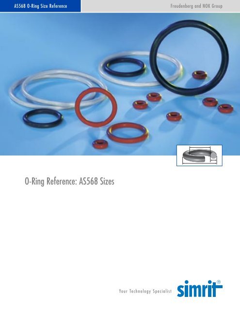
O-<strong>Ring</strong> <strong>Reference</strong>: <strong>AS568</strong> <strong>Sizes</strong><br />
Your Technology Specialist
The <strong>Simrit</strong> O-<strong>Ring</strong> Design Quick <strong>Reference</strong><br />
This design quick reference guide is intended for use<br />
in specifying O-ring and groove dimensions for static<br />
applications with pressures less than 1500 psi.<br />
The guidelines are for the nominal condition. The minimum<br />
and maximum conditions should also be checked. This<br />
requires looking at the dimensionally largest possible<br />
O-ring in the smallest possible groove (i.e., at the hardware<br />
and O-ring tolerance stack-up) and the smallest<br />
possible O-ring in the largest possible groove.<br />
O-<strong>Ring</strong> Gland Types and Nomenclature<br />
Most static O-ring seals can be classified into one of the<br />
three arrangements shown below. The variable names<br />
Piston-Type Seal<br />
Piston<br />
Gland<br />
Bore<br />
Face-Type Seal<br />
Out<br />
In<br />
H<br />
W<br />
W<br />
H<br />
Throughout this reference guide the term “compression”<br />
is used for describing what provides the sealing force.<br />
Since elastomers are essentially incompressible, the<br />
technically correct term would be “deformation.”<br />
Compression is used, as it is the more commonly used<br />
terminology in the industry.<br />
presented in these diagrams are used throughout the<br />
quick reference guide.<br />
Rod-Type Seal<br />
Rod<br />
Gland<br />
Bore<br />
H<br />
W<br />
1
2<br />
Gland Dimension Calculations<br />
Although each physical arrangement is different, typically<br />
the O-ring is captured in a rectangular gland. Two<br />
opposing surfaces are sealing surfaces, in that the<br />
distance between them, the gland height (H), is less than<br />
the O-ring cross-section (CS) so that the installed O-ring<br />
is compressed, resulting in a sealing force. The other two<br />
O-<strong>Ring</strong> Dimensions Gland Dimensions<br />
ID<br />
OD<br />
Piston-Type Seal<br />
Bore – Gland<br />
H = W = W<br />
2<br />
ID Stretch/OD Interference<br />
CS<br />
Rod-Type Seal<br />
The ID or OD of the O-ring should be chosen to minimize<br />
the potential for installation damage and to minimize wear<br />
during use.<br />
For piston-type seals the ID of the O-ring should be<br />
smaller than the gland diameter so that the installed<br />
O-ring is always slightly stretched, even with the<br />
largest possible O-ring ID and smallest possible<br />
gland diameter.<br />
For rod-type seals the OD of the O-ring should be<br />
slightly larger than the gland diameter so that there is<br />
always some interference.<br />
Piston-Type Seal<br />
Stretch =<br />
Rod-Type Seal<br />
Interference =<br />
Gland – ID<br />
ID<br />
OD – Gland<br />
OD<br />
Maximum = 5%<br />
Minimum = 0%<br />
Maximum = 2%<br />
Minimum = 0%<br />
Gland Width (W)<br />
Gland<br />
Height<br />
(H)<br />
Gland – Rod<br />
H = W = W<br />
2<br />
opposing surfaces are containing surfaces in that the<br />
distance between them, the gland width (W), is larger<br />
than the O-ring cross-section so that they serve to keep the<br />
O-ring in place. Calculations of basic gland dimensions<br />
for piston type, rod type and face seals are shown below.<br />
Containing Surface<br />
Sealing Surface<br />
Sealing Surface<br />
Face-Type Seal<br />
Containing Surface<br />
Out – In<br />
H = H W =<br />
2<br />
For external pressure face seals, the ID of the O-ring<br />
should be slightly smaller than the inner diameter (In)<br />
so that when the pressure is applied, the O-ring is<br />
already where it would be as a result of the pressure.<br />
For internal pressure face seals, the OD of the O-ring<br />
should be slightly larger than the outer diameter (Out)<br />
so that when the pressure is applied, the O-ring is<br />
already where it would be as a result of the pressure.<br />
External Pressure Face-Type Seal<br />
Stretch =<br />
In – ID<br />
ID<br />
Internal Pressure Face-Type Seal<br />
Interference =<br />
OD – Out<br />
OD<br />
Maximum = 5%<br />
Minimum = 0%<br />
Maximum = 3%<br />
Minimum = 0%
Reduction in Cross-Section<br />
Since elastomers are essentially incompressible materials,<br />
if the ID of the O-ring is stretched, the cross-section of<br />
the O-ring will decrease. The following tables give the<br />
O-ring cross-sections that result from ID stretch. The new<br />
cross-section should be used for all compression and<br />
<strong>AS568</strong> Original Cross-Section Reduced Cross-Section at<br />
Series in Inches % ID Stretch (inches)<br />
1% 2% 3% 4% 5%<br />
- 0XX 0.070 in. .069 .069 .068 .068 .068<br />
-1XX 0.103 in. .102 .101 .100 .100 .100<br />
-2XX 0.139 in. .138 .137 .136 .135 .134<br />
-3XX 0.210 in. .208 .206 .205 .204 .203<br />
-4XX 0.275 in. .272 .270 .268 .267 .266<br />
<strong>AS568</strong> Original Cross-Section Reduced Cross-Section at<br />
Series in Millimeters % ID Stretch (millimeters)<br />
1% 2% 3% 4% 5%<br />
-0XX 1.78 mm 1.76 1.75 1.74 1.73 1.72<br />
-1XX 2.62 mm 2.59 2.57 2.56 2.55 2.53<br />
-2XX 3.53 mm 3.49 3.47 3.44 3.43 3.41<br />
-3XX 5.33 mm 5.28 5.24 5.20 5.18 5.15<br />
-4XX 6.99 mm 6.92 6.87 6.82 6.79 6.75<br />
Compression Squeeze<br />
Compression squeeze is the difference between the original<br />
O-ring cross-section (CS) and the gland height (H). It is<br />
expressed in either inches or mm.<br />
Compression Squeeze<br />
CS H<br />
Compression Squeeze<br />
gland fill calculations for piston-type and external<br />
pressure face seals.<br />
The impact of OD interference on the O-ring cross-section<br />
varies and does not typically require design considerations.<br />
Calculation<br />
Compression Squeeze = CS – H<br />
Recommended Minimum Value<br />
Compression Squeeze > 0.005 inch (0.1 mm)<br />
3
4<br />
Compression Ratio<br />
The compression ratio is the ratio between compression<br />
squeeze and the uncompressed O-ring cross-section.<br />
Calculation<br />
Compression Squeeze<br />
Compression Ratio (%) = x 100<br />
CS<br />
Gland Fill<br />
Gland fill is the percentage of the gland that is<br />
occupied by the O-ring. It is calculated by dividing<br />
The following target gland fill recommendations take into<br />
account several hardware and O-ring-related factors<br />
including but not limited to thermal expansion, volume<br />
swell due to fluid exposure, and the effect of tolerance<br />
Recommended Value<br />
Piston- or Rod-Type Seal<br />
Minimum: 5% Target: 20% Maximum: 30%<br />
Face-Type Seal<br />
Minimum: 10% Target: 25% Maximum: 35%<br />
O-<strong>Ring</strong> Cross-Section Area Gland Cross-Section Area Gland Fill<br />
CS 2<br />
O-<strong>Ring</strong> CSA = π x( 2 )<br />
O-<strong>Ring</strong><br />
CSA<br />
CS<br />
Recommended Values<br />
Gland CSA = H x W*<br />
H<br />
Gland<br />
CSA<br />
Target Minimum: 65% Target: 75% Target Maximum: 85%<br />
W<br />
* Effect of gland angle not addressed<br />
Compression ratio is typically expressed as a percentage.<br />
the cross-sectional area (CSA) of the O-ring by the<br />
cross-sectional area of the gland.<br />
O-<strong>Ring</strong> CSA<br />
Gland Fill (%) = x 100<br />
Gland CSA<br />
stack-ups. A gland fill as low as 50% and as high as<br />
90% is acceptable, but it is recommended that the<br />
targets shown below be adhered to whenever possible.
Extrusion Gap<br />
Extrusion is a concern for radial seals where there is a<br />
gap between the piston and the bore for a piston-type<br />
seal or between the rod and the bore for a rod-type<br />
seal. It is not typically a concern for face seals where the<br />
metal parts to be sealed are in contact line-to-line. The<br />
issue is that at higher pressures and especially for softer<br />
Piston-Type Seal<br />
Extrusion Gap = Bore – Piston<br />
Extrusion<br />
Gap<br />
Extrusion<br />
Maximum Recommended Extrusion Gap in Inches (mm)<br />
Pressure Elastomer Hardness<br />
(PSI) (Durometer)<br />
60 70 80 90<br />
Rod-Type Seal<br />
500 .010 (.25) .015 (.38) .020 (.51) .025 (.64)<br />
750 .005 (.13) .011 (.28) .016 (.41) .023 (.58)<br />
1000 .002 (.05) .008 (.20) .012 (.30) .018 (.46)<br />
1250 .001 (.02) .004 (.10) .009 (.23) .015 (.38)<br />
1500 Consult <strong>Simrit</strong> .002 (.05) .007 (.18) .012 (.30)<br />
For pressures greater than 1500 psi consult <strong>Simrit</strong>.<br />
High<br />
Pressure<br />
O-ring elastomers, the O-ring can be forced by the<br />
pressure into the small gap between the piston or rod<br />
and the bore. Unless the hardware can ensure the bore<br />
and the piston or rod remain concentric, we have to<br />
assume that all of the gap possible can shift to one<br />
side (see diagram below).<br />
Extrusion Gap = Bore – Rod<br />
Concentricity and Diametric Clearance<br />
Maximum Possible Extrusion Gap<br />
5
6<br />
Other Groove Details<br />
In addition to proper compression and gland fill, a<br />
properly designed and machined gland is essential for a<br />
good O-ring seal. The tables at the right and the diagram<br />
below provide the recommended gland design parameters.<br />
In addition, the gland surfaces must be free from all<br />
machining irregularities, and the gland edges should be<br />
smooth and true and free of nicks, scratches, and burrs.<br />
Installation Aids<br />
Groove Detail Diagram<br />
Wall<br />
Angle<br />
Containing Surface<br />
Sealing Surface<br />
Break Edge<br />
Radius<br />
Sealing<br />
Surface<br />
A perfectly designed O-ring seal is of little use if the<br />
O-ring is damaged during installation. To prevent<br />
installation damage for piston-type and rod-type seals,<br />
we recommend a 15° chamfer on the bore or rod. The<br />
Installation Chamfer Length<br />
Detail Inch mm<br />
Wall Angle 0° to 5° 0° to 5°<br />
Break Edge .005 to .010 .13 to .25<br />
Static Sealing 32 µinch 0.8 µm<br />
Surface Finish maximum maximum<br />
Static Contain 64 µinch 1.6 µm<br />
Surface Finish maximum maximum<br />
Radius See table below<br />
<strong>AS568</strong> Radius Radius<br />
Series (inch) (mm)<br />
Min. Max. Min. Max.<br />
-0XX .005 .015 .13 .38<br />
-1XX .005 .015 .13 .38<br />
-2XX .010 .025 .25 .64<br />
-3XX .020 .035 .51 .89<br />
-4XX .020 .035 .51 .89<br />
chamfer must be long enough to ensure that the O-ring<br />
sees only the chamfer when it is installed. Face-type<br />
seals do not require design considerations beyond the<br />
groove detail recommendations offered above.<br />
<strong>AS568</strong> O-<strong>Ring</strong> CS Chamfer Length<br />
Series Inches mm Inches mm<br />
-0XX .070 1.78 .083 2.10<br />
-1XX .103 2.62 .122 3.10<br />
-2XX .139 3.53 .157 4.00<br />
-3XX .210 5.33 .236 6.00<br />
-4XX .275 6.99 .283 7.20
Properties of Commonly Used Elastomers<br />
Material Name Simriz ® Super Aflas Fluoro- Ethylene Nitrile Silicone Fluoro-<br />
FKM carbon Propylene silicone<br />
ASTM D1418 Designation FFKM ETP TFE/P FKM EPDM NBR VMQ FVMQ<br />
Typical Colors<br />
OPERATING TEMPERATURE RANGE<br />
Black Black Black Black Black Black Red Blue<br />
White White White Purple White<br />
Clear Brown<br />
Green<br />
Low Temperature –20°C –20°C –10°C –40°C –55°C –50°C –75°C –65°C<br />
–4°F –4°F +14°F –40°F –67°F –58°F –103°F –85°F<br />
High Temperature 300°C 200°C 200°C 250°C 150°C 120°C 230°C 180°C<br />
572°F 392°F 392°F 482°F 302°F 248°F 446°F 356°F<br />
PHYSICAL PROPERTIES<br />
Abrasion Resistance 3 2 2 2 1 2 4 4<br />
Permeation Resistance 2 2 2 1 2 2 4 4<br />
Compression Set Resistance 2 2 2 1 2 1 1 1<br />
Tear Resistance 3 3 3 3 1 2 4 4<br />
CHEMICAL COMPATIBILITY<br />
Inorganic<br />
Acids 1 1 1 1 1 2 3 2<br />
Bases 1 2 1 4 1 2 3 3<br />
Organic<br />
Acids 1 1 1 1 1 2 3 2<br />
Alcohols 1 1 1 3 1 1 1 1<br />
Aldehydes 1 2 4 3 1 3 2 4<br />
Amines 2 2 1 4 1 4 2 4<br />
Aromatic Hydrocarbons 1 1 4 1 4 3 4 1<br />
Ether 1 3 4 4 3 4 4 3<br />
Halogenides 2 1 4 1 4 4 4 4<br />
Ketone 1 3 4 4 1 4 4 4<br />
Water 1 1 1 1 1 1 1 1<br />
Steam (149°C/300°F) 2 3 3 4 4 4 4 4<br />
Material Rating: 1—Little or no effect (volume change 40%) 0—Insufficient information<br />
7
8<br />
Elastomer Materials<br />
Simriz® Perfluoroelastomer<br />
Designation: FFKM<br />
Description: Excellent resistance to all chemicals.<br />
Excellent outgassing performance in vacuum environments.<br />
Limitations: Avoid low-molecular-weight, fully halogenated<br />
fluids and molten alkali metals. Strong oxidizing acids<br />
may cause some swelling. Poor compression set may not<br />
be suitable for some applications. Helium permeability is<br />
slightly higher than fluoroelastomer compounds. Specific<br />
Simriz compounds provide better low-temperature<br />
performance and amine resistance.<br />
Temperature Range: –20° to 300°C (–4° to 572°F)<br />
Highly Fluorinated Fluoroelastomers<br />
Designation: ETP (Viton®)<br />
Description: Excellent resistance to most chemicals. The<br />
performance of these products is greater than traditional<br />
fluoroelastomers.<br />
Limitations: Contamination performance is somewhat<br />
less than Simriz perfluoroelastomer. Avoid service in<br />
strong bases or amines.<br />
Temperature Range: –20° to 200°C (–4° to 392°F)<br />
Tetrafluoroethylene/Propylene Elastomers<br />
Designation: TFE/P (Aflas®)<br />
Description: Fluorocarbon elastomer noted for exceptional<br />
thermal and chemical resistance. Excellent resistance to<br />
acids, bases, water, and amines. Widely used in oil fields.<br />
Limitations: Avoid polar solvents and aromatic fuels.<br />
Compression set performance may be too high for some<br />
applications.<br />
Temperature Range: –10° to 200°C (14° to 400°F)<br />
Viton ® is a registered trademarks of DuPont.<br />
Aflas ® is a registered trademark of Asahi Glass Co.<br />
Standard Fluoroelastomers<br />
Designation: FKM<br />
Description: Excellent resistance to petroleum products<br />
and solvents. Very good high-temperature performance.<br />
Fluorocarbon elastomers make up the most widely used<br />
seals in the semiconductor industry.<br />
Limitations: Avoid polar solvents, amines, anhydrous<br />
ammonia, SKYDROL, hydrazine, and hot acids.<br />
Temperature Range: –40° to 200°C (–40° to 392°F)<br />
Hydrocarbon Elastomers—Ethylene-Propylene<br />
Designation: EP, EPDM<br />
Description: Excellent resistance to water, steam, and<br />
polar solvents, as well as ozone and sunlight. Also<br />
resistant to alcohols, glycol engine coolants, and<br />
SKYDROL (phosphate ester hydraulic fluid). Divided into<br />
sulphur-cured and peroxide-cured types. Peroxide-cured<br />
compounds are suitable for higher temperatures and<br />
have much lower compression sets.<br />
Limitations: Avoid non-polar solvents, petroleum oils,<br />
and aromatic fuels.<br />
Temperature Range: –55° to 150°C (–67° to 302°F)<br />
Hydrocarbon Elastomers—Nitrile<br />
Designation: NBR, XNBR, HNBR<br />
Description: Very commonly used for O-rings because of<br />
its good mechanical properties and low cost. Standard<br />
Nitrile is also known as Buna-N. Excellent resistance to<br />
petroleum-based oils and fuels, water and alcohols.<br />
Nitrile also has good resistance to acids and bases,<br />
except those with a strong oxidizing effect. HNBR is<br />
obtained by partially or fully hydrogenating NBR leading<br />
to considerable improvement of the resistance to heat,<br />
ozone, and aging.<br />
Limitations: Avoid highly polar solvents (Acetone, MEK,<br />
etc.) and direct exposure to ozone and sunlight.<br />
Temperature Range: –55° to 120°C (–65° to 248°F)
Elastomer Materials—continued<br />
Silicone Elastomers—Silicone<br />
Designation: MQ, PMQ, VMQ, PVMQ<br />
Description: Excellent material for static service at extreme<br />
(hot or cold) temperatures. Outstanding flex and fatigue<br />
life. Very good for ozone and UV radiation service as<br />
well as for resistance to fungal and biological attack.<br />
Limitations: Avoid chlorinated solvents, aliphatic and<br />
aromatic hydrocarbons and petroleum oils. Silicones<br />
are generally very permeable to gases and have poor<br />
physical strength and abrasion resistance.<br />
Temperature Range: –115° to 232°C (–175° to 450°F)<br />
Fluorosilicone Elastomers—Fluorosilicone<br />
Designation: FVMQ<br />
Description: Combines excellent low-temperature performance<br />
of silicone with improved chemical resistance.<br />
Very good resistance to military and aerospace fuels.<br />
Excellent performance in oxygen plasma environments.<br />
Limitations: Avoid polar solvents, hydrocarbon fluids<br />
and phosphate ester brake fluids. Susceptible to hydrolysis<br />
by acids and bases. Limited abrasion resistance.<br />
Temperature Range: –60° to 180°C (–76° to 356°F)<br />
Comparative Temperature/Chemical Resistance Limits<br />
HIGH-TEMPERATURE RESISTANCE<br />
Nitrile (NBR)<br />
Silicone (VMQ)<br />
Perfluoroether<br />
Designation: FFO<br />
Fluorocarbon (FKM)<br />
Hydrogenated Nitrile (HNBR)<br />
CHEMICAL RESISTANCE<br />
Description: Combines low-temperature flexibility, fuel<br />
resistance, oil resistance, high-temperature stability, and<br />
phosphate ester fluid resistance. Excellent performance<br />
in jet fuel, piston and jet engine lubricants, and all types<br />
of aircraft hydraulic systems.<br />
Limitations: Avoid ketone solvents.<br />
Temperature Range: –65° to 200°C (–85°F to 392°F)<br />
Aflas ® (TFE/P)<br />
SIMRIZ ® (FFKM)<br />
Fluorosilicone (FVMQ)<br />
9
10<br />
Six Sigma Quality<br />
<strong>Simrit</strong> O-rings often exceed Six Sigma levels of quality.<br />
By optimizing material and manufacturing processes,<br />
<strong>Simrit</strong> ensures the highest quality output with virtually no<br />
manufacturing imperfections. Automated vision systems<br />
are often used to double-check characteristics which are<br />
imperceptible to the human eye, with the goal of producing<br />
better than Six Sigma Quality.<br />
What is Six Sigma?<br />
Motorola pioneered the notion of Six Sigma Quality as<br />
a way to improve processes and decrease defect levels.<br />
A process capability index (Cp) is used to measure the<br />
relationship between the measured values of a statistical<br />
sample and the specified tolerance range. A process<br />
with a Cp of 1.00 will use the entire allowable tolerance.<br />
This is known as Three Sigma Quality. Six Sigma Quality<br />
stresses refining of the process to achieve a Cp of 2.00.<br />
As an example of industry standards, the Aerospace<br />
O-ring industry is currently operating at about 1.33 Cp<br />
for dimensional conformance, with the next target being<br />
a 1.67 Cp.<br />
Practical Impact of Long-Term Process Capability<br />
Sigma Defects per Cost of Poor Quality<br />
Million Parts<br />
SIX 3.4 Defects
<strong>AS568</strong> Dimensions<br />
<strong>AS568</strong> is the Aerospace Size Standard for O-rings from the Society of Automotive Engineers.<br />
<strong>Simrit</strong> manufactures and supplies the complete range of standard <strong>AS568</strong> sizes in a wide<br />
range of elastomeric O-ring materials. The following sizes are grouped by cross-section and<br />
listed numerically by inside diameter.<br />
<strong>AS568</strong> Nominal (refer.) Measurements in inches Measurements in millimeters <strong>AS568</strong><br />
SIZE ID CS ID ± CS ± ID ± CS ± SIZE<br />
-001 1/32 1/32 0.029 0.004 0.040 0.003 0.74 0.10 1.02 0.08 -001<br />
-002 3/64 3/64 0.042 0.004 0.050 0.003 1.07 0.10 1.27 0.08 -002<br />
-003 1/16 1/16 0.056 0.004 0.060 0.003 1.42 0.10 1.52 0.08 -003<br />
-004 5/64 1/16 0.070 0.005 0.070 0.003 1.78 0.13 1.78 0.08 -004<br />
-005 3/32 1/16 0.101 0.005 0.070 0.003 2.57 0.13 1.78 0.08 -005<br />
-006 1/8 1/16 0.114 0.005 0.070 0.003 2.90 0.13 1.78 0.08 -006<br />
-007 5/32 1/16 0.145 0.005 0.070 0.003 3.68 0.13 1.78 0.08 -007<br />
-008 3/16 1/16 0.176 0.005 0.070 0.003 4.47 0.13 1.78 0.08 -008<br />
-009 7/32 1/16 0.208 0.005 0.070 0.003 5.28 0.13 1.78 0.08 -009<br />
-010 1/4 1/16 0.239 0.005 0.070 0.003 6.07 0.13 1.78 0.08 -010<br />
-011 5/16 1/16 0.301 0.005 0.070 0.003 7.65 0.13 1.78 0.08 -011<br />
-012 3/8 1/16 0.364 0.005 0.070 0.003 9.25 0.13 1.78 0.08 -012<br />
-013 7/16 1/16 0.426 0.005 0.070 0.003 10.82 0.13 1.78 0.08 -013<br />
-014 1/2 1/16 0.489 0.005 0.070 0.003 12.42 0.13 1.78 0.08 -014<br />
-015 9/16 1/16 0.551 0.007 0.070 0.003 14.00 0.18 1.78 0.08 -015<br />
-016 5/8 1/16 0.614 0.009 0.070 0.003 15.60 0.23 1.78 0.08 -016<br />
-017 11/16 1/16 0.676 0.009 0.070 0.003 17.17 0.23 1.78 0.08 -017<br />
-018 3/4 1/16 0.739 0.009 0.070 0.003 18.77 0.23 1.78 0.08 -018<br />
-019 13/16 1/16 0.801 0.009 0.070 0.003 20.35 0.23 1.78 0.08 -019<br />
-020 7/8 1/16 0.864 0.009 0.070 0.003 21.95 0.23 1.78 0.08 -020<br />
-021 15/16 1/16 0.926 0.009 0.070 0.003 23.52 0.23 1.78 0.08 -021<br />
-022 1 1/16 0.989 0.010 0.070 0.003 25.12 0.25 1.78 0.08 -022<br />
-023 1 1/16 1/16 1.051 0.010 0.070 0.003 26.70 0.25 1.78 0.08 -023<br />
-024 1 1/8 1/16 1.114 0.010 0.070 0.003 28.30 0.25 1.78 0.08 -024<br />
-025 1 3/16 1/16 1.176 0.011 0.070 0.003 29.87 0.28 1.78 0.08 -025<br />
-026 1 1/4 1/16 1.239 0.011 0.070 0.003 31.47 0.28 1.78 0.08 -026<br />
-027 1 5/16 1/16 1.301 0.011 0.070 0.003 33.05 0.28 1.78 0.08 -027<br />
-028 1 3/8 1/16 1.364 0.013 0.070 0.003 34.65 0.33 1.78 0.08 -028<br />
-029 1 1/2 1/16 1.489 0.013 0.070 0.003 37.82 0.33 1.78 0.08 -029<br />
-030 1 5/8 1/16 1.614 0.013 0.070 0.003 41.00 0.33 1.78 0.08 -030<br />
-031 1 3/4 1/16 1.739 0.015 0.070 0.003 44.17 0.38 1.78 0.08 -031<br />
-032 1 7/8 1/16 1.864 0.015 0.070 0.003 47.35 0.38 1.78 0.08 -032<br />
-033 2 1/16 1.989 0.018 0.070 0.003 50.52 0.46 1.78 0.08 -033<br />
-034 2 1/8 1/16 2.114 0.018 0.070 0.003 53.70 0.46 1.78 0.08 -034<br />
-035 2 1/4 1/16 2.239 0.018 0.070 0.003 56.87 0.46 1.78 0.08 -035<br />
-036 2 3/8 1/16 2.364 0.018 0.070 0.003 60.05 0.46 1.78 0.08 -036<br />
-037 2 1/2 1/16 2.489 0.018 0.070 0.003 63.22 0.46 1.78 0.08 -037<br />
-038 2 5/8 1/16 2.614 0.020 0.070 0.003 66.40 0.51 1.78 0.08 -038<br />
-039 2 3/4 1/16 2.739 0.020 0.070 0.003 69.57 0.51 1.78 0.08 -039<br />
-040 2 7/8 1/16 2.864 0.020 0.070 0.003 72.75 0.51 1.78 0.08 -040<br />
-041 3 1/16 2.989 0.024 0.070 0.003 75.92 0.61 1.78 0.08 -041<br />
-042 3 1/4 1/16 3.239 0.024 0.070 0.003 82.27 0.61 1.78 0.08 -042<br />
-043 3 1/2 1/16 3.489 0.024 0.070 0.003 88.62 0.61 1.78 0.08 -043<br />
-044 3 3/4 1/16 3.739 0.027 0.070 0.003 94.97 0.69 1.78 0.08 -044<br />
-045 4 1/16 3.989 0.027 0.070 0.003 101.32 0.69 1.78 0.08 -045<br />
-046 4 1/4 1/16 4.239 0.030 0.070 0.003 107.67 0.76 1.78 0.08 -046<br />
-047 4 1/2 1/16 4.489 0.030 0.070 0.003 114.02 0.76 1.78 0.08 -047<br />
-048 4 3/4 1/16 4.739 0.030 0.070 0.003 120.37 0.76 1.78 0.08 -048<br />
-049 5 1/16 4.989 0.037 0.070 0.003 126.72 0.94 1.78 0.08 -049<br />
-050 5 1/4 1/16 5.239 0.037 0.070 0.003 133.07 0.94 1.78 0.08 -050<br />
11<br />
OD<br />
CS<br />
ID
<strong>AS568</strong> Dimensions<br />
<strong>AS568</strong> is the Aerospace Size Standard for O-rings from the Society of Automotive Engineers.<br />
<strong>Simrit</strong> manufactures and supplies the complete range of standard <strong>AS568</strong> sizes in a wide<br />
range of elastomeric O-ring materials. The following sizes are grouped by cross-section and<br />
listed numerically by inside diameter.<br />
<strong>AS568</strong> Nominal (refer.) Measurements in inches Measurements in millimeters <strong>AS568</strong><br />
SIZE ID CS ID ± CS ± ID ± CS ± SIZE<br />
-102 1/16 3/32 0.049 0.005 0.103 0.003 1.24 0.13 2.62 0.08 -102<br />
-103 3/32 3/32 0.081 0.005 0.103 0.003 2.06 0.13 2.62 0.08 -103<br />
-104 1/8 3/32 0.112 0.005 0.103 0.003 2.84 0.13 2.62 0.08 -104<br />
-105 5/32 3/32 0.143 0.005 0.103 0.003 3.63 0.13 2.62 0.08 -105<br />
-106 3/16 3/32 0.174 0.005 0.103 0.003 4.42 0.13 2.62 0.08 -106<br />
-107 7/32 3/32 0.206 0.005 0.103 0.003 5.23 0.13 2.62 0.08 -107<br />
-108 1/4 3/32 0.237 0.005 0.103 0.003 6.02 0.13 2.62 0.08 -108<br />
-109 5/16 3/32 0.299 0.005 0.103 0.003 7.59 0.13 2.62 0.08 -109<br />
-110 3/8 3/32 0.362 0.005 0.103 0.003 9.19 0.13 2.62 0.08 -110<br />
-111 7/16 3/32 0.424 0.005 0.103 0.003 10.77 0.13 2.62 0.08 -111<br />
-112 1/2 3/32 0.487 0.005 0.103 0.003 12.37 0.13 2.62 0.08 -112<br />
-113 9/16 3/32 0.549 0.007 0.103 0.003 13.94 0.18 2.62 0.08 -113<br />
-114 5/8 3/32 0.612 0.009 0.103 0.003 15.54 0.23 2.62 0.08 -114<br />
-115 11/16 3/32 0.674 0.009 0.103 0.003 17.12 0.23 2.62 0.08 -115<br />
-116 3/4 3/32 0.737 0.009 0.103 0.003 18.72 0.23 2.62 0.08 -116<br />
-117 13/16 3/32 0.799 0.010 0.103 0.003 20.29 0.25 2.62 0.08 -117<br />
-118 7/8 3/32 0.862 0.010 0.103 0.003 21.89 0.25 2.62 0.08 -118<br />
-119 15/16 3/32 0.924 0.010 0.103 0.003 23.47 0.25 2.62 0.08 -119<br />
-120 1 3/32 0.987 0.010 0.103 0.003 25.07 0.25 2.62 0.08 -120<br />
-121 1 1/16 3/32 1.049 0.010 0.103 0.003 26.64 0.25 2.62 0.08 -121<br />
-122 1 1/8 3/32 1.112 0.010 0.103 0.003 28.24 0.25 2.62 0.08 -122<br />
-123 1 3/16 3/32 1.174 0.012 0.103 0.003 29.82 0.30 2.62 0.08 -123<br />
-124 1 1/4 3/32 1.237 0.012 0.103 0.003 31.42 0.30 2.62 0.08 -124<br />
-125 1 5/16 3/32 1.299 0.012 0.103 0.003 32.99 0.30 2.62 0.08 -125<br />
-126 1 3/8 3/32 1.362 0.012 0.103 0.003 34.59 0.30 2.62 0.08 -126<br />
-127 1 7/16 3/32 1.424 0.012 0.103 0.003 36.17 0.30 2.62 0.08 -127<br />
-128 1 1/2 3/32 1.487 0.012 0.103 0.003 37.77 0.30 2.62 0.08 -128<br />
-129 1 9/16 3/32 1.549 0.015 0.103 0.003 39.34 0.38 2.62 0.08 -129<br />
-130 1 5/8 3/32 1.612 0.015 0.103 0.003 40.94 0.38 2.62 0.08 -130<br />
-131 1 11/16 3/32 1.674 0.015 0.103 0.003 42.52 0.38 2.62 0.08 -131<br />
-132 1 3/4 3/32 1.737 0.015 0.103 0.003 44.12 0.38 2.62 0.08 -132<br />
-133 1 13/16 3/32 1.799 0.015 0.103 0.003 45.69 0.38 2.62 0.08 -133<br />
-134 1 7/8 3/32 1.862 0.015 0.103 0.003 47.29 0.38 2.62 0.08 -134<br />
-135 1 15/16 3/32 1.925 0.017 0.103 0.003 48.90 0.43 2.62 0.08 -135<br />
-136 2 3/32 1.987 0.017 0.103 0.003 50.47 0.43 2.62 0.08 -136<br />
-137 2 1/16 3/32 2.050 0.017 0.103 0.003 52.07 0.43 2.62 0.08 -137<br />
-138 2 1/8 3/32 2.112 0.017 0.103 0.003 53.64 0.43 2.62 0.08 -138<br />
-139 2 3/16 3/32 2.175 0.017 0.103 0.003 55.25 0.43 2.62 0.08 -139<br />
-140 2 1/4 3/32 2.237 0.017 0.103 0.003 56.82 0.43 2.62 0.08 -140<br />
-141 2 5/16 3/32 2.300 0.020 0.103 0.003 58.42 0.51 2.62 0.08 -141<br />
-142 2 3/8 3/32 2.362 0.020 0.103 0.003 59.99 0.51 2.62 0.08 -142<br />
-143 2 7/16 3/32 2.425 0.020 0.103 0.003 61.60 0.51 2.62 0.08 -143<br />
-144 2 1/2 3/32 2.487 0.020 0.103 0.003 63.17 0.51 2.62 0.08 -144<br />
-145 2 9/16 3/32 2.550 0.020 0.103 0.003 64.77 0.51 2.62 0.08 -145<br />
-146 2 5/8 3/32 2.612 0.020 0.103 0.003 66.34 0.51 2.62 0.08 -146<br />
-147 2 11/16 3/32 2.675 0.022 0.103 0.003 67.95 0.56 2.62 0.08 -147<br />
-148 2 3/4 3/32 2.737 0.022 0.103 0.003 69.52 0.56 2.62 0.08 -148<br />
-149 2 13/16 3/32 2.800 0.022 0.103 0.003 71.12 0.56 2.62 0.08 -149<br />
-150 2 7/8 3/32 2.862 0.022 0.103 0.003 72.69 0.56 2.62 0.08 -150<br />
12<br />
OD<br />
CS<br />
ID
<strong>AS568</strong> Dimensions<br />
<strong>AS568</strong> is the Aerospace Size Standard for O-rings from the Society of Automotive Engineers.<br />
<strong>Simrit</strong> manufactures and supplies the complete range of standard <strong>AS568</strong> sizes in a wide<br />
range of elastomeric O-ring materials. The following sizes are grouped by cross-section and<br />
listed numerically by inside diameter.<br />
<strong>AS568</strong> Nominal (refer.) Measurements in inches Measurements in millimeters <strong>AS568</strong><br />
SIZE ID CS ID ± CS ± ID ± CS ± SIZE<br />
-151 3 3/32 2.987 0.024 0.103 0.003 75.87 0.61 2.62 0.08 -151<br />
-152 3 1/4 3/32 3.237 0.024 0.103 0.003 82.22 0.61 2.62 0.08 -152<br />
-153 3 1/2 3/32 3.487 0.024 0.103 0.003 88.57 0.61 2.62 0.08 -153<br />
-154 3 3/4 3/32 3.737 0.028 0.103 0.003 94.92 0.71 2.62 0.08 -154<br />
-155 4 3/32 3.987 0.028 0.103 0.003 101.27 0.71 2.62 0.08 -155<br />
-156 4 1/4 3/32 4.237 0.030 0.103 0.003 107.62 0.76 2.62 0.08 -156<br />
-157 4 1/2 3/32 4.487 0.030 0.103 0.003 113.97 0.76 2.62 0.08 -157<br />
-158 4 3/4 3/32 4.737 0.030 0.103 0.003 120.32 0.76 2.62 0.08 -158<br />
-159 5 3/32 4.987 0.035 0.103 0.003 126.67 0.89 2.62 0.08 -159<br />
-160 5 1/4 3/32 5.237 0.035 0.103 0.003 133.02 0.89 2.62 0.08 -160<br />
-161 5 1/2 3/32 5.487 0.035 0.103 0.003 139.37 0.89 2.62 0.08 -161<br />
-162 5 3/4 3/32 5.737 0.035 0.103 0.003 145.72 0.89 2.62 0.08 -162<br />
-163 6 3/32 5.987 0.035 0.103 0.003 152.07 0.89 2.62 0.08 -163<br />
-164 6 1/4 3/32 6.237 0.040 0.103 0.003 158.42 1.02 2.62 0.08 -164<br />
-165 6 1/2 3/32 6.487 0.040 0.103 0.003 164.77 1.02 2.62 0.08 -165<br />
-166 6 3/4 3/32 6.737 0.040 0.103 0.003 171.12 1.02 2.62 0.08 -166<br />
-167 7 3/32 6.987 0.040 0.103 0.003 177.47 1.02 2.62 0.08 -167<br />
-168 7 1/4 3/32 7.237 0.045 0.103 0.003 183.82 1.14 2.62 0.08 -168<br />
-169 7 1/2 3/32 7.487 0.045 0.103 0.003 190.17 1.14 2.62 0.08 -169<br />
-170 7 3/4 3/32 7.737 0.045 0.103 0.003 196.52 1.14 2.62 0.08 -170<br />
-171 8 3/32 7.987 0.045 0.103 0.003 202.87 1.14 2.62 0.08 -171<br />
-172 8 1/4 3/32 8.237 0.050 0.103 0.003 209.22 1.27 2.62 0.08 -172<br />
-173 8 1/2 3/32 8.487 0.050 0.103 0.003 215.57 1.27 2.62 0.08 -173<br />
-174 8 3/4 3/32 8.737 0.050 0.103 0.003 221.92 1.27 2.62 0.08 -174<br />
-175 9 3/32 8.987 0.050 0.103 0.003 228.27 1.27 2.62 0.08 -175<br />
-176 9 1/4 3/32 9.237 0.055 0.103 0.003 234.62 1.40 2.62 0.08 -176<br />
-177 9 1/2 3/32 9.487 0.055 0.103 0.003 240.97 1.40 2.62 0.08 -177<br />
-178 9 3/4 3/32 9.737 0.055 0.103 0.003 247.32 1.40 2.62 0.08 -178<br />
13<br />
OD<br />
CS<br />
ID
<strong>AS568</strong> Dimensions<br />
<strong>AS568</strong> is the Aerospace Size Standard for O-rings from the Society of Automotive Engineers.<br />
<strong>Simrit</strong> manufactures and supplies the complete range of standard <strong>AS568</strong> sizes in a wide<br />
range of elastomeric O-ring materials. The following sizes are grouped by cross-section and<br />
listed numerically by inside diameter.<br />
<strong>AS568</strong> Nominal (refer.) Measurements in inches Measurements in millimeters <strong>AS568</strong><br />
SIZE ID CS ID ± CS ± ID ± CS ± SIZE<br />
-201 3/16 1/8 0.171 0.005 0.139 0.004 4.34 0.13 3.53 0.10 -201<br />
-202 1/4 1/8 0.234 0.005 0.139 0.004 5.94 0.13 3.53 0.10 -202<br />
-203 5/16 1/8 0.296 0.005 0.139 0.004 7.52 0.13 3.53 0.10 -203<br />
-204 3/8 1/8 0.359 0.005 0.139 0.004 9.12 0.13 3.53 0.10 -204<br />
-205 7/16 1/8 0.421 0.005 0.139 0.004 10.69 0.13 3.53 0.10 -205<br />
-206 1/2 1/8 0.484 0.005 0.139 0.004 12.29 0.13 3.53 0.10 -206<br />
-207 9/16 1/8 0.546 0.007 0.139 0.004 13.87 0.18 3.53 0.10 -207<br />
-208 5/8 1/8 0.609 0.009 0.139 0.004 15.47 0.23 3.53 0.10 -208<br />
-209 11/16 1/8 0.671 0.009 0.139 0.004 17.04 0.23 3.53 0.10 -209<br />
-210 3/4 1/8 0.734 0.010 0.139 0.004 18.64 0.25 3.53 0.10 -210<br />
-211 13/16 1/8 0.796 0.010 0.139 0.004 20.22 0.25 3.53 0.10 -211<br />
-212 7/8 1/8 0.859 0.010 0.139 0.004 21.82 0.25 3.53 0.10 -212<br />
-213 15/16 1/8 0.921 0.010 0.139 0.004 23.39 0.25 3.53 0.10 -213<br />
-214 1 1/8 0.984 0.010 0.139 0.004 24.99 0.25 3.53 0.10 -214<br />
-215 1 1/16 1/8 1.046 0.010 0.139 0.004 26.57 0.25 3.53 0.10 -215<br />
-216 1 1/8 1/8 1.109 0.012 0.139 0.004 28.17 0.30 3.53 0.10 -216<br />
-217 1 3/16 1/8 1.171 0.012 0.139 0.004 29.74 0.30 3.53 0.10 -217<br />
-218 1 1/4 1/8 1.234 0.012 0.139 0.004 31.34 0.30 3.53 0.10 -218<br />
-219 1 5/16 1/8 1.296 0.012 0.139 0.004 32.92 0.30 3.53 0.10 -219<br />
-220 1 3/8 1/8 1.359 0.012 0.139 0.004 34.52 0.30 3.53 0.10 -220<br />
-221 1 7/16 1/8 1.421 0.012 0.139 0.004 36.09 0.30 3.53 0.10 -221<br />
-222 1 1/2 1/8 1.484 0.015 0.139 0.004 37.69 0.38 3.53 0.10 -222<br />
-223 1 5/8 1/8 1.609 0.015 0.139 0.004 40.87 0.38 3.53 0.10 -223<br />
-224 1 3/4 1/8 1.734 0.015 0.139 0.004 44.04 0.38 3.53 0.10 -224<br />
-225 1 7/8 1/8 1.859 0.018 0.139 0.004 47.22 0.46 3.53 0.10 -225<br />
-226 2 1/8 1.984 0.018 0.139 0.004 50.39 0.46 3.53 0.10 -226<br />
-227 2 1/8 1/8 2.109 0.018 0.139 0.004 53.57 0.46 3.53 0.10 -227<br />
-228 2 1/4 1/8 2.234 0.020 0.139 0.004 56.74 0.51 3.53 0.10 -228<br />
-229 2 3/8 1/8 2.359 0.020 0.139 0.004 59.92 0.51 3.53 0.10 -229<br />
-230 2 1/2 1/8 2.484 0.020 0.139 0.004 63.09 0.51 3.53 0.10 -230<br />
-231 2 5/8 1/8 2.609 0.020 0.139 0.004 66.27 0.51 3.53 0.10 -231<br />
-232 2 3/4 1/8 2.734 0.024 0.139 0.004 69.44 0.61 3.53 0.10 -232<br />
-233 2 7/8 1/8 2.859 0.024 0.139 0.004 72.62 0.61 3.53 0.10 -233<br />
-234 3 1/8 2.984 0.024 0.139 0.004 75.79 0.61 3.53 0.10 -234<br />
-235 3 1/8 1/8 3.109 0.024 0.139 0.004 78.97 0.61 3.53 0.10 -235<br />
-236 3 1/4 1/8 3.234 0.024 0.139 0.004 82.14 0.61 3.53 0.10 -236<br />
-237 3 3/8 1/8 3.359 0.024 0.139 0.004 85.32 0.61 3.53 0.10 -237<br />
-238 3 1/2 1/8 3.484 0.024 0.139 0.004 88.49 0.61 3.53 0.10 -238<br />
-239 3 5/8 1/8 3.609 0.028 0.139 0.004 91.67 0.71 3.53 0.10 -239<br />
-240 3 3/4 1/8 3.734 0.028 0.139 0.004 94.84 0.71 3.53 0.10 -240<br />
-241 3 7/8 1/8 3.859 0.028 0.139 0.004 98.02 0.71 3.53 0.10 -241<br />
-242 4 1/8 3.984 0.028 0.139 0.004 101.19 0.71 3.53 0.10 -242<br />
-243 4 1/8 1/8 4.109 0.028 0.139 0.004 104.37 0.71 3.53 0.10 -243<br />
-244 4 1/4 1/8 4.234 0.030 0.139 0.004 107.54 0.76 3.53 0.10 -244<br />
-245 4 3/8 1/8 4.359 0.030 0.139 0.004 110.72 0.76 3.53 0.10 -245<br />
-246 4 1/2 1/8 4.484 0.030 0.139 0.004 113.89 0.76 3.53 0.10 -246<br />
-247 4 5/8 1/8 4.609 0.030 0.139 0.004 117.07 0.76 3.53 0.10 -247<br />
-248 4 3/4 1/8 4.734 0.030 0.139 0.004 120.24 0.76 3.53 0.10 -248<br />
-249 4 7/8 1/8 4.859 0.035 0.139 0.004 123.42 0.89 3.53 0.10 -249<br />
-250 5 1/8 4.984 0.035 0.139 0.004 126.59 0.89 3.53 0.10 -250<br />
14<br />
OD<br />
CS<br />
ID
<strong>AS568</strong> Dimensions<br />
<strong>AS568</strong> is the Aerospace Size Standard for O-rings from the Society of Automotive Engineers.<br />
<strong>Simrit</strong> manufactures and supplies the complete range of standard <strong>AS568</strong> sizes in a wide<br />
range of elastomeric O-ring materials. The following sizes are grouped by cross-section and<br />
listed numerically by inside diameter.<br />
<strong>AS568</strong> Nominal (refer.) Measurements in inches Measurements in millimeters <strong>AS568</strong><br />
SIZE ID CS ID ± CS ± ID ± CS ± SIZE<br />
-251 5 1/8 1/8 5.109 0.035 0.139 0.004 129.77 0.89 3.53 0.10 -251<br />
-252 5 1/4 1/8 5.234 0.035 0.139 0.004 132.94 0.89 3.53 0.10 -252<br />
-253 5 3/8 1/8 5.359 0.035 0.139 0.004 136.12 0.89 3.53 0.10 -253<br />
-254 5 1/2 1/8 5.484 0.035 0.139 0.004 139.29 0.89 3.53 0.10 -254<br />
-255 5 5/8 1/8 5.609 0.035 0.139 0.004 142.47 0.89 3.53 0.10 -255<br />
-256 5 3/4 1/8 5.734 0.035 0.139 0.004 145.64 0.89 3.53 0.10 -256<br />
-257 5 7/8 1/8 5.859 0.035 0.139 0.004 148.82 0.89 3.53 0.10 -257<br />
-258 6 1/8 5.984 0.035 0.139 0.004 151.99 0.89 3.53 0.10 -258<br />
-259 6 1/4 1/8 6.234 0.040 0.139 0.004 158.34 1.02 3.53 0.10 -259<br />
-260 6 1/2 1/8 6.484 0.040 0.139 0.004 164.69 1.02 3.53 0.10 -260<br />
-261 6 3/4 1/8 6.734 0.040 0.139 0.004 171.04 1.02 3.53 0.10 -261<br />
-262 7 1/8 6.984 0.040 0.139 0.004 177.39 1.02 3.53 0.10 -262<br />
-263 7 1/4 1/8 7.234 0.045 0.139 0.004 183.74 1.14 3.53 0.10 -263<br />
-264 7 1/2 1/8 7.484 0.045 0.139 0.004 190.09 1.14 3.53 0.10 -264<br />
-265 7 3/4 1/8 7.734 0.045 0.139 0.004 196.44 1.14 3.53 0.10 -265<br />
-266 8 1/8 7.984 0.045 0.139 0.004 202.79 1.14 3.53 0.10 -266<br />
-267 8 1/4 1/8 8.234 0.050 0.139 0.004 209.14 1.27 3.53 0.10 -267<br />
-268 8 1/2 1/8 8.484 0.050 0.139 0.004 215.49 1.27 3.53 0.10 -268<br />
-269 8 3/4 1/8 8.734 0.050 0.139 0.004 221.84 1.27 3.53 0.10 -269<br />
-270 9 1/8 8.984 0.050 0.139 0.004 228.19 1.27 3.53 0.10 -270<br />
-271 9 1/4 1/8 9.234 0.055 0.139 0.004 234.54 1.40 3.53 0.10 -271<br />
-272 9 1/2 1/8 9.484 0.055 0.139 0.004 240.89 1.40 3.53 0.10 -272<br />
-273 9 3/4 1/8 9.734 0.055 0.139 0.004 247.24 1.40 3.53 0.10 -273<br />
-274 10 1/8 9.984 0.055 0.139 0.004 253.59 1.40 3.53 0.10 -274<br />
-275 10 1/2 1/8 10.484 0.055 0.139 0.004 266.29 1.40 3.53 0.10 -275<br />
-276 11 1/8 10.984 0.065 0.139 0.004 278.99 1.65 3.53 0.10 -276<br />
-277 11 1/2 1/8 11.484 0.065 0.139 0.004 291.69 1.65 3.53 0.10 -277<br />
-278 12 1/8 11.984 0.065 0.139 0.004 304.39 1.65 3.53 0.10 -278<br />
-279 13 1/8 12.984 0.065 0.139 0.004 329.79 1.65 3.53 0.10 -279<br />
-280 14 1/8 13.984 0.065 0.139 0.004 355.19 1.65 3.53 0.10 -280<br />
-281 15 1/8 14.984 0.065 0.139 0.004 380.59 1.65 3.53 0.10 -281<br />
-282 16 1/8 15.955 0.075 0.139 0.004 405.26 1.91 3.53 0.10 -282<br />
-283 17 1/8 16.955 0.080 0.139 0.004 430.66 2.03 3.53 0.10 -283<br />
-284 18 1/8 17.955 0.085 0.139 0.004 456.06 2.16 3.53 0.10 -284<br />
15<br />
OD<br />
CS<br />
ID
<strong>AS568</strong> Dimensions<br />
<strong>AS568</strong> is the Aerospace Size Standard for O-rings from the Society of Automotive Engineers.<br />
<strong>Simrit</strong> manufactures and supplies the complete range of standard <strong>AS568</strong> sizes in a wide<br />
range of elastomeric O-ring materials. The following sizes are grouped by cross-section and<br />
listed numerically by inside diameter.<br />
<strong>AS568</strong> Nominal (refer.) Measurements in inches Measurements in millimeters <strong>AS568</strong><br />
SIZE ID CS ID ± CS ± ID ± CS ± SIZE<br />
-309 7/16 3/16 0.412 0.005 0.210 0.005 10.46 0.13 5.33 0.13 -309<br />
-310 1/2 3/16 0.475 0.005 0.210 0.005 12.07 0.13 5.33 0.13 -310<br />
-311 9/16 3/16 0.537 0.007 0.210 0.005 13.64 0.18 5.33 0.13 -311<br />
-312 5/8 3/16 0.600 0.009 0.210 0.005 15.24 0.23 5.33 0.13 -312<br />
-313 11/16 3/16 0.662 0.009 0.210 0.005 16.81 0.23 5.33 0.13 -313<br />
-314 3/4 3/16 0.725 0.010 0.210 0.005 18.42 0.25 5.33 0.13 -314<br />
-315 13/16 3/16 0.787 0.010 0.210 0.005 19.99 0.25 5.33 0.13 -315<br />
-316 7/8 3/16 0.850 0.010 0.210 0.005 21.59 0.25 5.33 0.13 -316<br />
-317 15/16 3/16 0.912 0.010 0.210 0.005 23.16 0.25 5.33 0.13 -317<br />
-318 1 3/16 0.975 0.010 0.210 0.005 24.77 0.25 5.33 0.13 -318<br />
-319 1 1/16 3/16 1.037 0.010 0.210 0.005 26.34 0.25 5.33 0.13 -319<br />
-320 1 1/8 3/16 1.100 0.012 0.210 0.005 27.94 0.30 5.33 0.13 -320<br />
-321 1 3/16 3/16 1.162 0.012 0.210 0.005 29.51 0.30 5.33 0.13 -321<br />
-322 1 1/4 3/16 1.225 0.012 0.210 0.005 31.12 0.30 5.33 0.13 -322<br />
-323 1 5/16 3/16 1.287 0.012 0.210 0.005 32.69 0.30 5.33 0.13 -323<br />
-324 1 3/8 3/16 1.350 0.012 0.210 0.005 34.29 0.30 5.33 0.13 -324<br />
-325 1 1/2 3/16 1.475 0.015 0.210 0.005 37.47 0.38 5.33 0.13 -325<br />
-326 1 5/8 3/16 1.600 0.015 0.210 0.005 40.64 0.38 5.33 0.13 -326<br />
-327 1 3/4 3/16 1.725 0.015 0.210 0.005 43.82 0.38 5.33 0.13 -327<br />
-328 1 7/8 3/16 1.850 0.015 0.210 0.005 46.99 0.38 5.33 0.13 -328<br />
-329 2 3/16 1.975 0.018 0.210 0.005 50.17 0.46 5.33 0.13 -329<br />
-330 2 1/8 3/16 2.100 0.018 0.210 0.005 53.34 0.46 5.33 0.13 -330<br />
-331 2 1/4 3/16 2.225 0.018 0.210 0.005 56.52 0.46 5.33 0.13 -331<br />
-332 2 3/8 3/16 2.350 0.018 0.210 0.005 59.69 0.46 5.33 0.13 -332<br />
-333 2 1/2 3/16 2.475 0.020 0.210 0.005 62.87 0.51 5.33 0.13 -333<br />
-334 2 5/8 3/16 2.600 0.020 0.210 0.005 66.04 0.51 5.33 0.13 -334<br />
-335 2 3/4 3/16 2.725 0.020 0.210 0.005 69.22 0.51 5.33 0.13 -335<br />
-336 2 7/8 3/16 2.850 0.020 0.210 0.005 72.39 0.51 5.33 0.13 -336<br />
-337 3 3/16 2.975 0.024 0.210 0.005 75.57 0.61 5.33 0.13 -337<br />
-338 3 1/8 3/16 3.100 0.024 0.210 0.005 78.74 0.61 5.33 0.13 -338<br />
-339 3 1/4 3/16 3.225 0.024 0.210 0.005 81.92 0.61 5.33 0.13 -339<br />
-340 3 3/8 3/16 3.350 0.024 0.210 0.005 85.09 0.61 5.33 0.13 -340<br />
-341 3 1/2 3/16 3.475 0.024 0.210 0.005 88.27 0.61 5.33 0.13 -341<br />
-342 3 5/8 3/16 3.600 0.028 0.210 0.005 91.44 0.71 5.33 0.13 -342<br />
-343 3 3/4 3/16 3.725 0.028 0.210 0.005 94.62 0.71 5.33 0.13 -343<br />
-344 3 7/8 3/16 3.850 0.028 0.210 0.005 97.79 0.71 5.33 0.13 -344<br />
-345 4 3/16 3.975 0.028 0.210 0.005 100.97 0.71 5.33 0.13 -345<br />
-346 4 1/8 3/16 4.100 0.028 0.210 0.005 104.14 0.71 5.33 0.13 -346<br />
-347 4 1/4 3/16 4.225 0.030 0.210 0.005 107.32 0.76 5.33 0.13 -347<br />
-348 4 3/8 3/16 4.350 0.030 0.210 0.005 110.49 0.76 5.33 0.13 -348<br />
-349 4 1/2 3/16 4.475 0.030 0.210 0.005 113.67 0.76 5.33 0.13 -349<br />
-350 4 5/8 3/16 4.600 0.030 0.210 0.005 116.84 0.76 5.33 0.13 -350<br />
16<br />
OD<br />
CS<br />
ID
<strong>AS568</strong> Dimensions<br />
<strong>AS568</strong> is the Aerospace Size Standard for O-rings from the Society of Automotive Engineers.<br />
<strong>Simrit</strong> manufactures and supplies the complete range of standard <strong>AS568</strong> sizes in a wide<br />
range of elastomeric O-ring materials. The following sizes are grouped by cross-section and<br />
listed numerically by inside diameter.<br />
<strong>AS568</strong> Nominal (refer.) Measurements in inches Measurements in millimeters <strong>AS568</strong><br />
SIZE ID CS ID ± CS ± ID ± CS ± SIZE<br />
-351 4 3/4 3/16 4.725 0.030 0.210 0.005 120.02 0.76 5.33 0.13 -351<br />
-352 4 7/8 3/16 4.850 0.030 0.210 0.005 123.19 0.76 5.33 0.13 -352<br />
-353 5 3/16 4.975 0.037 0.210 0.005 126.37 0.94 5.33 0.13 -353<br />
-354 5 1/8 3/16 5.100 0.037 0.210 0.005 129.54 0.94 5.33 0.13 -354<br />
-355 5 1/4 3/16 5.225 0.037 0.210 0.005 132.72 0.94 5.33 0.13 -355<br />
-356 5 3/8 3/16 5.350 0.037 0.210 0.005 135.89 0.94 5.33 0.13 -356<br />
-357 5 1/2 3/16 5.475 0.037 0.210 0.005 139.07 0.94 5.33 0.13 -357<br />
-358 5 5/8 3/16 5.600 0.037 0.210 0.005 142.24 0.94 5.33 0.13 -358<br />
-359 5 3/4 3/16 5.725 0.037 0.210 0.005 145.42 0.94 5.33 0.13 -359<br />
-360 5 7/8 3/16 5.850 0.037 0.210 0.005 148.59 0.94 5.33 0.13 -360<br />
-361 6 3/16 5.975 0.037 0.210 0.005 151.77 0.94 5.33 0.13 -361<br />
-362 6 1/4 3/16 6.225 0.040 0.210 0.005 158.12 1.02 5.33 0.13 -362<br />
-363 6 1/2 3/16 6.475 0.040 0.210 0.005 164.47 1.02 5.33 0.13 -363<br />
-364 6 3/4 3/16 6.725 0.040 0.210 0.005 170.82 1.02 5.33 0.13 -364<br />
-365 7 3/16 6.975 0.040 0.210 0.005 177.17 1.02 5.33 0.13 -365<br />
-366 7 1/4 3/16 7.225 0.045 0.210 0.005 183.52 1.14 5.33 0.13 -366<br />
-367 7 1/2 3/16 7.475 0.045 0.210 0.005 189.87 1.14 5.33 0.13 -367<br />
-368 7 3/4 3/16 7.725 0.045 0.210 0.005 196.22 1.14 5.33 0.13 -368<br />
-369 8 3/16 7.975 0.045 0.210 0.005 202.57 1.14 5.33 0.13 -369<br />
-370 8 1/4 3/16 8.225 0.050 0.210 0.005 208.92 1.27 5.33 0.13 -370<br />
-371 8 1/2 3/16 8.475 0.050 0.210 0.005 215.27 1.27 5.33 0.13 -371<br />
-372 8 3/4 3/16 8.725 0.050 0.210 0.005 221.62 1.27 5.33 0.13 -372<br />
-373 9 3/16 8.975 0.050 0.210 0.005 227.97 1.27 5.33 0.13 -373<br />
-374 9 1/4 3/16 9.225 0.055 0.210 0.005 234.32 1.40 5.33 0.13 -374<br />
-375 9 1/2 3/16 9.475 0.055 0.210 0.005 240.67 1.40 5.33 0.13 -375<br />
-376 9 3/4 3/16 9.725 0.055 0.210 0.005 247.02 1.40 5.33 0.13 -376<br />
-377 10 3/16 9.975 0.055 0.210 0.005 253.37 1.40 5.33 0.13 -377<br />
-378 10 1/2 3/16 10.475 0.060 0.210 0.005 266.07 1.52 5.33 0.13 -378<br />
-379 11 3/16 10.975 0.060 0.210 0.005 278.77 1.52 5.33 0.13 -379<br />
-380 11 1/2 3/16 11.475 0.065 0.210 0.005 291.47 1.65 5.33 0.13 -380<br />
-381 12 3/16 11.975 0.065 0.210 0.005 304.17 1.65 5.33 0.13 -381<br />
-382 13 3/16 12.975 0.065 0.210 0.005 329.57 1.65 5.33 0.13 -382<br />
-383 14 3/16 13.975 0.070 0.210 0.005 354.97 1.78 5.33 0.13 -383<br />
-384 15 3/16 14.975 0.070 0.210 0.005 380.37 1.78 5.33 0.13 -384<br />
-385 16 3/16 15.955 0.075 0.210 0.005 405.26 1.91 5.33 0.13 -385<br />
-386 17 3/16 16.955 0.080 0.210 0.005 430.66 2.03 5.33 0.13 -386<br />
-387 18 3/16 17.955 0.085 0.210 0.005 456.06 2.16 5.33 0.13 -387<br />
-388 19 3/16 18.955 0.090 0.210 0.005 481.45 2.29 5.33 0.13 -388<br />
-389 20 3/16 19.955 0.095 0.210 0.005 506.85 2.41 5.33 0.13 -389<br />
-390 21 3/16 20.955 0.095 0.210 0.005 532.25 2.41 5.33 0.13 -390<br />
-391 22 3/16 21.955 0.100 0.210 0.005 557.65 2.54 5.33 0.13 -391<br />
-392 23 3/16 22.940 0.105 0.210 0.005 582.68 2.67 5.33 0.13 -392<br />
-393 24 3/16 23.940 0.110 0.210 0.005 608.08 2.79 5.33 0.13 -393<br />
-394 25 3/16 24.940 0.115 0.210 0.005 633.48 2.92 5.33 0.13 -394<br />
-395 26 3/16 25.940 0.120 0.210 0.005 658.88 3.05 5.33 0.13 -395<br />
17<br />
OD<br />
CS<br />
ID
<strong>AS568</strong> Dimensions<br />
<strong>AS568</strong> is the Aerospace Size Standard for O-rings from the Society of Automotive Engineers.<br />
<strong>Simrit</strong> manufactures and supplies the complete range of standard <strong>AS568</strong> sizes in a wide<br />
range of elastomeric O-ring materials. The following sizes are grouped by cross-section and<br />
listed numerically by inside diameter.<br />
<strong>AS568</strong> Nominal (refer.) Measurements in inches Measurements in millimeters <strong>AS568</strong><br />
SIZE ID CS ID ± CS ± ID ± CS ± SIZE<br />
-425 4 1/2 1/4 4.475 0.033 0.275 0.006 113.67 0.84 6.99 0.15 -425<br />
-426 4 5/8 1/4 4.600 0.033 0.275 0.006 116.84 0.84 6.99 0.15 -426<br />
-427 4 3/4 1/4 4.725 0.033 0.275 0.006 120.02 0.84 6.99 0.15 -427<br />
-428 4 7/8 1/4 4.850 0.033 0.275 0.006 123.19 0.84 6.99 0.15 -428<br />
-429 5 1/4 4.975 0.037 0.275 0.006 126.37 0.94 6.99 0.15 -429<br />
-430 5 1/8 1/4 5.100 0.037 0.275 0.006 129.54 0.94 6.99 0.15 -430<br />
-431 5 1/4 1/4 5.225 0.037 0.275 0.006 132.72 0.94 6.99 0.15 -431<br />
-432 5 3/8 1/4 5.350 0.037 0.275 0.006 135.89 0.94 6.99 0.15 -432<br />
-433 5 1/2 1/4 5.475 0.037 0.275 0.006 139.07 0.94 6.99 0.15 -433<br />
-434 5 5/8 1/4 5.600 0.037 0.275 0.006 142.24 0.94 6.99 0.15 -434<br />
-435 5 3/4 1/4 5.725 0.037 0.275 0.006 145.42 0.94 6.99 0.15 -435<br />
-436 5 7/8 1/4 5.850 0.037 0.275 0.006 148.59 0.94 6.99 0.15 -436<br />
-437 6 1/4 5.975 0.037 0.275 0.006 151.77 0.94 6.99 0.15 -437<br />
-438 6 1/4 1/4 6.225 0.040 0.275 0.006 158.12 1.02 6.99 0.15 -438<br />
-439 6 1/2 1/4 6.475 0.040 0.275 0.006 164.47 1.02 6.99 0.15 -439<br />
-440 6 3/4 1/4 6.725 0.040 0.275 0.006 170.82 1.02 6.99 0.15 -440<br />
-441 7 1/4 6.975 0.040 0.275 0.006 177.17 1.02 6.99 0.15 -441<br />
-442 7 1/4 1/4 7.225 0.045 0.275 0.006 183.52 1.14 6.99 0.15 -442<br />
-443 7 1/2 1/4 7.475 0.045 0.275 0.006 189.87 1.14 6.99 0.15 -443<br />
-444 7 3/4 1/4 7.725 0.045 0.275 0.006 196.22 1.14 6.99 0.15 -444<br />
-445 8 1/4 7.975 0.045 0.275 0.006 202.57 1.14 6.99 0.15 -445<br />
-446 8 1/2 1/4 8.475 0.055 0.275 0.006 215.27 1.40 6.99 0.15 -446<br />
-447 9 1/4 8.975 0.055 0.275 0.006 227.97 1.40 6.99 0.15 -447<br />
-448 9 1/2 1/4 9.475 0.055 0.275 0.006 240.67 1.40 6.99 0.15 -448<br />
-449 10 1/4 9.975 0.055 0.275 0.006 253.37 1.40 6.99 0.15 -449<br />
-450 10 1/2 1/4 10.475 0.060 0.275 0.006 266.07 1.52 6.99 0.15 -450<br />
18<br />
OD<br />
CS<br />
ID
<strong>AS568</strong> Dimensions<br />
<strong>AS568</strong> is the Aerospace Size Standard for O-rings from the Society of Automotive Engineers.<br />
<strong>Simrit</strong> manufactures and supplies the complete range of standard <strong>AS568</strong> sizes in a wide<br />
range of elastomeric O-ring materials. The following sizes are grouped by cross-section and<br />
listed numerically by inside diameter.<br />
<strong>AS568</strong> Nominal (refer.) Measurements in inches Measurements in millimeters <strong>AS568</strong><br />
SIZE ID CS ID ± CS ± ID ± CS ± SIZE<br />
-451 11 1/4 10.975 0.060 0.275 0.006 278.77 1.52 6.99 0.15 -451<br />
-452 11 1/2 1/4 11.475 0.060 0.275 0.006 291.47 1.52 6.99 0.15 -452<br />
-453 12 1/4 11.975 0.060 0.275 0.006 304.17 1.52 6.99 0.15 -453<br />
-454 12 1/2 1/4 12.475 0.060 0.275 0.006 316.87 1.52 6.99 0.15 -454<br />
-455 13 1/4 12.975 0.060 0.275 0.006 329.57 1.52 6.99 0.15 -455<br />
-456 13 1/2 1/4 13.475 0.070 0.275 0.006 342.27 1.78 6.99 0.15 -456<br />
-457 14 1/4 13.975 0.070 0.275 0.006 354.97 1.78 6.99 0.15 -457<br />
-458 14 1/2 1/4 14.475 0.070 0.275 0.006 367.67 1.78 6.99 0.15 -458<br />
-459 15 1/4 14.975 0.070 0.275 0.006 380.37 1.78 6.99 0.15 -459<br />
-460 15 1/2 1/4 15.475 0.070 0.275 0.006 393.07 1.78 6.99 0.15 -460<br />
-461 16 1/4 15.955 0.075 0.275 0.006 405.26 1.91 6.99 0.15 -461<br />
-462 16 1/2 1/4 16.455 0.075 0.275 0.006 417.96 1.91 6.99 0.15 -462<br />
-463 17 1/4 16.955 0.080 0.275 0.006 430.66 2.03 6.99 0.15 -463<br />
-464 17 1/2 1/4 17.455 0.085 0.275 0.006 443.36 2.16 6.99 0.15 -464<br />
-465 18 1/4 17.955 0.085 0.275 0.006 456.06 2.16 6.99 0.15 -465<br />
-466 18 1/2 1/4 18.455 0.085 0.275 0.006 468.76 2.16 6.99 0.15 -466<br />
-467 19 1/4 18.955 0.090 0.275 0.006 481.46 2.29 6.99 0.15 -467<br />
-468 19 1/2 1/4 19.455 0.090 0.275 0.006 494.16 2.29 6.99 0.15 -468<br />
-469 20 1/4 19.955 0.095 0.275 0.006 506.86 2.41 6.99 0.15 -469<br />
-470 21 1/4 20.955 0.095 0.275 0.006 532.26 2.41 6.99 0.15 -470<br />
-471 22 1/4 21.955 0.100 0.275 0.006 557.66 2.54 6.99 0.15 -471<br />
-472 23 1/4 22.940 0.105 0.275 0.006 582.68 2.67 6.99 0.15 -472<br />
-473 24 1/4 23.940 0.110 0.275 0.006 608.08 2.79 6.99 0.15 -473<br />
-474 25 1/4 24.940 0.115 0.275 0.006 633.48 2.92 6.99 0.15 -474<br />
-475 26 1/4 25.940 0.120 0.275 0.006 658.88 3.05 6.99 0.15 -475<br />
19<br />
OD<br />
CS<br />
ID
<strong>AS568</strong> Dimensions<br />
<strong>AS568</strong> is the Aerospace Size Standard for O-rings from the Society of Automotive Engineers.<br />
<strong>Simrit</strong> manufactures and supplies the complete range of standard <strong>AS568</strong> sizes in a wide<br />
range of elastomeric O-ring materials. The following sizes are grouped by cross-section and<br />
listed numerically by inside diameter.<br />
<strong>AS568</strong> Nominal (refer.) Measurements in inches Measurements in millimeters <strong>AS568</strong><br />
SIZE ID CS ID ± CS ± ID ± CS ± SIZE<br />
-901 3/32 0.185 0.005 0.056 0.003 4.70 0.13 1.42 0.08 -901<br />
-902 1/8 0.239 0.005 0.064 0.003 6.07 0.13 1.63 0.08 -902<br />
-903 3/16 0.301 0.005 0.064 0.003 7.65 0.13 1.63 0.08 -903<br />
-904 1/4 0.351 0.005 0.072 0.003 8.92 0.13 1.83 0.08 -904<br />
-905 5/16 0.414 0.005 0.072 0.003 10.52 0.13 1.83 0.08 -905<br />
-906 3/8 0.468 0.005 0.078 0.003 11.89 0.13 1.98 0.08 -906<br />
-907 7/16 0.530 0.007 0.082 0.003 13.46 0.18 2.08 0.08 -907<br />
-908 1/2 0.644 0.009 0.087 0.003 16.36 0.23 2.21 0.08 -908<br />
-909 9/16 0.706 0.009 0.097 0.003 17.93 0.23 2.46 0.08 -909<br />
-910 5/8 0.755 0.009 0.097 0.003 19.18 0.23 2.46 0.08 -910<br />
-911 11/16 0.863 0.009 0.116 0.004 21.92 0.23 2.95 0.10 -911<br />
-912 3/4 0.924 0.009 0.116 0.004 23.47 0.23 2.95 0.10 -912<br />
-913 13/16 0.986 0.010 0.116 0.004 25.04 0.25 2.95 0.10 -913<br />
-914 7/8 1.047 0.010 0.116 0.004 26.59 0.25 2.95 0.10 -914<br />
-916 1 1.171 0.010 0.116 0.004 29.74 0.25 2.95 0.10 -916<br />
-918 1 1/8 1.355 0.012 0.116 0.004 34.42 0.30 2.95 0.10 -918<br />
-920 1 1/4 1.475 0.014 0.118 0.004 37.47 0.36 3.00 0.10 -920<br />
-924 1 1/2 1.720 0.014 0.118 0.004 43.69 0.36 3.00 0.10 -924<br />
-928 1 3/4 2.090 0.018 0.118 0.004 53.09 0.46 3.00 0.10 -928<br />
-932 2 2.337 0.018 0.118 0.004 59.36 0.46 3.00 0.10 -932<br />
20<br />
OD<br />
CS<br />
ID
<strong>AS568</strong> O-<strong>Ring</strong> Size <strong>Reference</strong> Freudenberg and NOK Group<br />
<strong>Simrit</strong> Americas<br />
Plymouth, Michigan, USA<br />
Tel: +1 (866) 274 6748<br />
Fax: +1 (734) 354 5500<br />
www.simrit.com<br />
Publication No. 2701 © 2007 <strong>Simrit</strong><br />
<strong>Simrit</strong> Europe<br />
Weinheim, Germany<br />
Tel: +49 (0) 18 05 – 746748<br />
Fax: +49 (0) 18 03 – 746748<br />
<strong>Simrit</strong> China<br />
Shanghai, China<br />
Tel: +86 (21) 50 36 69 00<br />
Fax: +86 (21) 50 36 63 07