Diaphragm Design Manual - Simrit
Diaphragm Design Manual - Simrit
Diaphragm Design Manual - Simrit

Create successful ePaper yourself
Turn your PDF publications into a flip-book with our unique Google optimized e-Paper software.
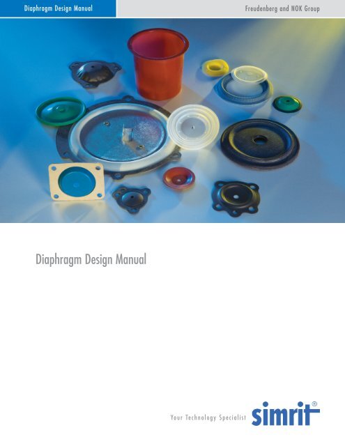
<strong>Diaphragm</strong> <strong>Design</strong> <strong>Manual</strong>Freudenberg and NOK Group<strong>Diaphragm</strong> <strong>Design</strong> <strong>Manual</strong>Yo u r Te c h n o l o g y S p e c i a l i s t
<strong>Simrit</strong> leads the industry in the design, testing, and production of dynamic seals, whetherthey are homogeneous, fabric-reinforced, or insert molded. <strong>Simrit</strong> supplies high quality productinto the Small Engine, Automotive, Irrigation, Gaseous Fuels Regulation and other markets andhas worked diligently to develop the elastomers required to meet these industry’s regulatorybodies (e.g. UL, NSF, FDA, etc.)We are particularly adept at working alongside the design team at the prototype stage and using<strong>Simrit</strong>’s quality and manufacturing systems, which are certified to ISO 9002 and QS 9000, youcan be assured that your design will result in a highly reliable production product.Using <strong>Simrit</strong>’s in-house diaphragm testing lab, our engineers can validate the design before,during, and after production has begun to continually improve the product. Each piece of testingequipment is built around a specific customer application to provide results that are easy tointerpret and immediately beneficial to our customer’s engineers. From life cycle testing tofailure mode analysis our engineering team can meet your challenge.<strong>Simrit</strong>’s production area uses the latest in manufacturing techniques to turn the designs into aproduction reality with a standard industry-leading lead-time of two weeks. <strong>Simrit</strong> supports avariety of inventory methods and customer order practices to make the decision to manufactureyour product with <strong>Simrit</strong> an easy one.The <strong>Simrit</strong> Team
Table of ContentsPageList of Tables, Figures, and Formulas 5Introduction 7<strong>Design</strong> Guideline – Initial <strong>Design</strong> ConsiderationsA “Quick Start” <strong>Design</strong> Check List 8Materials 10Elastomers 11General Purpose Elastomers - Oil ResistantEpichlorohydrin (ECO)Neoprene (CR)Nitrile (NBR or Buna-N)General Purpose Elastomers - Non-Oil ResistantButyl (IIR)Ethylene Propylene (EP or EPDM)Specialty ElastomersEthylene-acrylic (EA)Fluorosilicone (FVQM or FSI)Fluorocarbon (FKM)Polyacrylate (ACM)Silicone (VQM or SI)Fabrics 14General Purpose FabricsCottonNylon and PolyesterSpecialty FabricsFiberglassNomex TM and Kevlar TMOther Fabric Types<strong>Diaphragm</strong> Styles 16<strong>Diaphragm</strong> Construction Styles 17One Side Coated ConstructionTwo Side Coated ConstructionFlat <strong>Diaphragm</strong>s 18<strong>Design</strong> Guideline – Flat <strong>Diaphragm</strong> Stroke LimitsBlousingThe Trampoline SyndromeFlat <strong>Diaphragm</strong> – Closing CommentsFormed <strong>Diaphragm</strong>s 19<strong>Design</strong> Guideline – Min Convolution Width for One Side Coated Parts© Copyright FNGP 20092
FormulasFormula 1 – The <strong>Diaphragm</strong>’s <strong>Design</strong>ed Fabric Strength 15Formula 2 – Blousing Flat <strong>Diaphragm</strong>s for Stroke 19Formula 3 – Half Stroke for Convoluted <strong>Diaphragm</strong>s 21Formula 4 – Convolution Height for Convoluted <strong>Diaphragm</strong>s 22Formula 5 – Convolution Height for Deep Draw <strong>Diaphragm</strong>s 24Formula 6 – Half Stroke for Deep Draw <strong>Diaphragm</strong>s 24Formula 7 – The <strong>Diaphragm</strong>’s <strong>Design</strong>ed Effective Area 29Formula 8 – Calculating Sidewall Tension 31Formula 9 – <strong>Diaphragm</strong> <strong>Design</strong> Burst Strength 31Formula 10 – Piston Skirt Length for Best <strong>Diaphragm</strong> Support 34© Copyright FNGP 20096
IntroductionThe elastomeric diaphragm is a versatile dynamic seal that eliminates many of the limitations of othersealing methods.Elastomeric diaphragms do not leak, offer little friction and can be constructed for low-pressuresensitivity. With optimal material choices elastomeric diaphragms can withstand wide temperature andpressure variations without maintenance or lubrication.<strong>Diaphragm</strong>s are available in shapes ranging from flat to deep-drawn formed styles.Selecting the right geometry and materials for the application are only part of the equation. Thediaphragm’s associated assembly hardware is equally if not more important for improving its useful life.When embarking on the design of a device that will incorporate an elastomeric diaphragm seal as part ofits assembly, please use the Quick Start checklist and the Quick Reference Tabs as your road maps to arobust design.This manual has been organized into five main sections:Materials<strong>Diaphragm</strong> StylesSelected <strong>Design</strong> TopicsGlossary of TermsTechnical FlyersFor your convenience, the manual also includes an Engineering & Application Data Form, which is on thelast page, which can be used by you for your own design work or can be submitted to our EngineeringGroup, should you desire guidance in your diaphragm design.© Copyright FNGP 20097
<strong>Design</strong> Guideline – Initial <strong>Design</strong> Considerations – See Technical Flyer “<strong>Design</strong> for Manufacturing” Page 62A. Keep the convolution width as wide as safely possible.B. Provide enough space in the hardware to ensure smooth diaphragm movement.C. Whenever possible use a thinner and/or a more flexible material.D. Keep the stroke requirements as small as possible.The “Quick Start” Check List1. What is the diaphragm device’s basic function?a. Regulator – Pressure typically on one side.b. Pump – Pressure typically on both sides.c. Other.2. What are the environmental conditions? – See Page 44a. Temperature range.b. Humidity range.c. Ozone.d. Other.3. Which elastomer should be used? – See Pages 11–14, 15What fluid will contact the diaphragm?i. Passive – Such as distilled water or airii. Aggressive – Such as gasoline or solvents.4. Which fabric should be used, if any? – See Pages 14–15, 27, 30 & Technical Flyer Page 57What are the pressure requirements?i. Under 5 PSI – Fabric reinforcement may not be required.ii. 5 to 10 PSI - Fabric reinforcement will be application dependentiii. Above 10 PSI – Fabric reinforcement will be required.iv. Pressure differentials must be accounted for.v. Pressure spikes must be accounted for.5. Which construction style should be used? – See Pages 17 & Technical Flyer Page 59a. Pressure or aggressive media on one side?i. Should use a one side coated part.ii. May use a two side coated part.b. Pressure or aggressive media on both sides?i. Should not use a one side coated part.ii. Must use a two side coated part.c. What Is the expected stroke length?i. Short to medium? – Can use single or two side coatedii. Long? – Must use one side coated6. Which diaphragm shape should be used? – See Pages 16-24 & Technical Flyer Page 55a. Short stroke – Flat, Low Convoluted or Shallow Draw.b. Medium stroke – Shallow Draw, Convoluted or Drop Center.c. Long stroke – Deep Draw / Top Hat.7. What is the expected cycle rate?a. Test________________b. Use________________8. What is the expected cycle life?a. Test________________b. Use________________9. How will the diaphragm device be assembled? – See Pages 34-37a. Bolted piston and flange.b. Riveted piston and flange.c. Spin crimp or swage.d. Sonic welded.e. Housing:i. Injection molded plastic.ii. Stamped or formed metal.iii. Machined plastic or metal.10. Any additional hardware considerations?a. Return springs required? – See Page 30b. Positive stops required? – See Page 31c. Piston design? – See Pages 34d. <strong>Diaphragm</strong> care? – See Pages 3511. What style of flange will be needed? – See Pages 38-43a. Flat.b. Beaded.c. Gasketed.d. Combination.12. Any special specifications or requirements?a. FDA.© Copyright FNGP 20098
. UL.c. ASTM.d. Internal.e. Other.13. Tolerances – This area is often overlooked but is extremely important. Please review the information and thechart provided on pages 44-46 & Technical Flyer Page 60 before completing your design.Formula 1 – The <strong>Diaphragm</strong>’s <strong>Design</strong>ed Fabric Tensile Strength – page 15 Convolution Width x Burst Pr essureFabric Tensile ( <strong>Design</strong>) 2Formula 2 - Blousing Flat <strong>Diaphragm</strong>s for Stroke (reference Figure 1) – page 18 and 19 Bore Diameter Piston Diameter OD Bore Diameter 2 x S 2whereS Half Stroke2 Bore Diameter Piston Diameter 22Formula 3 – Half Stroke for Convoluted <strong>Diaphragm</strong>s – page 21Convoluted Half Stroke 2 x Height Convolution Width 2 xFormula 4 – Height Calculation for Convoluted <strong>Diaphragm</strong>s – page 22Flange Radius1Convoluted Height Convolution Width 2 x Flange RadiusFlange Thickness Half Stroke2Formula 5 – Height Calculation for Deep Draw <strong>Diaphragm</strong>s – page 24Deep Draw HeightFlangeRadius 1.56 ConvWidth Half Stroke Flange Thickness 2. SFFormula 6 – Half Stroke for Deep Draw <strong>Diaphragm</strong>s – page 24FlangeRadius 1.56 ConvWidth Deep Draw Half Stroke Height Flange Thickness 2.Formula 7 – The <strong>Diaphragm</strong>’s <strong>Design</strong>ed Effective Area – page 292 Piston Diameter CylinderDiameter Effective Area ( <strong>Design</strong>) x 4Formula 8 – Calculating Sidewall Tension – page 312 2.25 P D2 D 1Lbs.Total Tension(T) D1 of Bore CircumferenceCOSD2 in Where: D 1 = the piston diameter in inches, D 2 = the bore diameter in inches, P = the pressure in PSI, and a = the angle of thesidewall from the vertical. Note: D2 D1 12 Tan where h is h the height ofthe convolution at max strokeFormula 9 – The <strong>Diaphragm</strong>’s <strong>Design</strong>ed Burst Pressure – page 31 Fabric Tensile x 2 Burst Pr essure ( <strong>Design</strong>) Convolution Width Formula 10 – The Piston Skirt Length for Best <strong>Diaphragm</strong> Support – page 34Piston Skirt Length Convolution Height Half 2StrokeSF Cylinder DiameterSafety Factor (SF).25 / .99 1.00 / 2.50 2.51 / 4.00 4.01 and Up0.06 0.10 0.12 0.14© Copyright FNGP 20099
Tables KeyMeaning Excellent Very Good Good Fair PoorLetter A B C D E© Copyright FNGP 200910
ElastomersThe elastomer brings little strength to the diaphragm. Its primary function is to seal. Compound shouldbe chosen based on the environmental conditions, the cycle rates of the diaphragm, and the contactfluids. While making your decisions, please reference Tables 1, 2, and 4 in the Materials Section ofthe manual as well as the information provided on Thermal and Chemical Conditioning ofElastomers.General Purpose - Oil ResistantThree rubber compounds are considered general-purpose diaphragm materials -- Epichlorohydrin,Nitrile, and Neoprene. All are oil resistant and widely used in the automotive industry.Epicholorohydrin (ECO)Epicholorohydrin has an outstanding application temperature range. Its typical maximumconstant-use ceiling of 300°F is a 50° advantage over Neoprene and Nitrile. This issignificant, especially when considering automotive under-the-hood applications. The fuelresistance of Epicholorohydrin equals that of Nitrile.The low temperature properties of Epicholorohydrin allow it to have a minimum constantusetemperature of -40°F. This is unique in that the addition of plasticizers is not requiredto achieve this kind of low temperature flexibility. Therefore, thermal conditioning ofEpicholorohydrin has little effect on its flexibility.The ozone and weathering properties of Epicholorohydrin are equal to Neoprene. Thebasic mode of failure for ECO is reversion. Reversion is a softening of the material to theextent that rubber-like properties no longer exist; the material reverts back to what it wasprior to vulcanization. This happens when Epicholorohydrin is exposed to elevatedtemperatures (over 300°F) for very long periods of time.Neoprene (CR)Neoprene is similar to Nitrile in basic properties, but is not recommended for fuel relatedautomotive under hood applications. While it can be compounded for the same servicetemperatures as Nitrile, its main advantage is its natural resistance to ozone and weatherattack.Nitrile (NBR or Buna-N)Nitrile is perhaps one of the most widely used diaphragm elastomers due to its low costand its nearly universal properties. It is made of two polymers: butadiene and acrylonitrile.Adjusting the ratio of the two polymers can modify the oil resistance and low temperatureflexibility.For example, increasing the percentage of butadiene will improve the low temperatureflexing, but will lessen the oil resistance. The converse of this is true as well. Ozone andweathering resistance are weak attributes of this elastomer, but antioxidants can be addedto aid in this situation.© Copyright FNGP 200911
ButylCOMMON ELASTOMER COMPOUNDSName Advantages ASTM 1418 <strong>Design</strong>ation ASTM D2000<strong>Design</strong>ationLow permiation to many gases. OKin vegetable oil and oxidatingchemicals.IRBAEthylene-propyleneVery good hot water, low pressuresteam, and heat resistance.EP or EPDMCANeopreneGood oil, ozone, and weatherresistance. Good general purposematerial.CRBC or EBNitrileGood general purpose oil and fuelresistant material.NBRBF, BG, BK or CHEpichlorohydrinSimilar to nitrile with betterresistance heat aging and a widertemperture range. Also hasexcellent ozone resistance.ECOCH or DHPolyacrylate Oil and heat resistant to 350 o F.Good in transmission fluids.Ethylene-acrylic Oil and heat resistant to 350 o F.Good in transmission fluids. Betterlow temperature capability thanpolyacrylate.ACMEA or EAMDH or DFCHSiliconeGood dry heat resistance and lowtemperature. Good ozone andweather resistance.VMQGEFluorosiliconeOil and fuel resistant. Widetemperature range.FVMQFKFluorocarbonOil, fuel, solvent resistant.Excellent high temperature range.FKMHKTable 1 – Common Elastomer CompoundsGeneral Purpose - Non-oil ResistantButyl (IIR)An outstanding characteristic of Butyl is its natural low permeation rate to gasses. Thisfeature, however, can create problems in the molding process as it becomes difficult toeliminate any trapped air or gas.Ethylene Propylene (EP or EPDM)Ethylene propylene has good heat resistance up to 300ºF. It is often used in cold water,hot water, and low-pressure steam applications. Ethylene Propylene is also widely usedwith synthetic lubricants, automotive brake fluids and engine coolants.Specialty ElastomersEthylene-acrylic (EA)Ethylene-acrylic elastomer is used in automotive applications where their combinedproperties provide very good flex, ozone resistance, and high-temperature resistance alongwith fairly good low-temperature characteristics and oil resistance. The good dampeningcharacteristics of Ethylene-acrylic elastomers make it well suited for vibration mounts,pads, isolators, and so forth.© Copyright FNGP 200912
Fluorosilicone (FVQM or FSI)Fluorosilicones excel in high temperature resistance and to attack from fuels and oils. Also,due to fluorosilicone’s inherent low temperature properties, it will not shrink during “dryout”after being soaked in automotive fuels. Ozone resistance and weathering are alsooutstanding features of Fluorosilicone elastomers.One shortcoming of Fluorosilicones is their permeability to fuel vapor. Under the currentgovernment evaporative emissions regulations, fluorosilicone may not be a viable solutionfor all automotive under-hood fuel system sealing applications.Fluorocarbon (FKM)Fluorocarbons have the highest chemical resistance of today’s elastomers. In fuels and oilsthey also have the lowest volume swell. Because of their chemical resistance,Fluorocarbons are rapidly becoming the elastomer of choice in the fuel application field.Their stability at elevated temperatures is also excellent.The major drawback to Fluorocarbon elastomers is that their low temperature flexibility isgenerally poor, which can cause problems in overall diaphragm function. This is especiallytrue in applications where extreme temperature fluctuations are expected, such asautomotive under-hood applications during the winter months.In an effort to correct this problem, Fluorocarbon manufacturers have introduced a line ofcompounds with improved low temperature flexibility. They have typical recommendedservice temperature lows from -10ºF to 20ºF. Some of the newest variations will dry flex(no fluid contact) to -40ºF.Polyacrylate (ACM)Historically, conventional acrylic elastomers have been successfully utilized in a wide varietyof critical automotive seal applications. These include automatic-transmission seals, valvestemseals, crankshaft seals, pinion seals and oil-pan seals. The newer, more versatiletypes are also gaining rapid acceptance in other mechanical-goods applications such ashose, tubing, electrical-cable jacketing, rolls and belting.Silicone (VQM or SI)Silicone elastomers are often used when a broad temperature range is expected as it hasnatural low temperature flexibility. Silicone is not fuel or oil resistant. It does, however,exhibit some moderate chemical resistance. It can be compounded for low hysteresis (lowrolling resistance) where exceptionally flexible and sensitive diaphragms are required.© Copyright FNGP 200913
KEY PROPERTIES of COMMON ELASTOMER COMPOUNDSNameTypical ServiceTemperatureRangesAbrasionAcids -DiluteAlkalies -DiluteGasPermeabilityResistance To:CompressionSetHeat @212 o FOil(1)OzoneTearWater /SteamWeather HysteresisButyl -20 o F to +212 o F D C C C E B E A C B / B AEthylene-propylene -40 o F to +350 o F C A A D E A E A D B / A B CNeoprene -40 o F to +250 o F B A C D E B C C D D / C B BNitrile -40 o F to +250 o F C C C D C C B D C D / D E (2)Epichlorohydrin -30 o F to +300 o F D C D A C B B C D C / E C CPolyacrylate 0 o F to +350 o F D D D C E A B A E E / E BEthylene-acrylic -20 o F to +350 o F C C C A E A B B C B / E B CSilicone -80 o F to +450 o F E D E E C A D C E A / D A DFluorosilicone -65 o F to +375 o F E A A E D A A A E A / D A CFluorocarbon -10 o F to +400 o F C C C C C A A A D A / E A CNotes: (1) Oil Test - ASTM Oil #3, 70 hours @ 70 o C, (2) This result is for straight nitrile and can be improved through additives.Table 2 – Key Properties of Common Elastomer Compounds – Reference Key on page 10FabricsGeneral Purpose FabricsCottonCotton is used to some extent when special shape compliance is required and/or bulk is needed tomake thicker cross-sections.Nylon and PolyesterNylon and polyester fabrics are used for the majority of diaphragm applications. These fabrics areavailable in a variety of woven and knitted styles. Woven styles are normally used for shallow drawand/or high-pressure diaphragms. Knits, because of their high stretch capabilities, are usedprimarily for deep drawn diaphragms. Their lower strength capabilities are best suited fordiaphragms with low to moderate pressure requirements.Specialty FabricsFiberglassFiberglass fabrics are available and used, but are not generally recommended for diaphragmsbecause they can be extremely brittle. As the diaphragm functions, the glass fabric in the flexingarea of the diaphragm abrades on itself and can turn to powder, rendering the glass fabric nonproductive.Nomex TM and Kevlar TMNomex TM and Kevlar TM are of the aramid family and are related to nylon. Both can be used inextremely high temperature applications. Kevlar TM is unique because of its extremely high tensile© Copyright FNGP 200914
strength, but this strength also makes it difficult to process and hard to cut.Both Nomex TM and Kevlar TM are high performance materials. Price considerations in regard to theoverall application’s cost constraints should be considered before using them.FabricGENERAL CHARACTERISTICS of FABRICSTensileStrengthMoistureResistanceHeatResistanceMaximumOperatingTemperatureCotton D C D 350 o FNylon B B** C 300 o FPolyester C A B 350 o FNomex TM B B A 375/400 o FKevlar TM A B A 375/400 o FFiberglass A A A 500 o F+Notes: "A" is the highest possible rating wihtin a category., Nomex and Kevlar are registered tradmarks of DuPont., **Caution - hot water and steam hydrolyzes nylon.Table 3 – General Characteristics of Fabrics – Reference Key on page 10Other Fabric TypesIn addition to the fabrics listed above, several other fabric types are available for diaphragmreinforcement. They include silk for ultra thin, ultra sensitive diaphragms and non-woven orchopped fabric for reducing pressure or fluid wicking.Formula 1 – The <strong>Diaphragm</strong>’s <strong>Design</strong>ed Fabric Tensile Strength Convolution Width x Burst Pr essureFabric Tensile ( <strong>Design</strong>) 2ElastomerGENERAL CHEMICAL RESISTANCE to SOME COMMON CHEMICALSNitrileNeopreneButylSiliconeChemicalAir A A A A A B A A AAlcohols (General) B C B B BAntifreeze A A A B CBrake fluid A BButane A A C B A BCitric acid A C B B C C C C CDiesel oil A A C B A AFruit juice A A A A C B BGasoline, automotive A A B B CHydraulic oil (petro) A B B B C B BNatural gas A A A B C B B B BSalt water A A A A C C B BNote: A blank space means Not Rated or insufficient data available.EthylenepropyleneFluorocarbonPolyacrylateFluorosiliconeEpichlorohydrinEthyleneacrylicTable 4 – Elastomer Resistance to Some Common Chemicals – Reference Key on page 10© Copyright FNGP 200915
<strong>Diaphragm</strong> StylesDeep Draw with ID and Flange Holes – See page 23Shallow Draw with Beaded Flange – See page 20Convoluted with Flat Flange – See page 21Flat Cut with ID and OD Holes – See page 18Double Taper with Flat Flange – See page 24Drop Center with Piston Hole – See page 22© Copyright FNGP 200916
<strong>Diaphragm</strong> Construction StylesBefore the topic changes to the geometric diaphragm styles available, a word or two about diaphragmconstruction styles is necessary. Up to this point we have been discussing the elastomers and supportingfabrics as separate components. To construct a diaphragm, elastomer and fabric components must bebrought together in one of the following forms:One Side Coated ConstructionThe main advantage to the one side coated construction is the ability to mix and match variousfabrics and elastomers in small runs for specialty applications. Due to this material flexibility, oneside coated parts can use fabrics and elastomers not normally available for two side coatedconstruction.In addition to this, one side coated parts can be formed with taller, narrower, convolutions and canbe easily made with various sealing features (e.g.: beads, v-ribs, etc.). One side coated constructionis also commonly referred to as lay-up or single coat construction.Two Side Coated ConstructionThe main reason for considering two side coated construction is that it gives excellent protection tothe reinforcing fabric, provides a seal on both sides of the diaphragm in reverse pressure applicationsand reduces abrasion wear.Two side coated construction comes in two distinct styles: as a coated fabric and as a molded doublecoat. <strong>Diaphragm</strong>s made via a two side coated construction are sometimes referred to as doublecoated.The advantages and disadvantages of these two construction styles are compared in Table 5 below.Two Side Coated Construction Styles ComparisonConstruction Advantages DisadvantagesCoated Fabric 1 Thin sensitive cross-section 1 Limited availability ofmaterial combinations2 Lower tooling cost 2 Large minimum material runs3 Lower manufacturing cost 3 Limited geometric features(e. g.: height, beads)Molded Double Coat1 More robust geometric1 Higher tooling costfeatures - similar to singlecoat2 Limitless elastomer and2 Higher manufacturing costfabric combinations3 Small order minimums 3 Less sensitivity4 Limited production volumesTable 5 – Two Side Coated Construction Styles Comparison© Copyright FNGP 200917
Flat <strong>Diaphragm</strong>sFlat diaphragms are an economical way to incorporate a diaphragm into an application. Simply put,flat diaphragms are shapes, typically round, cut from a roll of diaphragm material.A flat diaphragm’s main limitation is stroke length. This limitation can be overcome, to some degree,by blousing (also see <strong>Design</strong> Guideline – Flat <strong>Diaphragm</strong> Stroke Limits), but a flat diaphragmshould not be considered as an inexpensive substitute for a properly engineered formed diaphragm.HalfStrokeFlange DiameterCylinder (Bore) DiameterPiston DiameterFullStroke12°Figure 1 – Flat <strong>Diaphragm</strong> – Shown in an Up Stoke PositionTypical applications for flat diaphragms are high-pressure regulators; gage protectors and somediaphragm pump styles.<strong>Design</strong> Guideline – Flat <strong>Diaphragm</strong> Stroke LimitsThe expected half stroke, the part of the stroke that’s above or below the neutralplane of the flange of a flat diaphragm, can be determined by limiting the angleof deflection between the flange plane and the piston assembly to 12º (seeFigure 1).The minimum convolution width should not be less than 1/8”. The maximumstroke capability of the diaphragm would then be twice the deflection from theflange plane. Due to the wide variety of diaphragm applications, this informationshould be considered a starting point only.BlousingBlousing is a way to provide a flat diaphragm with enough slack for stroking. Creating slack or“blouse” material in a flat diaphragm can be handled in a couple of ways. In the case of boltedflange mountings, the bolt circle can be slightly larger in the diaphragm than on the housing. If thepart is round and crimped at the OD, the diaphragm should be made larger than the OD (seeFormula 2 below).This same approach would be followed to find the minimum bolt circle diameter needed if you plan touse a bolted flange to capture your diaphragm OD.© Copyright FNGP 200918
Formula 2 - Blousing Flat <strong>Diaphragm</strong>s for Stroke (reference Figure 1) Bore Diameter Piston Diameter OD Bore Diameter 2 x S 2whereS HalfStroke2 Bore Diameter Piston Diameter 22The Trampoline SyndromeThis phenomenon is typical of a diaphragm stretched during assembly instead of being bloused.What results is a bouncing or spring type of action requiring more energy from the system to startthe stroke. In all but a few cases, this type of diaphragm interference is unwanted and should beavoided.Flat <strong>Diaphragm</strong>s - Closing CommentsRubber under stress most often reacts by taking a set, which is almost always a result of stretching.Often when removing a diaphragm after use, the diaphragm will have formed a convolution. Thischange results in a lessening of the energy required to activate the diaphragm and can change theeffective area, which can result in set point changes. If there is concern that these kinds of changesare going to present problems in your application, it may be best to design your application around aformed diaphragm.Formed <strong>Diaphragm</strong>sMany of the problems associated with flat diaphragms can be overcome by using a formed diaphragm.The primary advantages of formed diaphragms are their application versatility (see Technical FlyerPage 55 for additional insight on this topic). There are several basic types of formed diaphragms andthey are detailed in the following sections in the order of their stroke capability – minimum to maximum:Many of the formed styles, with the notable exception of the deep draw, can be made as two sidecoated. For deep draw styles it is often necessary to produce these parts in a one side coatedconstruction.One side coated construction is where the chosen fabric and elastomer are brought together at the moldto form the finished part. The main difference between one side coated construction and two side coatedconstruction is that in one side coated construction the fabric has 90 to 95% of the elastomer on one sideand only 5% to 10% on the other. A one side coated diaphragm is designed for use with the system’shighest pressure on its elastomer side only.Pressure reversals, or pressure on the fabric side of a one side coated diaphragm, can blow the elastomeroff the fabric causing a failure. Occasional or momentary pressure spikes may not be a problem, butconsistently repeating ones will be.<strong>Simrit</strong>’s team of diaphragm engineers is ready to guide you to the best diaphragm solution for yourapplication needs, regardless of construction.© Copyright FNGP 200919
<strong>Design</strong> Guideline – Minimum Convolution Width for One Side Coated PartsThe minimum convolution width for one side coated parts is generally accepted to be four timesthe thickness of the diaphragm’s convolution.Shallow Draw, Dish or Pie Pan Style - Figure 2:As the name implies, this formed style looks very much like a pie pan. Shallow draw diaphragms areused for strokes just beyond the range of flat diaphragms.FlashFlangeRadiusFabricSideCylinder DiameterPiston DiameterPistonRadiusBeadHeightHeightBead WidthPiston AreaThicknessSidewall ThicknessFlangeThicknessBead DiameterFigure 2 – Beaded Shallow Draw <strong>Diaphragm</strong> – See Section on Beads for additional InformationThe advantage here is easier assembly and no blousing. For longer stroke requirements refer todeep draw styles.Cylinder Diameter (CD) .25" / .99" 1.00" / 2.50"Piston Area Thickness .015" .017"Flange Area Thickness .015" .017"Convolution Thickness .015" .017"Piston Radius .094" .125"Flange Radius .031" .063"Flange Diameter (Typ) CD + .75" CD + 1"2.51" / 4.00" 4.01" / 8.00" 8.01" & Up.024" .035" .045".024" .035" .045".024" .035" .045".156" .250" .250".094" .125" .125"CD + 1.5" CD + 2" CD + 2"Table 6 – Dimensional Guidelines for Shallow Draw <strong>Diaphragm</strong>s© Copyright FNGP 200920
Convoluted Style - Figure 3:This formed style also has stroke capabilities slightly greater than flat diaphragms. A convolutedstyle diaphragm is one that has the clamping flange and the piston area on the same plane.Convoluted diaphragms are best known for their responsiveness and are well suited to applicationsrequiring stable set points such as regulators. Convoluted styles exhibit very low hysteresis.Figure 3 – Convoluted <strong>Diaphragm</strong>FlangeRadiusFabricSideCylinder DiameterPiston DiameterPistonRadiusConvolutionThicknessHeightFlangeThicknessPiston AreaThicknessFlange Diameter<strong>Design</strong> Guideline – Convoluted Stroke Limit for Two Side Coated PartsFor two side coated, convoluted parts the suggested total stroke length is 2.13 times theconvolution width.This limitation does not apply to one side coated formed parts.Cylinder Diameter (CD) .25" / .99" 1.00" / 2.50" 2.51" / 4.00" 4.01" / 8.00" 8.01" & UpPiston Area Thickness .015" .017" .024" .035" .045"Flange Area Thickness .015" .017" .024" .035" .045"Convolution Thickness .015" .017" .024" .035" .045"Piston Radius .031" .063" .094" .125" .125"Flange Radius .031" .063" .094" .125" .125"Flange Diameter (Typ) CD + .75" CD + 1" CD + 1.5" CD + 2" CD + 2"Table 7 – Dimensional Guidelines for Convoluted and Drop Center <strong>Diaphragm</strong>sFormula 3 – Half Stroke for Convoluted <strong>Diaphragm</strong>sConvoluted Half Stroke 2 x Height Convolution Width 2 xFlange Radius© Copyright FNGP 200921
Formula 4 – Height Calculation for Convoluted <strong>Diaphragm</strong>s1Convoluted Height ConvolutionWidth 2 x Flange RadiusFlange Thickness Half Stroke2Drop Center or Offset Convolution Style - Figure 4:Drop center formed diaphragms are convoluted diaphragms with a deeper center draw. This stylehas all the advantages of the convoluted style with longer stroke capability. Drop center styles canalso be easier to assemble than convoluted styles, particularly if a return spring or some otherhardware limitation doesn’t allow the piston surface and the flange to be on the same plane duringassembly. Please reference Table 7 for dimensional guidelines.OffsetHeightFabric SideFlangeRadiusCylinder DiameterPiston DiameterPistonRadiusConvolutionThicknessFlangeThicknessPiston AreaThicknessFlange DiameterFigure 4 – Drop Center <strong>Diaphragm</strong><strong>Design</strong> Guideline – Drop Center Stroke Limit for Two Side Coated PartsFor two side coated, drop center parts the suggested total stroke length is 3.7 times theconvolution width.This limitation does not apply to one side coated formed parts.Deep Draw or “Top Hat” Style - Figure 6:Deep draw formed diaphragms have the longest available stroke lengths among diaphragmgeometries. Their stroke capabilities are only limited by the chosen reinforcing fabric’s ability to beconformed to the necessary shape. Before assembly, deep draw diaphragms must be manuallyformed into the shape of a tall, convoluted diaphragm so they will roll properly (reference Figure 5).© Copyright FNGP 200922
One issue with deep draw diaphragms is that they can occasionally invert in the convolution area asthey cycle. Using an appropriately designed piston along with a curved lip retainer plate to lock thepiston and radii of the diaphragm to the hardware can control this issue.Curve LipRetainerPistonSkirtFigure 5 – <strong>Diaphragm</strong> Assembly With a Curved Lip Retainer<strong>Design</strong> Guideline – Deep Draw Maximum Convolution HeightThe maximum recommended stroke length for deep draw diaphragms is determined bykeeping the height of the diaphragm less than, or equal to, the diameter of the bore.For best functional results, these styles must be used with well-guided pistons andsupported by sufficiently long piston skirts.PistonRadiusCylinder DiameterPiston DiameterFabricSideFlangeRadiusPiston AreaThicknessHeightFlangeThicknessFlange DiameterSidewallThicknessFigure 6 – Deep Draw <strong>Diaphragm</strong>Cylinder Diameter (CD) .25" / .99" 1.00" / 2.50" 2.51" / 4.00" 4.01" / 8.00" 8.01" & UpPiston Area Thickness .015" .017" .024" .035" .045"Flange Area Thickness .015" .017" .024" .035" .045"Convolution Thickness .015" .017" .024" .035" .045"Piston Radius .094" .125" .156" .250" .250"Flange Radius .031" .063" .094" .125" .125"Flange Diameter (Typ) CD + .75" CD + 1" CD + 1.5" CD + 2" CD + 2"Table 8 – Dimensional Guidelines for Deep Draw <strong>Diaphragm</strong>s© Copyright FNGP 200923
Formula 5 – Height Calculation for Deep Draw <strong>Diaphragm</strong>sDeep Draw HeightFlangeRadius 1.56 ConvWidth Half Stroke Flange Thickness 2.SF Formula 6 – Half Stroke for Deep Draw <strong>Diaphragm</strong>sDeep Draw HalfStrokeFlangeRadius 1.56 ConvWidth Height Flange Thickness 2.SF Cylinder DiameterSafety Factor (SF)Table 9 – Calculation Safety Factors.25 / .99 1.00 / 2.50 2.51 / 4.00 4.01 and Up0.06 0.10 0.12 0.14Double Tapered Deep Draw Style - Figure 7:As a way of reducing the Circumferential Compression a rolling convolution normally goesthrough during its stroke cycle, a standard deep draw diaphragm can be augmented with a secondtaper. By adding this second taper, the main sidewall angle is greatly reduced thereby reducing thecircumferential compression increasing the life of the diaphragm.Please also review the discussions on Circumferential Compression and The Effective Area of<strong>Diaphragm</strong>s in the Selected <strong>Design</strong> Topics section for additional information.Due to the wide variety of options,please contact <strong>Simrit</strong> for dimensionaldetails on double taper diaphragmsFigure 7 – A Typical Double Taper <strong>Diaphragm</strong>Alternate <strong>Diaphragm</strong> ConstructionsAll formed diaphragm styles can be made with or without: Fabric Added Sealing Features Gasketing Inserts, and CladdingEach of these options are further detailed in the next section, Selected <strong>Design</strong> Topics.© Copyright FNGP 200924
Selected <strong>Design</strong> TopicsCommon Causes for Non-Linear Stroking1. Yarn geometry within the fabric.2. Return spring not seated or not flat ground.3. Insufficient bearing support of the piston rod.4. Spring coil diameter too small for piston.5. Piston height too low. Does not support the diaphragm sidewall.6. Convolution width too wide.See page 27Common Causes for Residual Stresses1. Hot creased parts.2. Uneven draw of fabric in preforming or molding.3. Old or nervy compound4. Excessive precure time on coated fabric or compound.5. Excessive post-curing of parts.6. Molded at too high a pressure, or mold overloaded with compound.7. Bad packaging.8. Under cure of the rubber.See page 32The Three Most Common Types of Bead Failures:1. Not enough compression, which can result in flangeleakage.2. Over compression which can cause a cut in thebead or the diaphragm.3. Over compression can cause the bead material toflow back into the diaphragm convolution causingincreased stress and potential premature failure.See page 39Advantages of Tear Drop Beads:1. Provides for a more even draw of the fabric onto thediaphragm. While smoothing out possible wrinkles, italso aids in keeping the fabric in place within the part.2. Provides for a positive location of the part in the trimdie, which controls the concentricity.3. Provides for backpressure in the mold to allowpositive flow of the rubber and flushes out trappedgasses in the bead.See page 40© Copyright FNGP 200925
Ideal <strong>Diaphragm</strong> Thickness<strong>Design</strong> Guideline – The Ideal <strong>Diaphragm</strong> ThicknessAs the saying often goes, “If a little is good, a lot must be better!” In fact, theopposite is typically true when it applies to diaphragm thickness.Historically, engineers have tried to overcome higher pressures by adding morethickness to the diaphragm, especially non-reinforced diaphragms.The guideline is, “design your diaphragm as thin as safely possible.” Thinnerdiaphragms roll easier and are more responsive to small pressure changes.Another concern surrounding excessively thick part cross-sections is what happens to the “excess”elastomer when the part is compressed during assembly (reference section on Flange Sealing –Material Compression for additional details). The excess elastomer extrudes into the convolution areaforming a thicker “bead-like” cross-section just inside the bore diameter or just outside the pistondiameter. The addition of this “bead,” or thicker cross-section will make the diaphragm more vulnerableto flex failure.Soft elastomers tend to extrude more easily while firm elastomers exhibit a higher modulus of elasticityand are not so easily extruded. One caution is that diaphragms made from higher modulus elastomerscan have reduced flexibility.<strong>Diaphragm</strong> Convolution (Sidewall) ActionFigure 8 shows the cross section of the convolution in three positions. Please note that point A is anarbitrary position on the convolution, selected only for illustration purposes.AA 1A 2Figure 8 – Convolution / Sidewall Action - Showing the Movement of a Point on a <strong>Diaphragm</strong>’s ConvolutionThe points A 1 and A 2 are at the same location as point A on the convolution. Their position change is dueto the rolling action of the convolution. The diameter of the convolution moves inward on the upstroke,and outward on the return stroke. Activation pressure applied to the system shapes the rollingconvolution within the confines of the piston and bore.The configuration of the convolution curve closely resembles a catenary curve, regardless of its previousmolded shape. During the positive or working part of the stroke, the convolution material is rolling away© Copyright FNGP 200926
from the piston in an expansion mode. During this movement, the fabric reinforcement controls anyradial stretching.On the return stroke, the material is rolling toward the piston. In this mode the material will compress,as it is moving into a smaller diameter. The differences in circumference of both positions will be anindication of how much material will either have to be squeezed or folded over to conform to the spacebetween the piston and sidewall. The concern is that the constricting forces will cause radial creases onthe sidewall.On the up stroke the full pressure is across the convolution stretching the material. However, on thereturn stroke, the pressure drops off and the energy in the return system (typically a spring) becomes thedominating force in returning the piston to its original position. Often there may not be sufficientpressure across the diaphragm to prevent wrinkles.In cases like this, the wrinkles can become creases and the creases can become failure points. Thisphenomenon is referred to as cornering because of the fold or seam that forms at the failure point.Guiding the PistonA diaphragm piston assembly does not normally travel at right angles to its movement axis unless it iswell guided. Sometimes during very slow stroke rates the piston may actually appear to wobble. Duringrapid stroking, the wobble can become disruptive or even a destructive oscillation as one side of thepiston tips during its travel. Positive linear stroking of the piston will lead to better system function andlonger diaphragm life.<strong>Diaphragm</strong>s with generous flange, piston, and convolution radii will support an easy rolling action and thewobble should not create any harmful effects on the diaphragm.Common Causes for Non-Linear Stroking1. Yarn geometry within the fabric.2. Return spring not seated or not flat ground.3. Insufficient bearing support of the piston rod.4. Spring coil diameter too small for piston.5. Piston height too low. Does not support the diaphragm sidewall.6. Convolution width too wide.The Effects of Fabric GeometryTable 10 – Common Causes for Non-Linear StrokingFabric geometry refers to the type of weave, yarn count, and construction style of the yarns. Thesecharacteristics are inherent to any woven fabric. Most fabrics used for diaphragm reinforcement aresquare woven. Square woven fabrics have the same number of threads in the warp direction (the lengthof the fabric) as is in the fill direction (the width of the fabric). The yarns also have the sameconstruction and weight.Formed diaphragms typically have a circular working area. Four directions within the working area willhave yarns running straight from the center of the diaphragm to the OD. Fabric being stressed in thedirection of these yarns will exhibit little or no stretch (Refer to Figure 9).© Copyright FNGP 200927
In the locations 45 o to these straight runs, the yarns are on the diagonal or bias of the fabric. With stresson the bias (Refer again to Figure 9), yarns want to divert in the direction of the stress. They becomeskewed to each other and the fabric elongates. This elongation can be seen as the yarns gathertogether.Figure 9 – Fabric Skew Due to FormingThe amount of variable elongation in the diaphragm convolution or sidewall will be directly related to theangular change between the straight yarns and the bias yarns.A flat reinforced diaphragm will react like a formed diaphragm to the application of stress. Sections ofthe working area will react and respond differently to the pressure differential. The section with theyarns skewed will appear to bulge, producing a slack, delaying the response to the piston. On the otherhand the section with the yarns still at right angles will act immediately upon the piston.In summary, the material composition within the convolution varies due to the directional nature of theyarns and skewing or distortion of the yarns during molding. Therefore, each individual section reactsdifferently to pressure when being stroked. This is much more pronounced in large diaphragms and slowacting devices.The Effective Area of <strong>Diaphragm</strong>sFor all practical purposes, the effective area of a conventional piston device is the area of the pistonitself. The clearance between the bore and piston is usually only large enough to contain a compressiontype seal, i.e. o-ring, packing, etc.By comparison, a diaphragm device requires a much larger clearance to provide space for the activeportion of the diaphragm, the convolution. The convolution bridges the gap between the housing andthe piston and functions as a flexible seal.When an 180º convolution is formed, or if the flange and piston are in the same plane, the effective areais calculated by using the midpoint diameter bounded by the piston and bore (see Figure 10). In theabsence of the 180º convolution, the effective area would vary from a maximum as defined by the borediameter, to a minimum as defined by the piston diameter.© Copyright FNGP 200928
Figure 10 – The Changing Effective DiameterIn the past, considerable emphasis was placed on using diaphragms to produce a constant effective areathroughout the useful stroke. With the addition of more convolution height and a narrower piston-boregap, 180º convolutions could be accomplished. This approach did not produce the most durablediaphragms. The rolling of the material through tight radii at the top of the convolution increases internalfriction and raises the potential for compression cracks.In the final analysis, the maximum area change that could be realized would be the difference in the areaof the piston and the area of the bore. Tests on diaphragms with less than an 180º convolution, underlight pressure, featured some measurable changes in effective area.Conversely, these same parts showed no measurable changes when higher pressures were introduced aslong as there was some semblance of a curve in the convolution during the stroke.While a changing effective area can have some negative affect on diaphragms required to be functionalat extremely low pressures (inches of water), practical applications have shown that it is often moreadvantageous to utilize diaphragms with lower, wider convolutions and gentle blending radii to reducestresses, than to worry about its potential change in effective area.Devices requiring return springs are one limitation to this approach and this circumstance is furtherdeveloped in the next section.Formula 7 – The <strong>Diaphragm</strong>’s <strong>Design</strong>ed Effective Area Piston Diameter CylinderDiameter Effective Area ( <strong>Design</strong>) 42x © Copyright FNGP 200929
The Effects of The Return SpringIn most diaphragm applications a return spring is used in the assembly to ensure that the diaphragmresets itself to its home position. During a typical assembly the spring is compressed slightly against thepiston adding a preload. This compression creates a slight negative force on the diaphragm requiring apressure greater than the preload to move it. The influence of this preload on the diaphragm is areduction in the net effective area.This change in effective area caused by the return spring far exceeds anything achievable by thediaphragm alone. Additionally, the potential energy within the spring is responsible for a major share ofthe hysteresis in the diaphragm device. This issue can be especially troublesome on diaphragm devicesrequired to function at very light pressures (inches of water).<strong>Diaphragm</strong> Strength RequirementsIn determining the amount of force the diaphragm will have to tolerate, keep in mind any springs oradditional forces that have to be overcome. These forces may have to be estimated but they must beadded to the primary requirements.Along with any additional forces, the designer must keep in mind the space available for the applicationhardware and its effect on the size of the diaphragm. If space is severely restricted, the system pressuremay have to be increased to allow for the diaphragm to properly actuate in the application. Increasingthe pressure will impact the tension and burst requirements of the convolution and its fabricreinforcement.The tension of the convolution sidewall is dynamic during the diaphragm’s stroke phase, as wasdemonstrated in Figure 8 as point A moved to point A 2 . For calculating the sidewall strengthrequirements we will concentrate on the worst-case scenario, which is when the diaphragm has reachedthe end of its stroke capability and the diaphragm material stops the motion of the piston – which is notrecommended (see Figure 11).Figure 11 - <strong>Diaphragm</strong> Strength - Assembly Illustration for Formula 8© Copyright FNGP 200930
In this worst-case scenario, the total sidewall tension is made up of two components:1) The tension prompted by the pressure acting upon thepiston portion to the system.2) The tension generated by the pressure acting on theconvolution area. lbs. The forces are converted to the peripheral in for each area and added.Formula 8 – Calculating Sidewall Tension.25 P Total Tension(T) DCOS 2 2D2 D 1Lbs.ofBore Circumference1D 2Where: D 1 = the piston diameter in inches, D 2 = the bore diameter in inches, P = the pressure in PSI,and a = the angle of the sidewall from the verticalNote: Tan1 D2 D12h where h isthe height ofFormula 9 – The <strong>Diaphragm</strong>’s <strong>Design</strong>ed Burst Pressure Fabric Tensile x 2 Burst Pr essure ( <strong>Design</strong>) Convolution Widthinthe convolution at max strokeFor most applications the designed burst pressure should be at least 4 times the expected workingpressure of the application.Positive StopsTo ensure that the diaphragm never sees the kind of destructive tension noted in the previous section, apositive stop (see Figure 12) should be incorporated into the system. Positive stops are design toprevent the diaphragm material from acting as a brake for the piston’s movement and thereby helping toincrease the diaphragm’s cycle life.Stops can also be added to a portion of the assembly outside of the diaphragm chamber, such as on thepiston rod.© Copyright FNGP 200931
Positive stops should be added to both sides of the piston for double acting diaphragm systems.Figure 12 – Two Types of Positive StopsResidual StressesThere are additional issues that come under the mantle of stresses that are not part of design problems.Such issues are encountered by the fabricator of the diaphragms and can be classified as residualstresses. These stresses often manifest themselves as distorted parts. Table 11 shows some of thecommon causes for residual stresses.While it is the responsibility of the manufacturer to deal with these issues, they need to be considered byall parties, as they can be a result of diaphragm shape, the manufacturing process required or theapplication’s required elastomer and fabric combination.Common Causes for Residual Stresses1. Hot creased parts.2. Uneven draw of fabric in preforming or molding.3. Old or nervy compound4. Excessive precure time on coated fabric or compound.5. Excessive post-curing of parts.6. Molded at too high a pressure, or mold overloaded with compound.7. Bad packaging.8. Under cure of the rubber.Table 11 – Common Causes for Residual StressesEnhancements for Improving Stroke LifeAttention to design detail can greatly enhance the stroke life of a diaphragm. Keeping the mating partsas smooth as possible will offer some of the greatest gains. All mating hardware surfaces should be norougher than 32 micro inches and in high-cycle applications a 16 micro inch surface is recommended.Lubricating the moving surfaces of the diaphragm with molybdenum disulfide or the piston with Teflon TM© Copyright FNGP 200932
prior to assembly can also help reduce abrasion and increase stroke life.Three additional keys to stroke life longevity are:1) Making sure that the piston assembly is well guided (as previously noted) to minimizecocking or wobble (see Figure 13).2) Ensuring that the system is properly vented or that the change in pressure direction acrossthe diaphragm is such that it eliminates the possibility of backpressure and the resultingreversal of the convolution (see Figure 14).3) Eliminating circumferential compression of the convolution.Figure 13 – Effects of a Cocked PistonFigure 14 – Effects of Reversed PressureCircumferential CompressionCircumferential compression results from the larger convolution diameters being compressed around thesmaller diameters of the piston. This compression causes folds in the convolution and this continualaction of forming and un-forming these folds will eventually cause the fabric, and ultimately thediaphragm, to rupture.The tell tale sign of this problem is often referred to as cornering or “four cornering,” as diaphragms thatare experiencing circumferential compression in their convolution or sidewall will often exhibit fourequally spaced folds.Circumferential compression typically occurs in the longer stroke, top hat style diaphragms. Two ways tolessen the circumferential compression effect are:1) Lower the stroke requirements so that a convoluted diaphragm can be used (in the downstrokedirection only).2) Use a double tapered diaphragm (see Figure 7 in the <strong>Diaphragm</strong> Styles section).© Copyright FNGP 200933
Please also review the <strong>Diaphragm</strong> Convolution (Sidewall) Action section of this manual foradditional insight into this phenomenon.Piston <strong>Design</strong> CriteriaSizeIn sizing the piston for your application the initial assumption should always be that the requiredeffective system diameter is the piston outside diameter. This approach will help compensate forthe energy loss due to internal friction within the system itself. It also eliminates some of themessy issues associated with a fluctuating effective area (see the section on Effective Area).Length (Piston “Skirt”)When considering the length of the piston, often referred to as the piston skirt, the designermust keep in mind the movement of the convolution during the stroke cycle. While almost anyskirt length may work in principle, best design practices call for the skirt to be long enough tosupport the convolution during all phases of the stroke cycle (reference Figure 15). At no timeshould the convolution be able to expand or move beyond to top edge of the skirt.Extending the length of the skirt can also offer the designer one option for a positive stop, whichwill help protect the diaphragm from over stroke (reference Figure 16).Formula 10 – The Piston Skirt Length for Best <strong>Diaphragm</strong> SupportShapePiston Skirt Length Convolution Height Half 2StrokeMost applications will call for a round piston with a piston skirt, designed to support thediaphragm’s sidewall throughout its stroke length (reference Figure 15). To ensure a proper fit,the radius on the base of the piston must match the piston radius of the diaphragm.Figure 15 – Proper Piston to Convolution Support vs. Poor SupportPlease refer to the part figures in the <strong>Diaphragm</strong> Styles section of this design guide for thelocation of the diaphragm’s piston radius.In cases where a special piston shape may be required, please consult with our team ofdiaphragm design engineers for the optimum shape and attachment method.© Copyright FNGP 200934
The Care and Housing of <strong>Diaphragm</strong>sAs noted in the manual’s introduction, the hardware that captures and surrounds the diaphragm is asimportant to the success of the application as the elastomer, fabric, and geometry. These surrounding ormating parts must be compatible with the diaphragm in every way; otherwise performance and cycle lifewill suffer.First and foremost all hardware that contacts the diaphragm must be as smooth as possible and burr free(see the section on Enhancements for Improving Stroke Life).The second most important requirement is that all mating hardware match the diaphragm’s geometryand capture it in such a way as not to distort it while allowing for free movement of the convolution. Anyinduced distortion in the diaphragm can affect the rolling action of the convolution, add additionalstresses or create wrinkles.Figure 16 – A Typical Deep-Draw <strong>Diaphragm</strong> Assembly with a Return Spring and Positive StopTo minimize distortion during assembly, some consideration should be given to using jigs and fixtures tocompress return and / or balance springs, align housing halves and support the diaphragm. One methodof rendering support to the diaphragm during assembly would be to inflate it with a steady stream oflow-pressure air.If the method of housing assembly includes screwing one piece of hardware into another with thediaphragm captured between them, some form of thrust washer should be considered to eliminate anytwist or wrinkling.This hardware and assembly discussion is further expanded on in the section titled Flange Sealing.Transition RadiiThe transition radii are the features on the diaphragm that help define the shape of theconvolution by connecting it to the flange and the piston surfaces. For all practical purposesthese radii should never be less than .015”.© Copyright FNGP 200935
As with all hardware surfaces, the corresponding radii on the hardware must also be the same asthose on the diaphragm and must be as smooth as possible.Please reference Figures 2, 3, 4, and 6 along with Tables 6, 7, and 9 for illustrations andrecommended sizes of transition radii.Assembly IssuesMaterial CompressionOne of the more reoccurring causes for diaphragm failure and poor performance can beattributed to the compression of the diaphragm during assembly. Proper compression is requiredto affect a long lasting seal in both the piston and flange areas.The typical failure modes are over-compression, leading to flex failure, or under-compression,leading to leakage. The root cause of the problem stems from the difficulty in controlling thecompression on the diaphragm’s sealing surfaces during assembly.The elastomer portion of the diaphragm can only support a limited amount of compression. Inan over-compression situation the assembly load exceeds the compression resistance of theelastomer and extrudes elastomer out to unclamped areas of the diaphragm.In an under-compression situation, the assembly load is too light and does not approach thenormal compression limit of the elastomer for an effective seal.The challenge facing the designer is the difficulty in determining what the proper loading shouldbe for their particular application. Further exacerbating the loading issue is the effect oftemperature and / or fluid on the compression set properties of the elastomer (see the section onthe Effects of the Application Environment for more details).To maintain a stable compression set and therefore a proper seal the loading capacity of theelastomer must not deteriorate.Due to the wide variety of applications and available elastomers, it is often necessary to do a cut-In order to arrive at an appropriate amount of flange compression via thisand-try method.method:1) The material must be tested while under compression2) Various temperatures must be tried3) Several suitable contact test fluids must be usedIn the past designers attempted to solve compression related sealing issues by designing thickerparts (see <strong>Design</strong> Guideline – The Ideal <strong>Diaphragm</strong> Thickness at the beginning of thissection for more on this point).Assembly Specific IssuesScrewed and BoltedIf screws or bolts are planned for holding the assembly together, a torque requirementwill have to be determined in order to produce the optimum loading. Here again, the© Copyright FNGP 200936
cut-and-try method may be the best development alternative.Any perforations through the diaphragm used for attaching hardware (flange or piston)should be located such that there is at least .100 to .125 inches of material between theedge of the perforation and the next hole or trim edge.It is equally important to keep the mounting perforations away from the flange or pistoncorner radii to improve clamping seal and reduce the opportunity for potential leaks. Asa starting point the minimum distance should be .100 to .125 inches at pressures lessthan 50 psi and increase as pressures increase.Please refer to Figure 17 and Table 11 for additional information on minimum sealingarea for bolted piston and flange hardware.Max SystemPressure (psi)0 - 50 51 - 150 151 - 300 301 - 500Minimum SealingArea(length from radius toperforation in inches).100 .150 .200 .250Table 12 – Minimum Clamp Area for Bolted Pistons and FlangesFigure 17 – Clamp Area for Bolted Pistons and Flanges© Copyright FNGP 200937
Additional StylesThese same compression issues and solution approaches apply to all other forms ofhardware assembly such as crimped, swaged and spun metal parts as well as sonicwelded, glued or snap fit plastic parts.Please feel free to contact <strong>Simrit</strong>’s Engineering Group to discuss these and other methodsfor proper diaphragm capture in your assemblyTypical Assembly Challenges and Suggested Solutions1) Bending of the material in the flange between the bolts. Adding more bolts, thusreducing the distance between them, can usually make a correction. Increasing thethickness in the hardware flange material will also reduce the amount of distortion.2) Distortion of the flange material around the boltholes. Lightweight sheet-metaldesigns lend themselves to this type of distortion. This is usually caused by excessive forceapplied to the bolts. Lightening up on the bolt torque and / or increasing the thickness in thehardware flange material will help.3) Non-parallel Flanges (Cocking or Warpage). Often caused by uneven bolt loads. Bolttightening should be done sequentially, uniformly loading the flange prior to final tightening.Flange surfaces might require machining to bring them into parallel.Plastic housings and covers are very apt to exhibit warpage as a result of varying wallthicknesses.4) Surface Roughness. In most cases the commercial finishes should not present a sealingproblem. However, an exceptionally hard elastomer material might not conform to the roughsurface. One option to overcome this issue would be to heat the diaphragm under a heatlamp before assembly; enough to soften it so it will better conform to the flange surfaces.Sealing IssuesAnother option would be to use a gasket material in conjunction with the diaphragm.Gaskets and Gasket LaminationThere are types of diaphragms made from very thin coated fabric that incorporate a fibrousgasket material bonded to the flange for improved sealing.<strong>Simrit</strong> specializes in bonding or laminating gasket materials to diaphragms. Three advantages ofthis approach are:1) Improved sealing2) Improved assembly3) Inventory reduction for the customerA typical construction is shown in Figure 18. Gasket materials are available in Rubber,Cork/Rubber, Cork Composition, Cellulose/Rubber, and High Performance Fiber/Rubber.© Copyright FNGP 200938
Figure 18 – Gasketed <strong>Diaphragm</strong>BeadsBeaded diaphragms have been available to the designer for some time and are widely used. Thisdiscussion will center on the beads used to seal the flange.Beaded diaphragms became popular with the advent of molded plastic hardware. In fact,beaded diaphragms became almost a necessity. Plastic parts present unique challenges inrealizing effective seals. Surfaces are apt to be wavy with depressions due to non-uniformthickness and distortion upon cooling as the plastic material typically shrinks in a non-uniformmanner.Under these conditions flat-flanged diaphragms often do not have enough elastomer thickness tocompensate for the irregularities of the housing. Machining the plastic parts to remove theirregularities is not practical and defeats the purpose of using plastic in the first place.The Three Most Common Types of Bead Failures:1. Not enough compression, which can result in flangeleakage.2. Over compression which can cause a cut in thebead or the diaphragm.3. Over compression can cause the bead material toflow back into the diaphragm convolution causingincreased stress and potential premature failure.Table 13 – The Three Most Common Types of Bead FailuresThe second challenge to flange sealing with plastic hardware involves the high coefficient ofexpansion and contraction of the plastic materials. At temperature extremes the materialschange in dimension and possibly even in shape. Add in the thermal and fluid effects on therubber compound and sealing issues become very involved.The obvious solution is to add a bead to the flange area of the diaphragm. The bead functionsas an O-ring seal where having a small contact surface can affect a seal with high unit loadingwhile imparting a low strain on the assembly hardware.© Copyright FNGP 200939
While the primary function of the bead is to seal the diaphragm to the housing, some feel that itoffers a degree of confidence in preventing diaphragm pull out. This is true to some extent, butpullouts are generally the result of over clamping, crushing and / or fabric-to-rubber adhesionfailure.For optimum sealing the beads should be placed on the pressure side of the diaphragm thusenabling the system pressure to assist in sealing the bead.Advantages of Tear Drop Beads:1. Provides for a more even draw of the fabric onto thediaphragm. W hile smoothing out possible wrinkles, italso aids in keeping the fabric in place within the part.2. Provides for a positive location of the part in the trimdie, which controls the concentricity.3. Provides for backpressure in the mold to allowpositive flow of the rubber and flushes out trappedgasses in the bead.Table 14 – Advantage of Tear Drop BeadsBead ProfileWhile the most common bead shapes are circular or shaped like a “D”, <strong>Simrit</strong>recommends a bead design known as the Tear Drop (see Figure 19 and Table 15).This design allows for the flash point to be above or below the flange plane, unlike thecircular, which flashes in the middle or the “D” bead which flashes at the bottom.This flash point difference is critical in improving the quality of the bead fill and reducingbead flash. Improved fill means less trapped air in the bead making a morehomogeneous compression feature. Less flash means fewer assembly issues due toexcessive flash extension.Cylinder Diameter (CD) .25" / .99" 1.00" / 2.50" 2.51" / 4.00" 4.01" / 8.00" 8.01" & UpBead Width .094" .125" .187" .250" .250"Bead Height .095" .135" .200" .270" .270"Table 15 – Suggested Bead DimensionsWH© Copyright FNGP 200940
Figure 19 – Typical Sealing Bead StylesFigure 20 – Alternate (Non-bead) - Flange Sealing StylesFigure 20 offers some additional flange sealing options if a bead is not desired or required. Still other“bead” or flange sealing styles can be made depending on overall design, construction and application ofthe diaphragm. Please consult with the <strong>Simrit</strong> Engineering Department for further details.© Copyright FNGP 200941
Bead Groove <strong>Design</strong>:Regardless of shape, to affect a proper seal the bead requires a correctly sizedcorresponding receiver, often referred to as a bead groove, in the assembly hardware.The bead groove must not only be positioned properly it must also make provision forthe displacement of the elastomer during assembly compression.Beads should fit snugly against the inner wall of the bead groove. Rubber does notchange in volume and flows when compressed assuming the shape of the bead groove.<strong>Design</strong>ing the diaphragm’s bead to fit against the inner bead groove wall will help incentering the diaphragm during assembly and remove the possibility of interference fromany OD flash.The rubber must be contained within the groove and not allowed to extrude into theworking area. There might be a concern that the diaphragm will pull out under theseconditions; it is highly unlikely if the diaphragm is not pulled taut. A clearance must bemaintained between the groove lip and the diaphragm allowing the pressure to assist insealing around the bead.Figure 21 and Table 16 offer some guidelines for sizing a proper bead groove fortypical applications. Please note the use of the positive stop to control the beadcompression. For custom applications, contact the <strong>Simrit</strong>’ Engineering Group forguidance.DIAPHRAGMWPOSITIVE STOP FORCONTROLLEDSQUEEZE.002 "NON-CRUSH" GAPAT FULL CLOSEHFLASH= THE PORTION OF THE BEADTHAT FILLS THE GROOVE VOIDFigure 21 – Bead Groove Sealing Issues© Copyright FNGP 200942
<strong>Design</strong> Guideline – Bead Compression25% +/- 5% compression on the bead is the recommendedstarting point. Higher compression may be required for highermodulus compounds or higher system pressures and visa versa forlower modulus and lower system pressures.Cylinder Diameter (CD) .25" / .99" 1.00" / 2.50" 2.51" / 4.00" 4.01" / 8.00" 8.01" & UpBead Groove Width .109" .141" .219" .281" .281"Bead Groove Height .076" .105" .160" .224" .224"Flange Corner Radius .031" .063" .094" .125" .125"Piston Corner Radius .031" .063" .094" .125" .125"Groove Lip Width .062" .125" .187" .250" .250"Groove Lip ClearanceFlange AreaThickness +.005"Flange AreaThickness +.005"Flange AreaThickness +.005"Flange AreaThickness +.005"Flange AreaThickness +.005"Table 16 – Dimensional Guidelines for Bead GroovesSolutions for Special Sealing ProblemsSometimes putting holes in what is supposed to be a non-permeable seal for piston hardwareattachment will conflict with application requirements for zero potential leak paths. In situationslike these, <strong>Simrit</strong> offers several sealing solution constructions that can give your diaphragmenhanced protection against these potential leak paths.One sealing solution option is to bond an insert to the diaphragm to act as a piston or as anattachment platform while still maintaining a non-permeable surface. Inserts such as these aretypically made of plastic or metal and can range from simple flat disks to complex machinedcomponents. In general, these types of bonded inserts are limited only by the temperatures andpressures of the molding process.Insert bonding can be accomplished in multiple ways depending on the specific need for theapplication. One option is to chemically attach the insert during the vulcanizing process using anadhesive. Another option would be to develop a cohesive bond between elastomer and insertthrough molecular attraction such as can be seen between sulphur cured Nitrile elastomers andbrass inserts. A third option is to mechanically attach an insert to the piston area of thediaphragm by allowing the elastomer to flow around and through it during the molding processand encapsulating it.Bonded inserts offer some additional benefits as they can aid in the assembly process byreducing or eliminating costly assembly steps as well as eliminate the need to purchase andinventory multiple components.A second sealing solution option <strong>Simrit</strong> offers are diaphragms clad with a barrier material whichcan reduce vapor permeation through the diaphragm, enhance the diaphragm’s temperaturehandling capabilities and offer an “FDA approved” surface on an otherwise “non-FDA” seal. Anexample of a barrier clad diaphragm is a PTFE foil or facing on the fluid side of a chemical pumpdiaphragm. This will enable the diaphragm to withstand harsh chemicals while still maintainingits flexibility and low hysteresis.© Copyright FNGP 200943
There are some occasions where the diaphragm’s geometry coupled with the mating hardwaregeometry makes joining the two during the molding process very difficult if not impossible. Insituations like these, <strong>Simrit</strong> has field proven, leak resistant sealing solutions comprised ofmechanically or chemically attaching hardware to the diaphragm in a post molding operation. Asin the case of the bonded inserts, the need to purchase, inventory, and assemble additionalcomponents is eliminated.As there are a wide variety of combinations relative to the sealing solutions outlined in thissection, you are encouraged to contact the <strong>Simrit</strong> diaphragm engineering group to see what isavailable for your particularapplication.Figure 22 – Example of a <strong>Diaphragm</strong> with aBonded PistonEffects of the Application EnvironmentThermal Conditioning of ElastomersFor the most part, rubber compounds react in a predictable manner. As the temperature rises,the molecular activity within the elastomer increases. In terms of chemical resistance, thismeans that the elastomer will swell at a greater rate (see Chemical Conditioning ofElastomers). The flexibility of the elastomer also increases at elevated temperatures, which canbe advantageous if the diaphragm is still capable of sealing.On the other hand, low temperatures will not necessarily reduce swelling, but will greatly affectflexibility and response. Therefore, allowable changes in the response rate of the device fromroom temperature to the lower temperature limit must be considered. Many elastomers achievetheir flexibility, especially low temperature flexibility, from the addition of plasticizers. Plasticizersare substances that soften other substances through solvent action. Neoprenes and nitriles aretypical examples of plasticized rubbers.Another important point for consideration is the effect of high temperature operations on the lowtemperature functioning of the diaphragm. High temperatures will volatilize many plasticizers outof the elastomer, leaving the diaphragm with a higher modulus (greater stiffness) thus requiringmore energy to activate it. The loss of the plasticizers may also cause the diaphragm to shrink,which may affect its fit, function and life. To evaluate the diaphragm realistically all lowtemperature testing should be done only after the diaphragm has had some high temperatureexposure.Chemical Conditioning of ElastomersThe chemicals diaphragms come in contact with can also have the same general effect on the© Copyright FNGP 200944
elastomers at high temperatures — they too can extract plasticizers.Studies have shown that during use, fuels, oils and other chemicals often replace the elastomer’splasticizers, giving greater flexibility to the elastomer at lower temperatures.However, when the chemicals or fuels evaporate, causing a dry-out condition, it is often verydifficult, if not impossible, to replasticize the elastomer just by bringing it back into contact withthe same chemical or fuel.Relying on the absorbed chemicals or fuels to solve the low temperature problem is not arecommended practice and is discussed here for informational purposes only.TolerancesDue to the interplay between dimensional tolerances and stresses (residual and otherwise), ourdiscussion on diaphragm design criteria would not be complete without an overview of diaphragmtolerancing.<strong>Design</strong> Guideline - Form, Fit, and FunctionIn today’s quality environment, the designer is often forced to choose tolerancesthat convey the critical nature of their application. While <strong>Simrit</strong> is always strivingto develop new ways to make consistently better products, the nature of rubberwith fabric reinforcement precludes the use of machining style tolerances.In an effort to keep the cost of quality in line with the diaphragm’s application,we offer the following questions for the designer to consider as they developtheir diaphragm geometry:1) Is the final product the right shape to do the job?2) Does it fit properly in the hardware without distortion?3) Does it function within the desired design parameters of theassembly?There must be a clear understanding between all involved as to acceptable dimensions and how they areto be verified.<strong>Diaphragm</strong>s made via a one side coated process and coated fabric diaphragms have differing tolerancerequirements. Both have their greatest tolerance needs in relation to the height of the convolution,especially those made from cured coated fabric. When it comes to cross-sectional thickness, coatedfabrics can generally hold tighter tolerances on this and other closure related dimensions.The wide variety of situations and applications precludes a detailed discussion on the dimensionaltolerancing of diaphragms, but please review Table 17, which list tolerance standards for all of thetypical diaphragm requirements.Please also see Technical Flyer Page 60– Tolerances of Fabric Reinforced <strong>Diaphragm</strong>s foradditional insight into this topic.Should you feel that your situation is not covered by the information contained herein, the <strong>Simrit</strong>Engineering and Quality Groups will be happy to discuss all options available for your intendedapplication.© Copyright FNGP 200945
Table 17 – Dimensional Tolerance Guidelines for <strong>Diaphragm</strong>s© Copyright FNGP 200946
Glossary of Terms<strong>Diaphragm</strong> RelatedAs-Molded Position – Refers to the molded shape of a diaphragm. This shape is typicallydetermined by the system assembly requirements and or the diaphragm stroke requirements.Bead & Groove – The bead is a raised rubber ridge around a portion of the diaphragm (usuallyand ID hole or the OD trim) for the purposes of enhancing the seal. The groove is that portion ofthe hardware that accepts the bead and compresses it for the seal.Bias of the Fabric – The direction 45 o to the weave of the fabric.Bleed through – Refers to the movement of fabric – shown in red in Figure 23 below - towardthe pressure side of the diaphragm during the molding operation. This type of fabric movementcan expose the fabric to pressure, potentially causing a leak path from one side of the diaphragmto the other.Bore – See Cylinder Diameter.Figure 23 – Fabric Bleed ThroughConvolution – The portion of the diaphragm that is available to flex or move.Convoluted <strong>Diaphragm</strong> – Conversely to a Top Hat <strong>Diaphragm</strong>, a convoluted diaphragm has amolded in convolution and requires no hand shaping of the convolution before installation.Convolution Width – This is the distance between the inside diameter of the bore and theoutside diameter of the piston.Cornering – A fold or gathering of material within the convolution. The fabric weave, hardware,diaphragm shape or slack material can cause this phenomenon. Cornering normally results in© Copyright FNGP 200947
failures that look like cuts perpendicular to the flange.Figure 24 – CorneringCurl – A lifting at the OD of the diaphragm due to unbalanced coating in the coated fabric.Curved Lip Retainer – See Piston Cap.Cylinder Diameter (Bore) – The inside diameter of the cylinder used to define the maximum,or outside, diameter of the convolution.Cylinder Radius – The transition radius between the flange and the cylinder wall.Dish <strong>Diaphragm</strong> – This diaphragm shape refers to a shallow Top Hat <strong>Diaphragm</strong>. A dishdiaphragm is often used in applications where a stroke requirement cannot be satisfied by a flatcut diaphragm.Drop Center <strong>Diaphragm</strong> – This diaphragm shape is similar to a Convoluted <strong>Diaphragm</strong> but itspiston area surface is located above or below the flange plane to assist assembly, stroke or both.This style of part typically has a slightly greater stroke length than the convoluted style.Effective Area – The area of the diaphragm the pressure acts on. This area normally comprisesthe piston diameter + one convolution width.Exercised -- Broken-In - Example: A regulator diaphragm that is exercised prior to final setpoint adjustment will likely not drift or have to be reset prior to shipment.Fabric Drift – See Bleed through.Fabric Side – On a one side coated diaphragm the fabric side of the diaphragm is the sidewhere the underlying fabric reinforcement is visible. The fabric side must always be located onthe low-pressure side of the system.Flange – The outside portion of the diaphragm beyond the convolution.Flange Diameter – The outside diameter of the flange.© Copyright FNGP 200948
Flange Radius – See Transition Radii.Flash – The excess material left behind as a result of the molding or trimming operations.Flat Cut – A diaphragm cut from flat sheet material, with or without fabric reinforcement, foruse with low stroke applications.Flex Failure – Any failure due to improper flexing of the diaphragm. This can result fromimproper diaphragm or hardware design, assembly problems or incorrect material choices.Flexing Area – See Convolution and Convolution Width.Four Cornering – See Cornering.Gasketing – Cellulose, fiber, cork and rubber combinations added to the diaphragm for thepurpose of enhancing its sealing properties.Height – This measurement often refers to the distance from the underside of the flange to thehighest point of the convolution and is instrumental in determining the diaphragm’s strokecapability.Hysteresis – As used in physics, the lagging of the effect in a body when the force acting on itis changed.Lay-Up – This is a process for producing a one side coated diaphragm in which the rubber islaminated to the reinforcing fabric in the molding operation. Rubber coverage is typically greateron one side than the other (See Fabric Side).Loading – Refers to the amount of pressure exerted on the diaphragm surface to achieve a seal.Offset Convolution – See Drop Center <strong>Diaphragm</strong>Permeation – The ability of a fluid to pass from one side of the diaphragm to the other.Pie-Pan <strong>Diaphragm</strong> – See Dish <strong>Diaphragm</strong>.Piston Area – This refers to the portion of the diaphragm that will cover the working surface ofthe diaphragm.Piston Cap – A piston cap, sometimes referred to as a Curved Lip Retainer, is a piece ofhardware that attaches to the diaphragm, opposite the piston, to help retain the diaphragm andaid in its convolution movement.Piston Diameter – This refers to the portion of the diaphragm that will fit over the outsidediameter of the piston hardware. This diameter defines the inside diameter of the diaphragm’sconvolution.Piston Radius – See Transition Radii.Piston Skirt – The piston skirt is the extension of the piston that extends 90 o away from its topsurface and aids in forming and supporting the diaphragm sidewall during its stroke.© Copyright FNGP 200949
Preforming – Refers to the forming of the fabric or the rubber to a specific shape beforemolding.Pressure Differential – Many times referred to as a “delta-P” this is the difference in pressuresfrom one side of the diaphragm to the other.Pressure Side of the <strong>Diaphragm</strong> – On one side coated diaphragms this is typically on therubber side. On coated fabric diaphragms this is less of an issue, but is normally on the concaveside of the convolution.Pull Out(s) – The act of a portion of the diaphragm pulling out from the hardware due to a lackof clamping pressure or improper design.Radial Creases – See Cornering.Reverse Pressure – This is a situation where the higher system pressure is acting on the lowpressureside of the diaphragm causing the convolution to collapse and or the rubber to be blownoff of the fabric reinforcement.Rolling Action – Refers to the way a convolution moves during its cycling.Rolling <strong>Diaphragm</strong> – See Top Hat.Sealing Beads – See Bead & Groove.Shallow-Draw <strong>Diaphragm</strong> – See Dish <strong>Diaphragm</strong>.Sidewall – The flexing portion of the diaphragm that connects the flange and the pistontogether.Single Coat – Another term for a one side coated diaphragm.Spring Rate – The inherent force of a molded diaphragm as it tries to return to its as-moldedposition.Strikethrough – Refers to the amount of rubber on the non-pressure side of the diaphragmused to achieve the best possible mechanical adhesion of fabric to rubber.Stroke – The total travel or movement the diaphragm will be required to make. Sometimesreferred to as the stroke length. The stroke is made up of two half strokes, the down stroke andthe up stroke. Both are measured relative to the flange locationThrust Washer – A piece of slippery material (e.g.: plastic) that is used in conjunction with adiaphragm, which is sealed between two threaded pieces of hardware, to keep the diaphragmfrom twisting and wrinkling during assembly.Top Hat – This type of diaphragm has the greatest available stroke and often looks like a tophat, as its name implies. The user must convolute top hat diaphragms, before assembly and use.For best results, top hat diaphragms should not be taller than their flange diameter.Transition Radii – The radii that connect the flange and piston surfaces to the convolutionportion of the diaphragm.© Copyright FNGP 200950
Web Area, Working Areas, Working Zone – See Convolution Width.Materials RelatedAbrasion – Is the wearing away of a material surface through friction. Particles becomedetached through a combined cutting, shearing and tearing action.Adhesion – In rubber parlance, it refers to the strength of the bond between a cured rubbersurface and a corresponding non-rubber surface, i.e. metal, or fabric.Aging – A progressive change in the chemical and physical properties of rubber, especiallyvulcanized rubber, usually marked by deterioration. Aging may be retarded by the use ofantioxidants.Antioxidant – A substance, which inhibits or retards oxidation and certain other kinds of aging.Antioxidants can cause staining or discoloration of the rubber compound when the rubber isexposed to light.Bloom – The coating or efflorescence of sulfur, wax or other ingredients of vulcanized rubber,which may gradually appear on the surface of some rubber articles. Bloom depends on thesolubility of the substance in the rubber.Bonding Agents – Substances or mixtures of substances that are used for attaching rubber tometal, fabrics or other substrates.Checking – The development of minute surface fissures as a result of exposing rubber articlesto sunlight, generally accelerated by bending or stretching.Chemical Resistance – The resistance offered by elastomer products to physical or chemicalreactions as a result of contact with or immersion in, various solvents, acids, alkalies, salts, etc.Coated Fabric – A diaphragm construction that uses previously rubberized fabric. The fabric istypically coated on both sides. These coatings can be of differing thicknesses and made up ofdifferent rubbers or compounds.Compound – In rubber manufacturing, it is the composition or formula of stock, the ingredientsof which, however, may not all be chemically combined and is therefore more of a physicalmixture.Compression Set – see Permanent Set.Coefficient of Expansion – The coefficient of linear expansion is the ratio of the change inlength per degree to the length at 0°Celsius. The coefficient of surface expansion is two timesthe linear coefficient. The coefficient of volume expansion (for solids) is three times the linearcoefficient.Disperse – To cause particles or molecules of matter to separate and become uniformlyscattered throughout a medium. In a rubber compound, the particles of compounding ingredientsare dispersed in the rubber. In latex, rubber globules are dispersed in an aqueous medium.Double Coat – Refers to a diaphragm that has a rubber coating on both sides of the reinforcingfabric. Can be a molded double coat or a coated fabric.© Copyright FNGP 200951
Dry Out – The condition of the rubber after a chemical or similar type soak.Durometer – Hardness of the cured rubber. Normally shown in Shore A numbers with a +/-5point tolerance.Elastomer – For the purposes of this manual elastomer is used interchangeably with compound.Elasticity – A property of a material, which makes it, tend to recover its original dimensionsafter removal of the force, which deforms it.Elastic Modulus – The value of the load (in pounds per square inch of original cross-section),required to give an intermediate elongation is usually called the modulus at that elongation. Theexpression used is modulus at 300% elongation. Tensile-stress observations of this sort areexceedingly useful in characterizing a particular compound, since by indicating the position andshape of the stress curve; they show the relative toughness of the rubber.Elongation – In the physical testing of rubber, the increase in length of a test-piece whenstretched, usually expressed as a percentage of the original length. For example, a 1” piecestretched to 6” has an elongation of 500%. Elongation at break - the elongation of a test-pieceat the moment of rupture, usually expressed as percentage of the original length.Embrittlement – A rubber compound becoming brittle during low or high temperature exposureor in the process of aging.Fill – The fabric strands that run from edge to edge across the width of a woven fabric 90 o to theWarp. Sometimes referred to as the Fill Direction.Filler – Any compounding material, usually in powder form, added to rubber in a substantialvolume to improve quality or lower cost.Glass Transition Temperature – The temperature when a rubber becomes glass-like. A morerecent name is the Second Order Transition Point.Hardness – See Durometer.Interstices – Are the spaces between the yarn or thread bundles in a knit or woven fabric. Theinterstices allow the elastomer to flow through and adhere to the fabric.Knit – A fabric style that allows for higher bore-to-height convolution ratios. This type of fabric istypically not as strong as equally thick woven fabrics.Mill – A machine consisting of two adjacent, heavy, chilled iron rolls set horizontally, and whichcounter rotate at dissimilar speeds (i.e. upper surfaces rotate), used for the mechanical workingof rubber.Mixing – The process of incorporating the ingredients of a rubber compound into the rubber,usually done on a mixing mill or in an internal mixer.Modulus – See Elastic ModulusMooney Viscometer – The plasticity of raw rubber or unvulcanized rubber compounds.© Copyright FNGP 200952
Nervy – This refers to the excess stress imparted to the diaphragm by rubber that has beenscorched, begun to cure, or is too old to use even though it may still be moldable.Oil Resistance – Ability to withstand swelling by a specified oily liquid for specified time andtemperature, expressed as percentage swelling or volume increase of specimen. Oil Resistance –as applies to vulcanized elastomer compositions: resistance to change in size and shape andresistance to loss in physical (mechanical) properties due to contacts with or immersion in oil.Optimum Cure – The physical properties of a rubber compound vulcanized at a giventemperature for increasing periods of time undergo continuous change. For example, tensilestrength may rise to a maximum, continue on a plateau, and then decline, whereas breakingelongation may continuously decrease.Therefore, it is impossible to choose any one time of cure at whichever property will be at itsoptimum. Hence, optimum cure is a compromise and may be considered as that time required inobtaining the combination of properties that are most desirable for the article underconsideration.Over cure – A state of excessive vulcanization resulting from overstepping the optimum cure.Manifested by softness, brittleness, or impairment in the age resisting quality of the curedelastomer.Oxidation – Active oxygen degrades organic materials. This is called oxidation.Rate of degradation will increase with rising temperatures.Ozone – Is an allotropic form of oxygen, (03), produced by the action of electrical discharges inair. It is a gas with a characteristic odor, and is a powerful oxidizing agent. Rubber compoundsin a stretched condition are susceptible to the deteriorating action of ozone in the atmosphere,which results in a cracking.Permanent Set – Sometimes referred to, as compression set, it is the amount by which anelastic material fails to return to its original form after a deformation.Plasticizer – A substance that softens another substance through its solvent action.Polymer – A polymer is a very long chain of units of monomers prepared by means of anaddition and/or a condensation polymerization. The units may be the same or different. Thereare copolymers, dipolymers, tri- or terpolymers, quadripolymers, high polymers, etc.Post Curing – An extended curing cycle after molding usually done to enhance the physicalproperties of the rubber.Precure – Typically done to coated fabrics. This process leaves some molding properties in thematerial but allows the fabric to remain better centered in the rubber coating especially in“aggressive” convolution shapes.Processing Aids – Waxes, low molecular weight polyethylene, metal soaps, petroleum oils andother agents, which dissolve or lubricate rubbers, soften them and act as processing aids.Reinforcing Agent – In rubber compounding, a finely-divided substance or filler which whenproperly dispersed in rubber produces improved physical properties in the vulcanized product, i.e.greater energy of resilience, greater resistance to abrasion, higher modulus of elasticity andtensile strength.© Copyright FNGP 200953
Replasticize – The act of making a “dry” rubber part soft again. Normally refers to diaphragmsthat contact gasoline intermittently. Without fuel contact they can become dry and stiff due toloss of oils but become soft and pliable again with fuel contact.Resilience – The energy returned by vulcanized rubber when it is suddenly released from astate of strain or deformation.Reversion – The softening of some vulcanized rubbers when they are heated too long, usuallyaccompanied by an increase in extensibility, a decreasing in tensile strength and a lowering ofthe stress required producing a given elongation. Extreme reversion may result n tackiness; therubbers “revert” to unvulcanized, then to a non-polymeric condition.Rheology – The science of deformation and flow of matter. Deals with the laws of plasticity,elasticity and viscosity and their connections with paints, plastics, rubber, oils, glass, cement, etc.Scorching – A term frequently used to denote premature vulcanization of a rubber compoundoccurring on a mill or calendar, or in an extruder.Tensile Strength – The capacity of a material to resist a force tending to stretch it. Ordinarilythe term is used to denote the force required to stretch a material to rupture, and is known asbreaking load, breaking stress, ultimate tensile strength.Under cure – Degrees of cure less than optimum. May be evidenced by tackiness, loginess(lack of snap or resilience), or inferior physical properties.Vulcanizing Agent – Any material, which can produce in rubber the change in physicalproperties known as vulcanization, such as sulfur, polysulfides, organic polynitro derivatives,peroxides and quinone dioximes.Warp – The fabric strands that run along the length of a roll of woven fabric 90 o to the Fill.Sometimes referred to as the Warp Direction.© Copyright FNGP 200954
© Copyright FNGP 200955
© Copyright FNGP 200956
© Copyright FNGP 200957
© Copyright FNGP 200958
© Copyright FNGP 200959
© Copyright FNGP 200960
© Copyright FNGP 200961
© Copyright FNGP 200962
© Copyright FNGP 200963
© Copyright FNGP 200964
<strong>Diaphragm</strong> <strong>Design</strong> <strong>Manual</strong>Freudenberg and NOK Group<strong>Simrit</strong> AmericasPlymouth, Michigan, USATel: +1 (866) 274 6748Fax: +1 (734) 354 5500<strong>Simrit</strong> EuropeWeinheim, GermanyTel: +49 (0) 18 05 – 746748Fax: +49 (0) 18 03 – 746748<strong>Simrit</strong> ChinaShanghai, ChinaTel: +86 (21) 50 36 69 00Fax: +86 (21) 50 36 63 07www.simrit.comPublication No.3507 © 2009 <strong>Simrit</strong>