Diaphragm Design Manual - Simrit
Diaphragm Design Manual - Simrit
Diaphragm Design Manual - Simrit

Create successful ePaper yourself
Turn your PDF publications into a flip-book with our unique Google optimized e-Paper software.
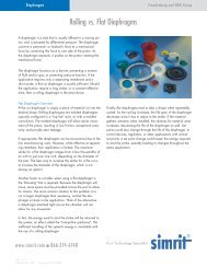
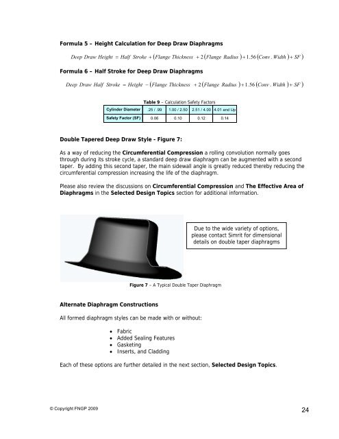
Formula 5 – Height Calculation for Deep Draw <strong>Diaphragm</strong>sDeep Draw HeightFlangeRadius 1.56 ConvWidth Half Stroke Flange Thickness 2.SF Formula 6 – Half Stroke for Deep Draw <strong>Diaphragm</strong>sDeep Draw HalfStrokeFlangeRadius 1.56 ConvWidth Height Flange Thickness 2.SF Cylinder DiameterSafety Factor (SF)Table 9 – Calculation Safety Factors.25 / .99 1.00 / 2.50 2.51 / 4.00 4.01 and Up0.06 0.10 0.12 0.14Double Tapered Deep Draw Style - Figure 7:As a way of reducing the Circumferential Compression a rolling convolution normally goesthrough during its stroke cycle, a standard deep draw diaphragm can be augmented with a secondtaper. By adding this second taper, the main sidewall angle is greatly reduced thereby reducing thecircumferential compression increasing the life of the diaphragm.Please also review the discussions on Circumferential Compression and The Effective Area of<strong>Diaphragm</strong>s in the Selected <strong>Design</strong> Topics section for additional information.Due to the wide variety of options,please contact <strong>Simrit</strong> for dimensionaldetails on double taper diaphragmsFigure 7 – A Typical Double Taper <strong>Diaphragm</strong>Alternate <strong>Diaphragm</strong> ConstructionsAll formed diaphragm styles can be made with or without: Fabric Added Sealing Features Gasketing Inserts, and CladdingEach of these options are further detailed in the next section, Selected <strong>Design</strong> Topics.© Copyright FNGP 200924