Diaphragm Design Manual - Simrit
Diaphragm Design Manual - Simrit
Diaphragm Design Manual - Simrit

You also want an ePaper? Increase the reach of your titles
YUMPU automatically turns print PDFs into web optimized ePapers that Google loves.
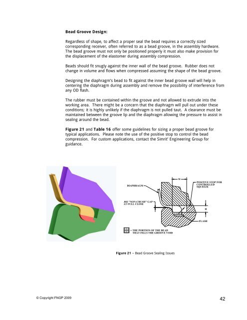
Bead Groove <strong>Design</strong>:Regardless of shape, to affect a proper seal the bead requires a correctly sizedcorresponding receiver, often referred to as a bead groove, in the assembly hardware.The bead groove must not only be positioned properly it must also make provision forthe displacement of the elastomer during assembly compression.Beads should fit snugly against the inner wall of the bead groove. Rubber does notchange in volume and flows when compressed assuming the shape of the bead groove.<strong>Design</strong>ing the diaphragm’s bead to fit against the inner bead groove wall will help incentering the diaphragm during assembly and remove the possibility of interference fromany OD flash.The rubber must be contained within the groove and not allowed to extrude into theworking area. There might be a concern that the diaphragm will pull out under theseconditions; it is highly unlikely if the diaphragm is not pulled taut. A clearance must bemaintained between the groove lip and the diaphragm allowing the pressure to assist insealing around the bead.Figure 21 and Table 16 offer some guidelines for sizing a proper bead groove fortypical applications. Please note the use of the positive stop to control the beadcompression. For custom applications, contact the <strong>Simrit</strong>’ Engineering Group forguidance.DIAPHRAGMWPOSITIVE STOP FORCONTROLLEDSQUEEZE.002 "NON-CRUSH" GAPAT FULL CLOSEHFLASH= THE PORTION OF THE BEADTHAT FILLS THE GROOVE VOIDFigure 21 – Bead Groove Sealing Issues© Copyright FNGP 200942