Maintenance Manual for Eleven Lab - Mits
Maintenance Manual for Eleven Lab - Mits
Maintenance Manual for Eleven Lab - Mits

You also want an ePaper? Increase the reach of your titles
YUMPU automatically turns print PDFs into web optimized ePapers that Google loves.
Version 1.1 – 9/30/2012<br />
<strong>Maintenance</strong> <strong>Manual</strong> <strong>for</strong> <strong>Eleven</strong> <strong>Lab</strong><br />
Lubricate<br />
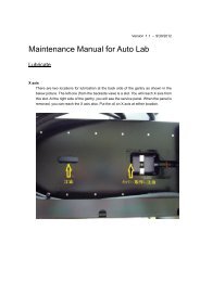
X axis:<br />
There are two locations <strong>for</strong> lubrication at the back side of the gantry as shown in the<br />
below picture. The left one (from the backside view) is a slot. You will reach X axis from<br />
this slot. At the right side of the gantry, you will see the service panel. When the panel is<br />
removed, you can reach the X axis also. Put the oil on X axis at either location.
Y axis:<br />
There are two ways <strong>for</strong> reaching Y axis.<br />
One is that you can lay the machine so that you will see the Y axis lead screw from the<br />
bottom side of the machine. Put the oil on Y axis lead screw.<br />
Another way is that you will put the oil from the slit of the left side or right side of the<br />
machine. Long stick is necessary to reach Y axis lead screw.
Z axis:<br />
You can reach Z axis lead screw from the slit at the left side or right side of the cover<br />
panel as shown in the below picture. It’s not easy to remove this panel.<br />
So put the oil on the cotton swab and then put the oil on the lead screw from either slit.<br />
The yellow arrow in the below picture indicates the lower position of the slit.<br />
It may be easier, however, that you move the milling head down to the lower position<br />
and then put the oil from the upper position of the slit.
Cleaning spindle motor and collet chuck<br />
Loosen the screw fixing the pressure foot ant then remove<br />
the pressure foot.<br />
Then set the tool change lever at the release position.<br />
(Open position) so that you can remove the tool.<br />
Insert the tool without ring instead of the tool with ring.<br />
We will use the special wrench which comes<br />
with the machine.<br />
The tool without ring makes it easier to work<br />
with the wrench and also it protects the collet<br />
from the irregular strength while working<br />
with the collet.<br />
Using the special wrenches, apply the triangular<br />
hole to the bottom of the collet chuck as shown in<br />
the right picture.<br />
Turn the wrench clockwise in a way of arrow as<br />
shown in the right picture.<br />
The collet chuck is going to be loosened.<br />
Once it is loosened, the collet chuck can be easily<br />
rotated with your fingers.<br />
Loosen the collet further. Finally you will remove<br />
the collet chuck from the spindle motor.
With small brush, clean the chips and particles<br />
from the inner surface of the collet chuck.<br />
Apply small amount of alcohol on the cotton swab.<br />
Wipe with it and remove the oil and grease<br />
from the inner and outer surface of the collet chuck.<br />
Make sure that no chips and particles are left behind<br />
in the slit of the collet chuck.<br />
Also, you need to clean the inner side of the spindle<br />
motor housing using brush and cotton swab with<br />
small amount of alcohol.<br />
! CAUTION!<br />
Never blow air at the spindle motor.<br />
Now you will see everything is clean.
Install the collet chuck:<br />
Insert the collet chuck into the spindle motor<br />
and then insert the tool without ring into the collet.<br />
Turn the collet counter clockwise by your finger.<br />
It’s going to be installed in the spindle motor.<br />
When it becomes tight <strong>for</strong> hand tightening,<br />
use the triangular hole of the special wrench<br />
to rotate further.<br />
Please keep the dummy tool inside the chuck<br />
during this work.<br />
You will feel it become heavier and you will see<br />
the section as shown with asterisk in the right<br />
picture starts rotating together with the collet<br />
chuck turning.<br />
From this point, turn the collet chuck together<br />
with the part of asterisk 180 degree more.<br />
Try to change the tool change lever position<br />
at open and close several times to make sure<br />
the tool change is done properly.
Install the pressure foot:<br />
Put the pressure foot back to the milling head.<br />
Then secure it with screw.<br />
Adjust the angle of the pressure foot properly.<br />
The picture at the right side shows the good example<br />
of the pressure foot location.<br />
Looking from the left side of the machine, the center<br />
line of pressure foot looks on the same line with<br />
the tool bit.<br />
This is the proper location of the pressure foot.<br />
The picture at the right side shows the bad example<br />
of the pressure foot location.<br />
The pressure foot is not aligned with the tool bit.