Seven Mini / Eleven T - Mits
Seven Mini / Eleven T - Mits
Seven Mini / Eleven T - Mits

You also want an ePaper? Increase the reach of your titles
YUMPU automatically turns print PDFs into web optimized ePapers that Google loves.
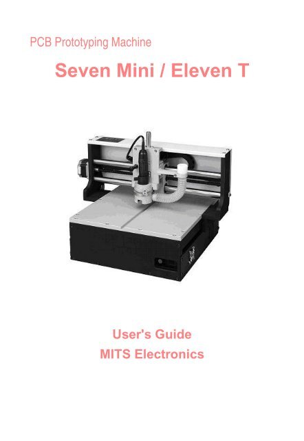
PCB Prototyping Machine<br />
<strong>Seven</strong> <strong>Mini</strong> / <strong>Eleven</strong> T<br />
User's Guide<br />
MITS Electronics
Revision<br />
Date Page Description<br />
091210 Long board Added<br />
091210 (whole)<br />
100507 Adjust<br />
Improve problem of requiring Acrobat Japanese<br />
font pack<br />
Home/Home2 buttons are renamed to SetP1P2/<br />
Re-Skew<br />
100720 Setup 64 bit USB driver is released
CONTENTS:<br />
Setup Guide<br />
●<br />
●<br />
●<br />
●<br />
●<br />
●<br />
●<br />
●<br />
●<br />
●<br />
●<br />
Notes of Caution<br />
Connect Boardmaker(7m11t)<br />
Install Software(mdp)<br />
Install USB Driver<br />
Registration(mdp)<br />
Start Up the System<br />
Change Application to CAM<br />
Port Settings<br />
Trouble Shooting-RS232C<br />
Trouble Shooting-USB<br />
USB Root Hub<br />
Basic Information<br />
●<br />
●<br />
●<br />
●<br />
●<br />
●<br />
●<br />
Name of Parts of <strong>Seven</strong> <strong>Mini</strong> (Front)<br />
Name of Parts of <strong>Eleven</strong>T (Front)<br />
Name of Parts (Rear)<br />
Tools<br />
Change the Tool(7m11t)<br />
Contact/Non-Contact Method<br />
Alignment of Top and Bottom<br />
Registration Pin and Underlay<br />
●<br />
●<br />
●<br />
●<br />
Registration Pin on Table<br />
Set P3<br />
Make Hole for Registration Pin<br />
Backup P3 Info
Working with standard FR-4<br />
●<br />
●<br />
●<br />
●<br />
●<br />
●<br />
●<br />
●<br />
●<br />
●<br />
●<br />
●<br />
●<br />
●<br />
●<br />
●<br />
●<br />
●<br />
●<br />
●<br />
●<br />
●<br />
Change Pressure Foot<br />
Preparing Tools for FR-4<br />
Set Adjust Method<br />
Display Milling Data<br />
Start Job (Top)<br />
Adjust<br />
Size of Board Material<br />
Set P1 point<br />
Adjust Depth of Cut<br />
Make Hole for Registration Pin(Board)<br />
Drill P1-P2<br />
Drill (Top)<br />
Milling (Top)<br />
ESC key to Interrupt<br />
Redo<br />
Mill Selectively<br />
Resume<br />
Turn Over Board<br />
Start Job (Btm)<br />
Milling (Btm)<br />
Start Job (Routing)<br />
Ensure Depth of Cut<br />
Working with Teflon Material<br />
●<br />
●<br />
●<br />
●<br />
●<br />
●<br />
Change Pressure Foot<br />
Preparing Tools<br />
Secure Thin Material<br />
Adjust Depth of Cut(RF)<br />
Milling Parameters<br />
Adjust Depth of Cut(Drill&Router)
Long Board<br />
●<br />
●<br />
●<br />
Divide Data<br />
Mill Lower Part<br />
Align Upper Part
Notes of Caution<br />
DO NOT get close to the board maker during milling.<br />
Be especially care ful around the area of the head.<br />
Be sure not to get your face injured or your hand caught in the mechanism.<br />
Also, please wear protective goggles or similar protective equipment while the<br />
board maker is operating.<br />
Attach the dummy tool not in use<br />
While the board maker is not used, attach the dummy tool bit to the chuck of the<br />
spindle motor.<br />
It is useful to expand the lifetime of the chuck of the spindle moter.<br />
Recovery from the hard limit error<br />
If the head passes outside the maximum milling range, the message "Hard limit<br />
detected" will appear on the screen.<br />
In such an event, you need to recover the board maker's home point.<br />
Click "To Initial" on the Manual Operation screen.<br />
Another way is to shut down the board maker and Flashwin and then restart<br />
both of them.<br />
SHIFT+ESC key to cancel waiting<br />
If you click the icon to start the communication to the board maker which is still<br />
turned off, the mouse pointer changed to the timer icon and keep waiting for the<br />
reply from the board maker.<br />
In this event, press SHIFT+ESC key to cancel waiting for the reply. Ctrl+Alt+Del<br />
is not necessary.
Connect Boardmaker to Your PC and Other<br />
Equipments<br />
<strong>Seven</strong> <strong>Mini</strong><br />
<strong>Eleven</strong>T<br />
<strong>Eleven</strong>THP
Install Software<br />
MITS Design Pro is a software for PCB design, converting data from other CAD system and<br />
controls the machine.<br />
PC Specfications:<br />
OS: Windows XP/Vista/7 (NOT supported WinXP 64bit)<br />
RS232C or USB port is required.<br />
Install Procedures:<br />
Open CD-ROM and then start Designpro_en_setup.exe to install the software.<br />
Choose the appropriate items in the list during the set-up procedure:<br />
*Common component must be installed together with the applications.<br />
It includes Converter and EASYCAD.<br />
Choose one of the following applications related to your board maker:<br />
*CAM-21RS controls FP-7A / FP-21A < including HP option>.<br />
*CAM-Circuit2 controls <strong>Seven</strong> mini / <strong>Eleven</strong>-T < including HP option>.<br />
*CAM-Lab controls <strong>Eleven</strong> Lab.<br />
*CAM-Auto controls Auto Lab.<br />
*CAM-T controls FP-21T < including HP option>.<br />
*CAM-TP controls FP-21T Precision.<br />
*CAM-Z controls <strong>Eleven</strong> Auto / FPZ-31AT / FPZ-73AT.<br />
Please check also Design View if the Fidicial Positioning Camera is equipped.
Install USB driver<br />
If your board maker has a USB port, it is possible to communicate with your PC via USB.<br />
Check "Install USB driver for milling machine now" at<br />
the final screen of Design pro setup.<br />
Device driver installation will begin..<br />
Follow the screen messages and installation will be<br />
completed.
Registration<br />
Registration is necessary to continue to use MITS Design Pro and board<br />
maker. The following screen is displayed when MITS Design Pro is started.<br />
Please enter the license code and then click OK to finish the registration.<br />
Otherwise, click "Trial use" to evaluate the software for 1 month.<br />
MITS Electronics submit 2 type of license code:<br />
- Activates optional EASYCAD<br />
- No optional EASYCAD (Converter+CAM ONLY)<br />
License Policy:<br />
One boardmaker includes one license of<br />
<strong>Mits</strong> Design Pro software.<br />
With this one license, you can install it<br />
to a PC for the control of the machine,<br />
and to another PC for making milling data<br />
for the machine.<br />
When you install to 2nd PC, enter same license code of<br />
1st PC.<br />
If you need more license, please purchase one license<br />
on one PC.
Start Up the System<br />
The Sequence of Starting Up the Equipments<br />
1. Turn on the computer (Windows).<br />
2. Start up the software.<br />
3. Turn on the Boardmaker.<br />
When turning on the boardmaker, the milling head automatically makes the homing action:<br />
It confirms the limit of each axis Z -> Y -> X and then stop at the initial position (home position).<br />
Do NOT turn on the boardmaker until the computer has been completely started up.<br />
Otherwise, communication may fail.<br />
Be sure the air supply if it is necessary for your boardmaker.<br />
At the first time of turning on the boardmaker via USB, the "Found New Hardware<br />
Wizard" will appear.<br />
Please refer to USB settings for installing USB driver.
Change Application to CAM<br />
Choose Application menu at the upper right corner of the screen:<br />
EasyCAD : Used for designing PC boards. (Option)<br />
Converter : Converts Gerber and DXF data.<br />
CAM xxx : You will find one CAM application in the list.<br />
Please check the correct CAM application which matches the model of the boardmaker is installed.<br />
If not, it is necessary to re-install the software.<br />
CAM<br />
CAM-21RS<br />
CAM-Circuit2<br />
CAM-Lab<br />
CAM-T<br />
CAM-TP<br />
CAM-Z<br />
CAM-Auto<br />
Model<br />
FP-7A, FP-21A<br />
<strong>Seven</strong> <strong>Mini</strong>, <strong>Eleven</strong> T<br />
<strong>Eleven</strong> Lab<br />
FP-21T<br />
FP-21T Precision<br />
<strong>Eleven</strong> Auto, FPZ-31AT, FPZ-73AT<br />
Auto Lab<br />
Please click CAM in the list and it will be changed to the CAM application.<br />
Before working with the boardmaker, it is necessary to prepare the milling data using<br />
EasyCAD or Converter.<br />
Please refer to the EasyCAD/Converter manual for the detail operations.
Port Settings<br />
Choose CAM Prefs. menu -> Board Maker on CAM screen.<br />
RS232C Cable between Boardmaker and PC<br />
●<br />
Set RS232C port to the available COM port such as "COM1".<br />
USB Cable between Boardmaker and PC<br />
●<br />
●<br />
Set RS232C port to "USB".<br />
It is not necessary to set Baudrate.<br />
Restart the software when the port settings are changed.<br />
This setting is available from the next start.
Trouble Shooting - RS232C<br />
1. No response (mouse pointer keeps hourglass)<br />
Press Shift+ESC to cancel the communication at once.<br />
And then check the following items:<br />
❍ Power is not turned on yet.<br />
❍ RS232C cable is not connected.<br />
❍ RS232C cable is wrong (Straight/Reverse)<br />
Refer also to "Connect Boardmaker" in User's guide.<br />
2. Message "Port Open Error" "Port No. Error"<br />
❍ Port No. is wrong.<br />
Choose CAM Prefs. -> boardmaker.<br />
And re-confirm that RS-232C field is correct port No.(COMx)<br />
❍ Re-start the software when RS-232C field is changed.<br />
The settings will be available from the next start.
Trouble Shooting - USB<br />
1. Message "Port Open Error"<br />
❍ Power is not turned on yet.<br />
❍ USB driver is not installed yet.<br />
❍ USB cable is not connected.<br />
In this case, there is no MITS USB driver in device manager screen.<br />
2. There is MITS USB driver in device maneger screen.<br />
However, no response when Start Job icon is clicked.<br />
❍ Press Shift+ESC to cancel the communication at once.<br />
And then try again.<br />
❍ If no response without message, choose CAM Prefs -> boardmaker.<br />
And re-confirm that RS-232C field is set to USB.<br />
And re-start the software.<br />
3. No response when Start Job icon is clicked.<br />
And Shift+ESC key cannot cancel the communication.<br />
❍ Turn off the boardmaker and then try Shift+ESC key to cancel.<br />
❍ If this situation frequently happens, change the properties of<br />
USB root hub in device manager screen (See another page)<br />
If everything mentioned above cannot solve the problem,<br />
or the communication is unstable,<br />
we have no choice but we recommend to use RS-232C communication.<br />
If your PC has no RS-232c port, try USB-Serial conversion cable<br />
which is sold in PC shop.
Setting of USB Root Hub<br />
Open the device manager screen in control panel on Windows.<br />
Right click on USB Root Hub and click Properties.<br />
Click Power Management tab,<br />
Check off the Allow the computer to turn off...<br />
There are several USB Root Hub in screen.<br />
Do the same settings on all the USB Root Hub.<br />
Restart your computer when the settings are finished.
Basic Information
Name of Parts of <strong>Seven</strong> <strong>Mini</strong> (Front)<br />
1. Power Switch<br />
2. Head<br />
3. Spindle Motor<br />
4. Head Holding Knob<br />
5. Tool Change Knob<br />
6. Depth Adjustment Screw<br />
7. Pressure Foot<br />
8. Head Lowering Speed Adjustment Volume
Name of Parts of <strong>Eleven</strong> T (Front)<br />
1. Power Switch<br />
2. Head<br />
3. Spindle Motor<br />
4. Head Holding Knob<br />
5. Tool Change Knob<br />
6. Depth Adjustment Screw<br />
7. Pressure Foot<br />
8. Head Lowering Speed Adjustment Volume
Name of Parts (Rear)<br />
<strong>Seven</strong> <strong>Mini</strong><br />
<strong>Eleven</strong> T<br />
REAR VIEW<br />
1. Vacuum Hose<br />
2. RS232C Port<br />
3. USB Port<br />
4. Outlet for Vacuum Cleaner<br />
5. Power Plug<br />
6. Fuse (2A)
Tools<br />
Tool Size Application<br />
Milling bit<br />
90 degree<br />
60 degree<br />
(The tip is<br />
pointed-end)<br />
For standard FR-4 material such as 1.6mm<br />
(0.063") thickness.<br />
●<br />
●<br />
For milling outlines and rubout<br />
36mm (1.42") overall length<br />
Endmill 1.0mm (0.40")<br />
and more..<br />
For standard FR-4 material such as 1.6mm<br />
(0.063") thickness.<br />
●<br />
●<br />
For removing copper with large width.<br />
36mm (1.42") overall length<br />
RF Milling 0.2mm (0.008")<br />
0.3mm (0.012")<br />
0.5mm (0.020")<br />
and more..<br />
For Teflon(PTFE) and/or thin material<br />
●<br />
●<br />
●<br />
For milling outlines and rubout.<br />
38.1mm (1.5") overall length.<br />
Recommended to use with the<br />
machine equipped with non-contact<br />
pressure foot.<br />
Drill various ● For drilling holes.<br />
● 38.1mm (1.5") overall length.<br />
Router<br />
(Forming cutter)<br />
0.8mm (0.31")<br />
1.0mm (0.39")<br />
2.0mm (0.78")<br />
and more..<br />
●<br />
●<br />
For routing inner and outer board<br />
contours.<br />
38.1mm (1.5") overall length.
Change Tool<br />
Raise the head to the hold position.<br />
Pull and turn the holding knob slightly to match the slit.<br />
It goes into the slit and the head will be hold at that postion.<br />
To release the tool bit,<br />
Turn the tool change knob of the spindle motor to the right side.<br />
The tool bit will be released.<br />
Use the tweezer to hold the tool bit not to drop it in <strong>Eleven</strong> T.<br />
In <strong>Seven</strong> mini, hold the tool bit by hand.<br />
To install the tool bit,<br />
Insert the bit into the collet chuck.<br />
Please make sure that the bit is inserted to the inside bottom of the chuck.<br />
Turn the tool change knob to the left side.<br />
The bit will be secured.<br />
And then release the holding knob of the head assembly.<br />
Hold down the head slowly to the original position.<br />
When the head is released, please support the head by your hand not to fall it.<br />
Otherwise, the tool bit may be broken when the head falls down.<br />
While the board maker is not used, attach the dummy tool bit to the chuck of the<br />
spindle motor. It is useful to expand the lifetime of the chuck of the spindle moter.<br />
The head holding knob should be locked at the position which the slits don't match<br />
each other except the tool change. Otherwise, it may prevent from the smooth up and<br />
down motion of the head.
Contact & Non-Contact Method<br />
When making boards with fine patterns, we usually adopt the incremental<br />
milling method in which the material board is held down and the tool tip<br />
is made to stick out accurately from the very point where the board is<br />
being held down. For holding down the material boards,<br />
there are two methods called the contact method and the non-contact method.<br />
Contact Method<br />
This system leaves the thin trace of pivot touch on the surface of copper foil.<br />
(But this pivot does not leave any scratch.)<br />
You don't have an air compressor using contact method.<br />
Non-Contact Method (HP option)<br />
As the jet of air pushes down the board without touching, this system leaves<br />
no trace on the copper foil.<br />
Therefore, this system is suitable for the processing of thin or soft materials.<br />
However, additionally you have to have an air compressor.
Alignment for Making the Double-Sided Board<br />
There are two approach of alignment for making the double-sided board.<br />
Registration Pin (reference pin, alignment pin)<br />
Make two holes for pins on the machine table and PC board.<br />
The board is turned over by the help of these pins.<br />
Fiducial positioning camera<br />
Make two holes on PC board.<br />
These holes are called P1 and P2<br />
which are on the corner of the milling data.<br />
When the board is turned over without pins,<br />
the board is placed angled.<br />
See the P1 and P2 holes with camera<br />
and the software caliculate the angle of the board.<br />
(This operation is not automated.)<br />
Mostly, the registration pins are not necessary when using<br />
camera.<br />
Please note, However, that the right side of the working area is out of range that the camera can<br />
see due to the mounting position of the camera.<br />
So milling large board needs the registration pin although you have the camera system.
Registration Pin and Underlay
The Concept of the Registration Pin on Table<br />
The couple of pins should be located vertically (along<br />
Y axis ) on the center<br />
of the table. The front pin is called "P3". Another pin<br />
on the back side has<br />
no name especially.<br />
Considering the working area size of the machine and<br />
the board material size<br />
which you often use, there is a recommended<br />
distance between two pins.<br />
In LAB series such as <strong>Eleven</strong> Lab and Auto Lab, the whole table is the plastic plate and the<br />
recommended pin distance is as follows:<br />
Board Material Size<br />
Recommended Pin<br />
Distance<br />
200x250mm<br />
(8"x10")<br />
240mm<br />
(9.5")<br />
In some of MITS machines, there is a couple of the<br />
plastic plate to be put into the aisle of the table.:<br />
<strong>Seven</strong> <strong>Mini</strong>, <strong>Eleven</strong> T, FP-21T, FP-21T<br />
Precision, <strong>Eleven</strong> Auto, FPZ-31AT<br />
Board<br />
Material Size<br />
Recommended Pin<br />
Distance<br />
250x200mm<br />
(10"x8")<br />
190mm<br />
(7.5")<br />
The values introduced in this section are one of the recommendations and there may be the<br />
other suitable distance of the pins depending on the situations.
Set P3 for <strong>Seven</strong> <strong>Mini</strong> and <strong>Eleven</strong>T<br />
Click Manual Operation icon so that the head comes to the front location and the<br />
manual operation screen appears.<br />
Change the tool to 38.1mm (1.5") length bit.<br />
Turn the depth adjustment screw shallwer so that<br />
the bit touches just the surface of the board.<br />
This depth setting is helpful when the hole of<br />
registration pin is made later.<br />
Move the head to the desired P3<br />
location using the manual operation<br />
screen.<br />
You may press down the head by hand.<br />
It is easy to see the location when the<br />
head is down.<br />
Click Set P3 temporarily to register the P3 location to the software.<br />
Attempt to move the head backwards with the recommended pin distance.<br />
If you don't encounter any limit error, it is good.<br />
It means the couple of pins are inside the working area.<br />
If P3 location is necessary to re-adjust, move the head to the desired location<br />
and then click Set P3 again.<br />
If you encounter the hard limit error (L), click To Initial on the manual operation<br />
screen. It will retreive the current location of the head. Otherwise, the software will lost<br />
the position.<br />
If you don't see Set P3 button in manual operation screen. Close screen and choose<br />
CAM Prefs.-> Boardmaker screen. Set Reference to P1-P2 Revised. And<br />
then, try again.
Make Hole for Registration Pin<br />
The dimension is :<br />
However, this dimension is not so necessary to be precise.<br />
- The thickness of the plate is 6 mm.<br />
- The length of the registration pin is 8 mm.<br />
- 3 - 4 mm of the pin is sticked out of the plate.<br />
Secure underlay on the table with tape.<br />
Change the tool to the special drill bit<br />
for making a hole for the pin.<br />
When the depth screw is adjusted good,<br />
the special drill bit is 6 - 7mm out of<br />
the pressure foot.<br />
Set Lower2 to 3mm/sec.<br />
Move the head to the P3 point, click spindle ON and then click Down to<br />
lower the head,<br />
so that the head will make the hole for the registration pin.<br />
Click Up to raise the head, move 190 mm backwards and drill the hole too.<br />
After work, set Lower2 to the previous value.
Backup P3 Info<br />
After making hole for the registration pin,<br />
it is recommended to make backup of P3 coodinate.<br />
Close Manual Operation Screen.<br />
Choose CAM Prefs. -> Save P3.<br />
Enter the file name and then click save<br />
And P3 coodinates are stored to the file.<br />
If the coodinate is lost accidentally,<br />
you can retreive P3 coodinates by load P3 in CAM Prefs. menu.
Working with Standard FR-4
Change Pressure Foot Non-Contact -> Contact<br />
The contact-pressure foot is suitable for milling the standard FR-4 material.<br />
You don't have an air compressor using the contact method.<br />
If you have two type of pressure foots: contact and non-contact.<br />
The following procedures are changing the pressure foot to contact.<br />
Please remove the tool bit before changing the pressure foot.<br />
Close the valve of air regulater on the back of the<br />
machine.<br />
Pull out air hose from the non-contact pressure<br />
foot.<br />
Push down the tip of the hose joint and then pull<br />
out the hose.<br />
Also, remove the vacuum hose on the right side<br />
of the pressure foot.<br />
Loosen the screw of pressure foot.:<br />
(1) on front side<br />
(2) on right side<br />
Raise the head a little and then remove the non-contact pressure foot.<br />
And then attach the contact pressure foot and tighten the screw.
Prepare Tools for working with standard FR-4<br />
Prepare the following tool bits for working with FR-4 material.<br />
1. Milling (Pointed-end):<br />
Pointed 90 degree is most frequently used for standard milling.<br />
90 degree milling bit is suitable for milling width 0.2mm-0.4mm<br />
60 degree milling bit is suitable for milling width 0.1mm-0.2mm<br />
Endmill is suitable for rubout (removing copper).<br />
2. Drill and Router (Forming cutter):<br />
Check the diameters used in your pcb data and prepare them.<br />
Choose Information -> Tool List.<br />
It will help you to check the diameters used in pcb data.
Set Adjust Method<br />
Open the Board Maker screen from CAM Prefs menu.<br />
Set Reference to P1-P2 Revised.<br />
P1-P2 Revised is one of the adjust (alignment) methods and the further operations will<br />
be explained later.
Display Milling Data<br />
Choose Open from the File menu and select the file name from the list.<br />
Then click Open to display the data on screen.<br />
For this example, open Mdemo.<br />
Before the milling operation with the boardmaker, it is necessary to prepare the milling<br />
data using EasyCAD or Converter.<br />
Please refer another manual for how to use EasyCAD and Converter.
Start Job<br />
Click the Start Job icon.<br />
For this example, select:<br />
Click OK.<br />
1. Drill (Top)<br />
2. Milling outlines (Top)
Click Adjust to Call Up the Manual Operation<br />
Screen<br />
When OK is clicked in the Milling<br />
Sequence Settings screen, the<br />
Board Top/Bottom Change screen<br />
appears.<br />
Click Adjust to call up the Manual Operation screen.<br />
You can move the head to left, right, front<br />
and back using move buttons in the<br />
manual operation screen.
Size of Board Material<br />
It is necessary to prepare the board material which has enough size to mill.<br />
It is easier to understand what is enough size to put the board material temporarily<br />
on the table and move the head of the machine from P1 to P2.<br />
●<br />
Range where Pressure Foot Moves:<br />
Though it depends on the model of Pressure Foot,<br />
it requires the 15 - 50mm margin for pressure foot.<br />
●<br />
Margin for Securing Tape:<br />
It requires approx. 5mm margin for securing tape.<br />
●<br />
Space for Stuck Pins:<br />
It requires 3 mm holes for stuck pin to the underlay and the board material.<br />
The stuck pins should stand outside the range where the pressure foot moves.<br />
Put board on table and secure it with tape.
Set P1 Point and then Confirm P2 Location<br />
Adjust<br />
First, we need to set the milling reference point (P1).<br />
● Click on the move buttons (FRONT, BACK, etc.) to move the head to any location on the<br />
board.<br />
● Click on the Set P1-P2 button, and that location will become P1.<br />
● At this time, a < Align P2? > message will appear, but just click No.<br />
● When P1 has been set, please check the location of P2:<br />
Click the P2 button and the head will move to P2.<br />
Please confirm that the milling area fits within the board.<br />
If you want to change P1, move the head again to the desired location and click Set P1-<br />
P2.<br />
It is very important to check the location of P2.<br />
If the head goes outside of the board during milling, it may cause accident<br />
such as breaking the bit, hurt the surface of the table and so on.
Adjust Depth of Cut<br />
Make a test cut to check the width of the channel cut by the milling cutter.<br />
Change the tool to milling bit.<br />
First, turn the adjustment screw enough<br />
shallower so that the milling bit doesn't<br />
touch the surface of the board.<br />
From now, we will make a trial cut.<br />
So move the head to the outside of P1-P2 milling area to prevent from hurting the surface inside<br />
the P1-P2 area. (use the FRONT, BACK, LEFT, RIGHT move buttons as needed)<br />
Turn ON the spindle motor.<br />
Click DOWN to lower the head.<br />
Turn the depth adjustment screw deeper<br />
so that the bit gets into the board surface.<br />
In this position, press one of the move buttons once and a trial cut will be made.<br />
Click UP to raise the head.<br />
Turn OFF the spindle motor.<br />
Move the head aside so that you can check the result of cut.<br />
Check the width of the channel that was cut.<br />
Adjust the milling cutter depth and make trial cut several times<br />
so that the width of this channel is the same as the diameter of the tool<br />
specified in EASYCAD or the Converter program for milling outlines.
Make Hole for Registration Pin on Board<br />
When processing double-sided board, the hole for registration pin<br />
is necessary on board.<br />
Change the tool to 3mm drill.<br />
When the depth screw is adjusted good with the milling bit which is<br />
2mm shorter than the drill bit, the 3mm drill bit is 2mm out of<br />
the pressure foot.<br />
Click P3 to move the head on p3 point.<br />
Move the head to the P3 point, click spindle ON and then click Down to lower the head,<br />
so that the head will make the hole for the registration pin.<br />
Click Up to raise the head, move 190 mm backwards and drill the hole too.<br />
Insert the registration pin into the hole.<br />
Otherwise, you may insert registration pin when milling top side was<br />
finished and you need the alignment for bottom side.
Drill P1 and P2 Location<br />
After setting the reference point, we need to make the reference holes for P1 and P2.<br />
Reference holes are used for the alignment using optional camera system.<br />
Also, making these holes are useful for understanding how large the milling area is.<br />
● Attach the drill.<br />
For example, 0.8mm drill.<br />
● Click on Drill P1-P2 and the head will move the P2 point.<br />
And then a message "Ready to drill P1 and P2?" will appear.<br />
● Click Yes on the message screen and the head will start to drill holes on P2 and P1.<br />
● After the reference points has been drilled, click OK on the manual operation screen.<br />
And the manual operation screen will close and go back to the Board Top/Bottom<br />
Change screen.
Drill (Top)<br />
Click Continue to proceed the next<br />
Tool Change screen.<br />
●<br />
●<br />
●<br />
This screen will appear when your<br />
board maker need the tool change<br />
manually.<br />
The layer to be milled and the tool<br />
number and tool diameter in the milling<br />
data are displayed here.<br />
Change the tool to the one displayed in<br />
this screen.<br />
Click Continue to start drilling.<br />
DO NOT touch the spindle motor or allow your face to get near it during milling.<br />
To interrupt the milling operation, press ESC key. After finishing the milling data which<br />
has been already sent, the operation will stop.<br />
If emergency stop is needed, turn off the power switch.
Milling Outlines (Top)<br />
When the drilling process is<br />
finished, the Board Top/Bottom<br />
Change screen will appear<br />
again to tell that you will enter<br />
the milling process.<br />
Click Continue to proceed the<br />
next Tool Change screen.<br />
●<br />
●<br />
The layer to be milled and the tool<br />
number and tool diameter in the milling<br />
data are displayed here.<br />
Change the tool to the one displayed in<br />
this screen.<br />
Click Continue to start milling.
ESC Key to Interrupt<br />
To interrupt the milling operation, press ESC key.<br />
After finishing to process all the milling data which has been already sent,<br />
(which was shown by red color in the screen)<br />
the operation will stop.<br />
If emergency stop is needed, turn off the power switch.<br />
Using <strong>Eleven</strong> Auto, press emergency switch.
Redo<br />
In the event that a drill or milling cutter breaks during milling or you find there is still apart of the<br />
board that has not been milled, the software offers you 3 methods to mill just the part of the board<br />
that still needs it.:<br />
Redo, Mill selectively and Resume<br />
Redo<br />
When Redo is clicked, the Redo screen appears and asks you to enter which board in the<br />
sequence you want to redo milling from. The number to the right of the entry field indicates the<br />
total number of boards in the sequence.<br />
When the message appears, click on the element from which milling is to be redone (started<br />
again). The data that will be milled is displayed in the red and yellow.<br />
If step milling is checked, software ask<br />
which step you want to start from.<br />
Redo from 0 or 1 means redo from 1st<br />
step.<br />
When the element to be redone is confirmed, the Tool Change screen will appear.<br />
Click Continue to start milling.
Mill Selectively<br />
Click Mill selectively icon.<br />
The most of operations are very similar to the<br />
usual one.<br />
The difference is that it needs an operation to<br />
select area to be milled.<br />
This operation is done after Continue is clicked in<br />
the Board Top/Bottom Change screen.<br />
Click on an element or drag rectangle so that<br />
element(s) change its color. It is "selected".<br />
After selection, right-click -> Confirm<br />
to go to the next step.<br />
The rest of operations is same as the usual one.<br />
The software will mill only the selected area.
Resume<br />
When suspend button is clicked<br />
to terminate job.....<br />
You can resume job by Resume icon.<br />
Resume information is available until you leave CAM application<br />
or another file is opened
Turn Over Board<br />
Turn over the board as illustrated below.<br />
From TOP view, P1 is located on the front-left.<br />
From BOTTOM view, P1 is located on the front-right.
Start Job (Bottom Side)<br />
Click Start Job icon.<br />
For this example, select:<br />
Click OK.<br />
1. Milling outlines (Btm)<br />
When OK is clicked in the Milling Sequence<br />
Settings screen, the Board Top/Bottom<br />
Change screen appears.
Milling Outlines (Bottom)<br />
The following<br />
operations are<br />
same as milling top<br />
side.<br />
Click Continue to<br />
proceed the next<br />
Tool Change<br />
screen.<br />
●<br />
●<br />
●<br />
This screen will appear when your<br />
board maker need the tool change<br />
manually.<br />
The layer to be milled and the tool<br />
number and tool diameter in the milling<br />
data are displayed here.<br />
Change the tool to the one displayed in<br />
this screen.<br />
Click Continue to start milling.
Start Job (Routing)<br />
Click Start Job icon.<br />
And then select Routing (Btm) in the Milling Sequence Settings screen.<br />
Click OK.<br />
When Board Top / Bottom Change screen appears,<br />
click OK.<br />
When the Tool Change screen appears, attach the router bit (forming cutter).<br />
Before starting the milling operation, Be absolutely sure to check the milling speed.<br />
If this speed is too high, it could cause the tool to break.<br />
Click Continue to start the routing job after confirming the settings.<br />
The Sequence of the routing:<br />
When the drawings have the inside routing<br />
data, it is good to separate the tool No.<br />
for inside and outside.<br />
And also, tool No. for Inside should be<br />
smaller than one for outside<br />
because contour routing will process<br />
smaller tool No. first.<br />
Please refer Converter and EasyCAD manual for how to generate routing data.
Ensure Depth of Cut (Routing)<br />
If you want to ensure the depth of cut of routing bit,<br />
the following procedure is helpful to make sure the depth.<br />
Setting the Routing (Forming Cutter) Depth<br />
Follow the procudure below to adjust the depth of the routing bit:<br />
●<br />
●<br />
Click Manual to call up the Manual Operation screen.<br />
Use the Move buttons to move the head to the location shown in the illustration.<br />
●<br />
●<br />
●<br />
●<br />
●<br />
First, turn the adjustment screw enough shallower.<br />
Turn ON the spindle motor and click the Down button.<br />
Turn the depth adjustment screw little by little so that the depth of the routing bit<br />
gradually increases.<br />
When the bit reaches a depth where the tip of the bit will just slightly scratch the surface<br />
of the underplate, click the Up button and turn the spindle motor OFF.<br />
From that point, turn the adjustment screw shallower by 15-20 notches.<br />
Once this adjustment is complete, a two-sided board can be milled at a depth<br />
so that just enough of the copper plating will remain.
Working with Tefron(PTFE) and/or Thin material
Change Pressure Foot Contact -> Non-Contact<br />
If you have two type of pressure foot: contact and non-contact.<br />
The following procedures are changing the pressure foot to Non-contact.<br />
Please remove the tool bit before changing the pressure foot.<br />
Remove the vacuum hose on the right side of the pressure foot.<br />
Loosen the screw of the contact pressure foot.:<br />
(1) on front side<br />
(2) on right side<br />
Raise the head a little and then remove the contact pressure foot.<br />
Attach the non-contact pressure foot and tighten<br />
the screw.<br />
Also, attach the vacuum hose to the right side of<br />
the foot.<br />
Insert the air hose to the joint.<br />
Open the valve of air regulater on the back of the<br />
machine.<br />
The value is 0.4 - 0.45 MPa.
Prepaing Tools for working with Thin material<br />
Prepare the following tool bits.<br />
1. RF Milling (stub-end):<br />
2. Drill and Router (Forming cutter):<br />
Check the diameters used in your pcb data and prepare them.<br />
Choose Information -> Tool List.<br />
It will help you to check the diameters used in pcb data.
How to Secure Thin Material<br />
There is some difficulty to secure thin substrate on the machine table.<br />
Even though 4 sides of substrate are secured with tape,<br />
the center of substrate could not be secured and float.<br />
Adhesive Spray<br />
One of the ideas to secure thin substrate on table<br />
is to blow the adhesive splay on the bottom of substrate.<br />
Put the material on the underlay of the table.<br />
Wipe the surface of the material to make the surface smooth.<br />
Vacuum Table<br />
It is suitable to use vacuum table option<br />
for securing the thin substrate.<br />
It holds the substrate firmly on the machine table<br />
using the vacuum pressure.
Adjust Depth of Cut (RF Milling)<br />
The shape of RF milling bit is stub-end.<br />
This paper introduces how to get the depth of cut using RF milling bit.<br />
First, turn the adjustment screw enough shallow<br />
for bit<br />
not to touch the surface of the board.<br />
Lower the head and then turn the adjustment<br />
screw deeper<br />
until the bit touch the surface slightly.<br />
From the very suface point, turn the adjustment<br />
screw deeper,<br />
considering 1 click of screw is approximatly 3 um<br />
deep.<br />
It is very difficult to set the depth to mill ONLY<br />
copper foil<br />
without touching the substrate under copper foil.<br />
Set the depth under the copper foil to 20um at<br />
least.<br />
And set deeper if the milling result is still shallow.
Milling Parameters for Thin Material<br />
Click Manual before clicking Continue in Tool Change screen,<br />
set the milling parameters for RF milling bit in Manual Operation screen.<br />
Refer the following chart:<br />
RF Milling<br />
(mm)<br />
Spindle<br />
(x1000rpm)<br />
Milling spd.<br />
(FR4)<br />
(mm/sec)<br />
Milling spd.<br />
(Teflon)<br />
(mm/sec)<br />
Lower2<br />
(mm/<br />
sec)<br />
0.2 30 4-6 3-5 1-2<br />
0.3 30 8-10 6-8 1-2<br />
0.5 30 10-12 8-10 2-6
Adjust Depth of Cut (Drill&Router on Thin<br />
Material)<br />
The length of drill and router bit is same as RF milling bit.<br />
So it needs to make the depth of cut deeper in order to penetrate material.<br />
First, Remember the position of the depth adjustment screw<br />
where the depth of cut of RF milling is good.<br />
It is the reference point.<br />
Turn the adjustment screw deeper from<br />
this point with Board Thickness +0.5mm.<br />
It helps to know that turning<br />
the adjustment screw one round<br />
deeper direction become the depth<br />
of cut 0.5mm deeper.<br />
And 1 click of screw is approximately 3um deeper.
Long Board
Divide Long Board Data<br />
How to divide the longer board than the working area:<br />
For the preparation before dividing the long board data,<br />
use Make holes command and place 2 holes for alignment on data.<br />
The pair of holes must be placed horizontally.<br />
1. Click Make Holes button.<br />
2. Choose hole diameter from list box.<br />
3. Place 2 holes horizontally.<br />
File -> Save<br />
Save this data as the original one.<br />
4. Click Delete Inside/Outside Region button.<br />
5. Use mouse to make region surround the<br />
upper part beyond the alignment holes and<br />
delete it.<br />
Be careful not to delete the alignment holes.<br />
File -> Save As<br />
Save this data as different name.<br />
6. Open the original data again.<br />
Delete the lower part of the data<br />
with the same operation.<br />
7. Work Prefs -> Home.<br />
Place CAD Home point upon the left<br />
alignment hole<br />
Changing the location of CAD Home point is necessary for the alignment of the upper<br />
part to the lower part.
File -> Save As<br />
Save this data as another different name.
Milling Lower Part of board<br />
Open the lower part of board data.<br />
Go to CAM screen and milling this data as usual<br />
operation.<br />
After finishing the job, slide the pc board to<br />
the front and secure it.<br />
Take care that the alignment holes are<br />
inside the work area of the machine.
Align Upper Part of board<br />
In order to align the upper part to the lower part, it needs to change the alignment method to CAD<br />
HOME.<br />
CAM Prefs. -> Board maker screen in CAM, change Reference hole to CAD Home.<br />
Open the upper part of board data.<br />
Be sure that the location of CAD Home point is upon<br />
the left alignment hole.<br />
Start Design View to see the camera display.<br />
Click Start Job icon.<br />
In Manual screen which you always set P1 and P2,<br />
(Click Adjust button in Top/Bottom Change screen)<br />
you will notice Set P1-P2 button at the right side of<br />
manual screen disppear and CAD HOME button appear.<br />
Push Camera button at the upper left corner of the manual<br />
screen. It goes into Camera mode.<br />
Move camera to the location of the left alignment hole,<br />
and then click CAD HOME.<br />
When software ask you Align Angle ?,<br />
click Yes.<br />
Click CAD HOME button on the same location again to register the left hole as the first point of<br />
angle.<br />
Move camera to the location of the right alignment hole,<br />
now click CAD HOME button again. (third time)
Software caliculate angle of the board.<br />
Close the manual screen and you can mill<br />
the board as usual operation.<br />
When you turn over the board for milling<br />
bottom,<br />
the alignment can be made using CAD<br />
HOME button.