You also want an ePaper? Increase the reach of your titles
YUMPU automatically turns print PDFs into web optimized ePapers that Google loves.
Revision<br />
091208 Bug Fixed: require Acrobat Japanese font pack
Contents<br />
Basic Information<br />
● Installation<br />
● Registration<br />
● Starting Up<br />
● Exiting<br />
● Changing Applications<br />
● Screen<br />
● Change Unit (mm/inch)<br />
● Mouse Operation<br />
● Enter Coordinate<br />
● Layers<br />
● Aperture and Tool Settings<br />
● Select Elements<br />
Importing Gerber File<br />
● Gerber IN<br />
● Drill IN<br />
● Aperture and Tool Settings<br />
● Load Aperture<br />
● Trouble Shooting<br />
● Move Holes<br />
● Delete<br />
● Move Boardoutline<br />
● Draw Boardoutline<br />
Importing DXF File<br />
● DXF IN<br />
● Delete<br />
● Move Boardoutline<br />
● Draw Boardoutline<br />
● Draw Line
● Polygon Fill<br />
● Multiple Polygon Fill<br />
Importing Examples<br />
● Altium <strong>Design</strong>er (<strong>Pro</strong>tel) RS274X<br />
● Cadence OrCAD PCB Editor RS274X<br />
● Cadence OrCAD PCB Layout RS274X<br />
● Cadsoft EAGLE RS274X<br />
● CSi WinPCB RS274X<br />
● <strong>Design</strong>soft TINA RS274X<br />
● Mentor Graphics PADS RS274X<br />
Drawing with EASYCAD<br />
● Grid settings<br />
● Draw Boardoutline<br />
● Pad<br />
● Line&Pad<br />
● Print<br />
● Polygon Fill<br />
● Multiple Polygon Fill<br />
● SavePart<br />
● PlacePart<br />
● Change Attribute<br />
● Move Layer from Top to Bottom<br />
● Enlarge<br />
● Fonts<br />
● Text<br />
● Text to milling
Generating Milling data<br />
● Measure Distance<br />
● Auto Drill<br />
● Generate Outline<br />
● Generate Outline (Negative)<br />
● Generate Rubout<br />
● Generate Routing<br />
● Milling Through Gap
Basic Information
Install Software<br />
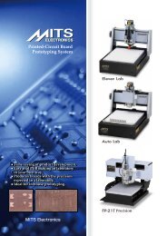
<strong>MITS</strong> <strong>Design</strong> <strong>Pro</strong> is a software for PCB design, converting data from other CAD<br />
system and controls the machine.<br />
PC Specfications:<br />
OS: Windows 2000(SP4 and newer edition)/XP Home(SP2)/XP <strong>Pro</strong>(SP2)/<br />
Vista<br />
NOT supported in 64bit operating system.<br />
RS232C or USB port is required.<br />
Install <strong>Pro</strong>cedures:<br />
Open CD-ROM and then start <strong>Design</strong>pro_en_setup.exe to install the<br />
program.<br />
Choose the appropriate items in the list during the set-up procedure:<br />
*Common component must be installed together with the applications.<br />
It includes Converter and EASYCAD.<br />
Choose one of the following applications related to your board maker:<br />
*CAM-21RS controls FP-7A / FP-21A < including HP option>.<br />
*CAM-Circuit2 controls Seven mini / Eleven-T < including HP option>.<br />
*CAM-TP controls FP-21T Precision.<br />
*CAM-T controls FP-21T < including HP option>.<br />
*CAM-Z controls Eleven Auto / FPZ-31AT / FPZ-73AT.
Registration<br />
Registration is necessary to continue to use <strong>MITS</strong> <strong>Design</strong> <strong>Pro</strong> and board<br />
maker. The following screen is displayed when <strong>MITS</strong> <strong>Design</strong> <strong>Pro</strong> is started.<br />
Please enter the license code and then click OK to finish the registration.<br />
Otherwise, click "Trial use" to evaluate the software for 1 month.<br />
<strong>MITS</strong> Electronics submit 2 type of license code:<br />
- Activates optional EASYCAD<br />
- No optional EASYCAD (Converter+CAM ONLY)<br />
License Policy:<br />
One boardmaker includes one license of<br />
Mits <strong>Design</strong> <strong>Pro</strong> software.<br />
With this one license, you can install it<br />
to a PC for the control of the machine,<br />
and to another PC for making milling data<br />
for the machine.<br />
When you install to 2nd PC, enter same license<br />
code of 1st PC.<br />
If you need more license, please purchase one<br />
license on one PC.
Start Up the Software<br />
To start up <strong>MITS</strong> <strong>Design</strong> <strong>Pro</strong>:<br />
[Start] -> [<strong>Pro</strong>gram] -> [Mits <strong>Design</strong> <strong>Pro</strong>] -> [<strong>Design</strong> <strong>Pro</strong>]<br />
To start up Correct DXF (Optional):<br />
[Start] -> [<strong>Pro</strong>gram] -> [Mits Software] -> [Correct DXF]
Exit the Software<br />
To exit the software:<br />
click on Exit on File menu, or click on the Close Box at the right corner of<br />
the title bar.<br />
Save tool table?<br />
If you prefer to save<br />
tool tables to the<br />
next time,<br />
click Yes.<br />
The following settings are saved :<br />
● Settings in Tool tables menu<br />
● Format options in Conv Prefs.menu<br />
If you prefer to load the standard tool tables each time you start the software, click<br />
No.<br />
If you check [Don't ask again] and then choose Yes or No,<br />
the dialog don't appear from the next time.<br />
When you want to change the settings, please go to Work Prefs. -> System.
Changing Applications<br />
To switch to another application, choose the desired application in the Application<br />
menu at the upper right corner of the screen.<br />
<strong>MITS</strong> <strong>Design</strong> <strong>Pro</strong> applications are as follows:<br />
EasyCAD : Used for designing PC<br />
boards.<br />
Converter : Converts Gerber, DXF.<br />
CAM-*** : Mills the board.
Screen<br />
<strong>MITS</strong> <strong>Design</strong> <strong>Pro</strong> and CorrectDXF screen is as follows:<br />
1. Title bar<br />
Displays the File Name during the work on the current file.<br />
2. Menu bar<br />
Displays the application menu.<br />
3. Tool bar<br />
Application functions are indicated by icon.<br />
Functions are activated by clicking on them.<br />
Tip help appears when the mouse corsor approaches the icon.<br />
4. Mode Settings bar<br />
*lets you set the layer and line No. you wish to use.<br />
*lets you change the mouse recognition mode (Free, Grid, Point, Auto, On<br />
Line) .<br />
*lets you change the unit of values (mm, inch)<br />
5. Layer Panel<br />
*lets you change the display of layers.(visibility, color and so on)<br />
*lets you browse and change the tables of apertures and tools.<br />
*lets you add and delete the layers.<br />
6. Status bar<br />
Instructions and messages concerning the operation appears in this space.
Change Unit (mm/inch)<br />
Unit can be changed in the mode settings bar.<br />
When Gerber file or DXF file is imported, the unit mode is automatically changed<br />
according to the unit described in the Gerber/DXF file.<br />
Please change unit manually if necessary.
Mouse Operation<br />
What is happened by clicking left or right of mouse buttons depends on the<br />
situations you are working.<br />
When specifying a location:<br />
Normally, the left button is used to specify a location on the screen when<br />
executing a command.<br />
Use the right button to cancel a specified location.<br />
Selection:<br />
Click on an element or drag rectangle so that element(s) change its color. It is<br />
"selected".<br />
Press ESC key to cancel the selection.<br />
Right click to display pop-up which allows you the advanced selection methods:<br />
Grouping Mask<br />
Add linked elements<br />
Cancel pop-up<br />
When cutting a line:<br />
Use the right button to cut a line when drawing a straight line or other type of line.
Entering Coordinates<br />
When specifying points to indicate the locations of elements, home points and the<br />
like when creating or otherwise working with drawings, you can specify the point<br />
by clicking on the screen, or you can enter the coodinates of the point through the<br />
keyboard as follows:<br />
Press the TAB key and the Enter Coordinates screen appears.<br />
There are three possible ways to specify points through the keyboard. The<br />
distance in units can be expressed in millimeters or inches. You can select the<br />
desired unit using the Mode Settings bar.<br />
1. Enter the x,y coordinates from a Relative point. For example, enter:<br />
100,100<br />
The point specified will be the one that is 100 units along the x axis and<br />
100 units along the y axis from the point that was entered in the<br />
immediately previous operation.<br />
2. Enter the x,y coordinates from an Absolute point. For example, enter:<br />
@100,100<br />
The point specified will be the one that i 100 units along the x axis and 100<br />
units along the y axis form point 0,0 (the absolute point).<br />
3. Enter Relative Distance plus Arrow key to indicate direction. Example:<br />
100->(Enter the distance in units and then the desired direction with the<br />
arrow key.)<br />
A + mark will appear at the point 100 units from the relative point (the point<br />
that was entered in the immediately previous operation) in the direction<br />
indicated by the arrow. If this point indicated by + is acceptable. confirm by<br />
clicking OK or pressing the Return key.
Layers<br />
In <strong>MITS</strong> <strong>Design</strong> <strong>Pro</strong>, there are 2 kinds of layers for pattern and Boardmaker.<br />
Layers for Pattern:<br />
These layers are prepared for drawing PCB layout. When the program is started,<br />
there is a couple of Top and Bottom as default.<br />
The layers are added each time Gerber and DXF data is imported from other CAD<br />
system. The different patterns with different apertures are displayed at the same<br />
time in a screen.<br />
Layers for Boardmaker<br />
Milling layer, Drill layer and Routing layers are layers for boardmaker.<br />
These layers cannot be added because of the operations in CAM application.<br />
Relationship of Folder and Layer:<br />
Each layer exists under its own folder and each folder has aperture table or tool<br />
table as properties.:<br />
The folder in which has layers for pattern has its aperture table.<br />
The folder in which has layers for boardmaker has milling tool table, drill table or<br />
routing tool table.<br />
Right click upon the folder and then click <strong>Pro</strong>perties displays table to be browsed<br />
and edited.
Aperture and Tool Settings<br />
Basically, aperture tables and tool tables can be called up from the layer panel.<br />
Right click -> <strong>Pro</strong>perties upon the folder will display the tables.<br />
Aperture Table (Artwork)<br />
Right click upon Shape field will display the pop-up to change the aperture shape.<br />
Aperture shapes are based on the standard apertures of RS-274X format.<br />
CIRCLE<br />
RECTANGLE<br />
OBLONG<br />
POLYGON<br />
Enter X, Y or Sides according to the aperture shape.<br />
Shape: CIRCLE<br />
Shape: RECTANGLE<br />
X:Line width or Land<br />
diameter<br />
Shape: OBLONG<br />
(OVAL)<br />
X: X dimension Y: Y<br />
dimension<br />
Tool Table (Milling, Drill, Routing Tool) :<br />
Tool table has no field of "Shape". Enter the diameter only.<br />
X: X dimension Y: Y<br />
dimension<br />
Shape: POLYGON<br />
X: Outside dimension sides:<br />
number of sides
Select Elements<br />
The following operations let you to select the element(s).<br />
Selection:<br />
Click on an element or drag rectangle so that element(s) change its color. It is<br />
"selected".<br />
Press ESC key to cancel the selection.<br />
Right click to display pop-up which allows you the advanced selection methods:<br />
Grouping Mask<br />
Add linked elements<br />
Cancel pop-up<br />
Select Elements and then Edit<br />
When the element(s) are selected, you can use the following commands to edit<br />
them or show their properties.<br />
Delete, Copy (Parallel, Rotate, Mirror), Move(Parallel, Rotate, Mirror),<br />
Change <strong>Pro</strong>perties, Show <strong>Pro</strong>perties<br />
Appendix:<br />
If these commands are clicked with nothing selected, it is also available. The<br />
commands will prompt you to select element(s) and then right click to comfirm the<br />
selection will let you proceed the next step.<br />
Drag & Drop the selected element(s)<br />
If the selected element(s) are dragged and then dropped in the drawing area, the<br />
location of the element(s) will moved.<br />
If the element(s) are dropped in the layer panel, the element(s) will be moved to<br />
the layer.<br />
Hide Layer:<br />
Elements in hide layer cannot be selected.<br />
This rule makes it easier to set a layer hide before editing when there are<br />
elements which is not necessary to be edited.
Importing Gerber File
Gerber IN<br />
Drag and Drop Gerber files into <strong>MITS</strong> <strong>Design</strong> <strong>Pro</strong> screen and import process is<br />
started.<br />
Otherwise, Choose File -> Import -> Gerber IN<br />
Select the file and click Open.<br />
Gerber Setting:<br />
This screen let you comfirm<br />
and change the settings of<br />
Gerber format and apertures.<br />
When the Gerber is RS274X<br />
format, the settings are<br />
displayed in this screen as<br />
written in the header of<br />
Gerber file.<br />
It is not necessary to change them.<br />
When the Gerber is RS274D format, the default settings are displayed in this<br />
screen.<br />
Change them to the correct settings, otherwise the data will be loaded incorrectly.<br />
Single-Quadrant mode:<br />
Usually check off this option.<br />
When you import the old gerber file from Orcad<br />
and arcs are converted into the wrong trace,<br />
this option will help to convert correctly.<br />
Each time the gerber file is imported, the new<br />
layer will be added.
Drill IN<br />
Drag and Drop NC Drill file into <strong>MITS</strong> <strong>Design</strong> <strong>Pro</strong> screen and import process is<br />
started.<br />
Otherwise, Choose File -> Import -> Drill IN<br />
Select the file and click Open.<br />
New (Recommended):<br />
When New is selected, a layer will be created<br />
and drill data will be imported into the layer.<br />
After that, Auto drill function will re-assign<br />
the tool No. of holes to the standard tool table<br />
of the machine.<br />
Direct to drill layer:<br />
When this option is selected, drill data will be<br />
imported into the existing drill layer.<br />
That's the same way of the previous version<br />
Flashwin.<br />
NC Drill Setting:<br />
This screen lets you comfirm and<br />
change the settings<br />
of NC Drill format and tool<br />
diameter.<br />
Autodetecting button detect the most suitable<br />
parameters of drill format according to the<br />
Gerber pattern which is imported previously.<br />
Autodetecting button is one of the features of<br />
this software, however, this button doesn't<br />
appear when no Gerber pattern is found for<br />
reference.
Load Aperture List<br />
When gerber data is RS274D format, you need to input aperture manually.<br />
However, this program provides the load aperture function to help input works.<br />
Load Aperture supports some of aperutre list and drill list from CAD system.<br />
The operation of loading the aperture list is as follows:<br />
Basically, aperture tables can be<br />
called up from the layer panel.<br />
Right click -> <strong>Pro</strong>perties upon the<br />
folder will display the table.<br />
In Aperture Editor screen, click<br />
Aperture file.<br />
Load Aperture screen will be<br />
displayed.<br />
Choose CAD name in the CAD<br />
List, click on Aperture in List<br />
Type, and then click OK.<br />
In the next screen, choose<br />
aperture list and then click OK.<br />
The program will read the<br />
aperture list and then refrect it to the aperture screen.<br />
The operation of loading the drill list is as follows:<br />
When NC drill data is imported into the<br />
new layer, a drill layer is added on the<br />
layer panel.<br />
Right click -> <strong>Pro</strong>perties upon the folder<br />
will display the table.<br />
The rest of operations is same as<br />
loading aperture list but<br />
to click on Drill in the List Type field.
Conversion Trouble Shooting - Gerber / NC Drill<br />
The shape and width of lines<br />
and pads are different.<br />
Check the settings of the<br />
aperture and drill table.<br />
The size of the drawing is<br />
different.<br />
Check Cordinate<br />
Format (integer and<br />
decimal value) and<br />
Unit (inch or mm).<br />
Lines appear that<br />
completely different from the pattern drawing.<br />
Check either Absolute or Incremental.<br />
Some parts are normal, but some lines and holes seem completely wrong.<br />
Check Zero suppress.<br />
Regarding Gerber data, mostly Leading Zero Suppress is used.<br />
Regarding NC drill data, Trailing Zero Suppress is used in some CAD<br />
system.<br />
When Trailing Zero is suppressed, it means that any last zero(s) in a value<br />
are dropped when the value is displayed.<br />
With trailing zero(s) suppressed,<br />
they are displayed as...<br />
With trailing zero(s) not<br />
suppressed,<br />
they are displayed as...<br />
X00127Y00254<br />
X001Y0015<br />
X0035Y00042<br />
X0825Y0026<br />
X00127Y00254<br />
X00100Y00150<br />
X00350Y00042<br />
X08250Y00260
Move Holes<br />
In the event that the locations of holes and patterns do not coincide, you can move the<br />
locations of holes so that they align correctly.<br />
1. Drag rectangle with mouse so that holes are selected.<br />
2. Set "Point" in the mode settings bar.<br />
3. Click this icon. (Move-Parallel)<br />
4. Click on any one hole to become the reference for moving holes.<br />
5. Click on the location where the holes are to be moved to, all the hole data will be<br />
moved accordingly.
Delete<br />
Click this icon to delete the selected data.<br />
Click on an element or drag rectangle so that<br />
element(s) change its color. It is "selected".
Move Board Outline to Another Layer<br />
Move board outline to another layer<br />
when outline is drawn in the same layer<br />
of pattern.<br />
Right click on the folder in the layer<br />
panel and then choose Add.<br />
Enter layer name and then click OK to<br />
add another layer.<br />
Select the outline and then<br />
drag'n drop it into the layer<br />
added in the layer panel.
Draw Board Outline<br />
When no board outline in the drawing from Gerber and DXF, or when you start the<br />
new drawing with EASYCAD,<br />
add the layer to draw the board outline.<br />
Right click on the folder in the layer<br />
panel and then choose Add.<br />
Enter layer name and then click OK to<br />
add another layer.<br />
Choose the layer in the mode settings bar.<br />
This icon lets you draw the rectangle.<br />
Draw the rectangle by clicking on two diagonally opposite points.
Importing DXF File
DXF IN<br />
Drag and Drop DXF file into <strong>MITS</strong> <strong>Design</strong> <strong>Pro</strong> screen and import process is<br />
started.<br />
Otherwise, Choose File -> Import -> DXF IN<br />
Select the file and click Open.<br />
Aperture Setting:<br />
Basically, DXF data has no width<br />
of line. However, data need the<br />
line width like Gerber data in<br />
order to be milled.<br />
This Converter program put Dcode<br />
to DXF data in the following<br />
rules:<br />
DXF data D code<br />
LINE,ARC D10<br />
POINT D11<br />
Polygon and Scale:<br />
This screen lets you to select 2<br />
options:<br />
- Polyline and Circle is to be<br />
converted to filled polygon.<br />
- Scale<br />
If Polygon field is checked, Polyline<br />
and Circle in DXF data is converted<br />
to filled polygon.<br />
Filled polygon means "copper".<br />
If Polygon field is not checked, these area is not filled inside and segments are<br />
converted to D10 lines.<br />
Also, the data size is converted according to Scale and Unit field.
Draw Line<br />
Let's connect the inturrupted ends with line in the illustration below.<br />
this icon lets you draw the line.<br />
Set layer and Tool No. in the mode settings bar. Additionally, set "point" on the<br />
mouse mode.<br />
Click on the end points of line to connect with line.<br />
Right click lets you cut the line.
Polygon Fill<br />
Select the closed drawings and then convert the drawings to polygon fill.<br />
Click on an element or drag<br />
rectangle so that element(s)<br />
change its color. It is "selected".<br />
Click this icon to convert the<br />
drawings to polygon fill.<br />
In order to fill, the original drawing<br />
needs to be a closed loop.<br />
The program display the triangle<br />
mark when the drawing is not<br />
closed.<br />
Fix the problem and try to fill again.
Multiple Polygon Fill<br />
When the multiple drawings are selected, the program fill the outside dark,<br />
clear the inside, and fill dark again the inside of the inside.<br />
Original Selected Result
Importing Examples
Altium <strong>Design</strong>er (<strong>Pro</strong>tel) RS274X<br />
The following sample files are stored in CD-ROM:<br />
● 4port serial interface.GTL<br />
(Top Gerber)<br />
● 4port serial interface.GBL<br />
(Bottom Gerber)<br />
● 4port serial interface.GM1<br />
(Board Outline Gerber)<br />
● 4port serial interface.TXT<br />
(Drill)<br />
- File extension *.GKO is also used<br />
for board outline.<br />
Importing Gerber Files :<br />
Drag and drop Gerber files<br />
into <strong>MITS</strong> <strong>Design</strong> <strong>Pro</strong><br />
screen and import process<br />
is started.<br />
Otherwise, File -> Import<br />
-> Gerber In<br />
Select Gerber file and click<br />
Open.<br />
Gerber Settings screen appears.<br />
Not necessary to change. Click Done.<br />
The file will be imported.<br />
Importing Drill file :<br />
Drag and drop NC drill file into <strong>MITS</strong><br />
<strong>Design</strong> <strong>Pro</strong> screen and import<br />
process is started.<br />
Otherwise, File -> Import -> Drill In<br />
Select drill file and click Open.<br />
Select New and click OK.
Click Autodetecting button on the NC Drill<br />
settings screen.<br />
Choose ..GTL layer for reference and then<br />
click OK.<br />
Software will detect the most suitable settings<br />
automatically.<br />
Click Done.<br />
The file will be imported.<br />
In the event that the holes are<br />
displayed at different location<br />
of the patterns.<br />
Autodetecting shifts holes to match<br />
pattern but sometimes fails.<br />
In this case, go back to Altium<br />
<strong>Design</strong>er and export Gerber files<br />
again without option such as<br />
[Center plot on film] or [offset].<br />
Otherwise, you can move holes<br />
and align them to the patterns<br />
in this screen.<br />
Auto Drill :<br />
Auto Drill re-assigns<br />
the tool No. of holes<br />
to the standard tool<br />
table of the machine.<br />
Click Auto Drill icon<br />
Set Drill layer to "For drill"<br />
And 4port....GM1 to "For outline".<br />
Click Apply.<br />
Auto Drill process will be done and the color of holes will be changed to white.
Cadence OrCAD PCB Editor RS274X<br />
The following sample files are stored in CD-ROM:<br />
● Top.art (Top Gerber)<br />
● Bottom.art (Bottom Gerber)<br />
● BD_Line.art (Board Outline<br />
Gerber)<br />
● sample_R_ALL-1-2.drl<br />
(Drill)<br />
Importing Gerber Files :<br />
Drag and drop Gerber files into<br />
<strong>MITS</strong> <strong>Design</strong> <strong>Pro</strong> screen and import process is started.<br />
Otherwise, File -> Import -> Gerber In<br />
Select Gerber file and click Open.<br />
Gerber Settings screen<br />
appears.<br />
Not necessary to change.<br />
Click Done.<br />
The file will be imported.<br />
Importing Drill file :<br />
Drag and drop NC drill file into <strong>MITS</strong><br />
<strong>Design</strong> <strong>Pro</strong> screen and import<br />
process is started.<br />
Otherwise, File -> Import -> Drill In<br />
Select drill file and click Open.<br />
Select New and click OK.
Click Autodetecting button on the NC Drill<br />
settings screen.<br />
Choose TOP.ART layer for reference and<br />
then click OK.<br />
Software will detect the most suitable settings<br />
automatically.<br />
Click Done.<br />
The file will be imported.<br />
Auto Drill :<br />
Auto Drill re-assigns<br />
the tool No. of holes<br />
to the standard tool<br />
table of the machine.<br />
Click Auto Drill icon<br />
Set Drill layer to "For drill"<br />
And BD_Line.art to "For outline".<br />
Click Apply.<br />
Auto Drill process will be done and the color of holes will be changed to white.
Cadence OrCAD PCB Layout RS274X<br />
The following sample files are stored in CD-ROM:<br />
● Route6lay.top (Top Gerber)<br />
● Route6lay.bot (Bottom<br />
Gerber)<br />
● Truhole.tap (Drill)<br />
(Sorry, these sample files miss<br />
board outline Gerber...)<br />
Importing Gerber Files :<br />
Drag and drop Gerber files into<br />
<strong>MITS</strong> <strong>Design</strong> <strong>Pro</strong> screen and import process is started.<br />
Otherwise, File -> Import -> Gerber In<br />
Select Gerber file and click Open.<br />
Gerber Settings screen<br />
appears.<br />
Not necessary to change.<br />
Click Done.<br />
The file will be imported.<br />
Importing Drill file :<br />
Drag and drop NC drill file into <strong>MITS</strong><br />
<strong>Design</strong> <strong>Pro</strong> screen and import<br />
process is started.<br />
Otherwise, File -> Import -> Drill In<br />
Select drill file and click Open.<br />
Select New and click OK.
Click Autodetecting button on the NC Drill<br />
settings screen.<br />
Choose ...top layer for reference and then<br />
click OK.<br />
Software will detect the most suitable settings<br />
automatically.<br />
Click Done.<br />
The file will be imported.<br />
Auto Drill :<br />
Auto Drill re-assigns<br />
the tool No. of holes<br />
to the standard tool<br />
table of the machine.<br />
Click Auto Drill icon<br />
Set Drill layer to "For drill".<br />
Click Apply.<br />
Auto Drill process will be done and the color of holes will be changed to white.
Cadsoft EAGLE RS274X<br />
Sample data : Demo2.brd<br />
File -> CAM <strong>Pro</strong>cessor<br />
In CAM <strong>Pro</strong>cessor screen,<br />
File -> Open -> Job -> gerb274x.cam<br />
Turn off [Mirror] in Solder Side tab.
We need to export board outline Gerber.<br />
Click Add at the bottom of screen.<br />
Enter the following settings:<br />
● Enter "Boardoutline" in Section field.<br />
● Enter "*.out" as File extention<br />
● Select only 20 Dimension in layer list.<br />
Click <strong>Pro</strong>cess Job to export Gerber files.<br />
Next step is export Drill file.<br />
File -> Open -> Job -> excellon.cam<br />
Not necessary to change the settings.<br />
Just click <strong>Pro</strong>cess Job to export Drill file.<br />
The following sample files are stored in CD-<br />
ROM:<br />
● Demo2.cmp (Top Gerber)<br />
● Demo2.sol (Bottom Gerber)<br />
● Demo2.out (Board Outline Gerber)<br />
● Demo2.drd (Drill)
<strong>MITS</strong> <strong>Design</strong> <strong>Pro</strong> EASYCAD :<br />
Importing Gerber Files :<br />
Drag and drop Gerber files into <strong>MITS</strong> <strong>Design</strong><br />
<strong>Pro</strong> screen and import process is started.<br />
Otherwise, File -> Import -> Gerber In<br />
Select Gerber file and click Open.<br />
Gerber Settings screen appears.<br />
Not necessary to change. Click Done.<br />
The file will be imported.<br />
Importing Drill file :<br />
Drag and drop NC drill file into <strong>MITS</strong> <strong>Design</strong><br />
<strong>Pro</strong> screen and import process is started.<br />
Otherwise, File -> Import -> Drill In<br />
Select drill file and click Open.<br />
Select New and click OK.<br />
Click Autodetecting button on the NC Drill<br />
settings screen.<br />
Choose ...cmp layer for reference and then<br />
click OK.<br />
Software will detect the most suitable settings<br />
automatically.<br />
Click Done.
The file will be imported.<br />
Auto Drill :<br />
Auto Drill re-assigns the tool No. of holes<br />
to the standard tool table of the machine.<br />
Click Auto Drill icon<br />
Set Drill layer to "For drill"<br />
And Demo2.out to "For outline".<br />
Click Apply.<br />
Auto Drill process will be done and the color of holes will be changed to white.
CSi WinPCB RS274X<br />
The following sample files are stored in CD-ROM:<br />
● Sample-L1.gbr (Top<br />
Gerber)<br />
● Sample-L16.gbr (Bottom<br />
Gerber)<br />
● Sample-4.gbr (Board<br />
Outline Gerber)<br />
● Excellon.drl (Drill)<br />
File extention *.nct is also available<br />
for drill file.<br />
However, we recommend *.drl because *.drl file contains<br />
the information of tool diameter in the header.<br />
Importing Gerber Files :<br />
Drag and drop Gerber files into <strong>MITS</strong> <strong>Design</strong> <strong>Pro</strong> screen and import process is<br />
started.<br />
Otherwise, File -> Import -> Gerber In<br />
Select Gerber file and click Open.<br />
Gerber Settings screen<br />
appears.<br />
Not necessary to change.<br />
Click Done.<br />
The file will be imported.<br />
Importing Drill file :<br />
Drag and drop NC drill file into <strong>MITS</strong><br />
<strong>Design</strong> <strong>Pro</strong> screen and import<br />
process is started.<br />
Otherwise, File -> Import -> Drill In<br />
Select drill file and click Open.<br />
Select New and click OK.
Click Autodetecting button on the NC Drill<br />
settings screen.<br />
Choose L1.gbr layer for reference and then<br />
click OK.<br />
Software will detect the most suitable settings<br />
automatically.<br />
Click Done.<br />
The file will be imported.<br />
Auto Drill :<br />
Auto Drill re-assigns<br />
the tool No. of holes<br />
to the standard tool<br />
table of the machine.<br />
Click Auto Drill icon<br />
Set Drill layer to "For drill"<br />
And BD_Line.art to "For outline".<br />
Click Apply.<br />
Auto Drill process will be done and the color of holes will be changed to white.
<strong>Design</strong>soft TINA RS274X<br />
Sample data :<br />
microphone pre-amp.tpc<br />
Before exporting Gerber files,<br />
we need some settings to export<br />
board outline layer.:<br />
Click Draw/modify shapes.<br />
Double click upon the white line of<br />
board outline to call up the screen<br />
illustrated at the right side.<br />
Double-click "Notes" layer<br />
in the list.<br />
This setting will export board outline<br />
separating from top or bottome<br />
Gerber.<br />
It will reduce some operations after<br />
importing files in Mits <strong>Design</strong> <strong>Pro</strong>.
Choose File → Export gerber file.<br />
Enter File name and click save.<br />
The following sample files are stored in CD-ROM:<br />
● Microphone pre-amp.TOP (Top Gerber)<br />
● Microphone pre-amp.NOTES (Bottom Gerber)<br />
● Microphone pre-amp.drl (Drill)<br />
- Bottom Gerber file has the extention *.BOTTOM.<br />
<strong>MITS</strong> <strong>Design</strong> <strong>Pro</strong> EASYCAD :<br />
Importing Gerber Files :<br />
Drag and drop Gerber files into<br />
<strong>MITS</strong> <strong>Design</strong> <strong>Pro</strong> screen and<br />
import process is started.<br />
Otherwise, File -> Import<br />
-> Gerber In<br />
Select Gerber file and click Open.<br />
Gerber Settings screen<br />
appears.<br />
Not necessary to change.<br />
Click Done.<br />
The file will be imported.<br />
Importing Drill file :<br />
Drag and drop NC drill file into <strong>MITS</strong><br />
<strong>Design</strong> <strong>Pro</strong> screen and import<br />
process is started.<br />
Otherwise, File -> Import -> Drill In<br />
Select drill file and click Open.<br />
Select New and click OK.
Click Autodetecting button on the NC Drill<br />
settings screen.<br />
Choose ...TOP layer for reference and then<br />
click OK.<br />
Software will detect the most suitable settings<br />
automatically.<br />
Click Done.<br />
The file will be imported.<br />
Auto Drill :<br />
Auto Drill re-assigns<br />
the tool No. of holes<br />
to the standard tool<br />
table of the machine.<br />
Click Auto Drill icon<br />
Set Drill layer to "For drill".<br />
Set mirocophone..NOTES to "For outline".<br />
Click Apply.<br />
Auto Drill process will be done and the color of holes will be changed to white.
Mentor Graphics PADS RS274X<br />
We have a lot of experience of<br />
importing Gerber data and Drill<br />
data exported from PADS.<br />
However, we don't have sample<br />
files to show the customers.<br />
Importing Gerber Files :<br />
Drag and drop Gerber files<br />
into <strong>MITS</strong> <strong>Design</strong> <strong>Pro</strong><br />
screen and import process<br />
is started.<br />
Otherwise, File -> Import<br />
-> Gerber In<br />
Select Gerber file and click<br />
Open.<br />
Gerber Settings screen appears.<br />
Not necessary to change. Click Done.<br />
The file will be imported.<br />
Importing Drill file :<br />
Drag and drop NC drill file into <strong>MITS</strong><br />
<strong>Design</strong> <strong>Pro</strong> screen and import<br />
process is started.<br />
Otherwise, File -> Import -> Drill In<br />
Select drill file and click Open.<br />
Select New and click OK.
Click Autodetecting button on the NC Drill<br />
settings screen.<br />
Choose Gerber layer for reference and then<br />
click OK.<br />
Software will detect the most suitable settings<br />
automatically.<br />
Click Done.<br />
The file will be imported.<br />
Auto Drill :<br />
Auto Drill re-assigns<br />
the tool No. of holes<br />
to the standard tool<br />
table of the machine.<br />
Click Auto Drill icon<br />
Set Drill layer to "For drill"<br />
And Boardoutline layer to "For outline".<br />
Click Apply.<br />
Auto Drill process will be done and the color of holes will be changed to white.
Drawing with EASYCAD
Grid Settings<br />
Grid helps the operation such as drawing line, pad and parts.<br />
It is convenient to set grid pitch same as IC pitch.<br />
Choose Work Prefs. -> Grid.<br />
Enter grid pitch.
Pad<br />
This icon produces a pad on the screen.<br />
Choose Grid in the mode settings bar.<br />
And also, choose the desired pad to be drawn in the mode setting bar.<br />
Specify the point for a pad.<br />
Click on the location to draw<br />
the pad.<br />
NOTE:<br />
Pads can be drawn ONLY in<br />
Default(Top)(Bottom) and Drill<br />
layer.
Line & Pad<br />
This icon lets you draw line & pad.<br />
When the icon is clicked, the Line Settings screen will appears.<br />
Click Browse to select the line and pad you want to use.<br />
Specify the routing start point (Top)<br />
Click on the start point.<br />
Specify the routing path (Top)<br />
You can draw a line for the pattern on the top side.<br />
Otherwise, double-click right after clicking on the start point.<br />
And the message will change the routing path (Bottom) and you can draw a line<br />
on the bottom side.<br />
Right click lets you cut the line.<br />
The drawings are displayed from Top side view, it means the drawing on the<br />
bottom side is displayed mirrored on screen.
Double click lets you switch from Top side to Bottom side (or reverse way).<br />
The pad that was selected in the Line Settings screen will automatically appear.<br />
NOTE:<br />
This command lets you draw the line and pad ONLY in Default layer (Top)<br />
(Bottom) and Drill layer.
Print<br />
Prints out PCB data to the printer or the plotter.<br />
Choose File -> Print.<br />
Print size:<br />
Choose whether program adjusts the print size according to the paper size or you<br />
specify the rate by yourself.<br />
Print Layers:<br />
Check layers to be printted out.
Save Part<br />
It is convenient to save the drawing as part data which is frequently used.<br />
Click on an element or drag rectangle so that<br />
element(s) change its color.<br />
It is selected.<br />
Choose File -> Save Part.<br />
Enter a name of part file and then Click SAVE.<br />
Leave it blank if items in File Information screen<br />
are not needed.<br />
Specify the reference point<br />
Click the point on the screen you want to use as<br />
the reference point, or specify the point by<br />
entering its coordinates.<br />
NOTE:<br />
ONLY the data in the following layers can be saved as part data.:<br />
Default(Top)(Bottom), Mill(Top)(Bottom), Drill, Routing, Subsidery(Top)(Bottom)
Place Part<br />
Lets you select part data that has already been saved and place it at a specified<br />
location<br />
Choose File -> Place Part.<br />
Select the part data file you want to use.<br />
In Enter Angle screen, enter the angle at which the part is to be placed.<br />
The entered angle rotates the part data counterclockwise on the center of the<br />
home point of the part data.<br />
0 degree 90 degree<br />
Specify the placement point.<br />
Click the point on the screen where you want to place the part, or specify the point<br />
by entering its coordinates.
Change Attribute<br />
Change Line Width - 1<br />
This icon lets you change the layer attribute(s) of a specified group.<br />
* Change attribute one by one.<br />
* Change attribute of a specified group.<br />
Set mode settings bar to indicate the layer and tool where the element is to go.<br />
[Select an element]<br />
message appears in<br />
status bar.<br />
Click on the element<br />
to be changed.
Change Line Width - 2<br />
When you want to change all the lines with 0.3 mm width to 0.5 mm width,<br />
first you can click and confirm the information of the element using<br />
command.<br />
[Select an element] message appears in<br />
status bar.<br />
Click on the element to be changed.<br />
Next, Right click -> properties on the folder to<br />
call up the aperture editor screen.<br />
Change the width 0.3 to 0.5 on D13. All the<br />
D13 data will change its size to 0.5mm.
Move Layer from Top to Bottom<br />
When you want to move the drawings on Top layer to Bottom layer....<br />
For example, draw something on Top Layer on Default folder.<br />
Select the drawings and drag'n drop on Bottom layer.<br />
The data will be moved to Bottom layer.
Enlarge<br />
When you want to change the size of drawings...<br />
Select the drawings and click the icon<br />
Enter Ratio and click on the reference point to change the size of drawings.<br />
Take care that the distances or lengths are to be changed but the tool size are not<br />
to be changed.
Fonts<br />
This software allows you to use the following 2 type of fonts:<br />
1. Stroke fonts<br />
It is consists of center lines of character.<br />
Alphabet and numeric characters only.<br />
2. Outline fonts<br />
It supports TrueType fonts.<br />
It requires the following settings in advance to use fonts.<br />
Choose Work Prefs. -><br />
Fonts and then register font<br />
in the screen.<br />
Click any line in the list and<br />
it will turn blue.<br />
If you want to register<br />
stroke font, click [stroke<br />
font] button in the right of<br />
the sreen.<br />
If you want to register<br />
truetype font, click [Add]/<br />
[Change] button to display<br />
the list of truetype fonts.<br />
And then choose any fonts you like.<br />
In order to import Flash for Windows data, it is recommended to set<br />
this screen same as Flashwin settings. Please refer to Work Prefs. -><br />
Fonts in Flashwin menu.<br />
Close the Font settings.
Choose Work Prefs. -> Text.<br />
Choose any font you<br />
like in the font list<br />
and enter height and<br />
width of character.<br />
These are default<br />
settings of text when<br />
you draw and import<br />
DXF file.
Input Text<br />
This icon lets you produce character string data.<br />
Set the layer for the new text data on the Mode Setting Bar.<br />
Specify location for comment.<br />
Click on the location where the character string is to be produced, or enter its<br />
coordinates.<br />
Input comment and other settings in the dialogue.<br />
The following parameters are invalid when text is written using stroke<br />
font:<br />
Bold, Italic, Under Line, Strike Out
Text to Milling Data<br />
Text string cannot be treated as line segment or arc.<br />
It is necessary to de-assemble the text string to lines or arcs in order to mill text.<br />
This icon lets you put a line segment or arc in place of text string.<br />
1. Text with Stroke fonts:<br />
Choose Mill(Top) or (Bottom) layer in the mode settings bar. Also choose any tool<br />
diameter in the list box on the right side of the layer list box.<br />
Click deassemble text icon and click on the text to be milled.<br />
It is converted to lines and arcs and moved to mill layer.<br />
2. Text with Outline fonts:<br />
Click deassemble text icon and click on the text.<br />
The text string is converted to the polygon data in the same layer where it used to be.<br />
When you generate milling data on this layer, the milling data will be generated around<br />
the text string same as other pattern data.
Generating Milling data
Measure Distance<br />
Measure the minimum gap between 2 elements in the designed pattern.<br />
It will help to decide what diameter is recommended when generating milling<br />
outlines.<br />
This icon lets you measure the distance of 2 elements.<br />
Click on 2 elements to be measured. And the display returns 2 values.<br />
between the centers of the 2<br />
Distance:<br />
elements.<br />
Closest: between their nearest points.
Auto Drill<br />
Auto Drill re-assigns the tool No. of drill imported to the standard tool table<br />
of the machine.<br />
Some holes with small diameter are to be sorted and merged by size.<br />
Some holes with large diameter are to be moved to board outline layer<br />
in order to be process by contour routing.<br />
Additionally, circles in DXF data which are drawn at the locations of holes<br />
are also processed by Auto Drill.<br />
Click this icon.<br />
Layer:<br />
Set layer to "For drill".<br />
Flash and Circle data<br />
in this layer will be<br />
converted to the drill<br />
data and stored in the<br />
drill layer.<br />
Set layer to "For outline". Some data with large diameter will be moved into this<br />
layer.<br />
Tolerance:<br />
For example, 0.032 inch is 0.812 mm in<br />
metric unit. 0.040 inch is 1.016 mm in<br />
metric unit.<br />
Tolerance is necessary to sort and merge<br />
the drill diameter with small integer value.<br />
For example again, there are 0.8mm and 1.0mm in the drill table.<br />
When 0.030mm is set in the minus and plus tolerance field, some circles and<br />
flashes between 0.770 and 0.830 in metric unit will be merged to 0.8mm drill data.<br />
Some between 0.970 and 1.030 mm diameter will be merged into 1.0 mm drill<br />
data.<br />
Max Diameter:<br />
When the Max Diameter is set 3.0mm, some circles and flashes with bigger than<br />
3.0mm diameter will be moved to the layer set as "For outline".
Generating Milling Outlines<br />
This icon let you generate milling outlines.<br />
Layer:<br />
Set "Layer Type" to "Pattern Top". The program will generate the milling outline<br />
on the Top side. The outline will be stored in "Milling Top" layer.<br />
Set "Layer Type" to "Pattern Bottom". The program will generate the milling<br />
outline on the Bottom side. The outline will be stored in "Milling Bottom" layer.<br />
Set "Layer Type" to "PCB outline". This definition is used by the rubout and<br />
routing generation<br />
which is described later.<br />
Milling Frequency:<br />
The larger this number is, the wider the milling width and easier it will be for solder<br />
to be applied.<br />
But time required for data processing and milling will be increased accordingly.<br />
Therefore, 2 or 3 times is recommended.<br />
Overlap Ratio(%):<br />
This value can adjust the overlap ratio when repeating is more than 2 times.<br />
The recommended value is 30%. However, it depends on the milling width and<br />
the tool bit shape. Small ratio could produce the remain of copper.
Tool No.:<br />
Click Browse to select the tool No. (tool diameter = milling width)<br />
* Select the tool diameter (milling width) smaller than the minimum gap of the<br />
patterns.<br />
If the milling times is more than once, enter the tool No. for the 2nd and 3rd times.<br />
* Take care that the milling will be processed from smaller No. of tool, not from<br />
smaller diameter of tool.<br />
Mill only pads from 2nd time:<br />
When Milling Frequency is set to more than 2 times and this option is checked,<br />
milling outline will be repeated only on pads.<br />
Pads means data whose attribute is Flash.<br />
Difference of milling options:<br />
Outline 1 time Outline 3 times 3 times and mill only pads<br />
(Center line display)<br />
This icon lets you change the display of width: Fill, Center Line, Ball&Stick
Generating Milling Outlines (Negative)<br />
Negative Data:<br />
When you want to make a multilayer board<br />
and the gerber files of internal layer are exported negative polarity,<br />
the milling outlines needs to be generated with inverse direction.<br />
In order to generate milling<br />
outlines for negative<br />
gerber,<br />
check [Negative Data] in<br />
[Nega Parameters] tab.<br />
And also, it needs to select<br />
how to serect rubout area at this time, whatever you want rubout or not.<br />
Select [Rectangle] or [PCB outline layer] for specifying area.<br />
When Rectangle is selected as rubout<br />
area,<br />
click [Apply] and select area.<br />
<strong>Pro</strong>gram message will invite you to<br />
specify area,<br />
first "Specify first corner" and then<br />
"Specify opposite corner".<br />
When PCB outline layer is selected as<br />
rubout area,<br />
program will seach the closed drawing in<br />
the layer which is specified as layer type "PCB outline".<br />
And the closed drawing found will be applied as rubout area.
Generating Rubout Data<br />
This command generates rubout data for patterns in which milling outlines have<br />
been generated.<br />
Milling outlines needs to have already been produced in order to generate rubout<br />
data.<br />
This icon lets you generate rubout data.<br />
Rubout for:<br />
Select Top, Bottom or Both side on which rubout data is generated.<br />
Rubout Tools:<br />
Large area is milled with large tool and small area is milled with small tool.<br />
Check the tool to be used.<br />
Overlap ratio:<br />
Rubout data is overlapped to some extent so that no copper plating remains after<br />
rubout milling. The recommended value is 30%.<br />
Minimum Length:<br />
Set 0 usually.<br />
Minimum Length reduces the milling lines with tiny length so that it may reduce<br />
the milling time.<br />
Direction:<br />
Select zigzag direction X or Y.
Area Specified using:<br />
Select Rectangle usually.<br />
Click Apply and select area to be rubout.<br />
When PCB outline layer is selected as rubout area,<br />
software will search the closed drawing in the layer<br />
which is specified as layer type "PCB outline"<br />
and make rubout data in the closed drawing.<br />
When Rubout layer is selected as rubout area,<br />
software will search the closed drawing in the layer<br />
which is specified as layer type "Rubout area"<br />
and make rubout data in the closed drawing.<br />
To specify the rubout area<br />
using the rectangle, first<br />
"Specify first corner" and then<br />
"Specify opposite corner" as<br />
these messages appear.
Generating Contour Routing Data<br />
This icon lets you generate contour routing data.<br />
Layer:<br />
Set "Layer Type" to "PCB outline". The program will search the closed figure to<br />
generate contour routing data.<br />
The generated data will be stored in the Routing layer.<br />
For Outside:<br />
Click Browse to select the tool No. for routing outside of the board.<br />
For Inside:<br />
Select the tool No. when the data contains the area to be routing inside the board.<br />
Tool No. "For Inside" should be smaller than one "For Outside" because contour<br />
routing will process smaller tool No. first.
Milling Through the Gap (EASY CAD Only)<br />
This command generates milling lines through the gap.<br />
It is helpful for small tool bit to run the minimum path and extend the tool life.<br />
Milling outlines cannot enter the gap which is<br />
narrower than the tool diameter.<br />
Milling through the gap can enter this kind of gap.<br />
Please note that this command cannot<br />
always make the line for the all kind of gap<br />
and it depends on the layout of patterns.<br />
Operation:<br />
Click the icon of Milling Through the Gap<br />
Select the tool diameter and click apply.<br />
● Tolerance:<br />
This value is referred together with the selected tool diameter in<br />
caliculating the gap.<br />
● Extended length:<br />
To extend milling line may prevent the remain of cut.