75W SMPS with TEA1507 Quasi- Resonant Flyback controller - NXP ...
75W SMPS with TEA1507 Quasi- Resonant Flyback controller - NXP ...
75W SMPS with TEA1507 Quasi- Resonant Flyback controller - NXP ...

You also want an ePaper? Increase the reach of your titles
YUMPU automatically turns print PDFs into web optimized ePapers that Google loves.
Philips Semiconductors<br />
Application Note<br />
AN00047<br />
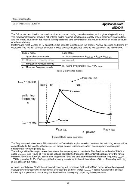
The QR mode, described in the previous chapter, is used during normal operation, which gives a high efficiency.<br />
The maximum frequency mode is not entered during nominal conditions (probably only at maximum input voltage<br />
and low loads). But also in this mode it is still possible to take advantage of the reduced switch-on losses because<br />
of valley switching.<br />
If referring to most Monitor or TV application it is possible to distinguish two stages: Normal operation and Stand-by<br />
operation. The relation between converter modes and load stages has to be as represented in the table below.<br />
Supply mode Load stage<br />
1. <strong>Quasi</strong>-<strong>Resonant</strong> mode A. Normal operation: POUT_MIN < POUT < POUT_MAX<br />
2. Maximum Frequency mode not entered<br />
3. Frequency Reduction mode<br />
4. Minimum Frequency mode<br />
B. Stand-by operation: POUT = PSTAND-BY<br />
Table 2 Converter modes<br />
foscH = 175 kHz<br />
kH MinF RF QR<br />
switching<br />
frequency<br />
foscL = 6 kHz<br />
VVCO,max<br />
12<br />
VVCO,start<br />
frequency limit<br />
POUT_MIN POUT_MAX<br />
Figure 6 Multi mode operation<br />
power<br />
The frequency reduction mode FR (also called VCO mode) is implemented to decrease the switching losses at low<br />
output loads. In this way the efficiency at low output powers is increased, which enables power consumption<br />
smaller than 3W during stand-by.<br />
The voltage at the Sense pin determines where the frequency reduction starts. This fixed sense level of 75mV is<br />
called VVCO,start (see Figure 6). This sense voltage controls the frequency of the internal oscillator over the range<br />
between 75mV and 50mV (At sense level larger than 75mV the oscillator will run on maximum frequency foscH =<br />
175kHz typically). At 50mV (VVCO,max) the frequency is reduced to the minimum level of 6kHz. The valley switching<br />
is still active in this mode.<br />
At sense levels below 50mV the minimum frequency will remain on 6kHz called MinF mode. When the required<br />
output power decreases the <strong>controller</strong> will decrease the on-time, limited TON_MIN = 350ns. As a result of this low<br />
frequency it is possible to run at very low loads <strong>with</strong>out having any output regulation problems.