75W SMPS with TEA1507 Quasi- Resonant Flyback controller - NXP ...
75W SMPS with TEA1507 Quasi- Resonant Flyback controller - NXP ...
75W SMPS with TEA1507 Quasi- Resonant Flyback controller - NXP ...

Create successful ePaper yourself
Turn your PDF publications into a flip-book with our unique Google optimized e-Paper software.
Philips Semiconductors<br />
Application Note<br />
AN00047<br />
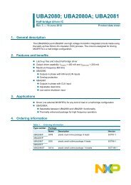
5.1.2 Efficiency<br />
The figure below shows the efficiency measured at two different input voltages respectively 110Vac and 230Vac.<br />
Both curves showing efficiency above 90% at a nominal output power of <strong>75W</strong>. The efficiency stays even above<br />
87% over the power range from 20W to 85W. Efficiency is a big advantage of the <strong>Quasi</strong>-<strong>Resonant</strong> <strong>Flyback</strong><br />
converter compared to the Fixed Frequency <strong>Flyback</strong> converter.<br />
eff[%]<br />
95.0<br />
90.0<br />
85.0<br />
80.0<br />
75.0<br />
Efficiency vs output power<br />
70.0<br />
0.0 20.0 40.0 60.0 80.0 100.0<br />
Pout[W]<br />
Figure 16 Measured efficiency<br />
Note: Only the 185V output is loaded during this measurement<br />
32<br />
Vin = 110Vac<br />
Vin = 230Vac<br />
This high efficiency is mainly achieved because of the ZVS/LVS switching, which reduces the switch-on losses and<br />
makes it possible to use a non-dissipative dV/dt limiter (only a capacitor across the drain-source of the MOSFET).<br />
5.1.3 Over Voltage Protection<br />
To illustrate the accuracy of the Over Voltage Protection a measurement is done at different input voltage and at<br />
different output loads such that the ringing of the reflected output voltage will be different in each condition. As<br />
previous described the ringing of the reflected output voltage is integrated, which makes the Over Voltage<br />
Protection rather accurate. The diagram below shows the OVP level under different conditions.<br />
OVP level[V]<br />
215<br />
210<br />
205<br />
200<br />
195<br />
Over Voltage Protection level<br />
190<br />
0 50 100 150<br />
Iout[mA]<br />
200 250 300<br />
Figure 17 Measured OVP level<br />
110Vac<br />
230Vac<br />
From this measurement it can be seen that the OVP level stays <strong>with</strong>in 5% of the nominal value.