diris a10 - Socomec
diris a10 - Socomec
diris a10 - Socomec

You also want an ePaper? Increase the reach of your titles
YUMPU automatically turns print PDFs into web optimized ePapers that Google loves.
NEW<br />
<strong>diris</strong>_791_b_1_cat<br />
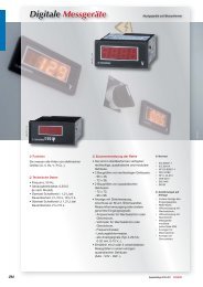
DIRIS A10 Multifunction meters<br />
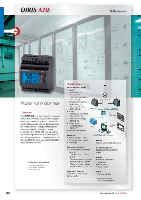
Modular multi function meter<br />
‹ Function<br />
The DIRIS A10 is a multi function meter for<br />
measuring electrical values in low voltage<br />
networks in modular format. It allows all<br />
electrical parameters to be displayed and<br />
the measurement, energy metering and<br />
communication functions to be used.<br />
In addition, the DIRIS A10 has a function<br />
for correcting errors in CT connections. It<br />
also allows variations in temperature to be<br />
detected thanks to its internal temperature<br />
measurement function.<br />
‹ Conformity to standards<br />
• IEC 62053-22 class 0.5S<br />
• IEC 62053-23 class 2<br />
• IEC 61557-12<br />
‹ Applications<br />
Multi-function meter<br />
• Current<br />
- instantaneous:<br />
I1, I2, I3, In<br />
- maximum average:<br />
I1, I2, I3, In<br />
• Voltages & frequency<br />
- instantaneous:<br />
U1, U2, U3, U12,<br />
U23, U31, F<br />
• Power<br />
- instantaneous: 3P, ΣP,<br />
3Q, ΣQ, 3S, ΣS<br />
- maximum average:<br />
ΣP, ΣQ, ΣS<br />
• Power factor<br />
- instantaneous:<br />
3PF, ΣPF<br />
• Internal temperature<br />
Metering<br />
• Active energy: + kWh<br />
• Reactive energy: + kvarh<br />
• Hours:<br />
Harmonic analysis<br />
• Total harmonic distortion<br />
(level 51)<br />
- Currents: thd I1, thd I2,<br />
thd I3<br />
- Phase-to-neutral voltage:<br />
thd U1, thd U2, thd U3<br />
- Phase to phase voltage:<br />
thd U12, thd U23, thd U31<br />
Dual tariff function<br />
Selection of one out of 2<br />
billing tariffs<br />
DIRIS A10 RS485 DIRIS A10<br />
Events<br />
Alarms on all electrical values<br />
Communications (1)<br />
RS485 (JBUS/MODBUS)<br />
digital<br />
Output<br />
• Remote comand of<br />
apparatus<br />
• Alarm report<br />
• Pulse report<br />
Input<br />
• Remote control<br />
(1) Available as an option<br />
(see the following pages).<br />
366 General Catalogue 2011-2012 SOCOMEC<br />
PLC<br />
485<br />
232<br />
PC<br />
CONTROL VISION software<br />
Main<br />
meter panel<br />
Currents<br />
per phase<br />
curve<br />
<strong>diris</strong>_808_c_1_gb_cat<br />
site_321_a
<strong>diris</strong>_791x_b_1_cat<br />
‹ Front panel<br />
<strong>diris</strong>_809_a_1_x_cat<br />
1<br />
‹ Case<br />
90<br />
72<br />
DIRIS A 10<br />
I<br />
P PF<br />
E<br />
C=0,1Wh/imp<br />
‹<br />
Electrical characteristics<br />
V F<br />
°C<br />
TEST<br />
OK<br />
PROG<br />
2<br />
3<br />
4<br />
5<br />
6<br />
7<br />
64<br />
44<br />
Current measurement on high-impedance inputs (TRMS)<br />
Via CT primary 9 999 A<br />
Via CT secondary 5 A<br />
Measurement range 0 … 11 kA<br />
Input consumption 0.6 VA<br />
Measurement updating period 1 s<br />
Accuracy 0.2 %<br />
Sustained overload 6 A<br />
intermittent overload 10 In for 1 s<br />
Voltage measurements (TRMS)<br />
Direct measurement between phases 50 … 500 VAC<br />
Direct measurement between phase and neutral 28 … 289 VAC<br />
Input consumption ≤ 0.1 VA<br />
Measurement updating period 1 s<br />
Accuracy 0.2 %<br />
Sustained overload 800 VAC<br />
Power measurement<br />
Measurement updating period 1 s<br />
Accuracy 0.5 %<br />
Power factor measurement<br />
Measurement updating period 1 s<br />
Accuracy 0.5 %<br />
Frequency measurement<br />
Measurement range 45 … 65 Hz<br />
Measurement updating period 1 s<br />
Accuracy 0.1 %<br />
1. Backlit LCD screen.<br />
2. Direct access key for currents (instant and maximum) and current THD.<br />
3. Direct access key for voltages, frequency and voltage THD.<br />
4. Direct access key for active, reactive and apparent power (instantaneous and max. values) and power<br />
factor.<br />
5. Direct access key for energies and hour meter.<br />
6. Pushbutton for currents, temperatures and CT setup wiring correction.<br />
7. Metrological LED.<br />
45<br />
Type Modular<br />
Number of optional modules 4<br />
Dimensions W x H x D 72 x 90 x 64 mm<br />
Case protection index 30<br />
Front protection rating 52<br />
Display type LCD<br />
Voltage and other connection section 4 mm 2<br />
Connection cross-section of others 2.5 mm 2<br />
Weight 205 g (4825 0010) - 215 g (4825 0011)<br />
Energy accuracy<br />
Active (according to IEC 62053-22) class 0.5 S<br />
Reactive (according to IEC 62053-23) class 2<br />
Auxiliary power supply<br />
Alternating voltage 220 … 277 VAC<br />
AC tolerance ± 15 %<br />
Frequency 50 / 60 Hz<br />
Consumption < 3 VA<br />
Digital output (pulses or on/off)<br />
Number 1<br />
Type 20 / 30 VDC - 0.5 A - 10 VA<br />
Max. number of operations ≤ 10 8<br />
Communication<br />
Link RS485<br />
Type 2 … 3 half duplex wires<br />
Protocol JBUS/MODBUS ® in RTU mode<br />
JBUS/MODBUS ® speed 1400 … 38400 bauds<br />
Operating conditions<br />
Operating temperature - 10 … + 55 °C<br />
Storage temperature - 20 … + 70 °C<br />
Relative humidity 85 %<br />
Multifunction meters<br />
DIRIS A10<br />
SOCOMEC General Catalogue 2011-2012<br />
367
‹ DIRIS A10 - Connection<br />
Low voltage balanced network<br />
Recommandation:<br />
- For IT earthing systems, it is recommended that the CT secondary is not connected to earth.<br />
- When disconnecting the DIRIS, the secondaries of each current transformer must be short-circuited. This operation can be carried out automatically from a product in the SOCOMEC<br />
catalogue, PTI: consult us.<br />
- It is recommended that the earthing point for the DIRIS A10 and the current transformer secondaries should not earthed at the same time.<br />
1 = Fus. 0.5 A gG / 0.5 A class CC<br />
1 1 1<br />
V1 V2 V3 VN<br />
<strong>diris</strong>_810_a_1_gb_cat 3/4 wires with 1 CT<br />
P1<br />
S1<br />
Low voltage unbalanced network<br />
1 = Fus. 0.5 A gG / 0.5 A class CC<br />
1 1 1<br />
V1 V2 V3 VN<br />
<strong>diris</strong>_813_a_1_gb_cat 3/4 wires with 3 CTs<br />
Additional information<br />
0V - +<br />
RS485<br />
I1<br />
S2<br />
S1 S2 S1 S2 S1 S2<br />
P1<br />
S1<br />
<strong>diris</strong>_820_a_1_x_cat Communication via RS485 link<br />
S2<br />
I2<br />
P1<br />
S1<br />
I3<br />
S1 S2 S1 S2 S1 S2<br />
I1<br />
I2<br />
LIYCY-CY<br />
I3<br />
S2<br />
N<br />
L1<br />
L2<br />
L3<br />
N<br />
L1<br />
L2<br />
L3<br />
<strong>diris</strong>_811_a_1_gb_cat<br />
<strong>diris</strong>_814_a_1_gb_cat<br />
Single phase<br />
1 = Fus. 0.5 A gG / 0.5 A class CC<br />
1<br />
V1 V2 V3 VN<br />
3 wires with 2 CTs<br />
1 = Fus. 0.5 A gG / 0.5 A class CC<br />
1 1 1<br />
V1 V2 V3 VN<br />
368<br />
General Catalogue 2011-2012 SOCOMEC<br />
P1<br />
S1<br />
I1<br />
S2<br />
S1 S2 S1 S2 S1 S2<br />
P1<br />
S1<br />
<strong>diris</strong>_821_a_1_x_cat<br />
S2<br />
I2<br />
P1<br />
S1<br />
I3<br />
S1 S2 S1 S2 S1 S2<br />
Use of 2 CTs reduces by 0.5% the accuracy of<br />
the phase, whose current is worked out by vector<br />
calculation.<br />
I1<br />
I2<br />
L1<br />
N<br />
L1<br />
L2<br />
L3<br />
S2<br />
1 = Fus. 0.5 A gG / 0.5 A class CC<br />
1 1<br />
AC & DC auxiliary power supply<br />
I3<br />
<strong>diris</strong>_815_a_1_gb_cat<br />
V1 V2 V3 VN<br />
<strong>diris</strong>_812_a_1_gb_cat Two phase<br />
3 wires with 2 CTs<br />
1 = Fus. 0.5 A gG / 0.5 A class CC<br />
220/ 277 VAC (IEC)<br />
20 22<br />
AUX<br />
1 1 1<br />
V1 V2 V3 VN<br />
P1<br />
S1<br />
I1<br />
S2<br />
S1 S2 S1 S2 S1 S2<br />
It is recommended that the auxiliary power supply be protected by the use of 500 mA<br />
gG fuses.<br />
P1<br />
S1<br />
I1<br />
P1<br />
S1<br />
I2<br />
I2<br />
S2<br />
I3<br />
S1 S2 S1 S2 S1 S2<br />
Use of 2 CTs reduces by 0.5% the accuracy of<br />
the phase, whose current is worked out by vector<br />
calculation.<br />
I3<br />
L1<br />
L2<br />
L1<br />
L2<br />
L3
<strong>diris</strong>_816_a_1_x_cat<br />
<strong>diris</strong>_816_a_1_x_cat<br />
‹ Terminals<br />
12 14 16 2 20 22 1 3 5 7 9 11<br />
V1 V2 V3 VN A U X S1 S2 S1 S2 S1 S2<br />
DIRIS A10<br />
S1 - S2: current inputs.<br />
AUX: auxiliary power supply Us.<br />
V1, V2, V3 & VN: voltage inputs.<br />
Communication (option)<br />
DIRIS A10<br />
RS485 link.<br />
13 15 17<br />
0V + -<br />
RS485<br />
‹ References<br />
<strong>diris</strong>_819_b_1_x_cat<br />
Output<br />
DIRIS A10<br />
4 - 6: output n°1<br />
4 6<br />
OUT 1<br />
I1<br />
Basic device DIRIS A10<br />
Description Reference<br />
DIRIS A10 (grey colour available on request) 4825 0010<br />
DIRIS A10 with JBUS/MODBUS communication via RS485 (grey colour available on request) 4825 0011<br />
I2<br />
I3<br />
Multifunction meters<br />
DIRIS A10<br />
SOCOMEC General Catalogue 2011-2012<br />
369<br />
18<br />
DIRIS A10<br />
8 - 10: input n°1<br />
Description of accessories To be ordered by multiple Reference<br />
Fuse combination switches for the protection of voltage inputs (type RM) 3 poles 4 5601 0018<br />
Fuse combination switches for the protection of the auxiliary supply (type RM) 1 pole + neutral 6 5601 0017<br />
Fuses type gG 10x38 0.5 A 10 6012 0000<br />
Current transformers range See page 334<br />
Services and Technical assistance<br />
Our expertise extends to a complete offer of<br />
services like commissioning installation audit,<br />
training, maintenance and project engineering.<br />
<strong>diris</strong>_818_a_1_x_cat<br />
Input<br />
8 10<br />
IN 1<br />
<strong>diris</strong>_791_b_1_cat