MainStay™ Disposable Articulator Instructions - Whip Mix
MainStay™ Disposable Articulator Instructions - Whip Mix
MainStay™ Disposable Articulator Instructions - Whip Mix

You also want an ePaper? Increase the reach of your titles
YUMPU automatically turns print PDFs into web optimized ePapers that Google loves.
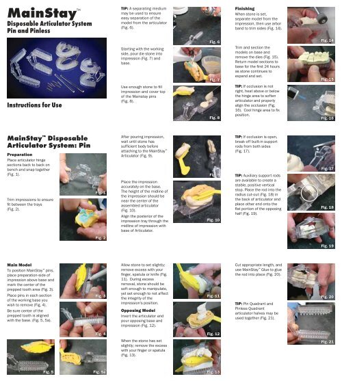
MainStay <br />
<strong>Disposable</strong> <strong>Articulator</strong> System<br />
Pin and Pinless<br />
<strong>Instructions</strong> for Use<br />
MainStay <strong>Disposable</strong><br />
<strong>Articulator</strong> System: Pin<br />
Preparation<br />
Place articulator hinge<br />
sections back to back on<br />
bench and snap together<br />
(Fig. 1).<br />
Trim impressions to ensure<br />
fit between the trays<br />
(Fig. 2).<br />
Main Model<br />
To position MainStay pins,<br />
place preparation-side of<br />
impression above base and<br />
mark the center of the<br />
prepped tooth area (Fig. 3).<br />
Place pins in each section<br />
of the working base you<br />
wish to remove (Fig. 4).<br />
Be sure center of the<br />
prepped tooth is aligned<br />
with the base. (Fig. 5, 5a).<br />
Fig. 1<br />
Fig. 2<br />
Fig. 3<br />
Fig. 4<br />
Fig. 5 Fig. 5a<br />
TIP: A separating medium<br />
may be used to ensure<br />
easy separation of the<br />
model from the articulator<br />
(Fig. 6).<br />
Starting with the working<br />
side, pour die stone into<br />
impression (Fig. 7) and<br />
base.<br />
Use enough stone to fill<br />
impression and cover top<br />
of the Mainstay pins<br />
(Fig. 8).<br />
After pouring impression,<br />
wait until stone has<br />
sufficient body before<br />
attaching to the MainStay <br />
<strong>Articulator</strong> (Fig. 9).<br />
Place the impression<br />
accurately on the base.<br />
The height of the midline of<br />
the impression should be<br />
near the center of the<br />
assembled articulator<br />
(Fig. 10).<br />
Align the posterior of the<br />
impression tray through the<br />
midline of impression with<br />
base of <strong>Articulator</strong>.<br />
Allow stone to set slightly;<br />
remove excess with your<br />
finger, spatula or knife (Fig.<br />
11). During excess<br />
removal, stone should be<br />
soft enough to manipulate,<br />
yet set enough to not affect<br />
the integrity of the<br />
impression’s position.<br />
Opposing Model<br />
Invert the articulator and<br />
pour opposing base and<br />
impression (Fig. 12).<br />
When the stone has set<br />
slightly; remove the excess<br />
with your finger or spatula<br />
(Fig. 13).<br />
Fig. 6<br />
Fig. 7<br />
Fig. 8<br />
Fig. 9<br />
Fig. 10<br />
Fig. 11<br />
Fig. 12<br />
Fig. 13<br />
Finishing<br />
When stone is set,<br />
separate model from the<br />
impression, then use arbor<br />
band to trim sides (Fig. 14).<br />
Trim and section the<br />
models on base and<br />
remove the dies (Fig. 15).<br />
Return model sections to<br />
base for the first 24 hours<br />
as stone continues to<br />
expand and set.<br />
TIP: If occlusion is not<br />
right, heat above or below<br />
the hinge area to soften<br />
articulator and properly<br />
align the occlusion (Fig.<br />
16). Cool hinge area to fix<br />
position.<br />
TIP: If occlusion is open,<br />
break off built-in support<br />
rods from both sides<br />
(Fig. 17).<br />
TIP: Auxiliary support rods<br />
are available to create a<br />
stable, positive vertical<br />
stop. Place the rod into the<br />
radius cut-out (Fig. 18) in<br />
the back of articulator and<br />
place other end onto the<br />
flat portion of the opposing<br />
half (Fig. 19).<br />
Cut appropriate length, and<br />
use MainStay Glue to glue<br />
the rod into place (Fig. 20).<br />
TIP: Pin Quadrant and<br />
Pinless Quadrant<br />
articulator halves may be<br />
used together (Fig. 21).<br />
Fig. 14<br />
Fig. 15<br />
Fig. 16<br />
Fig. 17<br />
Fig. 18<br />
Fig. 19<br />
Fig. 20<br />
Fig. 21
MainStay <strong>Disposable</strong><br />
<strong>Articulator</strong> System: Pinless<br />
Preparation<br />
Place articulator hinge<br />
sections back to back on<br />
bench and snap together<br />
(Fig. 1).<br />
Be sure center of the<br />
prepped tooth is aligned<br />
with the base. The<br />
impression should also be<br />
centered between the two<br />
halves of the articulator<br />
(Fig. 3).<br />
TIP: A separating medium<br />
may be used to ensure<br />
easy separation of the<br />
model from the articulator<br />
(Fig. 4).<br />
Processing<br />
Starting with the working<br />
side, pour die stone into<br />
impression (Fig. 5) and<br />
base.<br />
Wait until stone has<br />
sufficient body before<br />
attaching to the MainStay <br />
<strong>Articulator</strong> (Fig. 6).<br />
Fig. 1<br />
Fig. 2<br />
Fig. 3<br />
Fig. 4<br />
Fig. 5<br />
Fig. 6<br />
Allow the stone to set<br />
slightly; remove excess with<br />
your finger, spatula or knife<br />
(Fig. 7). During excess<br />
removal, stone should be<br />
soft enough to manipulate,<br />
yet set enough to not affect<br />
the integrity of the<br />
impression’s position.<br />
Opposing Model<br />
Invert articulator and pour<br />
opposing base and<br />
impression (Fig. 8).<br />
Align the posterior of the<br />
impression tray through the<br />
midline of the impression<br />
with the base of <strong>Articulator</strong>.<br />
When stone has set<br />
slightly; remove excess with<br />
finger or spatula (Fig. 9).<br />
Finishing<br />
When stone is set,<br />
separate model from the<br />
impression, then use arbor<br />
band to trim sides (Fig. 10).<br />
Section models on base<br />
and remove the dies (Fig.<br />
11) using a rocking motion<br />
if necessary. Return model<br />
sections to the base for the<br />
first 24 hours as stone<br />
continues to expand and<br />
set.<br />
TIP: If occlusion is not<br />
right, heat above or below<br />
the hinge area to soften the<br />
articulator and properly<br />
align the occlusion (Fig.<br />
12). Cool the hinge area to<br />
fix the position.<br />
Fig. 7<br />
Fig. 8<br />
Fig. 9<br />
Fig. 10<br />
Fig. 11<br />
Fig. 12<br />
TIP: If occlusion is open,<br />
break off built-in support<br />
rods from both sides<br />
(Fig. 13).<br />
TIP: Auxiliary support rods<br />
are available to create a<br />
stable, positive vertical<br />
stop. Place the rod into the<br />
radius cut-out (Fig. 14) in<br />
the back of one half of the<br />
articulator and place the<br />
other end onto the flat<br />
portion of the opposing half<br />
(Fig. 15).<br />
Cut appropriate length, and<br />
use MainStay Glue to glue<br />
the rod into place (Fig. 16).<br />
TIP: Pin Quadrant and<br />
Pinless Quadrant<br />
articulator halves may be<br />
used together (Fig. 17).<br />
<strong>Whip</strong> <strong>Mix</strong> Corporation<br />
361 Farmington Avenue<br />
Louisville, KY USA 40209<br />
Toll-Free: 800-626-5651<br />
Phone: 502-637-1451<br />
Fax: 502-634-4512<br />
www.whipmix.com<br />
FN 02DispArt AA 0612<br />
Fig. 13<br />
Fig. 14<br />
Fig. 15<br />
Fig. 16<br />
Fig. 17